Network Fabrics#
Building systems by SU provides the most efficient designs. However, if a different node count is required due to budgetary constraints, data center constraints, or other needs, the fabric should be designed to support the full SU, including leaf switches and leaf-spine cables, and leave the portion of the fabric unused where these nodes would be located. This will ensure optimal traffic routing and ensure that performance is consistent across all portions of the fabric.
DGX SuperPOD configurations utilize four network fabrics:
-Compute Fabric -Storage Fabric -In-Band Management Network -Out-of-Band Management Network
Each network is detailed in this section.
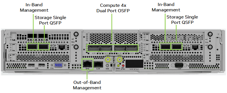
Figure 4 shows the ports on the back of the DGX H100 CPU tray and the connectivity provided. The compute fabric ports in the middle use a two-port transceiver to access all eight GPUs. Each pair of in-band management and storage ports provide parallel pathways into the DGX H100 system for increased performance. The OOB port is used for BMC access. (The LAN port next to the BMC port is not used in DGX SuperPOD configurations.)
Figure 4. DGX H100 network ports
Compute—InfiniBand Fabric#
Figure 5 shows the compute fabric layout for the full 127-node DGX SuperPOD. Each group of 32 nodes is rail-aligned. Traffic per rail of the DGX H100 systems is always one hop away from the other 31 nodes in a SU. Traffic between nodes, or between rails, traverses the spine layer.
Figure 5. Compute InfiniBand fabric for full 127 node DGX SuperPOD
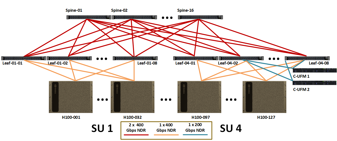
Table 4 shows the number of cables and switches required for the compute fabric for different SU sizes.
SU Count |
Node Count |
GPU Count |
InfiniBand Switch Count |
Cable Counts |
||
|---|---|---|---|---|---|---|
Leaf |
Spine |
Compute and UFM |
Spine-Leaf |
|||
1 |
31¹ |
248 |
8 |
4 |
252 |
256 |
2 |
63 |
504 |
16 |
8 |
508 |
512 |
3 |
95 |
760 |
24 |
16 |
764 |
768 |
4 |
127 |
1016 |
32 |
16 |
1020 |
1024 |
¹. This is a 32 node per SU design, however a DGX system must be removed to accommodate for UFM connectivity. |
||||||
Storage—InfiniBand Fabric#
The storage fabric employs an InfiniBand network fabric that is essential to maximum bandwidth (Figure 6). This is because the I/O per-node for the DGX SuperPOD must exceed 40 GBps. Highbandwidth requirements with advanced fabric management features, such as congestion control and AR, provide significant benefits for the storage fabric.
Figure 6. InfiniBand storage fabric logical design
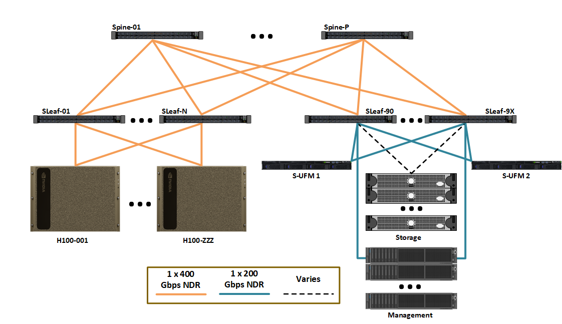
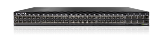
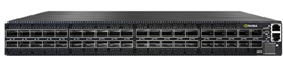
The storage fabric uses MQM9700-NS2F switches (Figure 7). The storage devices are connected at a 1:1 port to uplink ratio. The DGX H100 system connections are slightly oversubscribed with a ratio near 4:3 with adjustments as needed to enable more storage flexibility regarding cost and performance.
Figure 7. MQM9700-NS2F switch
In-Band Management Network#
The in-band management network provides several key functions:
Connects all the services that manage the cluster.
Enables access to the home filesystem and storage pool.
Provides connectivity for the in-cluster services such as Base Command Manager, Slurm and to other services outside of the cluster such as the NGC registry, code repositories, and data sources.
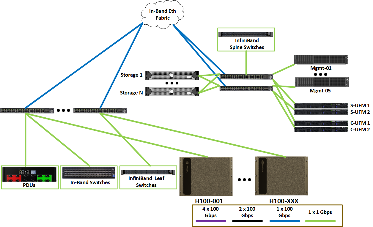
Figure 8 shows the logical layout of the in-band Ethernet network. The in-band network connects the compute nodes and management nodes. In addition, the OOB network is connected to the in-band network to provide high-speed interfaces from the management nodes to support parallel operations to devices connected to the OOB storage fabric, such as storage.
Figure 8. In-band Ethernet network
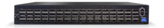
The in-band management network uses SN4600C switches (Figure 9).
Figure 9. SN4600C switch
Out-of-Band Management Network#
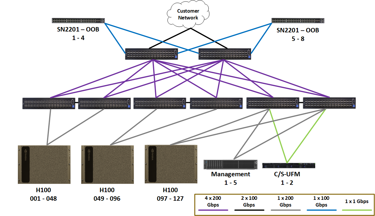
Figure 10 shows the OOB Ethernet fabric. It connects the management ports of all devices including DGX and management servers, storage, networking gear, rack PDUs, and all other devices. These are separate onto their own fabric because there is no use-case where users need access to these ports and are secured using logical network separation.
Figure 10 Logical OOB management network layout
The OOB management network uses SN2201 switches (Figure 11).
Figure 11. SN2201 switch