|
|
DriveWorks SDK Reference| 0.6.67 Release |
|
|
DriveWorks SDK Reference| 0.6.67 Release |
The GUI recording tool provides an interface that provides visual information about what is being recorded.
The distributed recording is in the tools/ folder.
 # cd /usr/local/driveworks/tools
 # ./recorder-qt
The home screen of the recorder GUI is composed of several parts as illustrated in the following screenshot.
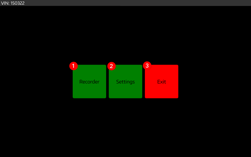
The main screen of the recorder GUI is composed of several parts as illustrated in the following screenshot:
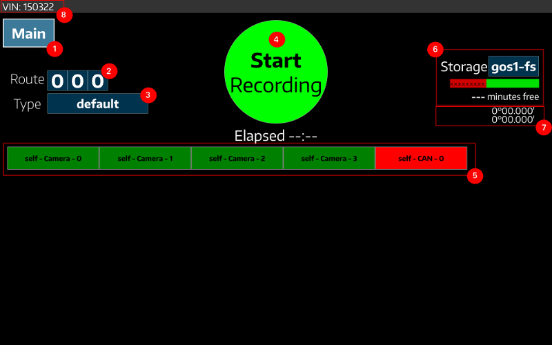
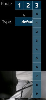
The route can be set by selecting numbers from the 3 drop boxes.
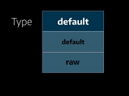
The Configuration switching drop box lists the available configurations and makes the recorder switch to the selected configuration. A two-configuration setup is like below:
When you press the Record button, the application starts recording and the Start button is replaced by a Stop Recording button.
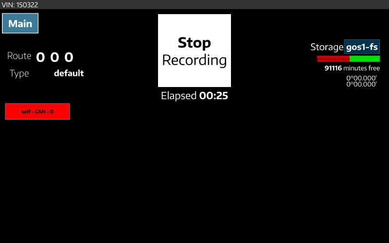
The Elapsed time item marked in the picture indicates the time elapsed since the start of the recording. Pressing the RECORD button again stops the current recording procedure.
The Start/Stop Recording button conveys the following information:
recorder-config.json file specifies a GPS sensor and no GPS fix is available, the Record button is greyed out. It returns to its normal appearance until a GPS fix is available.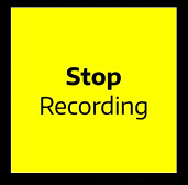
If sensor initialization succeeds, a block for the sensor containing its type and channel # are added to the grid in the recoder window. These blocks are used to indicate sensor status, generally: Good, warning and error. The color of the sensor icons indicate the statuses - green, yellow, and red respectively.
When no data is written to any record file for five seconds or more, recorder-qt displays a warning.
recorder-qt raises and error in the following situations:
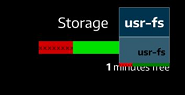
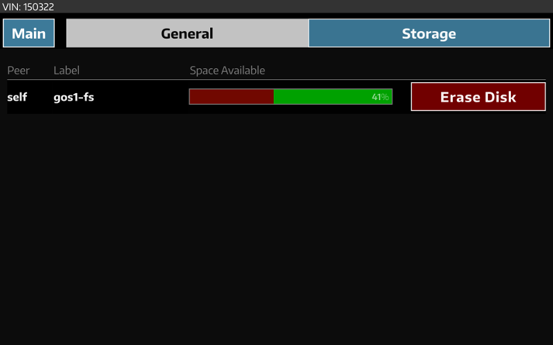
The Storage field shows the storage usage, including the total free percentage, the estimated total remaining recording time, and the usage of each avaiable storage device. Usage of each storage device can be checked by opening the storage drop box as shown in the following illustration.
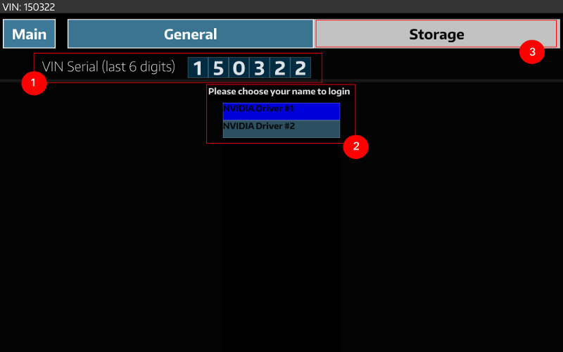
Currently, the settings view provides the following functionality:
A list of driver names can be provided by adding a new entry into recorder-qt-config.json:
"login-file": "<path/to/file/with/driver/names>"
The path specified should contain a file with a driver name on each line.
This screen allows one to erase disk volumes that are connected to the device. In a distributed recording environment, this screen has capability to erase disks on all slave devices, as well.
The DriveWorks recorder is configurable with a JSON file. By default, the JSON file that is read into the recorder is recorder-qt-config.json. This file is auto-generated when you run the tool and the file is not present. A different file can be specified with the --config-file= command-line option:
# ./recorder-qt --config-file=path/to/user/config.json
The JSON file points to other JSON config files that configure the sensors. Each of the sub JSON files configure sensors for recording. Select the sub JSON files from the recorder app.
For information on the JSON config file description, see:
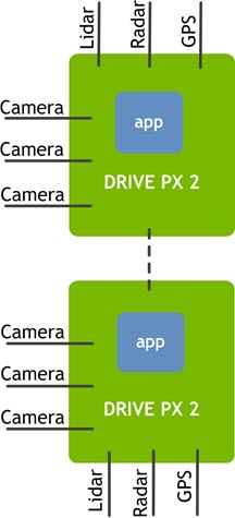
The Distributed Recording application allows multiple DRIVE PX 2 sensors across multiple DRIVE PX 2 devices to log synchronized data. The sample diagram below shows two DRIVE PX 2 platforms with the recording application, each collecting their own data. For each recorder, data is stored with a timestamp that records the time, in milliseconds. Data between the two DRIVE PX 2 platforms are sycnronized based on timestamps. Multiple sensors allow for higher accuracy, and the exact timestamps ensure precise synchronization between the devices.
The GUI tool synchronize with other instances of the tool running in other systems reachable by the network, providing distributed recording capabilities.
This can be achieved by selecting multiple recorder apps to be part of a group via the JSON file. In this group, there is one master and several slaves. The master controls the slaves and displays the recording status for the whole group. Specifically, it displays that recording is on if any members of the group are recording. Recorders communicate with each other through UDP broadcasting or multicasting. When broadcasting, recorders in the same subnet are in the same group; in multicasting mode, recorders in the same IPv4 multicast group can talk to each other. Multicast is the default.
The recorder supports a pre recording script that is scheduled to run before each recording is started. The recording directory is passed as an argument to the pre-recording script.
This script to be executed is specified in the JSON file.
The recorder supports a post-recording script that is scheduled to run after each recording is complete. The recording directory is passed as an argument to the pre-recording script.
This script to be executed is specified in the JSON file.
In order to distribute recording across multiple apps, add record-group in the JSON configuration. In a distributed recording environment, the master sends the recording library configurations to each of the slaves upon connection. If this record-group key is not present, the recorder operates in stand-alone mode.
Below is an example of a master configuration:
"record-group": {
    "name": "default-peer",
    "master": true,
    "peer-info": [
        {
            "name": "TB1",
            "configurations": [
                {"name": "TB1","path":"/home/nvidia/recorder-config-tb1.json"}
            ]
        }
   ]
},
When the master field is missing, a slave is defined. Since no communication mode is specified, multicast is used, and the default multicast group is 239.127.12.15 with port 12621. More detailed settings are available:
"record-group": {
    "name": "default-peer",
    "master": false,
    "multicast": {
        "preferred-ip": "192.168.1.1",
        "group-address": "239.127.12.15"
    }
},
When the host machine has more than one network interface, preferred-ip specifies the one used for communication. group-address customizes the multicast group. Both of these fields are optional.
To configure a peer to broadcast its messages:
"record-group": {",
    "name": "default-peer",
    "master": false,
    "broadcast": {
        "preferred-ip": "192.168.1.1"
    }
},
You can set a VIN code to identify the records. The sample writes the VIN code to a file named vin in each recording directory.
"vin": "123098",
Log level control is illustrated as below. Supported levels are verbose, debug, warning, error, and fatal.
"log-level": "info",
Execute a pre record script as follows:
"pre-record-script":"${APP_DIR}/scripts/bash/default-pre-record-script",
Execute a post record script as follows:
"post-record-script":"${APP_DIR}/scripts/bash/default-post-record-script",
This is the default script on NVIDIAreg; DRIVEtrade; 5.0 Linux. It copies dmesg output and syslog to the logs folder of the recording directory.
In order to set sub JSON configuration files, a configurations key must be added to the JSON file:
"configurations": [
    {"name":"raw", "path":"${CONFIG_FILE_DIR}/raw-config.json"},
    {"name":"h264", "path":"${CONFIG_FILE_DIR}/h264-config.json"}
]
The names of items in configurations appear in the recorder's UI as a dropdown box.