Stereo Calibration Sample
Table of Contents
- Note
- SW Release Applicability: This sample is available in both NVIDIA DriveWorks and NVIDIA DRIVE Software releases.
Description
The Stereo Calibration sample demonstrates how to estimate the relative extrinsics of the right camera with respect to a left camera in a typical stereo setup with the NVIDIA® DriveWorks Calibration Engine.
Running the Sample
The Stereo Calibration sample, sample_calibration_stereo, accepts the following optional parameters. If none are specified, the relative right camera extrinsics are estimated on a default dataset.
./sample_calibration_stereo --path=[path/to/data/folder]
                            --rig=[path/to/rig/configuration/file]
                            --camera-sensor-left=[integer or string]
                            --camera-sensor-right=[integer or string]
                            --matches-max-count=[integer]
where
--path=[path/to/data]
    The base path to the recorded data.
    Default value: path/to/data/data/samples/stereo/

--rig=[path/to/rig/configuration/file]
    Path to the rig configuration file.
    Default value: path/to/data/samples/stereo/stereo_offset.json

--camera-sensor-left=[integer or string]
    The index or the name of the left camera in the rig configuration file
    Default value: left

--camera-sensor-right=[integer or string]
    The index or the name of the right camera in the rig configuration file
    Default value: right

--matches-max-count=[integer]
    Maximum number of matches. A higher number can increase the calibration accuracy.
    Default value: 8000

--profiling=[0|1]
    When set to 1, enables sample profiling.
    Otherwise, profiling is disabled.
    Default value: 1
Output
The sample does the following:
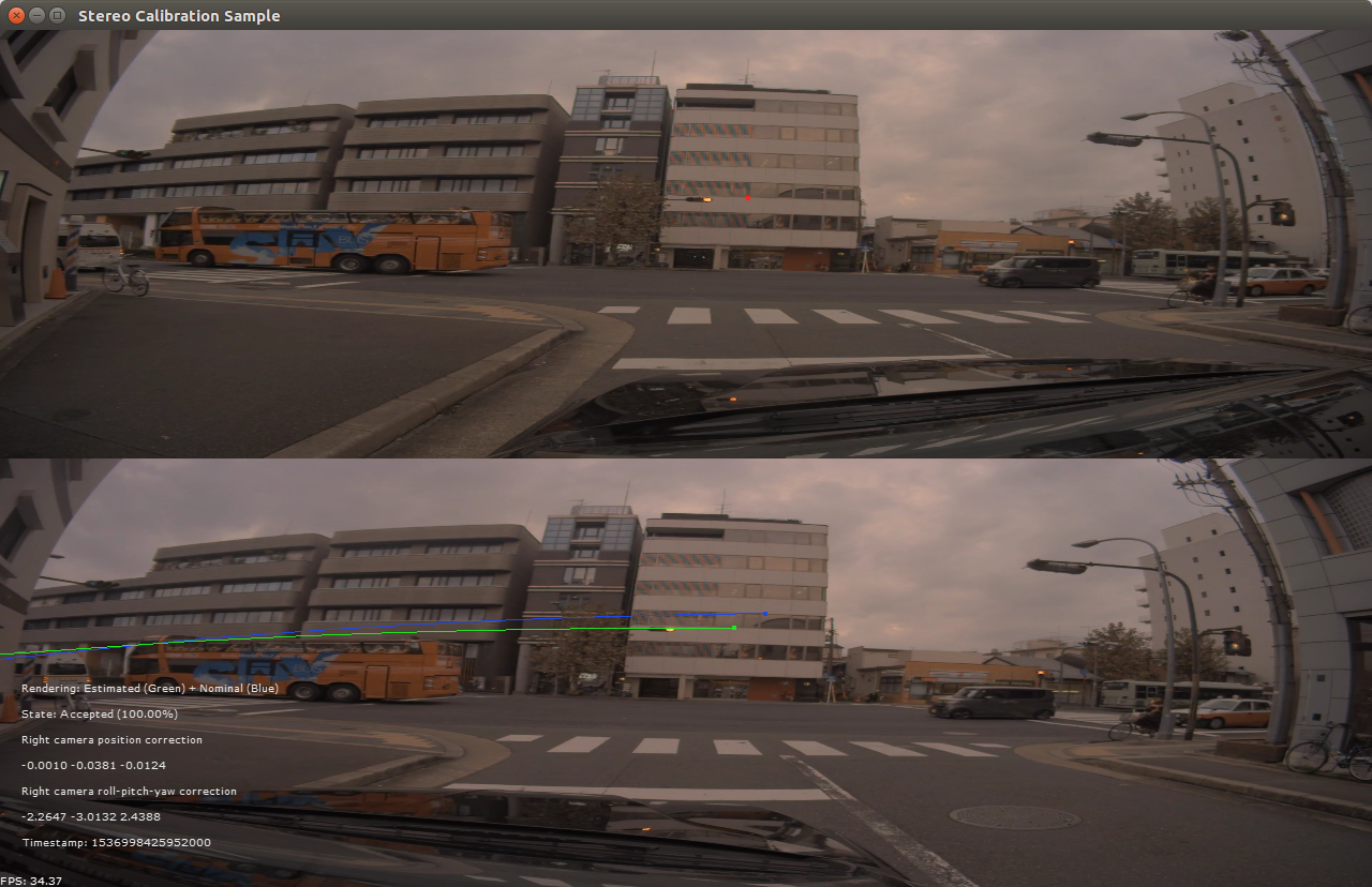
- Creates a window.
- The window has two tiles. In the top tile the left video is shown, in the bottom tile the right video is shown.
- Displays a red point in the top tile (left image). The position of this point can be changed by left clicking on the top image. The point can be removed by right clicking.
- Displays nominal calibration indicators (blue) and, after convergence, a corrected calibration indicator (green) in the bottom tile. The indicators show the nominal/estimated epipolar line, respectively. The marked endpoint of each epipolar line represents the point at infinity. The epipolar line should pass through the point corresponding to the red point marked in the left camera frame.
After convergence, the sample runs the sample data in a loop, during which calibration is further refined.
Stereo Calibration
Additional information
For more information on Stereo calibration, see Epipolar-based Stereo Self-Calibration.