Table of Contents
- Local Space Lane Divider Line Segments
- Local Cartesian Coordinate System
- Filtering
- Local Space Feature Line Segments
- Compute Bounds
- Compute Bearing
- Compute Local To ENU
- Transform Polylines
- Transform Point
- Interpolation Between Polylines
- Neighbor Lanes
- Stitching of Lane Geometry
- Distance Calculations
- Note
- SW Release Applicability: This tutorial is applicable to modules in NVIDIA DRIVE Software releases.
Local Space Lane Divider Line Segments
This helper function combines a few things to transform and filter the lane divider geometry. It does the following:
- Transforms from WGS84 coordinates into in a user-defined local Cartesian coordinate space.
- Transforms the polylines into a list of line segments.
- Filters the line segments by a bounding box defined in local space.
- Filters the line segments by direction.
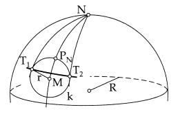
Local Cartesian Coordinate System
The local coordinate system is defined by:
- Point in WGS84 coordinates
- Rotation matrix
The point defines the origin of the east-north-up (ENU) coordinate system on the tangent plane of the Earth spheroid. The basis vectors of the ENU space are:
(1,0,0) = east
(0,1,0) = north
(0,0,1) = up
The rotation matrix transforms from the local coordinate system into the ENU space. It defines the user local space of the returned coordinates. The basis vectors of the user local space can be interpreted as:
(1,0,0) = forward
(0,1,0) = left
(0,0,1) = up
This means that if the rotation matrix is an identity matrix, the local space is facing east.
There is also a helper function dwMaps_computeRotationFromBearing() that creates the rotation matrix from a single bearing value.
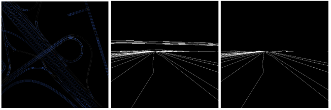
Filtering
The direction filtering allows to discard all line segments that do not point into a desired direction. For example, providing a direction filter vector of (1,0,0) with an angle of 0.25*Pi will only return line segments that have an angle of less than 45 degrees compared to the viewing direction. This can be used to filter out bridges that cross the current Road Segment horizontally, as shown in the following images:
Local Space Feature Line Segments
This function has the same functionality as dwMaps_transformLaneDividersToLocalLines(), but for features instead of lane dividers.
Compute Bounds
The query functions require a bounding box in WGS84 coordinates to define the area of interest. The size of the longitude/latitude box for a given radius in meters varies with latitude, so it is not obvious how big the WGS84 bounding box must be to cover a desired radius in meters. The dwMaps_computeBounds() function does this calculation. It returns the bounds that fully contain a given circle on the earth surface.
Compute Bearing
There is a helper function to compute the bearing (clock-wise angle from north) from a current and a target position:
Compute Local To ENU
The coordinate space in the functions that transform into local space is defined by a position and a rotation matrix that transforms from local coordinate space into the ENU coordinate system. dwMaps_computeRotationFromBearing() is a helper function that creates the rotation matrix from a bearing angle. It is a clockwise rotation around the z-axis by bearing angle. The a helper for the opposite calculation is also available: dwMaps_computeBearingFromRotation(). It projects the forward direction onto the x-y-plane of the ENU space, and expresses the direction as a bearing angle (clockwise relative to north).
Transform Polylines
All map data polylines are defined in WGS84 coordinates by longitude angle, latitude angle and height above the earth spheroid surface. dwMaps_transformPolylines() transforms an array of WGS84 coordinate polylines into a Cartesian local space, the same way it is done for the getLaneDividerLinesLocal query, however it just returns the polylines in local space (as opposed to returning filtered line segments).
Transform Point
The dwMaps_transformPoint function does the same as dwMaps_transformPolylines, but for a single point only.
Interpolation Between Polylines
Interpolation between two Polylines
This helper function provides interpolation between 2 polylines. It can be used to create a path that connects two parallel polylines, for example to model a lane change.
Input are:
- the source polyline
- the target polyline
- the start of the interpolation (distance in meters from first source polyline point)
- the end of the interpolation (distance in meters from the first target polyline point)
- the step size to define where interpolation points are evaluated
- a function callback to define the interpolation curve (linear by default)
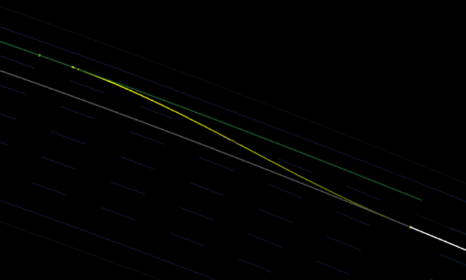
In the above example image, the interpolation function is:
1.0 - 0.5*(cos(d * Pi) + 1.0);
It maps the input parameter d, which goes from 0.0 to 1.0 and represents the distance from interpolation start to interpolation target (horizontal distance in the example image), to the target range 0.0 to 1.0 that represents the weight between source and target polyline.
Neighbor Lanes
Given a dwMapsLane, it is possible to figure out how many lanes are left and right on the current road segment. To query the number of lanes on a side, call:
There are two return values, the total number of lanes on that side, and the number accessible ones. Accessible lanes are the ones that can be reached from the current lanes through a lane change, i.e. all lane dividers in between can be legally crossed.
The side can be requested either relative to the polyline directions on the road segment, or relative to the driving direction on the input lane (these directions are not necessarily the same).
A neighbor lane can be access by calling:
offset = 1 returns the directly adjacent lane, offset = 2 the next one, etc.
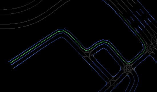
Stitching of Lane Geometry
Given a list of connected dwMapsLane objects, this helper functions stitches the requested geometry (lane center line, left lane divider, right lane divider) into one connected polyline:Distance CalculationsDistance Calculations
Distance Calculations
The length of a polyline of WGS84 points can be computed with the helper function
There is also a helper function that computes the Euclidean distance between two WGS84 points:
For more information see Map Access Sample .