1 # Copyright (c) 2018-2020 NVIDIA CORPORATION. All rights reserved.
3 @page dwx_recording_devguide_basic_recording Basic Recording
6 @note SW Release Applicability: This tutorial is applicable to modules in both **NVIDIA DriveWorks** and **NVIDIA DRIVE Software** releases.
8 This section provides guidance on recording a limited number of sensors on
9 a single NVIDIA<sup>®</sup> Xavier<sup>®</sup> processor.
11 @section dwx_recording_devguide_basic_basic_steps Basic Steps
13 The following are the steps to log data in the device.
14 - @ref dwx_recording_devguide_basic_verify
15 - @ref dwx_recording_devguide_basic_configure_to_acquire
16 - @ref dwx_recording_devguide_basic_start_app
18 <a name="prerequisites">
21 Before you can use the NVIDIA<sup>®</sup> DriveWorks recording tools or DriveWorks sample sensor
22 applications, you must ensure that:
23 - NVIDIA DRIVE platform is flashed with an operating system.
24 - DriveWorks SDK is installed on the device. For more information, see
25 @ref dwx_devguide_getting_started.
26 - Only supported sensors are used.
27 - An ext4-formmated eSATA/USB3.0 SSD is mounted on the target
29 @subsection dwx_recording_devguide_basic_verify Step 1: Verify the Sensors Are Collecting Data
31 In this step, you will connect the sensor to the device and then verify that the
32 sensor is collecting data.
34 @warning Turn off the device before connecting or disconnecting a sensor.
36 You can determine whether the sensor is correctly connected and collecting data by starting the appropriate sample application.
37 The following table lists some of the samples.
39 | Sensor | Sample Application|
40 |--------|-------------------|
41 | Camera | sample_camera_gmsl_custom |
42 | GPS | sample_gps_logger |
43 | Lidar | sample_lidar_replay |
44 | Radar | sample_radar_replay |
45 | IMU | sample_imu_logger |
46 | CAN | sample_canbus_logger |
48 For a complete list of samples, see @ref dwx_samples_section.
50 @subsection dwx_recording_devguide_basic_configure_to_acquire Step 2: Configure the Device to Acquire Data
52 After verifying that the sensors are functional, you can create a DriveWorks Rig Configuration file
53 to specify sensors for recording. For more information on creating a rig file for recording,
54 see the recording @ref dwx_config_ref or the [Examples](#examples) section in this chapter.
56 @subsection dwx_recording_devguide_basic_start_app Step 3: Start the Recording Application and Acquire the Data
58 After you modify the configuration file to collect and store the data, you can
59 begin logging the data from the sensors. You can use the basic, TextUI, or GUI
61 - tools/capture/recorder
62 - tools/capture/recorder-tui
63 - tools/capture/recorder-qtgui
65 All tools collect the data from the sensors, synchronize the data by adding
66 time stamps, and save the data to the storage device.
68 @subsubsection dwx_recording_devguide_basic_can Recording SocketCAN Data
70 If you are using the @ref dwx_recorder_tool, and recording data from SocketCAN on Linux,
71 you must start the recording tool with root privileges. For example:
73 # sudo tools/capture/recorder
75 The sensor driver uses an IOCTL command to enable HW timestamping for the
78 The sudo preface is not required for the @ref dwx_recorder_textui_tool or the @ref dwx_gui_recording2_tool,
79 as it is handled internally.
81 @section dwx_recording_devguide_basic_examples Examples
83 This section shows how to log data from the connected sensors. The applications
84 can check that the sensors can collect data and saves the data to the Xavier
87 @subsection dwx_recording_devguide_basic_camera_sensor_data_acquisition Cameras
89 This section explains how to use the DriveWorks recorder to acquire data from
92 @subsubsection dwx_recording_devguide_basic_single_cam Recording from a Single Camera
94 This procedure shows how to record data from a single (AR0231) camera.
96 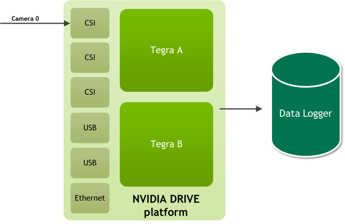
98 #### To record data from a single camera
100 1. With the device powered off, connect the camera to port A0 of a camera group.
101 @warning Turn off the device before connecting or disconnecting a sensor.
102 2. Turn on the device and open a terminal window.
103 3. On the target, navigate to:
105 /usr/local/driveworks/bin/
106 4. Run the following command to verify that your camera is correctly connected to the device:
108 If the camera type is c-ov10649-b1 and the CSI port is the default ab, execute:
113 ./sample_camera_gmsl --camera-type=<camera_type>
114 Where <camera_type> is the camera.
116 For example, if your camera is an AR0231-RCCB sensor with a SF3324 module and you want to run in BAE exposure mode, run the following command:
118 ./sample_camera_gmsl --camera-type=ar0231-rccb-bae-sf3324
119 A window appears with video if the camera is correctly connected to the
120 device and the drivers are running.
122 Close the window to stop the camera application.
124 5. On the target, navigate to:
126 /usr/local/driveworks/tools/capture/
128 6. Copy the default configuration file in `configs/hyperion7_1/release.json`, and include the following
129 sensor block for camera. All the other sensor blocks can be removed.
132 "name": "camera:front:center:120fov",
133 "nominalSensor2Rig": {
146 "parameter": "camera-type=ar0231-rccb-bae-sf3324,camera-group=a,camera-count=1,format=h264,output-format=yuv",
149 "bw-poly": "0.0 0.000545421498827636 -1.6216719633103e-10 -4.64720492990289e-12 2.85224527762934e-16",
155 "protocol": "camera.gmsl",
172 7. Save the modified configuration file.
174 8. Run the following command to log the data from the camera:
176 # ./recorder-tui <modified_file.json>
177 A TextUI interface appears on the console as below:
179 Recorder @ release: Ready to start
180 4.672 GB 135.591 MB/s camera:front:center:120fov
181 4.672 GB 135.591 MB/s TOTAL
182 Last output: [19-8-2018 0:48:58] SensorManager: started
183 Press s<Enter> to start/stop. Press q<Enter> to quit.
185 Enter `s` to start recording data from the camera.
187 After a few seconds, enter `s` to stop recording data.
189 @warning Stop recording data and then quite the application. If you quit the app
190 before you stop recording data, you will corrupt the acquired data.
192 The sensor data will be available on the ext4-formmated eSATA/USB SSD.
194 @subsubsection dwx_recording_devguide_basic_3_cameras Recording from Three Cameras
196 This procedure demonstrates how to record data from three AR0231 camera.
197 The cameras connected to the following ports:
199 | Camera Group | Port Name | Camera Type | Ports |
200 |--------------|-----------|-------------|-------|
201 | A | a | ar0231-rccb-bae-sf3324 | Port 0 <br> Port 1|
202 | B | c | ar0231-rccb-bae-sf3324 | Port 0 |
205 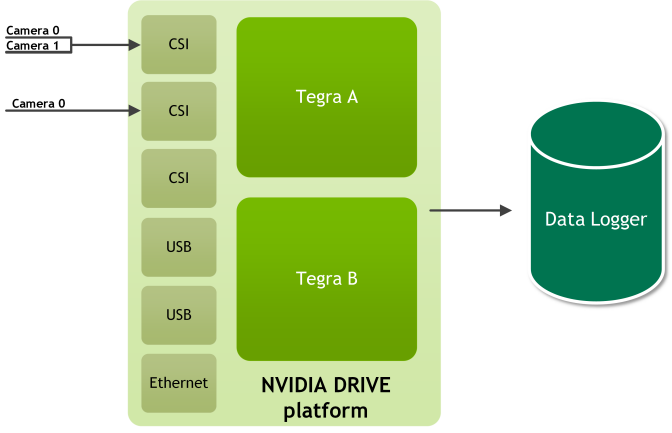
207 @warning Turn off the device before connecting or disconnecting a sensor.
209 #### To acquire data from three cameras
211 1. Turn on the device and open a terminal window.
212 2. On the target, navigate to:
214 /usr/local/driveworks/bin/
215 3. Run sample_camera_multiple_gmsl to verify that your camera is
216 correctly connected to the device. The following command is for cameras
217 connected at 0 and 1 on port-a and 0 on port-c:
219 ./sample_camera_multiple_gmsl --type-a=ar0231-rccb-bae-sf3324 --type-c=ar0231-rccb-bae-sf3324 \
220 --selector-mask=00110001
221 @warning Cameras must be connected to the port in ascending order (0, 1, 2, 3).
223 A window appears with video if the camera is correctly connected to the device.
224 Close the window to stop the camera application.
226 4. On the target, navigate to:
228 /usr/local/driveworks/tools/capture/
230 5. Copy the default configuration file in `configs/hyperion7_1/release.json`, and include the following
231 sensor block for camera. All the other sensor blocks can be removed.
234 "name": "camera:front:center:120fov",
235 "nominalSensor2Rig": {
248 "parameter": "camera-type=ar0231-rccb-bae-sf3324,camera-group=a,camera-count=2,siblingIndex=0,format=h264,output-format=yuv",
251 "bw-poly": "0.0 0.000545421498827636 -1.6216719633103e-10 -4.64720492990289e-12 2.85224527762934e-16",
257 "protocol": "camera.gmsl",
273 "name": "camera:front:right:120fov",
274 "nominalSensor2Rig": {
287 "parameter": "camera-type=ar0231-rccb-bae-sf3324,camera-group=a,camera-count=2,siblingIndex=1,format=h264,output-format=yuv",
290 "bw-poly": "0.0 0.000545421498827636 -1.6216719633103e-10 -4.64720492990289e-12 2.85224527762934e-16",
296 "protocol": "camera.gmsl",
312 "name": "camera:rear:center:120fov",
313 "nominalSensor2Rig": {
326 "parameter": "camera-type=ar0231-rccb-bae-sf3324,camera-group=c,camera-count=1,format=h264,output-format=yuv",
329 "bw-poly": "0.0 0.000545421498827636 -1.6216719633103e-10 -4.64720492990289e-12 2.85224527762934e-16",
335 "protocol": "camera.gmsl",
353 6. Save the modified configuration file.
355 7. Run the following command to log the data from the camera:
357 # ./recorder-tui <modified_file.json>
358 A TextUI interface appears on the console as below:
360 Recorder @ release: Ready to start
361 4.672 GB 1.591 MB/s camera:front:center:120fov
362 4.700 GB 1.585 MB/s camera:front:right:120fov
363 4.987 GB 2.035 MB/s camera:rear:center:120fov
364 14.359 GB 5.211 MB/s TOTAL
365 Last output: [19-8-2018 0:48:58] SensorManager: started
366 Press s<Enter> to start/stop. Press q<Enter> to quit.
368 After a few seconds, enter `s` to stop recording data.
370 @warning Stop recording data and then quite the application. If you quit the app
371 before you stop recording data, you will corrupt the acquired data.
373 The sensor data will be available on the ext4-formmated eSATA/USB SSD.
375 @subsection dwx_recording_devguide_basic_gps GPS
377 This section shows how to acquire data from a GPS sensor.
379 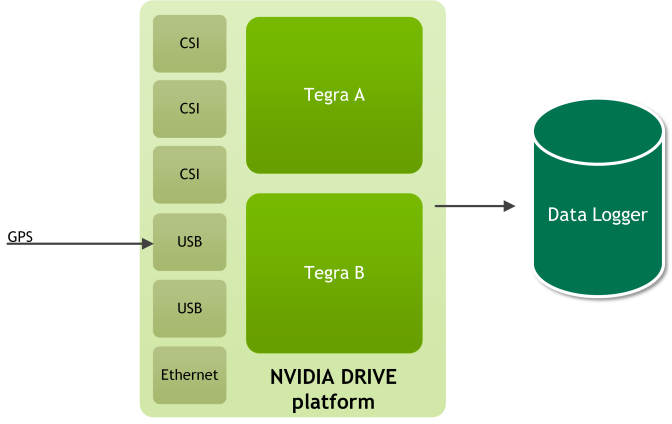
381 #### To determine GPS settings for the rig file
383 1. With the device powered off, connect the GPS sensor to the device per vendor
384 documentation. For example, Garmin connection instructions are on page 8 at:<br>
385 http://static.garmin.com/pumac/GPS_18x_Tech_Specs.pdf
386 2. Determine on which serial port the device is enumerated:
389 3. Determine the baud rate at which the GPS device transmits data. This
390 information can be obtained from vendor documentation. For example, Garmin LVC
391 GPS 18x uses 4800 baud.
392 4. Set the baud rate to the serial port. For example:
394 stty -F /dev/ttyUSB0 4800
395 5. Verify that GPS data is being received:
397 cat /dev/ttyUSB0 4800
398 6. Update the GPS settings in the rig file with the serial port and baud rate.
400 #### To acquire data from a GPS sensor
402 1. With the device powered off, connect the GPS sensor to the device.
403 @warning Turn off the device before connecting or disconnecting a sensor.
404 2. Turn on the device and open a terminal window.
405 3. On the target, navigate to:
408 4. Run the following command to verify that your GPS sensor is correctly connected to the device:
410 ./sample_gps_logger --driver=gps.uart --params=device=/dev/ttyUSB0,baud=4800
411 Console prints will display the data acquired if the GPS sensor is correctly
412 connected to the device and the drivers are running.
414 5. On the target, navigate to:
416 /usr/local/driveworks/tools/capture/
418 6. Copy the default configuration file in `configs/hyperion7_1/release.json`, and include the following
419 sensor block for gps. All the other sensor blocks can be removed.
422 "name": "gps:garmin",
423 "nominalSensor2Rig": {
436 "parameter": "device=/dev/ttyUSB0,baud=115200",
437 "protocol": "gps.uart",
454 8. Run the following command to log the data from the camera:
456 # ./recorder-tui <modified_file.json>
457 A TextUI interface appears on the console as below:
459 Recorder @ release: Ready to start
460 1.057 MB 25.591 KB/s gps:garmin
461 1.057 MB 25.591 KB/s TOTAL
462 Last output: [19-8-2018 0:48:58] SensorManager: started
463 Press s<Enter> to start/stop. Press q<Enter> to quit.
465 After a few seconds, enter `s` to stop recording data.
467 @warning Stop recording data and then quite the application. If you quit the app
468 before you stop recording data, you will corrupt the acquired data.
470 The sensor data will be available on the ext4-formmated eSATA/USB SSD.
472 @subsection dwx_recording_devguide_basic_lidar Lidar
474 This section shows how to acquire data from a Lidar sensor.
476 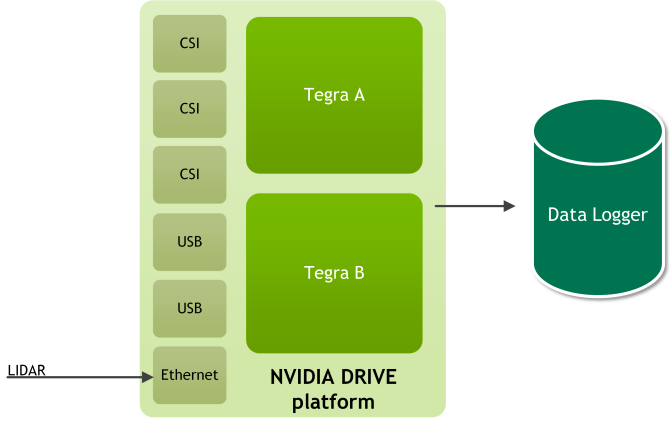
478 #### Determining the Lidar IP Address and Port
480 ##### To determine the IP address and port for a Quanergy LIDAR
482 1. Connect the Lidar Ethernet port to eth0 port of Xavier A.
483 2. Connect the Quanergy to a router switch and connect this router to Xavier A
484 eth0. The IP of router will be in range 192.168.x.x.
485 3. Find the IP address by running:
487 # nmap -sn 192.168.1.0/25
488 If Quanergy is detected, you will see an IP address associated with Quanergy system.
489 4. To obtain the port number, consult the Quanergy technical specification.
490 The following is an example of rig sensor block for a Quanergy LIDAR.
493 "name": "lidar:quanergy",
494 "nominalSensor2Rig": {
507 "parameter": "device=QUAN_M81A,ip=192.168.1.8,port=4141,scan-frequency=10",
508 "protocol": "lidar.socket",
525 ##### To determine the IP address for a Velodyne LIDAR
527 1. Connect the LIDAR to the eth0 port of Xavier A.
528 2. Obtain the default IP address and port number from the Velodyne technical specification.
529 3. Set up the IP of eth0 with:
531 # ifconfig eth0 <lidar_address>
532 By default, the Lidar IP address is 192.168.1.201.
533 Ensure this IP does not conflict with the AURIX, Xavier A, or Xavier B IPs.
534 The following is an example of recorder-config.json with a Velodyne 32 LIDAR.
537 "name": "lidar:velodyne",
538 "nominalSensor2Rig": {
551 "parameter": "device=VELO_HDL32E,ip=192.168.1.201,port=2368,scan-frequency=10",
552 "protocol": "lidar.socket",
568 The value for params above is:
570 "device=VELO_HDL32E,ip=192.168.1.201,port=2368,scan-frequency=10"
571 For Velodyne 16, the device name is VELO_VLP16.
572 For Velodyne 64, the device is VELO_HDL64E.
574 #### Recording Data from a Lidar Sensor
576 After you obtain the Lidar IP address and port, you can obtain Lidar data.
578 ##### To acquire data from a Lidar sensor
579 1. With the device powered off, connect the LIDAR sensor to the device.
580 @warning Turn off the device before connecting or disconnecting a sensor.
581 2. Turn on the device and open a terminal window.
582 3. On the target, navigate to:
585 4. Run the following command to verify that your LIDAR sensor is correctly
586 connected to the device. For example:
588 ./sample_lidar_replay --device=VELO_HDL32E --ip=192.168.1.201 --port=2368 \
590 A window appears that displays a point cloud if the LIDAR sensor is correctly
591 connected to the device and the drivers are running.
592 Close the window to stop the lidar replay application.
594 5. Go to the following location in the DriveWorks folder:
596 /usr/local/driveworks/tools/capture/
598 6. Copy the default configuration file in `configs/hyperion7_1/release.json`, and include the following
599 sensor block for lidar:
602 "name": "lidar:side",
603 "nominalSensor2Rig": {
616 "parameter": "ip=<ip_address>,port=<port>,device=<device_name>,frequency=10",
617 "protocol": "lidar.socket",
634 - `<ip_address>` is the IP address of the LIDAR sensor.
635 - `<port>` is the port for the Lidar sensor.
637 8. Run the following command to log the data from the camera:
639 # ./recorder-tui <modified_file.json>
640 A TextUI interface appears on the console as below:
642 Recorder @ release: Ready to start
643 50.057 MB 400.591 KB/s lidar:side
644 50.057 MB 400.591 KB/s TOTAL
645 Last output: [19-8-2018 0:48:58] SensorManager: started
646 Press s<Enter> to start/stop. Press q<Enter> to quit.
648 After a few seconds, enter `s`to stop recording data.
650 @warning Stop recording data and then quite the application. If you quit the app
651 before you stop recording data, you will corrupt the acquired data.
653 The sensor data will be available on the ext4-formmated eSATA/USB SSD.
655 @subsection dwx_recording_devguide_basic_multi Multiple Sensor Types
657 This section shows you how to acquire data from multiple sensors connected to
658 the device. This section assumes that you know how to verify that each sensor is
659 working and that you have a rig configuration file.
661 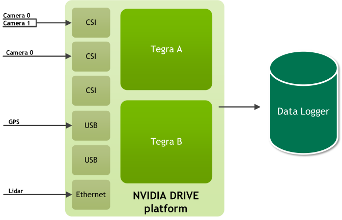
663 #### To acquire data from multiple cameras, an HDL-32 LIDAR, and a GPS Sensors
665 This procedure shows you how to log the data from the following sensors:
666 - Three AR0231 cameras
667 - One HDL-32 LIDAR sensor
670 The cameras are connected to the following ports:
672 |Camera Group | Port Name | Camera Type | Ports|
673 |-------------|-----------|-------------|------|
674 |A | a | ar0231-rccb-bae-sf3324 | Port 0<br>Port 1 |
675 |B | c | ar0231-rccb-bae-sf3324 | Port 0|
677 @warning Turn off the device before connecting or disconnecting a sensor.
679 1. Change the following sections in the configuration file to log the data from the sensors:
682 "name": "camera:front:center:120fov",
683 "nominalSensor2Rig": {
696 "parameter": "camera-type=ar0231-rccb-bae-sf3324,camera-group=a,camera-count=2,siblingIndex=0,format=h264,output-format=yuv",
699 "bw-poly": "0.0 0.000545421498827636 -1.6216719633103e-10 -4.64720492990289e-12 2.85224527762934e-16",
705 "protocol": "camera.gmsl",
721 "name": "camera:front:right:120fov",
722 "nominalSensor2Rig": {
735 "parameter": "camera-type=ar0231-rccb-bae-sf3324,camera-group=a,camera-count=2,siblingIndex=1,format=h264,output-format=yuv",
738 "bw-poly": "0.0 0.000545421498827636 -1.6216719633103e-10 -4.64720492990289e-12 2.85224527762934e-16",
744 "protocol": "camera.gmsl",
760 "name": "camera:rear:center:120fov",
761 "nominalSensor2Rig": {
774 "parameter": "camera-type=ar0231-rccb-bae-sf3324,camera-group=c,camera-count=1,format=h264,output-format=yuv",
777 "bw-poly": "0.0 0.000545421498827636 -1.6216719633103e-10 -4.64720492990289e-12 2.85224527762934e-16",
783 "protocol": "camera.gmsl",
799 "name": "gps:garmin",
800 "nominalSensor2Rig": {
813 "parameter": "device=/dev/ttyUSB0,baud=115200",
814 "protocol": "gps.uart",
830 "name": "lidar:side",
831 "nominalSensor2Rig": {
844 "parameter": "ip=<ip_address>,port=<port>,device=<device_name>,frequency=10",
845 "protocol": "lidar.socket",
862 - `<ip_address>` is the IP address of the LIDAR sensor.
863 - `<port>` is the port for the LIDAR sensor.
865 Save the modified configuration file.
867 2. Run the following command to log the data from the sensors:
869 # ./recorder-tui <modified_file.json>
870 A TextUI interface appears on the console as below:
872 Recorder @ release: Ready to start
873 4.672 GB 1.591 MB/s camera:front:center:120fov
874 4.700 GB 1.585 MB/s camera:front:right:120fov
875 4.987 GB 2.035 MB/s camera:rear:center:120fov
876 1.057 MB 25.591 KB/s gps:garmin
877 50.057 MB 400.591 KB/s lidar:front
878 14.410 MB 6.137 MB/s TOTAL
879 Last output: [19-8-2018 0:48:58] SensorManager: started
880 Press s<Enter> to start/stop. Press q<Enter> to quit.
882 After a few seconds, enter `s`to stop recording data.
884 @warning Stop recording data and then quite the application. If you quit the app
885 before you stop recording data, you will corrupt the acquired data.
887 The sensor data will be available on the ext4-formmated eSATA/USB SSD.
889 @section dwx_recording_devguide_basic_sensor_data_quality Sensor Data Quality
891 #### To sanity-check the Lidar and Camera data
892 1. Use the recorder tool to capture Lidar and camera data on someone walking past.
893 2. Use the replayer tool on the captured data to verify that:
894 - Data from the different sensors are roughly in sync and
895 - Lidar data makes sense (i.e. the shape of the person walking past).
897 #### To sanity-check the Lidar data
898 - For Lidar, compare the Lidar plot coming from the PDK with the reference plots
899 obtained from any other Linux x86 machine, at the same location.
901 #### To sanity-check GPS data
902 - If you are testing in a Lab, ensure the GPS produces the same coordinates over
903 time. It should be roughly the same because it is not moving.
905 #### To determine if a sensor is broken
906 - Feed each offline file to the corresponding DriveWork sensor sample. If one of
907 the files fails, you know there is a problem with the sensor.
908 - Read the documentation provided by the sensor manufacturer.