- Note
- This tool is available in both NVIDIA DriveWorks and NVIDIA DRIVE Software releases.
This tool is available on the x86 Host System and NVIDIA DRIVE™ OS Linux.
The GUI recording tool builds on top of the TextUI Recording Tool, but provides a graphical user interface for operation and visualizing sensor status.
Starting the Recording Application
Run this tool by executing:
cd /usr/local/driveworks/tools/capture
./recorder-qtgui <rig file> OR <rig_directory>
Using the Interface
The home screen of the recorder GUI is composed of several parts as illustrated in the following screenshot.
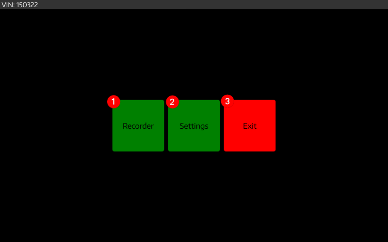
Recorder
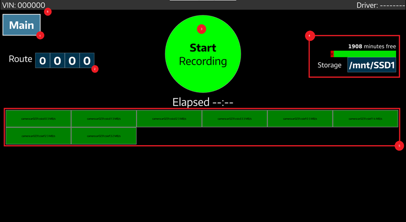
The main screen of the recorder GUI is composed of several parts as illustrated in the following screenshot:
- Main button to return to Home screen.
- Route setting drop boxes.
- Start Recording control button.
- Storage Status info.
- Sensor Status.
- VIN info.
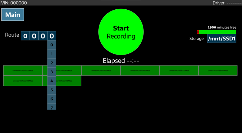
Route
The route can be set by selecting numbers from the 4 drop boxes. This semantics of route are user-defined, but a file containing this route number will be included in the recording.
Start Recording
When you press the Record button, the application starts recording and the Start button is replaced by a Stop Recording button.
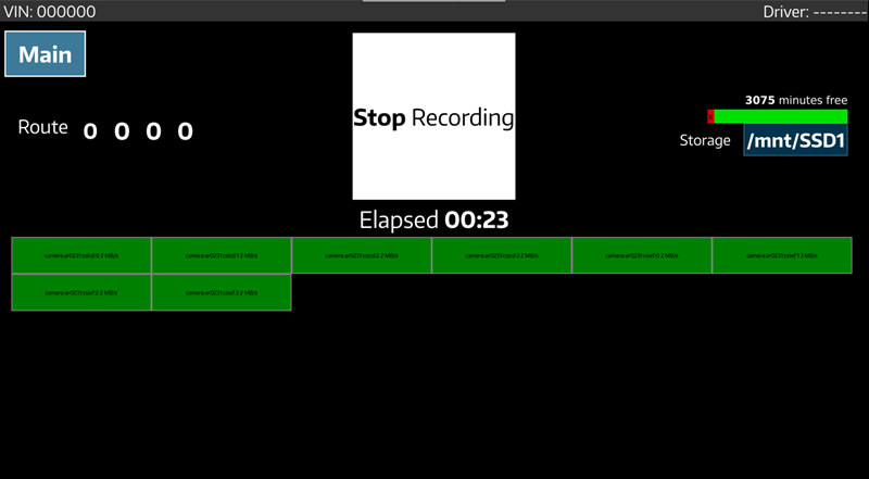
The Elapsed time item marked in the picture indicates the time elapsed since the start of the recording. Pressing the RECORD button again stops the current recording procedure.
- Note
- The RECORD button will be disabled with the message
Disk Full/No Diskin case no valid storage medium is found or the available disks are full. -
The RECORD button will be disabled with the message
Failurein case one of the sensor initialization fails during startup. The log to diagnose the failure can be found on the console.
Sensor Status
If sensor initialization succeeds, a block for the sensor containing its name is added to the grid in the recoder window. These blocks also indicate the data rate (measured at disk sink) for that sensor. The color of this block is used to indicate the status - green and red, respectively.
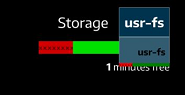
Storage Status
The Storage field shows the storage usage, including:
- Total free percentage.
- Estimated remaining recording time.
- Usage of each available storage device.
The selection of storage device for the current recording can be made by opening the storage drop box, as shown below.
Settings
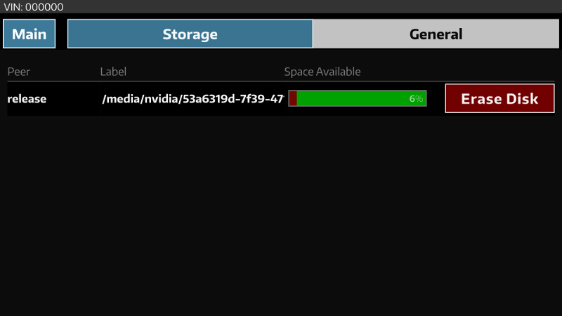
Storage Management
This screen allows one to erase disk volumes that are connected to the device. In a distributed recording environment, this screen has capability to erase disks on all slave devices, as well.
VIN selection
On the general setting page, the last 6 digits of the VIN number can be selected, and will be in a file in the recording folder.
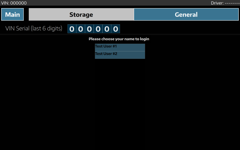
Driver selection
On the general settings page, the name of the driver performing the recording can be selected from a list. This will be included as part of the metadata file (named "aux_info") that is stored in the recording folder.
The list of available driver names is specified in a text file, named "login.txt". This file should contain a single driver name per line, as shown in the example below:
Test Driver #1
Test Driver #2
The "login.txt" file shall be placed in the same directory as the rig configuration file. In case a rig_directory is used, place this file in the rig_directory.