1 # Copyright (c) 2019-2020, NVIDIA CORPORATION. All rights reserved.
3 @page calibration_usecase_radar Radar Self-Calibration
5 @note SW Release Applicability: This tutorial is applicable to modules in both **NVIDIA DriveWorks** and **NVIDIA DRIVE Software** releases.
7 ## Radar Calibration - Operating Principle
9 Radar calibration estimates the current sensor orientation (yaw angle) with
10 respect to the vehicle's coordinate frame. This yaw angle is estimated by first
11 using the Doppler signal of radar detections to estimate the radar's motion.
12 Subsequently, the radar motion is matched with vehicle yawrate estimates to estimate
13 the yaw angle. Calibration measurements require a sufficiently large speed of
16 The Doppler motion observed by a radar can also be used to calibrate odometry
17 speed factors, i.e., a factor which maps measured longitudinal speed to the
18 actual driven speed. In addition the method can be used to calibration
19 individual wheel radii by looking for the radius which maps wheel's rotational
20 velocity to the longitudinal velocity measured by radar. If requested, this
21 calibration will be performed during straight driving maneuvers.
23 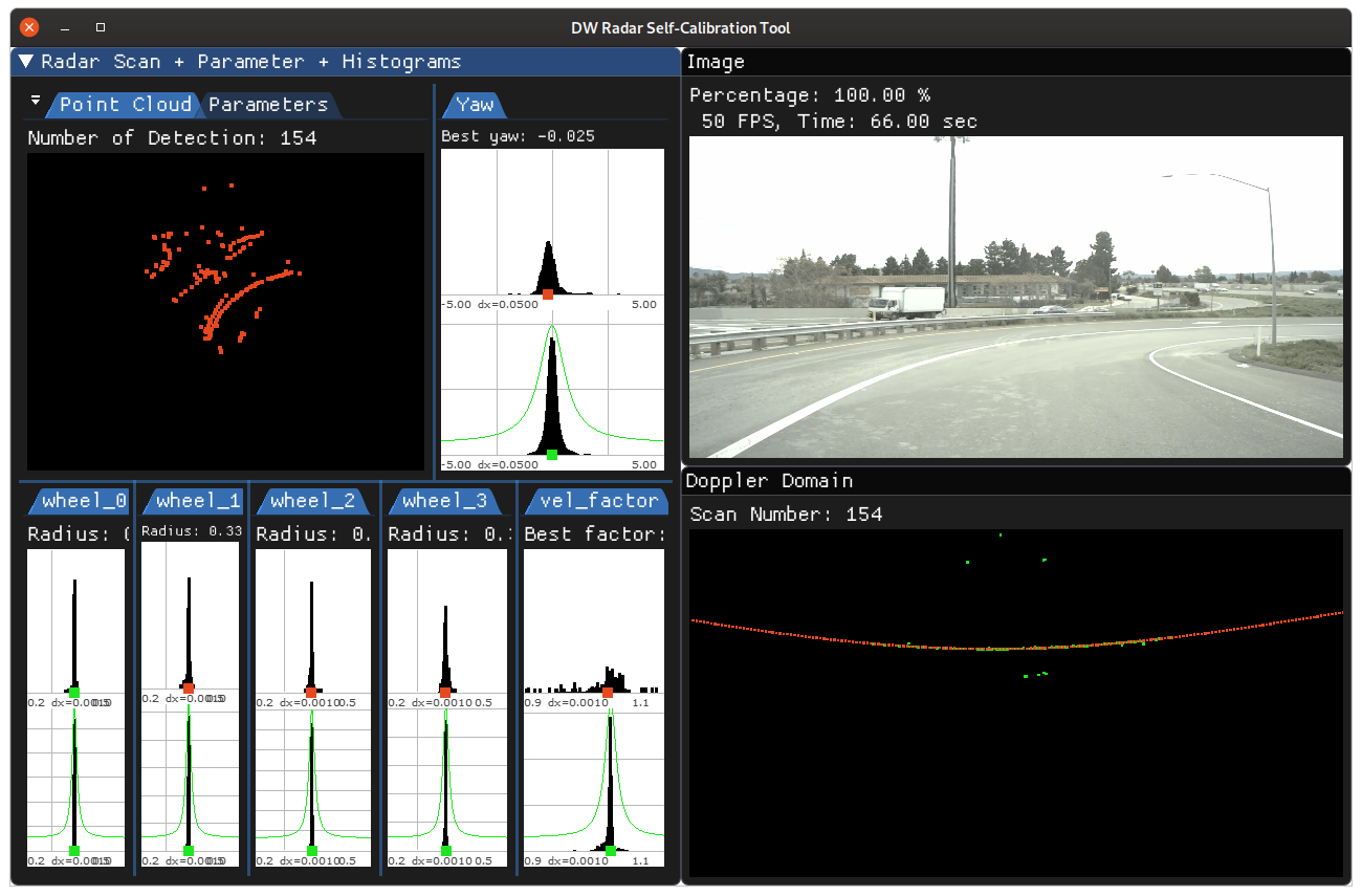
27 ### Initialization Requirements
29 - Nominal values on radar calibration
30 - Orientation(roll/pitch/yaw): less than 10 degree error
31 - Position(x/y/z): x and y are not used for now, z is less than 10 cm error
33 ### Input Requirements
35 - Sensors: radar calibration requires data from radar and CAN sensors.
36 - dwVehicleIOState: to perform radar calibration, dwCalibrationEngine has to be fed with `dwVehicleIOState`, with information parsed from received CAN events.
37 - Assumption: Vehicle performs normal driving maneuvers until calibration convergence.
40 ### Output Requirements
42 - Corrected yaw value: less than 0.1 degrees
43 - Time to correction: less than 2 minutes for radar sensor with 15HZ spinning frequency
45 ## Cross-validation KPI
47 Several hours of data are used to produce a reference calibration value for
48 cross-validation. Then, short periods of data are evaluated for whether they can
49 recover the same values. For example, the graph below shows precision/recall
50 curves of radar self-calibration.
51 Precision indicates that an accepted calibration is within a fixed precision threshold
52 from the reference calibration, and recall indicates the ratio of accepted calibrations
53 in the given amount of time.
55 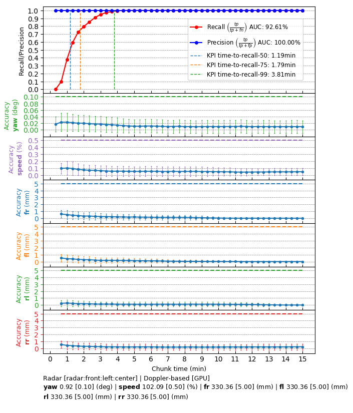
59 The following code snippet shows the general structure of a program that performs Radar self-calibration
62 dwCalibrationEngine_initialize(...); // depends on sensor from rig configuration module
63 dwCalibrationEngine_initializeRadar(...); // depends on nominal calibration from rig configuration
64 dwCalibrationEngine_startCalibration(...); // runtime calibration dependencies need to be met
66 while (true) // main loop
68 // code to get CAN measurement
69 // code to add vehicle IO state to calibration engine
70 dwCalibrationEngine_addVehicleIOState(...);
72 // code to get radar motion
73 dwRadarDopplerMotion_getMotion(...);
75 // feed radar sweep into self-calibration
76 dwCalibrationEngine_addRadarDopplerMotion(...);
78 // retrieve calibration status
79 dwCalibrationStatus status;
80 dwCalibrationEngine_getCalibrationStatus(&status, ...);
82 // retrieve self-calibrated result
83 if (status == DW_CALIBRATION_STATE_ACCEPTED)
86 dwTransformation3f radar2rig;
87 dwCalibrationEngine_getSensorToRigTransformation(&radar2rig, ...);
89 // odometry speed factor
90 float32_t speedFactor;
91 dwCalibrationEngine_getOdometrySpeedFactor(&speedFactor, ...);
94 for (auto w : {DW_VEHICLE_WHEEL_FRONT_LEFT,
95 DW_VEHICLE_WHEEL_FRONT_RIGHT,
96 DW_VEHICLE_WHEEL_REAR_LEFT,
97 DW_VEHICLE_WHEEL_REAR_RIGHT})
100 dwCalibrationEngine_getVehicleWheelRadius(&radius, w, ...);
105 dwCalibrationEngine_stopCalibration(...);
108 This workflow is demonstrated in the following sample: @ref dwx_radar_calibration_sample