1 # Copyright (c) 2019-2020 NVIDIA CORPORATION. All rights reserved.
3 @page calibration_usecase_stereo Epipolar-based Stereo Self-Calibration
5 @note SW Release Applicability: This tutorial is applicable to modules in both **NVIDIA DriveWorks** and **NVIDIA DRIVE Software** releases.
9 Given a horizontal stereo rig, the right camera's extrinsic pose calibration
10 with respect to the left camera is represented by both orientation and position
13 Orientation parameters are defined as roll, pitch and yaw, while position
14 parameters are defined as x, y, z. The orientation parameters identify the
15 rotation that aligns the right camera orientation to the left camera
16 orientation. The position parameters identify the translation between the right
17 camera position and the left camera position. All six parameters are crucial in
18 tasks such as stereo rectification and disparity estimation that rely on the
19 relative pose of the right camera with respect to the left camera.
21 NVIDIA<sup>®</sup> DriveWorks uses visually matched features to calibrate
22 the right camera's orientation and position in a self-calibration setting. While
23 orientation is calibrated fully, position is only calibrated up to norm, i.e.,
24 up to the relative translation between the two cameras specified in the rig
25 file. All six parameters are calibrated simultaneously by estimating the
26 transformation that best satisfies the epipolar constraint on the feature
29 ### Right Camera Roll / Pitch / Yaw / X / Y / Z
31 The features obtained from the left image are matched to those obtained from the
32 right image. Using the well-known epipolar constraint, the relative
33 transformation between the left and the right camera is estimated. This relative
34 transformation provides roll, pitch, yaw, as well as x, y, z components of the
35 right camera with respect to the left camera.
37 The instantaneous calibration for an image pair is accumulated in histograms for
38 the calibration's roll, pitch, yaw, x, y, z components to estimate a final
39 calibration in a robust way.
41 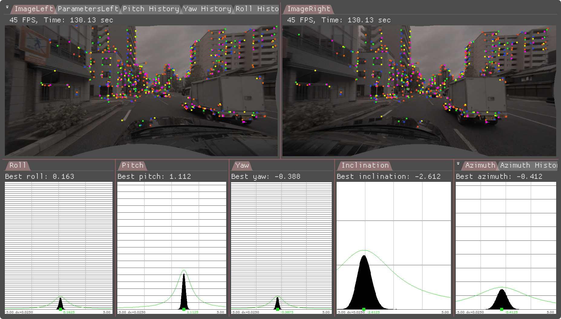
45 ### Initialization Requirements
47 - Nominal values on camera calibration
48 - Orientation(roll/pitch/yaw): roll/pitch/yaw less than 5 degree error
49 - Position(x/y/z): less than 10 mm
50 - Intrinsic calibration: accurate to 0.5 pixel
52 ### Runtime Calibration Dependencies
54 - IMU-based egomotion needs to be based on accurate IMU calibration and odometry properties
56 ### Input Requirements
58 - Assumption: feature matches (right-to-left) compatible with DriveWork's module @ref imageprocessing_features_mainsection
60 ### Output Requirements
62 - Corrected calibration for roll/pitch/yaw/x/y/z (mandatory)
63 - Correction accuracy:
64 + roll/yaw: less than 0.10deg error
65 + pitch: less than 0.2deg error
66 + x/y/z: less than 2cm error
67 - Time/Events to correction:
68 + roll/pitch/yaw/x/y/z: less than 0:27 minutes in 75% of the cases, less than 0:49 minutes in 100% of the cases
70 ## Cross-validation KPI
72 Several hours of data are used to produce a reference calibration value for
73 cross-validation. Then, short periods of data are evaluated for whether they can
74 recover the same values. For example, the graph below shows precision/recall
75 curves of stereo self-calibration.
76 Precision indicates that an accepted calibration is within a fixed precision threshold
77 from the reference calibration, and recall indicates the ratio of accepted calibrations
78 in the given amount of time.
80 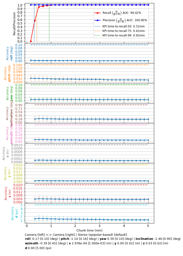
84 The following code snippet shows the general structure of a program that performs stereo self-calibration
87 dwFeatureHistoryArray matchesHistoryGPU; // used by the features module
88 dwFeatureArray matchesDetectedGPU; // used by the features module
90 dwCalibrationEngine_initialize(...); // depends on sensors from rig configuration module
91 dwCalibrationEngine_initializeStereo(...); // depends on nominal calibrations from rig configuration.
92 dwCalibrationEngine_startCalibration(...); // runtime calibration dependencies need to be met
94 while(true) // main loop
96 // track features for current left camera frame
97 dwFeature2DTracker_trackFeatures(matchesHistoryGPU, ..., matchesDetectedGPU, ...);
99 // detect features for current left camera frame
100 dwFeature2DDetector_detectFromPyramid(matchesDetectedGPU, ...);
102 // track features for current right camera frame
103 dwFeature2DTracker_trackFeatures(matchesHistoryGPU, ..., matchesDetectedGPU, ...);
105 // detect features for current right camera frame
106 dwFeature2DDetector_detectFromPyramid(matchesDetectedGPU, ...);
108 // feed feature matches into self-calibration
109 dwCalibrationEngine_addMatches(matchesHistoryGPU, ...);
111 // retrieve calibration status
112 dwCalibrationEngine_getCalibrationStatus(...);
114 // retrieve self-calibration results
115 dwCalibrationEngine_getSensorToSensorTransformation(...);
118 dwCalibrationEngine_stopCalibration(...);
121 This workflow is demonstrated in the following sample: @ref dwx_stereo_calibration_sample