Lidar Calibration - Operating Principle
Lidar calibration estimates the current sensor orientation (roll, pitch, yaw) and height with respect to the vehicle coordinate frame. Roll, pitch and height are estimated via fitting a ground plane near the vehicle. Yaw and pitch are estimated via aligning the vehicle egomotion with the Lidar sensor motion in the same time interval. Calibration will stop once the vehicle drives in a speed lower than 5 km/h. It will resume once the vehicle drives faster than that speed limit. Current estimation targets at multi-beam 360 degree rotational Lidar sensors, i.e. Velodyne-HDL32E and Velodyne-HDL64E.
Lidar Roll/Pitch/Yaw/Height
Current roll/pitch/height estimation is not suitable for Lidar sensor with low density and narrow horizontal field-of-view, i.e. Velodyne-VLP16 and IBEO-LUX4. The estimation inputs a full Lidar sweep and expects sufficient cloud of points in the vehicle vicinity. Such Region-Of-Interest (rectangular ROI) is defined by the vehicle physical specifications and nominal sensor calibration. In the ROI, the method selects 3D Lidar points whose heights are within a certain threshold for ground plane fitting and optimization. The estimated ground plane normal vector is used to compute the roll and pitch corrections with respect to the nominal sensor coordinate frame. The ground plane's distance to the sensor coordinate origin defines the actual height.
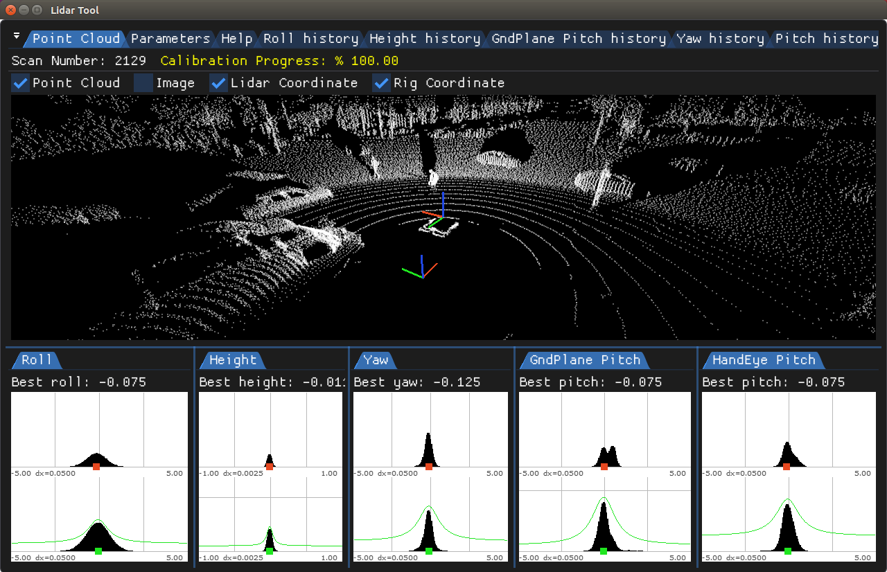
Yaw can not be determined by ground plane fitting. It requires extra information such as vehicle presents circular trajectory while driving. Hand-eye optimization aligns vehicle relative pose with Lidar point cloud relative poses between two timestamps. The optimization outputs yaw/pitch angles. Those estimates (roll/pitch/height and yaw/pitch) are inserted into robust estimation histograms over time. After the estimates are accepted, their modes define the best estimations. Pitch is considered to be accepted only if the two pitch estimates (hand-eye and ground-plane-based) agree with each other within small threshold (see histograms below).
Requirements
Initialization Requirements
- Nominal values on Lidar calibration
- Orientation(roll/pitch/yaw): less than 10 degree error
- Position(x/y/z): x and y are not used for now, z is less than 10 cm error
- Vehicle physical dimenstions: wheel base, vehicle width and length
Runtime Calibration Dependencies
- If using IMU-based egomotion in the pose-based API, then egomotion needs to be based on accurate IMU calibration
Input Requirements
- Assumption: Vehicle performs the aforementioned maneuvers until calibration convergence.
- Vehicle egomotion: requirements can be found in the Egomotion module
- Sensors: in order to achieve good performance, Lidar calibration requires data from IMU, GPS, CAN sensors.
Output Requirements
- Corrected roll/pitch/yaw value: less than 0.3 degrees
- Corrected height value: less than 3 cm
- Time to correction: less than 10 minutes for Lidar sensor with 10HZ spinning frequency
Cross-validation KPI
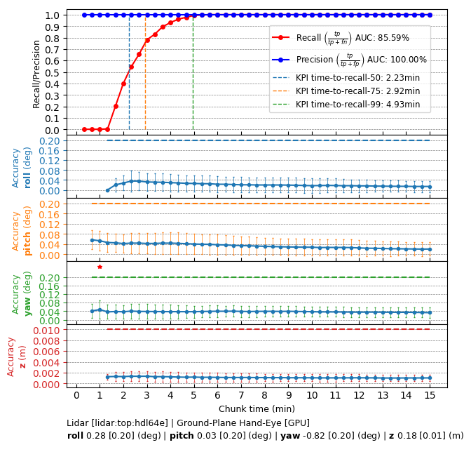
Several hours of data are used to produce a reference calibration value for cross-validation. Then, short periods of data are evaluated for whether they can recover the same values. For example, the graph below shows precision/recall curves of Lidar self-calibration. Precision indicates that an accepted calibration is within a fixed precision threshold from the reference calibration, and recall indicates the ratio of accepted calibrations in the given amount of time.
Workflow
The following code snippet shows the general structure of a program that performs Lidar self-calibration
This workflow is demonstrated in the following sample: Lidar Calibration Sample