Table of Contents
The DriveWorks SDK defines multiple coordinate systems, given by dwCoordinateSystem. The following sections describe the conventions for each coordinate system.
Vehicle Coordinate Systems
Vehicle coordinate systems are used to determine vehicle parameters, sensor placement and pose of objects in the environment relative to the vehicle. Coordinate systems for a set of rigid bodies of a vehicle are described below.
Base Vehicle Coordinate System
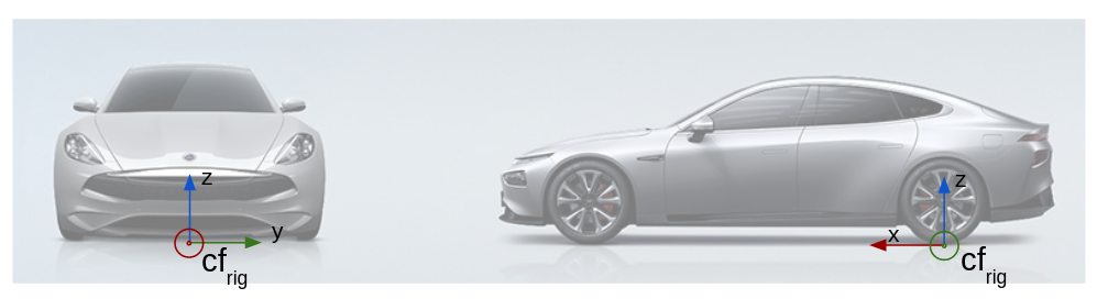
The Base Vehicle Coordinate System is the coordinate system attached to the primary vehicle body supported by suspension. The axis system is fixed in the body such that, in nominal resting condition on horizontal ground, the X axis is horizontal, parallel to the vehicle's longitudinal plane of symmetry and pointing forwards. The Y axis is horizontal, perpendicular to the X axis and pointing to the left, and the Z axis is vertical, perpendicular to both X and Y and pointing upwards. The origin is fixed in the body and chosen as the mid-point of the (virtual) rear-axle, projected onto ground. See ISO8855:2011(2.10, 2.12).
Currently, the Base Vehicle Coordinate System is the one that dwRig relies on to describe all sensor positions. Future extensions will allow placement of sensors relative to other vehicle bodies.
- Note
- In a passenger car configuration, the Base Vehicle Coordinate System refers to the car body, and is often simply referred to as the "rig".
- In a truck configuration, the Base Vehicle Coordinate System refers to the tractor chassis.
Vehicle Cabin Coordinate System
The Vehicle Cabin Coordinate System is the coordinate system attached to the cabin body suspended above the primary vehicle body (see Base Vehicle Coordinate System). The axis system is fixed in the cabin body such that, in nominal resting condition, the X axis is horizontal, parallel to the cabin's longitudinal plane of symmetry and pointing forwards. The Y axis is horizontal, perpendicular to the X axis and pointing to the left, and the Z axis is vertical, perpendicular to both X and Y and pointing upwards. The cabin origin is fixed in the body and chosen such that it coincides with the origin of DW_COORDINATE_SYSTEM_VEHICLE_BASE in nominal resting conditions. See ISO8855:2011(2.18, 2.19).
- Note
- The Base Vehicle Coordinate System only applies to vehicles with a suspended cabin.
Vehicle Trailer Coordinate System
The Vehicle Trailer Coordinate System is the coordinate system attached to each of the vehicle units towed by a leading vehicle. Axis systems and origins are defined by the same logic as applied for the Base Vehicle Coordinate System. See ISO8855:2011(3.2).
World Coordinate Systems
Various World Coordinate Systems are used depending on context and are described below.
Roadplane Coordinate System
The Roadplane Coordinate System is the coordinate system attached to the plane approximating the surface supporting the primary vehicle unit. The axis system is fixed in the plane such that X and Y are aligned with the projection onto the plane of axes X and Y of the primary vehicle unit (see Base Vehicle Coordinate System). The Z axis is perpendicular to the plane and pointing upwards. The road plane origin is chosen such that it coincides with the projection of the origin of the Base Vehicle Coordinate System onto the plane.
Local Coordinate System
The Local Coordinate System is a coordinate system with origin at an arbitrary point in the world. The axis system is defined by the local vertical, local horizontal (LVLH) and is arbitrarily rotated relative to ENU. Origin and axis are typically defined by the vehicle position and heading at a particular point in time, e.g. at initialization.
World Coordinate System
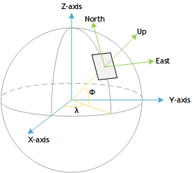
The World Coordinate System is used for map/earth coordinates and is defined by the World Geodetic System 1984 (WGS84) and East-North-Up (ENU) axis conventions.
The origin is defined at an arbitrary point on the Earth surface. X, Y and Z axes are defined tangent to the plane at origin point such that (X, Y, Z) corresponds to (East, North, Up).
The NVIDIA® DriveWorks maps module provides helper functions to transform into local Cartesian coordinates.
Sensor Coordinate System
The sensor coordinate system refers to the local coordinate system defined for each sensor. Conventions used in the SDK vary from sensor to sensor and are described below.
Image and Camera Coordinate Systems
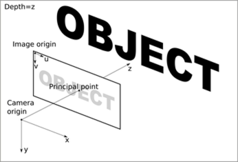
The Image Coordinate System describes the position of points in the image space, and the Camera Coordinate System describes the corresponding point in 3D space. The intrinsics of the camera are used to transform a point between the two coordinate systems.
The Image Coordinate System originates at the top-left of the image. The u- and v-axes, in pixel units, are aligned with the way pixels are stored in memory.
The Camera Coordinate System has its origin at the optical center of the camera. The x-axis points to the right of the image plane and the y-axis points to the bottom of the image plane. The z-axis points forward, along the optical axis. The x- and y-axes point in the same direction as the image u- and v-axes, respectively. The camera coordinate axes are in metric units.
IMU Coordinate System
DriveWorks IMU Coordinate Systems are dependent on the IMU manufacturer and model, see below. Associated GPS positions need to be provided as a 3D position vector expressed in IMU Coordinate System.
Continental
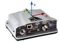
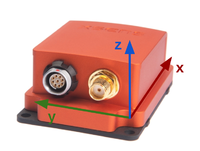
The Continental IMU Coordinate System is centered as in the figure below. The x-axis points in the direction opposite of the connector / plug. The z-axis points towards the top of the sensor. The y-axis is oriented such that it completes an orthogonal right-handed coordinate system.

Novatel
The Novatel IMU Coordinate System is centered as in the figure below. The y-axis points in the direction opposite of the connector / plug. The z-axis points towards the top of the sensor. The x-axis is oriented such that it completes an orthogonal right-handed coordinate system.
Xsens
The Xsens IMU Coordinate System is centered as in the figure below. The x-axis points in the direction opposite of the connector / plug. The z-axis points towards the top of the sensor. The y-axis is oriented such that it completes an orthogonal right-handed coordinate system.
LIDAR Coordinate System
DriveWorks LIDAR Coordinate Systems are dependent on the LIDAR manufacturer and model.
HESAI Tech
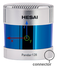
The HESAI Lidar Coordinate System is centered at the geometric center of the sensor's receptor. The x-axis points in the direction opposite of the connector / plug. The z-axis is collinear with the sensor's spinning axis, pointing in direction of the top of the sensor. The y-axis is oriented such that it completes an orthogonal right-handed coordinate system.
Velodyne Lidar
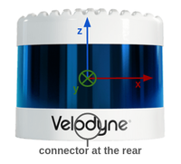
The Velodyne Lidar Coordinate System is centered at the geometric center of the sensor's receptor. The y-axis points in the direction of the connector / plug. The z-axis is collinear with the sensor's spinning axis, pointing in direction of the top of the sensor. The x-axis is oriented such that it completes an orthogonal right-handed coordinate system.
Radar Coordinate System
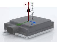
The Radar Coordinate System is centered at the geometric center of the radar's receptor. The x-axis points in sensing direction. The y-axis points in the direction of the connector / plug and the z-axis is oriented such that it completes an orthogonal right-handed coordinate system.
Custom Coordinate System
The Custom Coordinate System represents any arbitrary coordinate system that the developer wants to use. It is the developer's responsibility to keep other users informed of the relations between this coordinate system and any of the DriveWorks-defined coordinate systems.