1 # Copyright (c) 2019-2020 NVIDIA CORPORATION. All rights reserved.
3 @page calibration_usecase_stereo Epipolar-based Stereo Self-Calibration
7 Given a horizontal stereo rig, the right camera's extrinsic pose calibration
8 with respect to the left camera is represented by both orientation and position
11 Orientation parameters are defined as roll, pitch and yaw, while position
12 parameters are defined as x, y, z. The orientation parameters identify the
13 rotation that aligns the right camera orientation to the left camera
14 orientation. The position parameters identify the translation between the right
15 camera position and the left camera position. All six parameters are crucial in
16 tasks such as stereo rectification and disparity estimation that rely on the
17 relative pose of the right camera with respect to the left camera.
19 NVIDIA<sup>®</sup> DriveWorks uses visually matched features to calibrate
20 the right camera's orientation and position in a self-calibration setting. While
21 orientation is calibrated fully, position is only calibrated up to norm, i.e.,
22 up to the relative translation between the two cameras specified in the rig
23 file. All six parameters are calibrated simultaneously by estimating the
24 transformation that best satisfies the epipolar constraint on the feature
27 ### Right Camera Roll / Pitch / Yaw / X / Y / Z
29 The features obtained from the left image are matched to those obtained from the
30 right image. Using the well-known epipolar constraint, the relative
31 transformation between the left and the right camera is estimated. This relative
32 transformation provides roll, pitch, yaw, as well as x, y, z components of the
33 right camera with respect to the left camera.
35 The instantaneous calibration for an image pair is accumulated in histograms for
36 the calibration's roll, pitch, yaw, x, y, z components to estimate a final
37 calibration in a robust way.
39 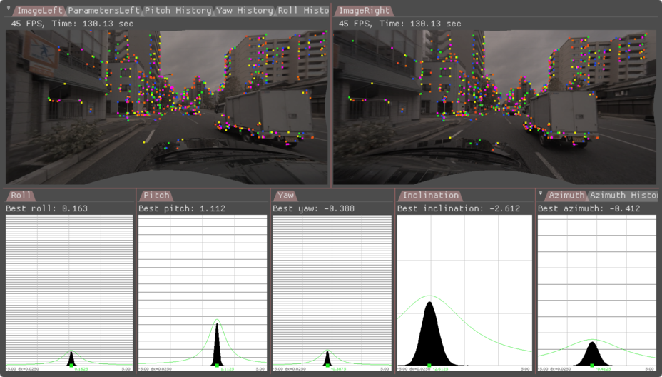
43 ### Initialization Requirements
45 - Nominal values on camera calibration
46 - Orientation(roll/pitch/yaw): roll/pitch/yaw less than 5 degree error
47 - Position(x/y/z): less than 10 mm
48 - Intrinsic calibration: accurate to 0.5 pixel
50 ### Runtime Calibration Dependencies
52 - IMU-based egomotion needs to be based on accurate IMU calibration and odometry properties
54 ### Input Requirements
56 - Assumption: feature matches (right-to-left) compatible with DriveWork's module @ref imageprocessing_features_mainsection
58 ### Output Requirements
60 - Corrected calibration for roll/pitch/yaw/x/y/z (mandatory)
61 - Correction accuracy:
62 + roll/yaw: less than 0.10deg error
63 + pitch: less than 0.2deg error
64 + x/y/z: less than 2cm error
65 - Time/Events to correction:
66 + roll/pitch/yaw/x/y/z: less than 0:27 minutes in 75% of the cases, less than 0:49 minutes in 100% of the cases
68 ## Cross-validation KPI
70 Several hours of data are used to produce a reference calibration value for
71 cross-validation. Then, short periods of data are evaluated for whether they can
72 recover the same values. For example, the graph below shows precision/recall
73 curves of stereo self-calibration.
74 Precision indicates that an accepted calibration is within a fixed precision threshold
75 from the reference calibration, and recall indicates the ratio of accepted calibrations
76 in the given amount of time.
78 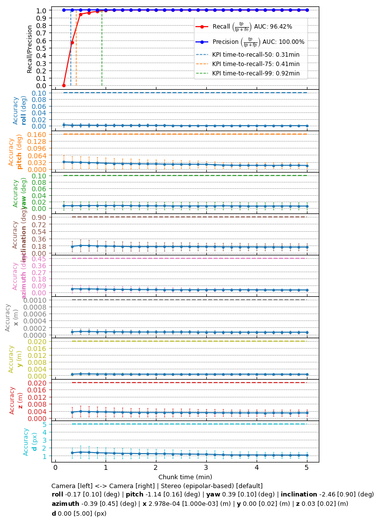
82 The following code snippet shows the general structure of a program that performs stereo self-calibration
85 dwFeatureHistoryArray matchesHistoryGPU; // used by the features module
86 dwFeatureArray matchesDetectedGPU; // used by the features module
88 dwCalibrationEngine_initialize(...); // depends on sensors from rig configuration module
89 dwCalibrationEngine_initializeStereo(...); // depends on nominal calibrations from rig configuration.
90 dwCalibrationEngine_startCalibration(...); // runtime calibration dependencies need to be met
92 while(true) // main loop
94 // track features for current left camera frame
95 dwFeature2DTracker_trackFeatures(matchesHistoryGPU, ..., matchesDetectedGPU, ...);
97 // detect features for current left camera frame
98 dwFeature2DDetector_detectFromPyramid(matchesDetectedGPU, ...);
100 // track features for current right camera frame
101 dwFeature2DTracker_trackFeatures(matchesHistoryGPU, ..., matchesDetectedGPU, ...);
103 // detect features for current right camera frame
104 dwFeature2DDetector_detectFromPyramid(matchesDetectedGPU, ...);
106 // feed feature matches into self-calibration
107 dwCalibrationEngine_addMatches(matchesHistoryGPU, ...);
109 // retrieve calibration status
110 dwCalibrationEngine_getCalibrationStatus(...);
112 // retrieve self-calibration results
113 dwCalibrationEngine_getSensorToSensorTransformation(...);
116 dwCalibrationEngine_stopCalibration(...);
119 This workflow is demonstrated in the following sample: @ref dwx_stereo_calibration_sample