Emitters
Emitters are the mechanism to create activity in a Flow grid. The shape of an emitter is currently established using PhysX collision shapes. Parameters for the emitter are set using a Flow emitter component.
Creating an Emitter
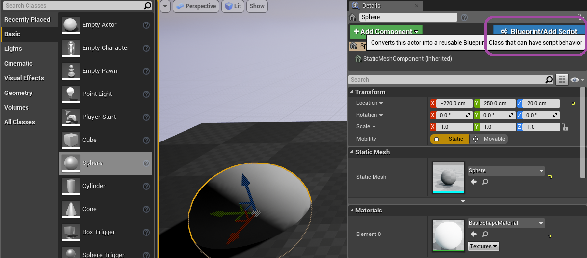
To create a basic sphere emitter, drag a sphere into the level. Select that sphere, and in the details pane, click the Blueprint/Add Script button to create a blueprint that includes a sphere component.
Once the blueprint has been named, an editor window for the blueprint will open. In the Components pane, click Add Component and select Flow Emitter. Clicking on the new Flow Emitter component will show available parameters in the details pane.

In the blueprint editor, select the StaticMeshComponent (Inherited). In the details pane, go the collision section. Set the Collision Presets to Custom..., and set the Flow channel to Overlap in the Collision Response.

Drag this new emitter blueprint into the level, inside the extents of a Flow grid.
Tuning an Emitter
The emitter velocity, density, temperature, and fuel settings are all target values that the user would like grid cells to move towards. The rate at which the emitter moves a grid cell towards the target value is controlled by the product of the couple rate and per channel masks. Higher couple rates move towards the target values in a shorter amount of time. This property is useful for moving objects. Lower couple rates can be very useful for stationary objects, since the weaker influence on the simulation allows simulation to happen naturally instead the emitter.
Due to the couple rate properties, in practice, good results are achieved by increasing couple rate via UE4 blueprints as function of velocity. Doing this in blueprints adds a bit more authoring, but allows the user to tune behavior. It resolves the ambiguity of whether or not an emitter should emit more or less when moving.
An important concept with emitters is understanding what setting, for example, temperature to zero means. In the temperature case, if the couple rate is nonzero and temperature mask is nonzero, then the emitter is configured to drive temperature in the grid cells to zero. This may not be the intended behavior. If the intention was to not modify the temperature, then the temperature mask should be set to zero. Alternatively, the couple rate could be set to zero, but this has the effect of disabling the emitter.
Emitters also influence grid block allocation. Allocation scale controls how much of the emitter bounding box should force allocate grid blocks. An allocation scale of 0.0 disables emitter allocation, which is useful for collision shapes, where the grid only needs to be active when visible fluid is present. A nonzero allocation scale on at least one emitter is required to get any activity in the grid, since grid self-allocation uses an active block to control the active block’s own allocation and the allocation of neighboring blocks.
Multiple frames are required to make a given block resident/active. This creates a need to predict allocation needs several frames into the future to avoid possible artifacts. Increasing allocation scale is a non-directional option to achieve this. Allocation predict is the directional option. It allocates in the direction of the emitter velocity, making it ideal for prediction along trajectories.
Emitter
- Linear Velocity The target linear velocity. If Blend In Physical Velocity is nonzero, this target velocity is added to the physical velocity.
- Angular Velocity The target angular velocity. If Blend In Physical Velocity is nonzero, this target velocity is added to the physical velocity.
- Blend In Physical Velocity Factor between 0 and 1 to blend in physical velocity of actor. 0.0 means the physical velocity has no impact on the emitter’s velocity target. 1.0 means the emitter uses the physical velocity as a base velocity, adding extra Linear Velocity or Angular Velocity as set.
- Density The target density. Density influences visual opacity.
- Temperature The target temperature. Temperature is an input to the color map and influences combustion rate and buoyancy.
- Fuel The target fuel value. Fuel is converted to temperature and density when combustion is active. This fuel is treated as gaseous.
- Fuel Release Temp The threshold temperature to release Fuel Release additional fuel. Helps simulate solid fuels where heat must be applied for gaseous-like fuel to be released.
- Fuel Release The amount of additional fuel to release when Fuel Release Temp has been exceeded. Helps simulate solid fuels where heat must be applied for gaseous-like fuel to be released.
- Allocation Predict Directional block allocation prediction. Time factor used for pre-allocation of grid cells for fast emitters.
- Allocation Scale Controls emitter allocation behavior. 0.0 turns emitter allocation off. 1.0 is default. Values greater than 1.0 help pre-allocate, especially when direction is difficult to predict.
- Collision Factor 0.0 is pure emitter. 1.0 makes entire shape interior a collider.
- Emitter Inflate Allows inflation of emitter outside of shape surface.
- Couple Rate Rate at which grid cells move to emitter target values.
- Velocity Mask 1.0 makes velocity change based on CoupleRate. 0.0 makes emitter have no effect on velocity.
- Density Mask 1.0 makes density change based on CoupleRate. 0.0 makes emitter have no effect on density.
- Temperature Mask 1.0 makes temperature change based on CoupleRate. 0.0 makes emitter have no effect on temperature.
- Fuel Mask 1.0 makes fuel change based on CoupleRate. 0.0 makes emitter have no effect on fuel.
- Num Substeps Super sampling of emitter shape along it’s path in the flow grid. Improves quality for fast moving emitters at the cost of performance.