Clothing Tool
The clothing authoring tool, currently called ClothingTool, is a standalone GUI authoring tool for APEX clothing.
The main purpose of the tool is to take user-provided static or animated clothing meshes and allow an artist to specify how the clothing mesh should be simulated using APEX clothing. It also allows the user to playback animations and ensure that the clothing settings are properly selected. The result can be used to generate an APEX Clothing Asset file, which is used by the APEX run time component. The Asset filed contains all the information required in order to simulate a clothing mesh.
Besides exporting APEX file formats, the artist can save the workspace. The entire workspace can be saved into .ctw (“clothing tool workspace”) files. This allows the user to regenerate the APEX clothing asset files at any time.
Getting started
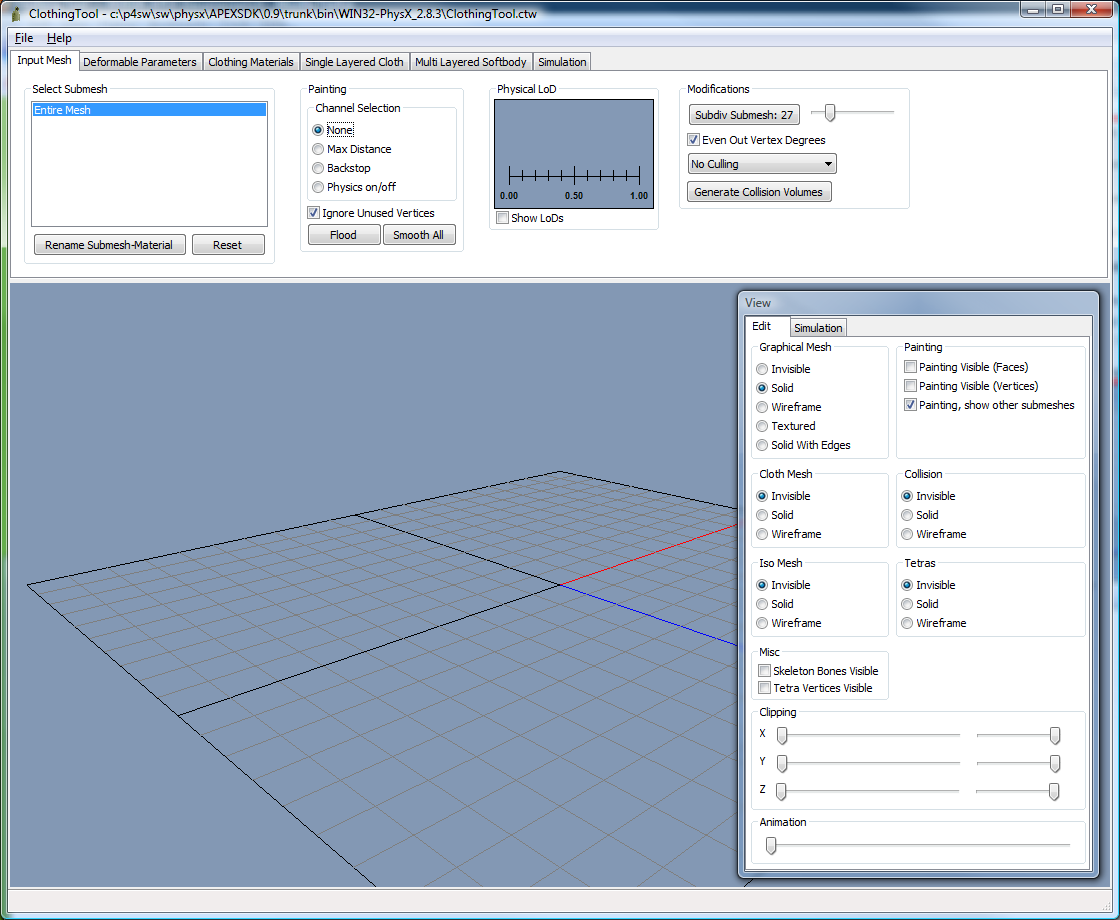
Run ClothingTool.exe. You should see this application
There are 6 different tabs in the main window:
| Tab | Description |
|---|---|
| Input Mesh | Allows the user to load a graphics mesh and author the different sub meshes to enable PhysX clothing simulations. |
| Deformable Parameters | Provides the user control over PhysX clothing settings. |
| Single Layered Cloth | Allows the user to create and run PhysX clothing simulations as well as store the APEX clothing asset files (.aca) |
| Multilayer Cloth | Experimental Tab for multilayer cloth |
| Multilayer Softbody | Experimental Tab for softbody simulation |
| Simulation | Controls the simulation window for clothing and softbody simulations. |
In addition there is the “View” window for different visualization effects
| Tab | Description |
|---|---|
| Edit | Enable/disable different visualizations for the graphics mesh, skeleton, cloth and softbodies. |
| Simulation | Enable/disable different visualizations for the graphics mesh and the physics mesh. |
Input Mesh
First an input mesh needs to be loaded. This is accomplished through the File/Open Workspace and File/Load Mesh menus. A workspace is a reference to a mesh with all the settings from the tool as it was last used.
There is support for a FBX and various export formats such as Ogre XML (.mesh.xml), EazyMesh (.ezm) and PSK (ActorX export).
Select Sub-mesh
The sub-mesh selection box allows the user to select the different authorable clothing sub-meshes. We recommend using different sub-meshes for different clothing areas to be simulated, e.g. a cape, hair, skirt, jacket, etc.
Each line corresponds to a meshname/materialname pair. Multiple ones may be selected to create one single Clothing Asset from.
Manipulating the View
Normal Viewing mode:
| Key Combination | Description |
|---|---|
| Left-mouse-drag | The model will rotate around the y-axis |
| Middle-mouse-drag | The model will translate in the x-z plane |
| Right-mouse-drag | The model will zoom closer or farther (z-axis) |
Painting mode:
| Key Combination | Description |
|---|---|
| Left-mouse-drag | Paint value specified in “Painting -> Paint Value” |
| Right-mouse-drag | Paint value of 0 (disabled). The blue color means that the graphics mesh will only move based on the animation and not based on any physics simulations. |
| Mouse wheel | Allow the user to change the radius of the painting brush |
| ALT-Left-mouse-drag | The model will rotate around the y-axis |
| ALT-Middle-mouse-drag | The model will translate in the x-z plane |
| ALT-Right-mouse-drag | The model will zoom closer or farther (z-axis) |
Simulation mode:
| Key Combination | Description |
|---|---|
| Left-mouse-drag | The model will rotate around the y-axis (only if no clothing is picked) |
| Left-mouse-drag | Allows the user to move the physical clothing mesh |
| Middle-mouse-drag | The model will translate in the x-z plane |
| Right-mouse-drag | The model will zoom closer or farther (z-axis) |
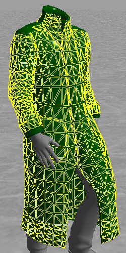
Paint Graphics Mesh
The paint tool allows the user to paint different clothing specific parameters on the graphical mesh. In order to enter to actually paint on the mesh the user has to select the painting mode from the Painting radio selection. As soon as the painting mode is active, the actual graphical wire-frame mesh will be visible and the mouse pointer will change to a circle.
There are currently three parameters:
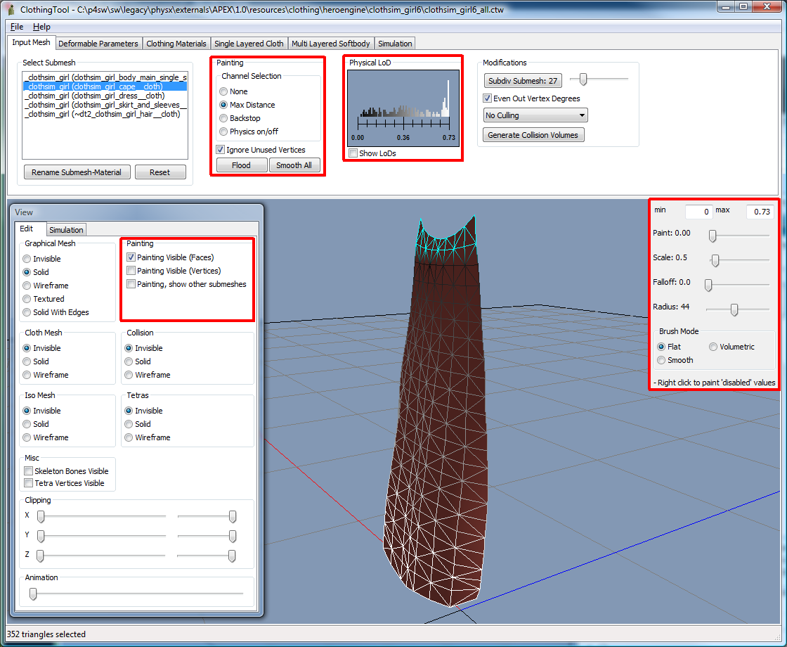
Max Distance
The maximum distance specifies how much a clothing particle can move from its animated position. The larger the maximum distance the more freedom the clothing particle has and the more it will move. The default value for the mesh is ‘blue’, which means all vertices will be animated and not simulated. The user can paint a value by specifying it in the ‘Paint Value’ Selector and painting the value by clicking on the left mouse button. Pressing the right mouse button will remove the painted value.
The clothing part which is attached to a rigid body should be painted disabled (blue) with the right mouse button. The ‘Smooth All’ button will never change the disabled values, but will change everything else to allow a gradual transition between different max distance values. The distance itself can be visualized by enabling the ‘Painting Visible (Vertices)’ in the ‘View::Edit’ window. The maximum distance can be quickly scaled up and down through the ‘Max Distance Scale’ slider.
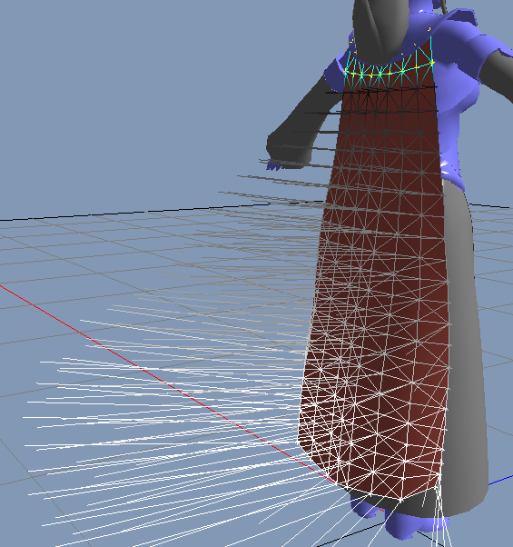
The distance is visualized as a line along the vertex normal, but in simulation the vertex is allowed to move inside a sphere with this radius around the cloth particle. Visualizing the ‘Painting Visible (Vertices)’, allows the user to visualize roughly where and by how much a clothing vertex can move.
The Paint slider will vary between the min and max value selected. Coloring of the vertices will be black for all distances smaller than min and white for all distances larger than max. Blue remains for disabled values.
- There is three brushes:
- Flat will only paint connected parts of the mesh from where the mouse pointer hits
- Volumetric will paint everything inside a sphere around the mouse pointer
- Smooth is a variation of Flat which will not paint the vertices but smooth them.
Falloff allows to select whether the paint value should be applied to all vertices inside the brush directly (falloff = 0), linearly descending with distance (falloff = 1), quadratically with distance (falloff = 2) or something in between. The shape of the brush will display this.
The Histogram in the main window displays the distribution of max distance values.
Note
For proper clothing animation results, always ensure that the clothing mesh is attached to the character with a motion distance of 0 (blue) with a subset of vertices. This means it is effectively skinned to the character and won’t fall just down.
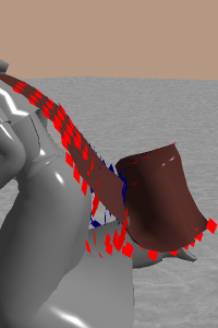
Backstop
- The Backstop is used for colliding the mesh with itself. It specifies how far a clothing particle can move based on the underlying animation. If neither Backstop nor Collision volumes are set for the character, the clothing mesh will only obey to gravity and ignore the shape of the character.
- This can be easily avoided by enabling Backstop. A value of 0 will ensure that the physical clothing mesh can only move towards the positive normal of the animation mesh and therefore avoid penetration. A bigger value will allow the clothing mesh to penetrate the animation mesh slightly based on the configured value. The penetration can be made visible through the ‘Painting Visible (Vertices)’ checkbox in the View window. A value below 0 will add additional thickness between the animation mesh and the actual physical clothing mesh. The Backstop distance from the animation can be scaled with the ‘Collision Distance Scale’ slider.
- Backstop is disabled for a vertex if the value is bigger than its Max Distance value.
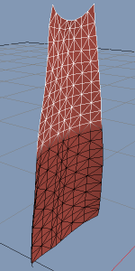
- The colors indicate the paint value. Black is disabled Backstop. White means collision distance is set to 0, aligning Backstop with the animation. Collision distance larger than zero goes from red to yellow, smaller than zero from blue to cyan.
Backstop painted to zero (upper part only)
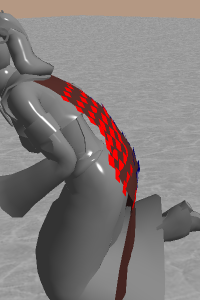
Backstop painted positive/inwards (lower part only)
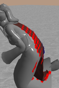
Backstop painted negative/outwards (lower part only)
 Reverse
Angle
Reverse
Angle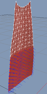
 Reverse
Angle
Reverse
Angle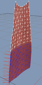
 Reverse
Angle
Reverse
AnglePhysics On/Off
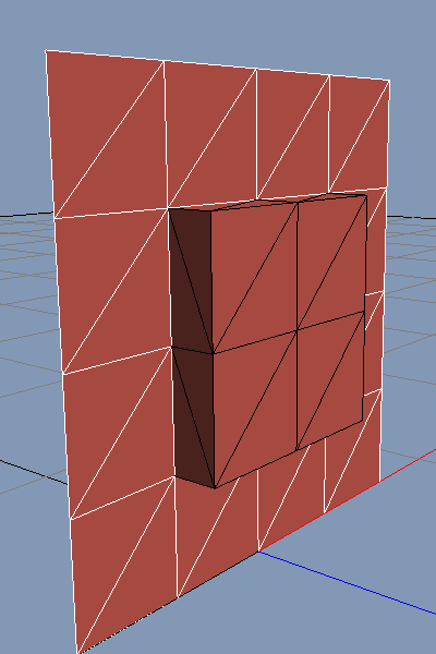
- This painting mode can be used to disable physics simulation from part of the mesh. Only two values are possible, either 0, which means Physics is disabled or 1, which means Physics is enabled. By default the physics simulation is enabled.
- This must not be confused with setting the max distance to 0. On/Off painting will remove vertices from the actual physical mesh and will skin them to the closest remaining simulated triangle.
- This is particularly useful for small of multilayer pieces in a single layered cloth as for example pockets. The inner layer is fully simulated, the outer layer is just skinned to that simulation. This prevents from unnecessary simulation overhead as well as from simulation artifacts.
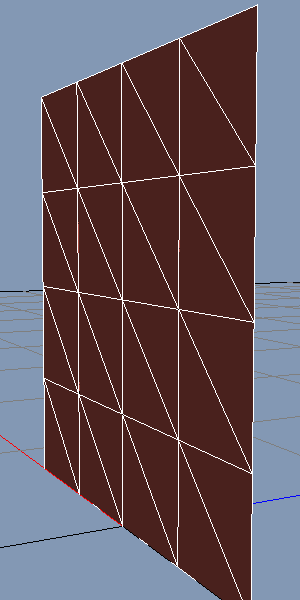
Sub-mesh Subdivision
The Clothing tool allows the user to subdivide a graphics mesh further through the ‘Modifications’ interface. Since the clothing physics mesh is generated based on the graphics mesh, subdividing the graphics mesh results in a higher tessellated physics mesh.
If the physics mesh tessellation is pretty high, it is recommended using the ‘Hard Stretch Limitation’ feature provided in the Clothing Material library
Culling
This is used to tell the tool and APEX how to cull a specific mesh. It applies for the entire mesh, and not just for a sub-mesh.
This information will be stored in the asset and given out through the Render API.
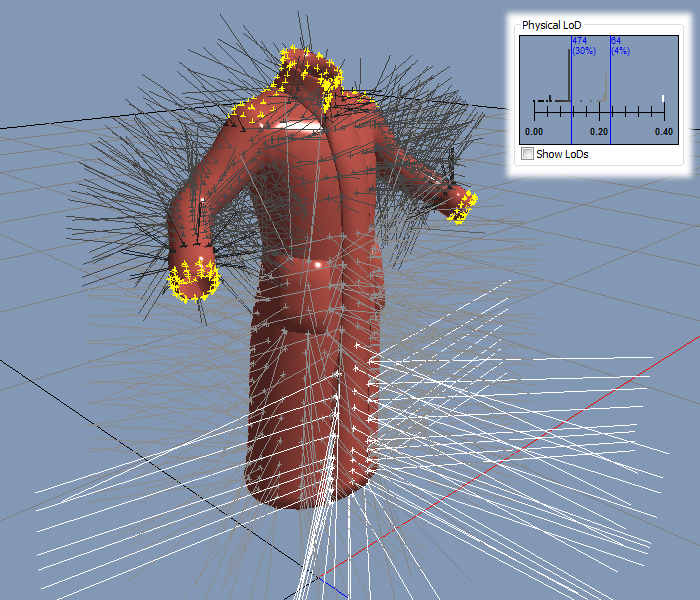
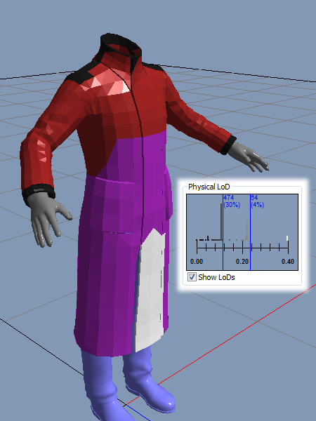
Histogram and multiple physics meshes
This will generate a multitude of physical meshes each a subset of all triangles. Additional meshes will have a smaller subset, containing only vertices of high max distance.
The additional physics meshes allow the APEX run time to switch between the different physics meshes when the allocated resources for clothing simulation are exceeded.
Each blue line in the Histogram will generate an additional physical mesh, based on the subset of vertices that have a max distance greater or equal to the blue line.
| Histogram and painted Max Distance values | Physical LoD visualization |
|---|---|
 |
 |
| Lod 1 | Lod 2 | Lod 3 |
|---|---|---|
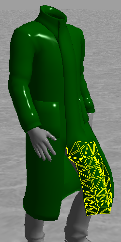 |
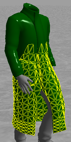 |
 |
Generate collision volumes
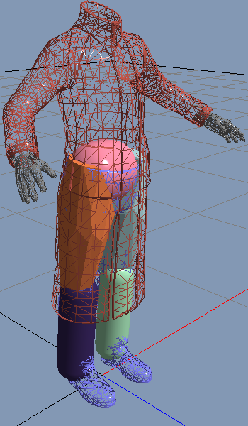
The tool provides the capability to automatically generate primitive and/or convex collision volumes based on the ragdoll mesh. Select ‘Generate Collision Volumes’ which will open a new window for Collision Volume Generation.
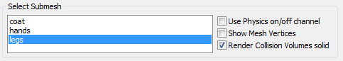
The collision volume generation window provides a sub-mesh selection as well as a bone skeleton hierarchy. Only sub-meshes selected here (rendered in blue) will contribute to collision volume generation. One or more collision volumes can be created for each bone.
Automatic Generation
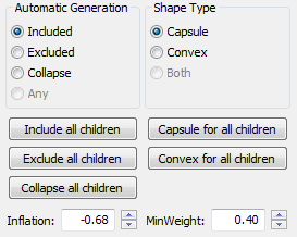
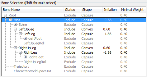
Each bone can have 3 different options for automatic geometry generation:
| Include | All vertices that this bone references to with more than <Minimal Weight> weight will contribute to the collision volume |
| Exclude | This bone will not generate a collision volume. |
| Collapse | All vertices that this bone references to with more than <Minimal Weight> weight will contribute to the parents collision volume. This works recursively: If the parent is also marked as ‘Collapse’ they will both collapse one more hierarchy level, until one parent is either marked as ‘Include’ or as ‘Exclude’. The later case will not create any collision geometry for all those bones. |
The default value for every bone is ‘Include’. However if the bone name contains either ‘finger’ or ‘toe’ the default will be ‘Exclude’.
Each bone can either have a Convex or a Capsule collision volume.
- The convex collision volume is generated by computing the convex hull from all the vertices gathered for a certain bone.
- The capsule collision volume is generated by computing the best fit capsule for the gathered points.
The <Minimal Weight> value can be changed per bone which will trigger an auto update for that particular bone.
If at any state the auto update seems to produce wrong results, the ‘Build Collision’ button can be pressed for full regeneration.
Inflation
After automatic generation, each collision volume can be inflated (or deflated). For capsules this will just modify the radius, for convexes it will move their vertices.
Manual generation
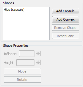
When selecting a single bone, the collision volumes can be altered or even fully regenerated for that bone. Additional volumes can be added, and they can be moved and rotated as well as changed in size.
Note
For performance reasons it is highly recommended to use Backstop instead of collision volumes wherever possible. Also convex collision is notably slower than capsule collision.
Deformable Parameters
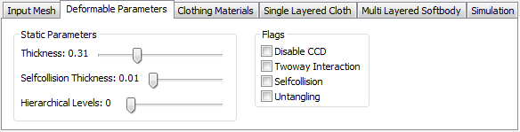
Static Parameters
Thickness
Each Cloth Vertex will be simulated as a sphere with half this thickness as the radius. This allows the cloth vertex to keep a minimum distance off from any collision volume.
Self-collision Thickness
When turning on self collision (see Flags section) each particle will be represented as a sphere. Colliding with other spheres will be more likely if they are bigger.
As usual the rule is. Keep them as small as possible, but as big as needed.
Hierarchical Levels
Number of hierarchical edges the Cloth will create. This is only applicable if the number of hierarchical solver iterations in the Clothing Material is set to larger than 0.
Note
Use with care. This will increase the cooking time significantly, use more memory and more CPU at run time. Hard Stretch Limitation might be a better alternative to try first.
Flags
Disable CCD
Never use Continuous Collision Detection. Setting this is not recommended. The ClothingActor will take care when to use and not use this flag upon teleportation or similar situations where continuous collision is not desired.
Two-way Interaction
Enables two-way coupling of clothing and dynamic rigid bodies. This is usually not necessary since regular clothing has very limited influence on most dynamic objects.
Self-collision
Turn on self collision. See also Self Collision Thickness.
Note
This comes with some severe performance implications!
Untangling
If self-collision could not prevent the cloth from entangling with itself
Note
This comes with big performance implications, use with absolute care!
Clothing Material
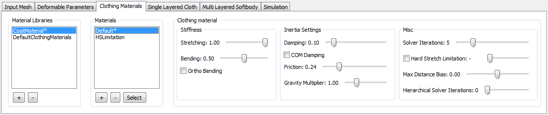
Material Libraries
This list box presents the list of all currently loaded clothing materials. Select one to display its list of materials in the next window.
Using the [+] and [-] buttons more material libraries can be added or released.
Materials
Display the list of Materials inside a Material Library. Select one to watch all the settings.
Using [+] and [-] buttons more materials can be added to or removed from the library. The [Select] button will select the current combination of library and material for the next clothing asset that is created.
Clothing material
A series of elements presenting all the contents of a clothing material
Stiffness
Stretching
The amount of stretching an edge can compensate. This can be in the range (0.0, 1.0]
Note
If full stretching is not enough, use the Hard Stretch Limitation
Bending
The amount of bending an edge can compensate. This can be in the range of [0.0, 1.0]
Ortho Bending
Using a mathematically more correct version of bending. Comes at some performance cost and rarely with a gain in quality.
Inertia Settings
Damping
Amount of constraint damping. This does not damp absolute velocity, only oscillations in edges.
COM Damping
Damping relative to the Center Of Mass of the mesh. Behaves a bit like a metal plate, but does not work very well on characters.
Friction
The amount of velocity that is removed when sliding over a surface.
Gravity Multiplier
Affects the amount of gravity a cloth gets applied to. 0 means no gravity at all, 1 means regular gravity, larger than 1 means more than regular gravity.
Note
By setting this to some value between 0 and 1 the cloth will behave more similar to fabrics that are very light and have a high air resistance.
Misc
Solver Iterations
Directly mapped to Cloth solver iterations. Higher number can reduce some stretching, but scales very linear with performance. A value of 5 is a good start, but if it also works with lower version, performance will be better.
Hard Stretch Limitation
The amount of stretching that is permitted. 1 means no stretching is allowed at all. 1.1 means each edge can be extended up to 1.1 times its original length before this kicks in.
Note
Only a subset of all edges can be treated with hard stretch limitation. This can be visualized using the debug rendering flag.
Max Distance Bias
Deforming the max distance sphere
- [-1.0, 0) sphere is shrunk into a capsule until at -1 becomes the normal
- (0, 1.0] sphere is shrunk into a disc until at 1 becomes a flat circle in the tangential plane.
Hierarchical Solver Iterations
Amount of iterations done on the hierarchical mesh. This is a workaround for fixing high stretching. Must not be used in conjunction with the hard stretch limitation.
Single Layered Clothing
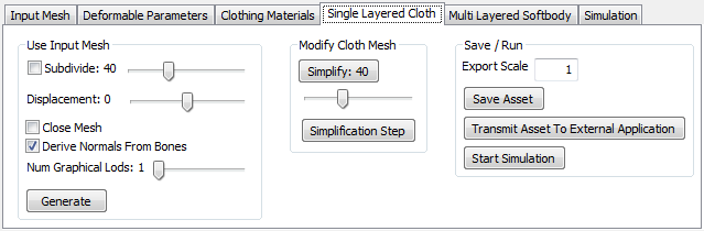
After the graphics mesh was edited, a physical clothing mesh can be generated by clicking on ‘Create’ in the ‘Use Input Mesh’ group. This will generate a green mesh, which is the physical clothing mesh.
The user can change the physical mesh and generate a higher resolution physics mesh through the subdivide feature or simplify the physical mesh through the ‘Modify Cloth Mesh’ group. If there are no changes to the physical clothing mesh, the physical simulation mesh and the graphical mesh are identical (immediate clothing). As soon as the user changes the physical mesh in the ‘Single Layered Cloth’ tab, the graphical and the physical mesh are differing and therefore a more complicated algorithm has to be used to skin the graphical mesh to the physical mesh.
The actual clothing simulation can be started with the ‘Start Simulation’ button in the ‘Save/Run’ group. There the Clothing Asset can also be stored as either a .aca file (using legacy serialization) or any of the module agnostic serialization formats (.xml, .ini or .abi).
Use Input Mesh
Subdivide
Subdivide the clothing mesh right after import from the graphical mesh.
Only needed when the graphical mesh has ill-shaped triangles or is tessellated very irregularly.
Close Mesh
If the graphical mesh has holes, they will be closed in the physical mesh.
Displacement
Move each physical vertex along its normal.
Derive Normals from bones
Instead of copying normals from the graphical mesh, the bone hierarchy is consulted and the normal is pointing away from the bones.
Generate
Will actually create the clothing physical mesh according to these parameters.
Modify Cloth Mesh
Simplify
Simplifies the clothing mesh up to a certain edge length.
Simplification Step
Removes around 10% of the edges with each subsequent click.
Save/Run
Save Asset
Writes the clothing asset into a stream (either .aca or .xml/.ini/.abi files).
Transmit to External Application
Some Game Engines such as Unreal Engine 3 support direct transmission to the Editor instead of going through the file system.
Start Simulation
Generate one or more actors from the clothing asset and simulate it.
Multilayer Clothing
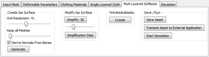
Generating Multilayer Clothing is similar to Single Layered Clothing, though it takes a few more steps.
Step 1) Create an Iso Surface
The Grid Resolution
The bounding box of the mesh will be filled with grid cells. The edge length of such a grid cell is the bounding box diagonal divided by the <Grid Resolution>
Keep all/some meshes
There can be multiple disjointed iso meshes. The most frequent case is the inner and outer mesh, usually when the original mesh is closed. This allows to select how many meshes to keep. The meshes with a higher vertex count will be kept longest.
Derive Normals From Bones
Instead of using the mesh normals from import, normals are computed as the direction pointing away from the bone with the largest weight.
Create
Actually create the iso surface according to the parameters.
Step 2) Simplify the Iso Surface
Simplify <Number>
Simplify all edges that are shorter than the bounding box diagonal divided by the selected <Number>
Simplify Step
Each time this button is pressed it will simplify roughly 10% of all the edges.
Step 3) Tetrahedralize
This will fill the iso meshes with tetrahedrons.
Step 4) Start Simulation
- Alternatively the Asset can be saved or transmitted, identical as for Single Layered Clothing.
Simulation
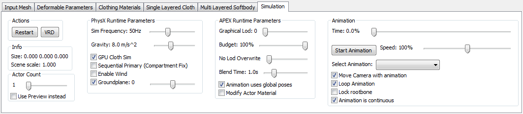
Actions
Restart
Restarts the simulation, all ClothingActors are released and recreated immediately.
PVD
Initiates a PVD connection
Info
Size
The size of the bounding box
Scene scale
Reference scale which scales most scene parameters such as Gravity, painting, debug rendering etc.
Actor Count
The slider allows to create up to 25 ClothingActors that will be independently simulated. Animation will be synchronous.
Use Preview Instead
Creates ClothingPreview classes instead of ClothingActors. This will allow only to animate the Clothing Asset, but not to simulate. Good comparison to what it would look like without clothing.
PhysX run time Parameters
Sim Frequency
Quickly change the Simulation Delta (which is 1 / simFrequency). Use with care, 50Hz and above are recommended. It is not very useful below 30Hz.
Gravity
Quickly play with various gravity values. The range is from 0.1 * ‘Scene Scale’ to 2 * ‘Scene Scale’
GPU Cloth Sim
Run the Cloth simulation on the GPU (CUDA capable GPU is required). Should not affect behavior, but performance will differ.
Sequential Primary (Compartment Fix)
Allows to run the Clothing Compartment before the Rigid Body Compartment. Can lead to more stable simulation, but doesn’t make a difference in most cases.
Enable Wind
Show/Hide Wind window
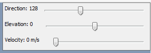
Direction
Rotate wind origin around the up axis
Elevation
Blow from above or below
Velocity
Modify strength of the wind
Groundplane
Moves the ground plane up and down
APEX run time Parameters
Graphical Lod
If available, select which graphical LoD is taken
Budget
Reduce the available simulation units. Useful to see how load balancing will work on multiple Actors.
Lod Overwrite
Force select which physical LoD is used.
Blend Time
Modify the Time it takes to blend from maximum physical LoD to no simulation at all.
Animation uses global poses
If Bind Poses are not identical in the Clothing Asset and the FBX file providing the animation, this is a workaround.
Modify Actor Material
Pop up a window that allows to modify the current material, or to set a new one per ClothingActor.
A ClothingActor needs to be selected by clicking it.
Animation
Time
The length of the animation
Start/Stop Animation
Speed
Select how fast the Animation is played back
Select Animation
Usually this offers to chose between the Bind Pose or the animation
Move Camera with animation
Lock the camera motion to the root bone motion.
Loop Animation
Jump back to 0 at the end of the animation and keep playing
Lock root bone
Overwrite the root bone translation to Zero all the time
Animation is continuous
Do set the isContinuous flag even when the animation loops back to zero
Visualization
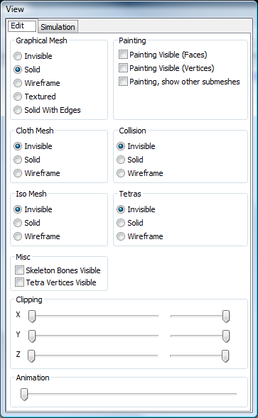
Graphical Mesh
Render graphical mesh textured, solid, wireframe or not at all
Painting
Painting Visible (Faces)
Render the painting on the edges of the mesh
Painting Visible (Vertices)
Draw Lines along the normal of each vertex displaying the paint value
Painting, show other sub-meshes
Display all sub-meshes that are not selected for clothing
Cloth Mesh
Draw the Cloth mesh solid, wireframe or not at all.
Collision
Draw collision volumes solid, wireframe or not at all.
Iso Mesh
Draw Iso Mesh solid, wireframe or not at all.
Tetras
Draw Tetra Meshes solid, wireframe or not at all.
Misc
Render the Skeleton as presented by the imported mesh
Clipping
Clip some of the intermediate meshes.
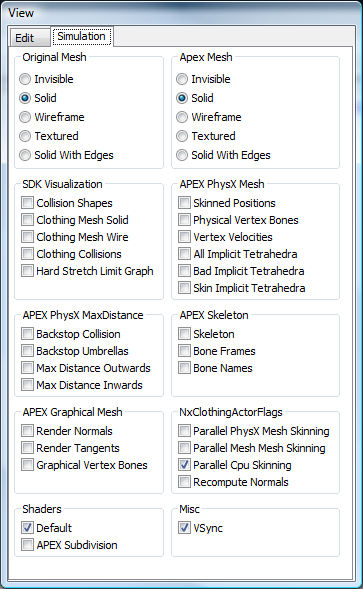
Original Mesh
Render the imported mesh textured, solid, wireframe or not at all
Apex Mesh
Render the simulated mesh textured, solid, wireframe or not at all
SDK Visualization
Collision Shapes
Wireframe render collision volumes from PhysX
Clothing Mesh Solid:
Render Simulation Mesh solid
Clothing Mesh Wire
Render Simulation Mesh wireframe
Clothing Collisions
Blue arrows for each Cloth vertex that collides with collision volumes.
Hard Stretch Limit Graph
Orange lines showing which edges have hard stretch limitation
APEX PhysX Mesh
Skinned Positions
Skinned positions of the physical mesh according to animation
Physical Vertex Bones
Shows the mapping between physical mesh vertices and the bones they skin to. White means a bone weight of 1.0, black a bone weight of 0.0
Vertex Velocities
Blue lines visualizing vertex velocities on the simulated mesh
All Implicit Tetrahedrons
Draws all implicit tetrahedrons for the entire physical mesh
Bad Implicit Tetrahedrons
Draws all tetrahedrons that have a graphical vertex mapped to them with barycentric coordinates outside the tetrahedrons.
Skin Implicit Tetrahedrons
Draws all tetrahedrons that are being used by the current mix of Mesh-Mesh Skinning and immediate skinning
APEX PhysX Max Distance
Backstop Collision
Visualize a subset of the simulation mesh where Backstop collision will occur. Red is outside, blue is inside.
Backstop Umbrellas
Visualize a small segment of the Backstop sphere at the current vertex location.
Max Distance Outwards
Display a line along the vertex normal that represents the radius of the Max Distance sphere.
Max Distance Inwards
Display a line along the negative vertex normal that represents the radius of the Max Distance sphere.
APEX Skeleton
Skeleton
Draw the subset of skeleton bones that are active in this APEX Asset (active bones are referenced by any of the meshes or have a collision volume)
Bone Frames
Draw the bone axis for each active bone
Bone Names
Draw the bone names for each active bone
APEX Graphical Mesh
Render Normals
Draw blue lines for each vertex displaying its computed normal.
Render Tangents
Draw red and green lines for each vertex displaying its computed tangent and bi-normal/bi-tangent.
Graphical Vertex Bones
The mapping from graphical vertices to bones. white line indicate a weight of 1, black lines a weight of 0.
ClothingActorFlags
Parallel PhysX Mesh Skinning
Skinning of the physics mesh will be done during simulation instead of before.
Note
This will cause one frame delay.
Parallel Mesh Mesh Skinning
Skinning of the graphical mesh according to simulation is done during the next time step.
Note
This will cause one frame delay.
Parallel CPU Skinning
All vertices with Max Distance 0.0 will be skinned regularly. This can and should be done during simulation already, so it should always be on.
Recompute Normals
Fully recompute the normals after all types of skinning have been done. This will replace the normals that were partly approximated or skinned with freshly computed ones. Some overhead but more quality.
Shaders
Default
Use a shader with per-pixel lighting.
APEX Subdivision
[experimental] Subidive the output mesh. A geometry shader will subdivide each triangle into 4 triangles and compute normals for the 3 new vertices. This can remove some artifacts with lighting, but also add new artifacts.
Misc
Vsync
Wait for screen refresh