Module Documentation
Introduction
The APEX Clothing Module provides an easy way to do real time character clothing. An animated mesh can be transformed into a simulated piece of cloth. Without much artist’s effort it flutters in the wind, produces wrinkles and physically interacts with the animated character and its environment.
The clothing module consists of a run time component and an authoring pipeline to create clothing assets. The run time component simulates a physics mesh, skins a graphics mesh to it and provides a flexible interface for rendering. It also includes an LoD mechanism to enable adaptive scaling of the computation effort depending on both platform and current scene setup. The authoring pipeline consists of an API to create and author assets in a custom tool. Ready to use tools are provided that implement this authoring API. Such tools are the plug-in to Autodesk Max and Maya and a standalone ClothingTool.
Animation and Simulation
Clothing is an essential part of a realistic and believable game character. Animating every little detail of the complex motion of a garment is nearly impossible. Also animation is not flexible enough to cope with physically simulated environments, for example in combination with a character ragdoll. The answer to that is the physical simulation of the cloth itself. However, just wrapping a simulated cloth mesh around an animated character does not lead to good results. The reason is that clothes are usually quite strongly constrained to the body that is wearing them. Normal cloth simulation in combination with collision volumes will not create these kinds of constraints. The Hybrid Clothing approach used in the APEX Clothing Module combines animation and simulation techniques to overcome these problems.
Hybrid Clothing
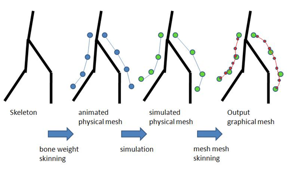
APEX Clothing gives an artist complete control over the animation of his character and at the same time takes the burden of animating the complex details of cloth motion. The idea is to take an animated character and add the simulation on top. The starting point to Hybrid Clothing involves just the normal components to character animation:
- An animated character skeleton
- A rendered graphics mesh that is skinned to the skeleton
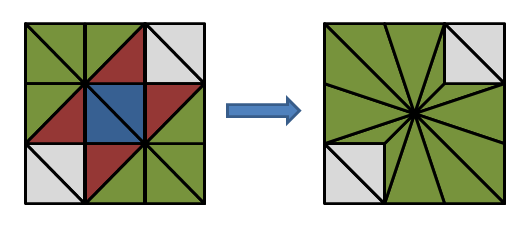
Tools are provided to create a physics meshes from the given graphics mesh. The part of the character that is chosen to be simulated cloth is not directly skinned to the animation skeleton anymore. Instead a few steps are performed to constrain the physics mesh to the animation (see illustration below). The created physics mesh is skinned to the animated skeleton. This provides the region within each vertex of the simulated cloth is allowed to move. After simulation the graphics mesh is transformed with the simulated physics mesh. This step is called mesh-mesh skinning.
Cloth Simulation
As mentioned above the simulated vertices are constrained to a region around their skinned positions. The artist can define how much each vertex is allowed to move by painting the maximal allowed distances (Max Distance) onto the mesh. An additional collision sphere can be defined by the artist to further reduce the freedom of the simulated vertex (see section Backstop).
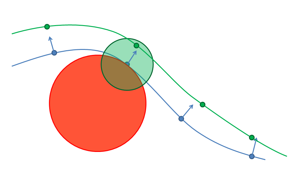
Blue points on line: physics mesh after skinning
Green points on line: physics mesh after simulation
Transparent circle: Max Distance sphere within which the vertex is allowed to move
Red circle: Backstop sphere
Run Time
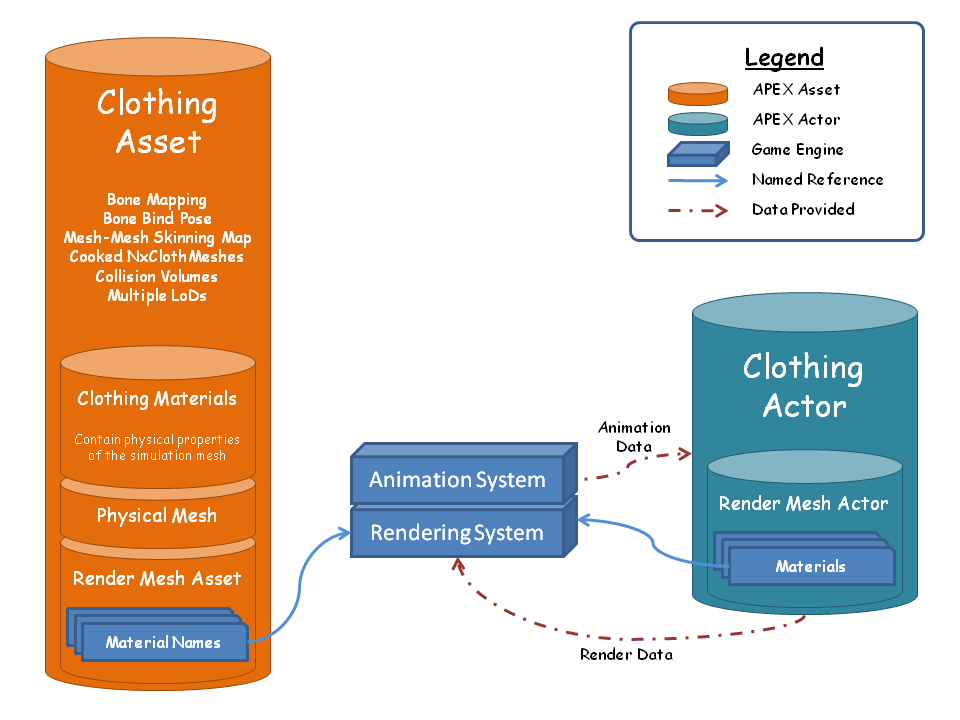
The ClothingAsset contains all the data coming from the authoring pipeline. It holds the information about bones, the physical mesh(es), the graphical mesh(es), the mapping between the two, the mapping between multiple physical meshes and Clothing material parameters.
The ClothingActor is an instance of the ClothingAsset. It is placed into a scene where it is simulated and rendered. The actor state is updated with the character animation that is provided with the current bone transformations. This will update the skinned positions of the physical mesh as well as the collision volumes that clothing will collide with.
Time stepping
For clothing to behave correctly, the timing has to be treated with some care:
When using variable timesteps with differing simulation deltas, the cloth stretchiness can vary drastically. The strength of this effect depends on variance of the timestep sizes. This is very noticeable and highly undesired. When using the Hard Stretch Limitation this effect can be worked around to a certain degree, but in general it is advised to use fixed timesteps. (consult PhysX docs regarding PxScene::setTiming() or PxSceneDesc::timeStepMethod)
This also affects other Cloth features such as bending etc., but by far not as noticeable as the stretching.
When using fixed timesteps simulation deltas that are not the substep size this will lead to multiple substeps per simulation call. Multiple substeps can lead to some jittering in the clothing due to the fact that there is no new animation data for the second substep. The simulation now sees the animation in stop and go. One substep it’s different from the previous one, the next step is not. This makes it very difficult to have consistent vertex velocities.
To summarize, the best scenario is using fixed timesteps with a constant simulation delta. This is in fact identical to using variable timesteps with a constant simulation delta.
Adaptive Target Frequency
As a countermeasure to the first problem with variable timesteps, the Adaptive Target Frequency has been created. This feature adapts the per-cloth gravity slightly. In practice a single value is very hard to find or the difference between target frequency and simulation frequency can get quite large leading to unrealistic simulation artifacts.
As a solution, the target frequency is computed as the average over the real last N (normally 60) simulation steps. This will still allow the cloth to stretch more or less depending on the timestep size, but it will be much less noticeable.
Authoring

The above diagram shows the work-flow to create a clothing asset. The graphics mesh is represented in the RenderMeshAssetAuthoring class. It contains the vertex buffers needed for rendering and also takes the buffers that can be painted on the mesh and are needed later in the clothing module. The render mesh asset is the main input for all the authoring paths. It is stored as the mesh to be rendered in setMeshes. It also serves as input to the creation functions of the physics mesh. There are three different paths to create such a physics mesh:
Single Layered Mesh
The graphics mesh is simple enough to be directly used as a simulation mesh (immediate clothing) or the simulation mesh can be derived through simplification.
Multi Layered Mesh
The physical mesh is created from an intermediate ClothingIsoMesh. It can either create a triangle mesh (cloth) or a tetrahedral mesh (softbody) to be simulated. The iso-mesh provides the functionality of simplification and contraction to create the physical mesh from the iso-surface.
Custom Mesh
The user provides his own mesh directly.
See section ‘Clothing Types’ for more details about the different paths.
Several graphics meshes can be provided for different graphical LoD levels. For each graphical LoD a different physical mesh can be provided. This enables better immediate clothing for each graphical LoD. It is also possible to use the same physical mesh for different graphical LoDs.
Painting Channels
The painting channels contain values that have to be painted by an artist onto the graphics mesh. The values will be interpolated to the physics mesh when the mapping between the meshes is created in the ClothingAssetAuthoring class.
Max Distance
The Max Distance channel defines for each simulated vertex how far it is allowed to move away from its skinned position.
Collision Radius
Collision radius > 0 turns on Backstop for a vertex. The radius defines the size of the collision sphere. See section ‘Backstop’ for more details.
Collision Distance
The collision distance will move the collision sphere inwards, I.E. against the mesh normal. This only has an effect if the collision radius for that vertex is > 0 and a collision sphere exists. If the collision distance is zero the collision sphere exactly touches the skinned position. This means the simulated vertex will collide against the skinned position. Negative values will move the collision sphere outwards. See section ‘Backstop’ for more details.
Master / Slave (Latch-To-Nearest)
Master and Slave are two separate painting channels containing a 32-bit mask. The information of these two arrays belongs together but contains two pieces of information.
- The slave mask per vertex contains the information whether a vertex is allowed to be simulated. Any vertex with an active slave mask will be excluded from the simulation mesh.
- The master mask contains the information which slave vertices may be attached to a particular triangle. Only if the master and slave masks overlap the mesh-to-mesh skinning attachment will be generated.
This is a generalization of the on/off painting channel in Apex 1.0. The first information was already contained in the boolean channel, but sometimes the slave vertices would attach to the wrong part of the mesh, usually in places of complex geometry. The master/slave combination allows to express which slave vertices can attach to which master vertices, giving full control to the artist working on these meshes. At the same time it will not be necessary to use it if the vertex-to-triangle attachment is already correct - therefore not increasing the work for clothing that do not suffer from this problem.
Clothing Types
There are several different approaches to put a simulated cloth onto an animated character. The approach that has to be chosen depends on the type and resolution of the graphics mesh that is supposed to be simulated. This chapter explains the different possibilities and explains when to use which approach.
Immediate Clothing
Directly Simulate the Graphics Mesh
Immediate Clothing is the simplest approach to character clothing. The physics mesh is directly created from the graphics mesh. The two meshes match up exactly and no expensive skinning is needed. However this means that either the rendered graphics mesh has to have a relatively low resolution or the physics simulation becomes very expensive. Also the garment should consist of a single layer, as cloth self-collision is too expensive to be used in real time.
Skinned Clothing
The physically simulated mesh does not need to be identical to the originally animated graphics mesh of the character. Instead a simpler physics mesh can be simulated and drive the more detailed rendered graphics mesh. This graphics mesh is updated by a ‘Mesh-Mesh Skinning’ step where the higher resolution graphics mesh is skinned to the lower resolution physics mesh after simulation.
There are different ways to create a lower resolution simulation mesh from the graphics mesh. Either the simulation mesh is derived directly from the graphics mesh, or an intermediate iso-surface is created to handle more complicated cases.
Simplify Graphics Mesh
The following algorithms are provided to derive a lower resolution physics mesh from a graphics mesh:
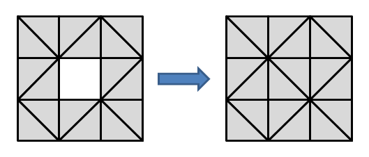
Welding
Graphical meshes often have duplicated vertices for texture rendering. This is not suitable for a physically simulated mesh where the mesh topology is essential. In a welding step all graphics vertices that are at the same position are merged into one single simulation vertex.
Simplification
A high resolution graphical mesh can be reduced to a lower resolution physical mesh by removing edges.
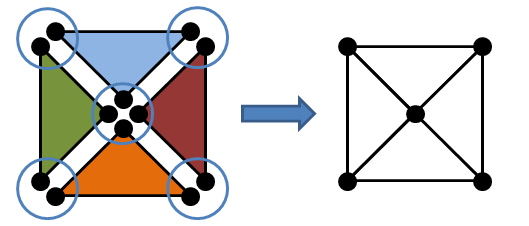
Vertex Selection
It is possible to select a subset of the graphical mesh to specify the physical mesh. This can be used to discard parts of a mesh that are not suited for simulation, such as sleeves or double layers of cloth that would cause self-collisions.
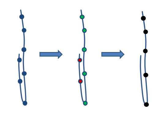
The blue line shows the graphics mesh with the blue points as its vertices. Green vertices are selected for simulation, red vertices are discarded. The black points in the last image represent the physics mesh vertices. The discarded vertices of the graphics mesh will move with the closest simulated vertices through mesh-mesh skinning.
Physical Mesh from Iso-Surface
Direct creation of a physics mesh from the graphics mesh does not lead to good simulation results when the garment of the character has a more complicated structure than just a single layer of cloth. It is necessary to simulate such structures with a single simulation layer. An intermediate Iso-Surface can be created around the given graphics mesh to automatically generate a suitable simulation mesh.
Softbody Mesh
From the Iso-Surface a tetrahedral mesh can be generated to use in a softbody simulation. At run time the graphics mesh is skinned to the simulated softbody through mesh-mesh skinning. This works well because the tetrahedral mesh fully encloses the graphics mesh. Therefore the position of each graphical vertex can be described with the barycentric coordinates of a simulated tetrahedron.
Cloth Mesh
Alternatively a cloth triangle mesh can be derived from the iso-surface by contracting it to the medial surface. The skinning of the graphics mesh to the physics mesh only works well when the graphics vertices are close to the physics mesh.
This approach is currently still an experimental feature.
Provide Custom Mesh
Instead of deriving the simulated mesh from the graphical mesh, an artist can provide a custom created simulation mesh to which the graphics mesh is skinned during simulation. This allows complete flexibility to get a well behaving simulation mesh. Of course the quality of the mesh-mesh skinning highly depends on how well the physics mesh fits the graphics mesh.
Examples
a) 
b) 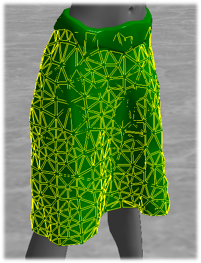
a) Immediate Clothing
b) Single Layered Clothing using Mesh-Mesh Skinning
a) 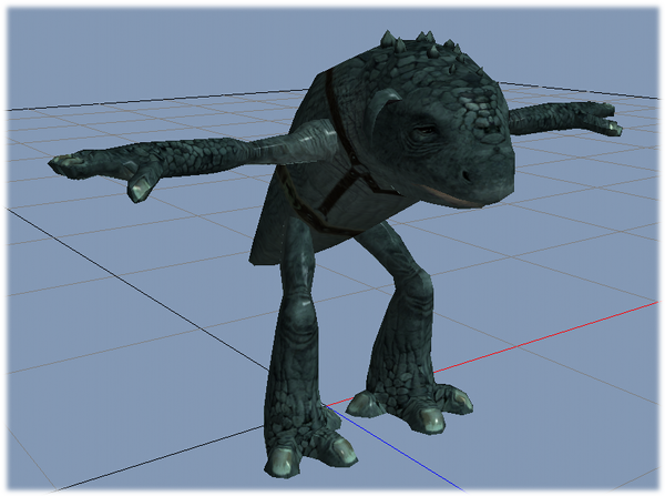
b) 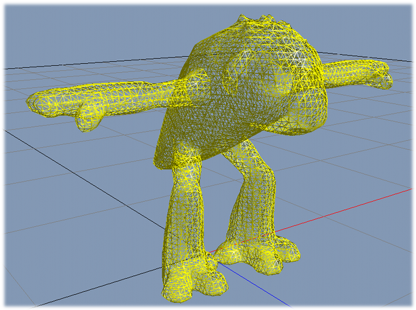
c) 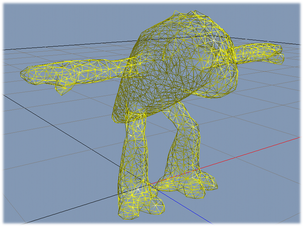
d) 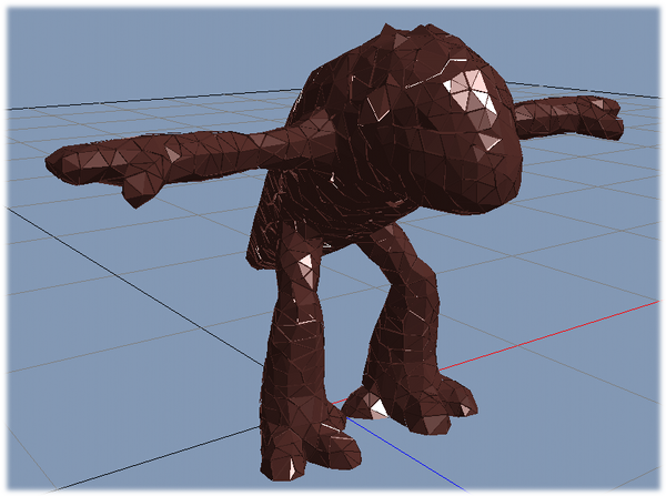
a) Graphics mesh
b) High resolution iso-surface
c) Simplified iso-surface
d) Tetrahedral simulation mesh for softbody
Features
Physical LoD
Adaptive Max Distance
The cost for simulating a cloth depends linearly on the number of simulated vertices. In order to reduce this number when an actor in a scene is far away and is there not so important, the ClothingActor can decrease the Max Distance of the simulated vertices. Triangles that consist of vertices that have all vertices with a Max Distance less or equal to zero do not need to be simulated anymore.
The effect of this mechanism is that by decreasing the level of detail, regions that are allowed to move the least are replaced by animation first. When the camera is close the actor, for example, it is shown in its full detail, but from far away only those parts are still simulated that can actually be distinguished from the normal animation.
The Max Distance are blended smoothly between different LoD levels. It is possible to define the velocity of the Max Distance adaptation.
Reducing Solver Iterations
The cost of a vertex increases linearly with its solver iteration count. A specified simulation budget limits the total simulation cost, I.E. the sum of the simulation mesh vertices multiplied by their solver iteration count.
The physical behavior of a physics mesh changes with different numbers of solver iterations. Reducing solver iterations increases the stretchiness of the cloth. To counter that, the ClothingActor reduces the Max Distance of the cloth vertices at the same time.
Physical LoD Algorithm
see also Updating Actor Benefit for LoD in the Programmers Guide for Details on how the benefit can be set.
Physical LoD is a way of giving Resources to individual Clothing Actors based on a maximal resource budget for the entire scene.
- Each APEX Scene has a resource budget that can be changed for machines and platforms with various capabilities.
- Each Clothing Actor will have a benefit.
- Resources are given to the Actors with with higher benefit.
- Some Clothing Actors with more than one Physical LoD provide a set of configurations that require different amounts of resources. Depending on the relative benefit of two actors the LoD system will chose to run both actors at lower Physical LoDs instead of turning on one completely and the other one off.
- Transitions between physical LoDs is smooth and governed by the blend time.
- A Clothing Actor with zero benefit will be turned off immediately to free the resources as quickly as possible.
A Clothing Actor that is not simulated comes at almost zero overhead, unless the fallback skinning is activated.
Graphical LoD
Usually there are different levels of detail for the meshes of a game character. The APEX clothing assets and actors are able to handle that case. At authoring time each graphical level of detail is provided to the asset together with a matching physical mesh.
It is possible to use the same physical mesh for all graphical levels of detail. This implies that only one graphical LoD can do immediate clothing, I.E. graphical and physical vertices match up exactly. If that approach is used one has to be careful to account for the mesh-mesh skinning effort needed for LoDs without immediate clothing.
Alternatively a physical mesh can be provided for each graphical mesh. This enables immediate skinning for each graphical LoD. The switch between different physical meshes happens seamlessly by interpolating the mesh states between the different LoDs.
At run time the game engine tells the clothing actor at which graphical LoD it wants the actor to be rendered. This gives full control to the game engine about how many triangles are rendered for a character at all times. The graphical LoD is specified in dispatchRenderResources of the actor. Because APEX needs to know which physical mesh to use when skinning the vertices, this has only an effect for the next render call, so there is a one frame delay for switching graphical LoDs.
Graphical LoD vs Physical LoD
There are two orthogonal concepts of LoD in the APEX Clothing Module. Graphical LoD is completely controlled by the game engine. It specifies which graphical mesh is supposed to be rendered and how the corresponding simulated physical mesh looks like.
In addition to that the Physical LoD coexists. It dynamically scales down Max Distance if necessary in order to reduce the size of the simulated mesh for the current graphical LoD. This is based on actor priorities and a per scene simulation budget provided by the game engine.
Rendering
The application renders the simulated part of the animated character by implementing the APEX render interface, while the rest of the character is completely handled by the application.
There are two states of the ClothingActor that need to be rendered:
- The actor is completely simulated. Vertices are provided at their global position, already skinned.
- The actor is completely animated. Vertices are provided at their bind pose and bone matrices are provided for GPU skinning.
Collision with the Character
Collision Volumes
As the ClothingActor creates an Cloth or an Softbody it just interacts with any other object in the same PhysX scene. To prevent the simulated clothing from penetrating with the rest of the animated character there needs to be a collision representation of the animated character.
Stored in the Asset
It is possible to store collision volumes directly in the Clothing Assets. Convexes and Capsules can be specified to create collision representation for a character. The Clothing Actor creates instances of those volumes in the physics scene and moves them automatically with the bone skeleton.
Controlled by the Game Engine
Any tool for ragdoll creation, such as the PhysX plug-ins for Autodesk Maya or 3D Studio Max, can be used to create that collision volumes. If the game engine creates those collision volumes, they need to be kept in sync with the animation.
A ragdoll however does not necessarily provide the right collision volumes for clothing collision. Most of the time, ragdoll collision volumes are notably larger than the shape of the ragdoll to prevent any penetration at all costs. This will not look very good for clothing if the cloth is expected to stay within a certain distance of the character.
Also most pieces of cloth only need collision on a reduced set of bones. Collision volumes are expensive and should be minimized in numbers as much as possible.
This can lead to several synchronization problems.
- Out of sync due to clothing frame delay. When certain optimization flags are set, additional and artificial frame delays are created. The collision volumes need to be updated with the correct frame delay too.
- It is very important to choose when to call setGlobalPose and moveGlobalPose on Actors. This is non-trivial and will introduce strange effects for certain cases.
All these issues are solved automatically by the Clothing Actor if the collision volumes are stored in the asset.
Simulation Cost
Collision of cloth against convex shapes is relatively time consuming. Therefore it is recommended to use capsules or Backstop (see chapter Backstop) whenever possible. If convexes are needed it is good to make them as simple as possible, as the simulation cost is proportional to the number of convex planes.
Backstop
Sometimes it is difficult to provide a rigid body collision representation for the animated character that fits well over the entire animation. In particular it needs to be very detailed at regions on the character where the cloth mesh is always close to the body, authored to just create small wrinkles. The APEX Clothing Module provides an alternative way to do efficient collision of the simulated mesh with the character.
The idea is to use a sphere under the skinned position of a physics mesh vertex to collide with. A simulated vertex is allowed to move inside a sphere with radius Max Distance that is centered at its skinned position (blue circle in the illustration below). The skinned vertex positions are animated according to the skeleton bones of the character. Backstop defines an additional sphere that further restricts the motion of the simulated vertex (red circle). Two parameters that can be painted for each vertex define Backstop: collision radius and collision distance. Collision radius > 0 enables Backstop for that vertex. It should be some value bigger than Max Distance to prevent the vertex from just passing by the Max Distance-sphere on the side. The collision distance allows moving the collision sphere up or down the mesh normal. Positive collision distance moves the sphere inwards against the normal, a negative value displaces it outwards along the normal. To prevent the (blue) motion area from becoming too small when moving the collision sphere outwards, the Max Distance sphere is also moved along the normal.
a) 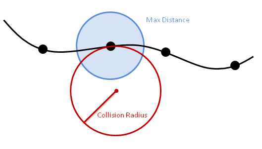
b) 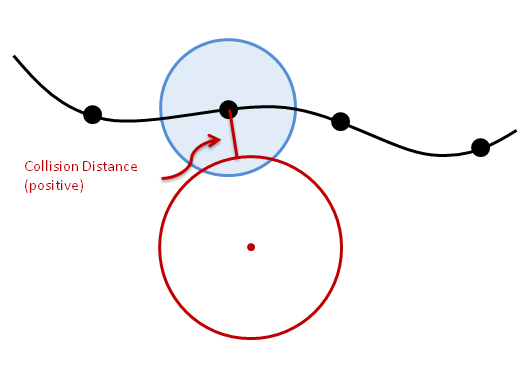
c) 
The images above show an example for one vertex of a physics mesh. The black dots are the vertices at their skinned position. The simulated vertex is allowed to move within the blue circle that shows the Max Distance. The red circle represents the collision sphere that is defined by collision radius and collision distance. The simulation can move the vertex within the blue region.
CollisionSphereDistance = 0:
Collision sphere touches the skinned position.
CollisionSphereDistance > 0:
Collision sphere is displaced inwards against the normal.
CollisionSpheredistance < 0:
Collision sphere and Max Distance sphere are displaced outwards along the normal.
Simulation Normals
Simulation Normals are the direction in which Backstop collision is applied. Max Distance Bias is also affected by the simulation normals. They are valid even for tetrahedral meshes since they are not generated from mesh topology.
Simulation Normals from Graphical Mesh
The normals of the physical mesh are taken from the closest graphical vertex where the physics on/off channel is painted to ‘on’. When having a multi-layered cloth the outer layer can be painted as ‘on’ such that all the normals of the physical mesh will point outwards.
Derive Simulation Normals from Bones
Alternatively there is an option to derive the normals from the bones. A physical vertex will derive the normal from the line between the closest point on the bone segments it is attached to the strongest. The bone segments are the lines that connect the bones to their children.
This option enables easy generation of normals that point outwards, even if the mesh is very complicated, like for hair for example. Normals that point outwards are essential if Backstop is used.
Rendering Normals
The normals generated for rendering vary on what skinning method is used to map the graphical vertex onto the physical mesh.
Immediate Skinning
The normal will be exactly the normal of the simulated mesh.
Note
When vertices were merged to form a connected simulation mesh, all the lighting features created through multiple normals per vertex will be gone unless the normals are fully recomputed.
Mesh-Mesh Skinning
The normal as well as the vertex positions get a barycentric coordinate within one of the implicit tetrahedrons. The normal will then be the normalized difference between the normal position and the vertex position.
Note
This can lead to some artifacts if the graphical mesh has a much higher resolution than the simulation mesh or the graphical mesh is spatially separated from the physical mesh.
Tetra Skinning
Similar to Mesh-Mesh Skinning, the normal is also stored as the position of the vertex plus the normal.
Recompute Normals at Run Time
When the result of the direct rendering normal generation is not good enough, normals can be fully recomputed after all the skinning took place. This can get rid of some artifacts, but at the same time will make any seam visible, even if a vertex gets split into two only because of texture coordinates.
Normals will be fully recomputed if the flag ClothingFlag::RECOMPUTE_NORMALS is set.
Tangent Space
If the RenderMesh that was sent to the Clothing Asset contains tangents and bi-tangents, the tangent space has to be updated. An algorithm has been implemented to do so, but if it doesn’t fit the needs a custom callback can be implemented to update the tangent space the way the game engine expects them.
Cloth Behavior
There are a different number of settings that influence the behavior of the cloth.
Gravity
Gravity accelerates the cloth vertices. Note that the gravity multiplier parameter changes the mass of the cloth and the vertices. If lowered it will to some degree generate a cloth that feels like a very light fabric with large air resistance.
Topology of the Simulated Cloth
The Resolution of the cloth has a big impact on the behavior. The Higher the resolution with a constant solver iteration count, the more stretchy a cloth becomes. The cloth solver needs to propagate forces further through the mesh. Also bending stiffness has a stronger impact when fewer triangles are simulated.
Solver Settings
There are different solver settings that impact the quality of the simulation result. With more solver iterations the result is closer to the initial state of the cloth. The behavior is therefore stiffer.
The hierarchical solver in the PhysX SDK helps to converge faster. The number of hierarchy levels and the number of hierarchical solver iteration can be specified additionally to the normal cloth solver iterations.
Hard Stretch Limitation
Even with the hierarchical solver the cloth still behaves a bit stretchy. In combination with clothing the PhysX SDK provides the Hard Stretch Limitation feature to create cloth that limits the stretching of the cloth completely by creating a projection tree starting at vertices that have Max Distance = 0.
Stiffness parameters
The parameters that control cloth stretchiness explicitly:
- Stretching Stiffness: Strength of the cloth distance constraint
- Bending Stiffness: Strength of the cloth bending constraint (angle between neighboring triangles)
- Hard Stretch Limitation Factor: Controls the threshold when Hard Stretch Limitation kicks in
Damping
Normal cloth damping reduces the relative velocities between the cloth vertices. This reduces oscillations and makes the simulation more stable. The look of the cloth becomes more ‘viscous’ the more damping is used.
Alternatively COM Damping can be used. This version damps the cloth vertex velocities relative to the frame of the center of mass. This makes the cloth behave more like a piece of metal sheet.
For most clothing pieces the COM Damping is of limited use.
Ortho Bending
If Ortho Bending is enabled the bending constraints are stronger, but the simulation is more expensive.
Collision Thickness
The thickness parameter is used for the collision of the cloth with rigid bodies.
Self-Collision Thickness
Self-Collision enables a collision test between all the vertices of the cloth. The vertices are represented by a sphere with radius of size thickness that is specified in the asset. A bigger thickness reduces the problem of self-entangling the cloth. However setting the thickness too high prevents the cloth from making small wrinkles.
Self collision comes with noticeable performance overhead.
2-Way Interaction
When the cloth is supposed to apply forces to rigid bodies, 2-way interaction has to be enabled. For example this is necessary if the cloth is supposed to slow down rigid bodies that hit the cloth, in order to make it look heavy.
If 2-way interaction is disabled the rigid bodies will just push away the cloth without being affected.
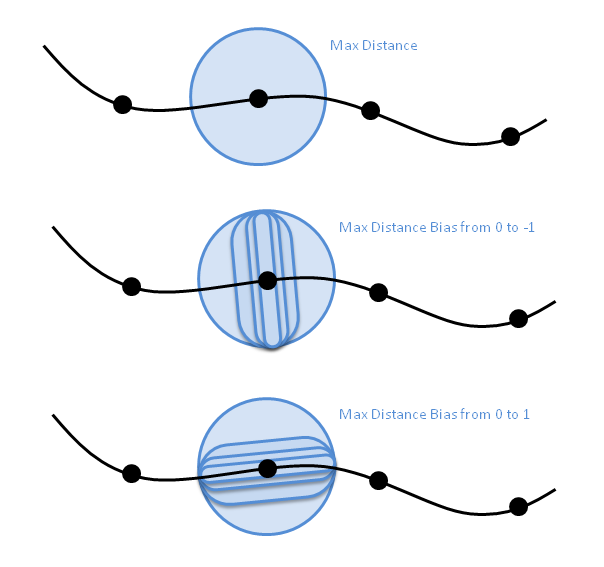
Max-Distance Bias
This will shrink the Max-Distance sphere. If the bias is negative the sphere will become a capsule until at a bias of -1 is reduced to the normal. If the bias is positive, the sphere is gradually reduced to a disc in the tangential plane.
Debug Visualization
The APEX Clothing Module provides different debug visualizations for the Clothing Actors.
Click here for a list of the Clothing debug visualization parameters
For general information on how to use debug visualization within APEX, please see Debug Visualization.
Skinned Positions
SkinnedPositions
Max Distance
MaxDistance
MaxDistanceInwards
Backstop
BackstopPrecise
Collision
CollisionShapes
CollisionShapesWire
Mesh-Mesh Skinning
Only one of these 3 flags will be rendered even if more of them are turned on. Top most will be favored.
SkinMapAll
SkinMapBad
SkinMapActual
Physical Mesh
PhysicsMeshWire
PhysicsMeshSolid
PhysicsMeshNormals
Bones/Animation
Skeleton
BoneFrames
BoneNames
Velocities
Velocities
Per Vertex Skinning Information
GraphicalVertexBones
PhysicalVertexBones
Serialization
The clothing module uses the generalized parameterized object from the APEX framework.
Parameterized Objects
The key concept is to give the user the freedom to create its own serialization classes. The Clothing Assets data can be accessed and then iterated.
A sample implementation is included with APEX and is implemented in the ClothingTool. This sample implementation can generate 2 different file types:
.apx
The xml file represents the entire hierarchy in xml tags. This is a verbose format, but great for debugging and very well human readable. File size is about 3 times bigger than binary.
.apb
Platform specific binary representation. For the matching platform this can even be deserialized in-place. ParamTool can convert between any .apx and .apb files and generate them for each platform.
APEX Streams
This method of serialization (.aca files) was deprecated in Apex 1.0 and is no longer available. Vital files of this format need to be converted to .apx/.apb using Apex 1.0 ParamTool. All versions of parameterized objects can be imported into the latest version of Apex.