
This chapter briefly covers the basics of all stereoscopic technologies then delves into the math behind the existing 3D conceptual pipeline. It extends the pipeline to encompass stereoscopic spaces and covers the basic operations 3D Vision Automatic performs on your behalf.
Delivering a compelling 3D image on a 2D screen has been the dream of content producers for nearly 160 years, beginning with anaglyph technology originally developed in the 1850s.
Although the technology has matured significantly, the basic concepts have remained largely the same.
Stereoscopic technology works by presenting each eye with a slightly different image, prepared as though the viewer was standing at a particular location. This can be done using many techniques.
Anaglyph, as already mentioned, was the first such technique. This is the traditional red/blue glasses with images that have been separated and desaturated. Originally developed in the 1850s, this technique saw fairly widespread adoption in Hollywood in the 1950s. This is also the technology used by 3D Vision Discover as a preview for what 3D Vision can deliver with a true shutter glass setup.
Polarization systems, as seen in some movie theaters, use multiple projectors with polarizing filters to display two images overlaid directly on top of one another. The viewer then wears passive glasses with matching polarized lenses—each eye gets one of the two images at exactly the same time.
Active systems, such as the shutter glasses sold by NVIDIA, use a set of lenses that alternatively become opaque and then transparent at a refresh rate that matches that of the user's display. By displaying only with monitors capable of using a native 120 Hz input signal, NVIDIA is able to deliver a smooth 60 Hz to each eye. This significantly reduces eyestrain over previous generations of shutter technology.
|
|
Note: To display stereo, Tegra powered devices requires: a 3D TV that supports 3D output from mobile devices; a 3D TV that supports HDMI 1.4 (or higher); or a stereoscopic panel display. |
There are two basic techniques to stereoized1Pseudo stereo effects or Stereoizers create a stereo signal from a source signal which is possibly (but not necessarily) a mono signal. content for games: active stereoization and passive stereoization.
In active stereoization, a game utilizes two different cameras to build and render distinct scenes to each eye. At the end of a single render update, the game engine tells the API which render target corresponds to which eye and moves on to building the next frame(s).
This poses significant challenges to developers that are developing in existing engines. One obvious obstacle is that many game engines rely on there being a single camera, while this technique requires two. In addition, the engine itself has to make decisions about which components of the scene are eye dependent and which components are not. Shadow maps are a common example of buffers that should be built only once. The engine additionally has to offer options to the user to manage the strength and complexity of the stereoscopic effect.
Active stereoization incurs runtime costs as well. For example, most titles already budget their draw call count to get the maximum fidelity possible while maintaining playable frame rates. Active stereoization will result in substantially more draw calls-up to twice as many—which can result in an application becoming severely CPU limited.
Finally, the effort to add support for active stereoization can range from a week or so to several months. The actual development time required is dependent upon the technology stack in question.
Passive stereoization attempts to mitigate these shortcomings and reduce development effort without compromising on the quality of the 3D effect. The application continues to render the 3D scene as normal. The 3D display driver watches as rendering calls go by and builds stereoscopic information from the calls made by the 3D rendering engine.
Using heuristics, the stereoscopic driver decides which objects need to be rendered per-eye and which do not, building the full left and right eye image in a manner that is transparent to the developer.
In effect, the stereoscopic driver does what an application developer would do, but it does so once for all titles. The result is a robust stereoscopic solution that requires significantly less effort from an application developer's standpoint.
Passive Stereoization, and specifically 3D Vision Automatic, is available for:
On its way through the pipeline, a primitive is transformed through many different coordinate systems, or spaces. Understanding issues with stereoscopic is greatly simplified with a solid understanding of the existing pipeline, and how stereoscopic modifies that pipeline. A reasonable facsimile of the spaces that a primitive travels through during display is shown in Figure 1.
Geometry is usually authored in model space. In this space, geometry is rooted at a local origin, which is commonly a location near the base of the model. This allows the model to be easily placed in the world as you might place a chess piece on the board.
To place models in the world, they will be transformed by the world transform. World space is application-defined, and serves as a useful mechanism for relating objects with each other.
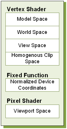
Figure 1. Spaces during Normal Render
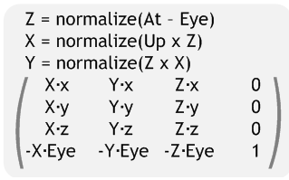
Once in world space, models are further transformed by the view transform, to relocate the model into eye space. Eye space has many names, among them view space and camera space. (For the purposes of this document, we will consistently refer to this as eye space to avoid confusion with viewport space). In a left-handed coordinate system, eye space has its origin at (0, 0, 0), X increasing to the right, Y increasing upwards and Z increasing into the screen. The canonical View matrix is as follows:
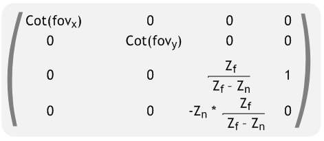
After eye space, the model is further transformed by the projection matrix to clip or projected space. This transform typically serves three purposes. First, it scales the X and Y position of the object by the appropriate aspect ratio of the display window. Second, it reinterprets eye-space Z from [Zn, Zf] to [0, Zeye] and stores this in the Z coordinate of the vertex. Finally, the projection matrix stores eye-space Z in the W coordinate of the vertex. A typical left-handed projection matrix is given below.
Note that while they are unique spaces, the model, view and projection matrix are often concatenated together to create the Model-View-Projection matrix. Vertices are transformed directly from model space to homogenous clip space.
Homogenous clip space is the last space developers typically think about, as it is the last space they can manipulate from the vertex shader. However, the trip through the conceptual pipeline is not complete. Next, vertices are clipped against a cube of size W. The vertex coordinates X, Y and Z are divided by W, and 1/W is placed in the W coordinate for later perusal. This step, referred to as the perspective divide, is performed in fixed function hardware. The resulting vertex is in normalized device coordinates.
Vertices are then grouped into primitives according to ordering or an index buffer, and are rasterized. The viewport transform is applied, creating fragments in viewport space. The pixel shader gets a chance to modify the output color, after which the final result is written to the render target for later usage or display to the user.
3D Vision Automatic modifies the existing conceptual pipeline by splitting the post clip space pipeline into left- and right-eye spaces. The stereoscopic conceptual pipeline is shown in Figure 2. The following sections cover how the existing conceptual pipeline is modified to create the stereoscopic pipeline.
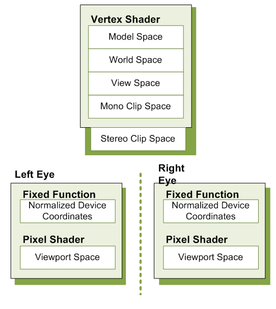
Figure 2. Spaces During Stereoscopic Render
Conceptually, the 3D Vision Automatic can be thought of doing two tasks: duplication and modification. As can be seen in the stereoscopic pipeline in Figure 1 2, viewport space has been split into a left- and right-eye viewport space. To support this, the driver does several things on the application's behalf:
One of the most obvious tasks that 3D Vision Automatic performs on an application's behalf is to duplicate the primary render target used. This allows the driver to build a render target to present each eye individually. Additionally, other render targets may be duplicated based on heuristic analysis at creation time. The driver handles all of the mapping for the developer, so that when the developer asks to bind a target, the appropriate per-eye target is bound. Likewise, if the developer uses render-to-texture, stereoization may be performed. If bound for reading, the proper left or right variant of the texture will be used.
While render target replication is necessary for correct stereoscopic display, it is not sufficient. 3D Vision Automatic also monitors vertex shader creation, and adds a footer to each shader. By using a footer, the driver is able to operate in clip space, which has several unique properties. Among them is that clip space is oriented the same way for all applications, regardless of local concerns. It is also unit-less. Because it is directly before the perspective divide, clip space has the unique property that scaling the x, y, z and w coordinates of a vertex by a scalar factor affects the apparent stereoscopic depth without altering the rasterized location or z-buffer depth of the resultant fragments. Given that the shader has placed the position result in a variable called PsInput, the equation for the footer looks as follows:
PsInput.x += Separation*(〖PsInput〗_w-Convergence)
Convergence is set to a relatively low value by default, and can be modified by users as described in Separation Adjustment on page 32. Values less than the convergence value will experience negative separation, and appear to the user as out of screen effects. When PsInputw is equal to Convergence, no separation is present. This is ideal for many HUD elements. Finally, objects further than Convergence depth will experience normal parallax effects. The effect becomes more pronounced the further the object is located from the Convergence plane.
|
|
Note: On the PC, Current Convergence values can be read using the function call NvAPI_Stereo_GetConvergence, and set with NvAPI_StereoSetConvergence.
|
Separation is more easily controlled using one of the methods listed in Separation Adjustment. Users will adjust the magnitude or Separation, while the current eye being rendered (left or right) will modify the sign of separation—positive for the left eye and negative for the right eye.
|
|
Note: Current Separation can be computed as the result of multiplying the results from calls to NvAPI_Stereo_GetSeparation and NvAPI_Stereo_GetEyeSeparation, and dividing by 100.
|
Neither Separation nor Convergence should ever be set to negative values.
Figure 3 shows separation and convergence as they conceptually apply to stereo.
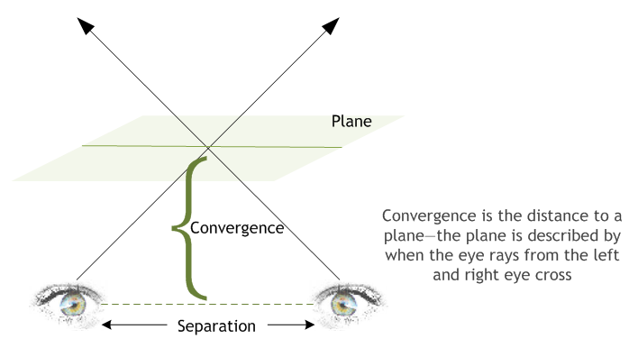
Figure 3. Separation and Convergence
When running in 3D Vision Automatic mode, application issued draw calls are substituted for two separate draw calls—one for the left eye and one for the right eye. The following pseudo-code could be thought of executing:
HRESULT NVDisplayDriver::draw()
{
if (StereoActive) {
VShader = GetStereoShader(curShader);
VShaderConstants["Separation"] = curSeparation;
VShaderConstants["Convergence"] = curConvergence;
SetBackBuffer(GetStereoBuffer(curBackBuffer, LEFT_EYE));
reallyDraw();

VShaderConstants["Separation"] = -VShaderConstants["Separation"];
SetBackBuffer(GetStereoBuffer(curBackBuffer, RIGHT_EYE));
reallyDraw();
  } else {
    // Normal draw call stuff
reallyDraw();
  }
}
Although this code is naturally a gross simplification, it is conceptually accurate.
NVIDIA creates a stereoscopic profile for each and every title that goes through our QA process. These profiles contain settings to control and guide heuristics as well as specifying reasonable default values for separation and convergence. The stereoscopic profile also contains information that can be used to control the footer that is applied to vertex shaders.
|
|
Note: To avoid a poor end user experience it is important for both PC and Tegra developers to communicate to NVIDIA any changes in the rendering engine pipeline. NVIDIA can then ensure the 3D Vision profile is always up to date. |

NVIDIA® GameWorks™ Documentation Rev. 1.0.220830 ©2014-2022. NVIDIA Corporation and affiliates. All Rights Reserved.