Display Configuration and Bringup
This topic provides information to help you configure display resolution. Tegra BSP supports a variety of modes on HDMI and DP monitors, including the CEA modes and detailed timing modes from the display EDID.
Setting HDMI or DP Screen Resolution
The screen resolution can be modified using xrandr utility or RandR protocol available at:
To change the default HDMI/DP screen resolution
1. Export the DISPLAY variable.
export DISPLAY=:0
2. Obtain the applicable resolutions list.
xrandr
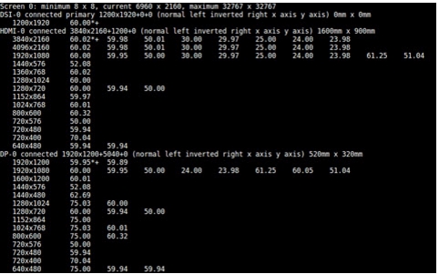
The resulting output shows a list of the HDMI, DP, or DSI display settings, if connected.
3. Switch the resolution to the desired display resolution.
xrandr --output HDMI-0 --mode <res>
xrandr --output DP-0 --mode <res>
Where <res> is the desired resolution, for example, 640x480.
The highest rate supported, for the specified mode, is automatically chosen.
4. Select the desired refresh rate.
xrandr --output HDKI-0 --moe <res> --rate <refresh_rate>
Where <refresh_rate> is the desired refresh rate, for example, 60.
Use xrandr to display all the supported refresh rates for a mode.
Mirroring or Extending Displays
When multiple displays are connected, you can choose the relative position of each monitor (HDMI or DP) or panel (DSI).
To choose the relative position of each monitor
1. Execute the following command to mirror the HDMI monitor with the DSI panel.
xrandr --output HDMI-0 --same-as DSI-0
2. Execute the following command to extend the display environment by placing the HDMI monitor to the left of the DSI panel.
xrandr --output HDMI-0 --left-of DSI-0
3. Execute the following command to place the DP monitor to the right of the DSI panel.
xrandr --output DP-0 --right-of DSI-0
Determining Display Timing Values
This topic describes how to determine the timing values when referring to the LCD specification and the signal polarities. It also describes the constraints for picking the ref_to_sync values.
Display Controller Timing Diagram
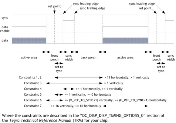
The following diagram shows display controller timing. The diagram relates to both vertical and horizontal timing. Only the back porch can be a negative value, though it is typically positive.
•Back porch—the distance between the trailing edge of the sync and the beginning of the active area. Some LCD specifications define the back porch from the leading edge of the sync rather than the trailing edge.
•Front porch—the distance between the end of the active area and the leading edge of the sync.
•Vertical timing—is in terms of lines.
•Horizontal timing—is in terms of pixels.
•Sync polarity—is in terms of the sync width; active low means the sync width pulse will be low, as in the diagram.
•Pixel clock polarity—is in terms of when data will transition; an active low pixel clock means that the data changes on the falling edge of the clock, to be latched on the rising edge.
•Data enable polarity (also called display enable or DE)—selects the level of the signal during the active area of display. The diagram has DE active high.
Configuring the Display Serial Interface
This topic describes how to configure the Display Serial Interface (DSI). Both the DSI driver and the DSI panel must be configured. Configuring the DSI driver is done through the device tree. Details about display device tree bindings is available at:
<
top>/kernel/kernel-4.4/Documentation/devicetree/bindings/video/nvidia,tegra<
t-arch>-dc.txt
<top>/kernel/kernel-4.4/Documentation/devicetree/bindings/video/nvidia,tegra<t-arch>-dsi.txt
Note: | Configuring the DSI panel requires the panel specification from the vendor. You must use the correct display configuration file for your particular platform. |
To configure the DSI driver
•Locate and edit the appropriate display configuration file depending on your release at:
<top>/hardware/nvidia/platform/tegra/common/kernel-dts/ /panel-<panel_type>.dtsi
Where <panel_type> specifies the characteristics encoded for the panel, using the format:
brand-scrRes-scrSize
For example, the file panel-p-wuxga-10-1.dtsi configures the following panel:
Filename: panel-p-wuxga-10-1.dtsi
brand = p = Panasonic
scrRes = wuxga = WUXGA 1920 x 1200
scrSize = 10-1 = 10.1 inches
The dsi_bindings structure encapsulates all the controller configuration options, specified in files at:
<top>/kernel/kernel-4.4/Documentation/devicetree/bindings/video
The naming format is:
nvidia,tegra<t-arch>-<node_type>.txt
Where <node_type> is dc, hdmi, dp, or dsi.
To configure the DSI panel
1. Configure the regulators.
The details depend on the board schematics.
2. Configure the General-Purpose Input/Outputs (GPIOs) required for resetting and backlighting the panel.
Some panels are more demanding and may require other GPIOs as well.
3. Set up the initialize/suspend sequence.
These are passed as device tree bindings in the power tree for the platform and read in the following file:
<top>/kernel/display/drivers/video/tegra/dc/panel/board-panel.c
Configuring the Display Port
This topic describes how to enable the Display Port (DP), to map DP to a particular display controller (dc), and assign SOR bindings or enable dpaux appropriately.
The base device tree file is available at:
<top>/hardware/nvidia/platfom/t18x/quill/kernel-dts/tegra186-quill-p3310-1000-c03-00-base.dts
Enable the following nodes in this file:
host1x {
nvdisplay@15220000 {
status = “okay”;
nvidia,dc-or-node = "/host1x/sor";
};
sor {
status = “okay”;
dp-display {
status = “okay”;
};
};
dpaux@155c0000 {
status = “okay”;
};
};
Configuring Pulse Width Modulation (PWM)
Backlight control to the panel is done through Pulse Width Modulation (PWM) or Parametric Four-Wave Mixing (PWFM) or through the backlight device embedded in the panel.
The PFW and PFWM driver located at:
<top>/kernel/kernel-4.4/drivers/video/backlight/pwm_bl.c
The driver file for the backlight device embedded in the panel is:
<top>/kernel/kernel-4.4/drivers/video/backlight/xxx.c
For example, the backlight for the LG 5 inch 720p panel on pluto is driven by the embedded max8831 integrated circuit (IC). That driver file is:
<top>/kernel/kernel-4.4/drivers/video/backlight/max8831_bl.c
To make backlight increment in a linear manner to the brightness increment, backlight is calibrated and the corresponding values are stored in the backlight response curve.
Panel Driver and Device Tree
This section points to examples of source files and configuration files for a DSI panel driver.
Internal DSI panel driver and device tree examples
•Driver:
<
top>kernel/display/drivers/video/tegra/dc/panel/panel-a-1200-1920-8-0.c
•Device tree:
Appropriate nodes must be enabled in the device tree. The base device tree file is available at:
<top>/hardware/nvidia/platform/t18x/quill/kernel-dts/tegra186-quill-p3310-1000-c03-00-base.dts
•Enable the DC, DSI, and appropriate panel node.
•Update the dc-or-node property to map DSI to a particular controller as follows:
host1x {
nvdisplay@15200000 {
status = “okay”;
nvidia,dc-or-node = "/host1x/dsi";
};
dsi {
status = “okay”;
panel-s-wuxga-8-0 {
status = “okay”;
};
};
};