Tegra ASoC Driver
The NVIDIA® Tegra® ASoC driver is implemented for the Android and Linux operating systems and is intended to work seamlessly with different Tegra devices, using an existing framework called Advanced Linux Sound Architecture (ALSA), which is maintained by the upstream Linux community.
This topic describes hardware functionality present on Tegra X2 and Jetson TX2. Hardware functionality may not be supported by the software. Review your software documentation to determine availability of software for audio features.
On Jetson TX2, audio output is supported using HDMI audio. Audio input hardware in the development kit is NOT supported.
ALSA
The ALSA framework is a part of the Linux kernel that is supported and maintained by the larger Linux community. This makes it feasible to adapt to the framework, designing a driver that leverages NVIDIA audio routing support. ALSA has a very good collection of sound card drivers, including actual codec drivers for platform ADC and DAC support, and can support adding new codec drivers as well.
ALSA also includes libraries and utilities that enable more refined audio control in Linux and Android user space. These include alsamixer, aplay, arecord, tinycap, and others. This enables you to control audio applications without having to interact with kernel space drivers.
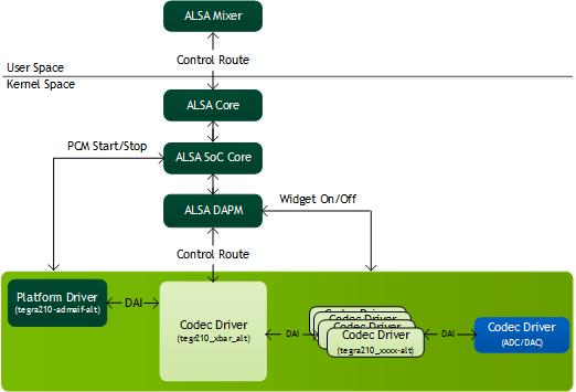
The ALSA software hierarchy is as follows.
User space ALSA applications interact with ALSA core (kernel space) through APIs provided by userspace libraries that initialize the actual hardware codecs at the back end of the audio pipeline.
More information on the ALSA framework is available at the following link:
http://www.alsa-project.org/main/index.php/Main_Page
DAPM
ALSA is designed to support various functionalities including but not limited to dynamic audio routing to the available PCM devices. The component of ALSA core that provides this support is Dynamic Audio Power Management (DAPM). DAPM controls the power flow into and out of various codec blocks in the audio subsystem, thereby minimizing power consumption. DAPM introduces switches or kernel controls in the form of widgets to turn ON/OFF the power of a module and help manipulate the required bit of the specific register dynamically using user space applications such as aplay, arecord, or alsamixer. The widgets are classified into various groups.
More information on the widgets and their applications is available at:
https://www.kernel.org/doc/Documentation/sound/alsa/soc/DPCM.txt
In terms of software hierarchy, DAPM is part of the ALSA core as shown in the
Tegra ASoC Driver Overview diagram, helping to manage the codec module power efficiently.
For details on the clocking and power management in Tegra ASoC driver, see
Clocking and Power Management topic.
For more information see the
Dynamic Audio Routing topic.
Device Tree
The Device Tree is a data structure which describes devices on the platform. It is passed to the operating system at boot time and allows you to avoid hard coding component details in the operating system. In this way it makes it easier to change hardware configurations without rebuilding the kernel.
The data structure contains the name of nodes and properties. Each node can have properties or child nodes, and each property is comprised of a name and more than one value. Device Tree structures must be written in the correct format and according to format rules so that the data structure can be parsed by the operating system.
More details on usage of DTS and its script format can be found at:
For a simple device tree example see the
Codec Driver Instantiation via Device Tree section of this chapter.
Audio Driver
The Tegra Audio Driver leverages Tegra Audio Hub (AHUB) hardware acceleration in the form of platform and codec drivers. The ARM peripheral bus interface (ADMAIF) is implemented as a platform driver with PCM interfaces for playback/record and the rest of the AHUB modules such as the Audio Cross Bar (XBAR), Audio Multiplexer (AMX), Audio Demultiplexer (ADX) and Inter-IC sound (I2S) implemented as codec drivers. Each of the drivers is connected to XBAR through Digital Audio Interfaces (DAIs), inside a machine driver, forming an audio hub.
The machine driver probe instantiates the sound card device and registers all the PCM interfaces as exposed by ADMAIF. After booting, before we can use these interfaces to playback or record audio, you must set up the audio paths inside XBAR. By default, XBAR has no routing connections at boot, and no DAPM path is complete to power on the corresponding widgets. The XBAR driver introduces MUX widgets for all the audio components and enables you to create any custom routing through kcontrol from user space using the alsamixer utility. If the audio path is not complete, the DAPM path is not closed. Hardware settings are not applied and you might not hear any audio output.
For more details on how to set up the route and how to play or record on the PCM interfaces, see the
Audio Playback/Record Examples section of this document.
Tegra Audio Hub
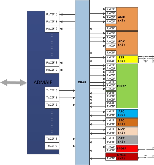
The Tegra audio hub architecture is as follows:
The audio hub contains the modules I2S, SPDIF, and the Digital MIC Controller (DMIC) that interface with the external world. The audio hub also contains Mixer, Sampling Frequency Converter (SFC), Master Volume Control (MVC), Output Processing Engine (OPE), Audio Multiplexers (AMX), Audio Demultiplexers (ADX) and Audio Flow Controllers (AFC). An Audio Direct Memory Access (ADMA) component is included (ADMAIF-DMA) to communicate with memory. The Crossbar (XBAR) facilitates the routing of audio samples through these modules using a proprietary protocol called Audio Client Interface (ACIF).
The modules in the audio hub support various kinds of audio devices that are expected to interface with the application processor, such as cellular baseband devices, different types of audio CODECs, Bluetooth modules, and A/V receivers. The audio hub is capable of supporting the different interface and signal quality requirements of these devices.
Each of the AHUB modules has at least one RX port and one TX port, and some have more than one, depending on whether they are for duplex flow such as I2S. The RX ports feed off from XBAR and the TX ports are fed back into XBAR, except in the case of I2S where one end feeds of the actual codec. This configuration makes XBAR a switch where an audio input can be fed to multiple outputs depending on use case.
For dynamic audio routing examples see the
Audio Playback/Record Examples topic.
Each ADMAIF has both TX and RX FIFOs that support simultaneous recording and playback. ADMA transfers the data to the ADMAIF FIFO for all audio routing scenarios.
For details on hardware configuration of each module, refer to the Tegra Reference Manual.
Software Architecture
The software architecture of the Tegra ASoC driver is very similar to the hardware architecture of the AHUB. This enables you to leverage all the features supported by the hardware and still conform to the ALSA framework. This ALSA System on a Chip (ASoC) driver is comprised of platform, codec and machine drivers.
• Platform driver-This driver is responsible for PCM registration and interfaces with the PCM driver. The ADMAIF is the platform driver.
• Codec driver-Any driver that registers snd_soc_codec_driver structure with the ASoC core can be viewed as the codec driver. The module must have at least one input and one output. In addition, the structure provides a way to define your own DAPM widgets for power management and also kcontrols for register setting from user space. All other modules except ADMAIF are implemented as codec drivers.
• Machine driver-This driver connects one or more codec drivers and a PCM driver together for a given platform.
For details on how to write a machine driver and identify a sound card, see the
Tegra Machine Driver topic and the kernel documentation for AsoC framework at:
https://www.kernel.org/doc/Documentation/sound/alsa/soc/
Tegra Platform Driver
The Tegra platform driver realizes the number of ports of playback and capture possible inside the AHUB. Some or all of these ports can connected to form a full audio routing path. You must complete these paths as described in
Audio Playback/Record Examples.
ADMAIF
In the Tegra ASoC driver, ADMAIF is implemented as a platform driver and interfaces with the PCM driver. The PCM driver helps perform DMA operations by overriding the function pointers exposed by the snd_pcm_ops structure. The PCM driver is platform agnostic and interacts only with the SOC DMA engine upstream APIs. The DMA engine then interacts with the platform specific DMA driver to get the correct DMA settings. The ADMAIF platform driver defines DAIs and registers the same with ASoC core.
In Tegra X2, there are 10 ADMAIFs. Each ADMAIF is bi-directional, facilitating 10 streams of playback and 10 streams of capture.
Playback Hardware Devices in the Tegra ASoC Driver
**** List of PLAYBACK Hardware Devices ****
card 0: tegrasndt210ref [tegra-snd-t210ref], device 0: ADMAIF1 CIF ADMAIF1-0 []
Subdevices: 1/1
Subdevice #0: subdevice #0
card 0: tegrasndt210ref [tegra-snd-t210ref], device 1: ADMAIF2 CIF ADMAIF2-1 []
Subdevices: 1/1
Subdevice #0: subdevice #0
card 0: tegrasndt210ref [tegra-snd-t210ref], device 2: ADMAIF3 CIF ADMAIF3-2 []
Subdevices: 1/1
Subdevice #0: subdevice #0
card 0: tegrasndt210ref [tegra-snd-t210ref], device 3: ADMAIF4 CIF ADMAIF4-3 []
Subdevices: 1/1
Subdevice #0: subdevice #0
card 0: tegrasndt210ref [tegra-snd-t210ref], device 4: ADMAIF5 CIF ADMAIF5-4 []
Subdevices: 1/1
Subdevice #0: subdevice #0
card 0: tegrasndt210ref [tegra-snd-t210ref], device 5: ADMAIF6 CIF ADMAIF6-5 []
Subdevices: 1/1
Subdevice #0: subdevice #0
card 0: tegrasndt210ref [tegra-snd-t210ref], device 6: ADMAIF7 CIF ADMAIF7-6 []
Subdevices: 1/1
Subdevice #0: subdevice #0
card 0: tegrasndt210ref [tegra-snd-t210ref], device 7: ADMAIF8 CIF ADMAIF8-7 []
Subdevices: 1/1
Subdevice #0: subdevice #0
card 0: tegrasndt210ref [tegra-snd-t210ref], device 8: ADMAIF9 CIF ADMAIF9-8 []
Subdevices: 1/1
Subdevice #0: subdevice #0
card 0: tegrasndt210ref [tegra-snd-t210ref], device 9: ADMAIF10 CIF ADMAIF10-9[]
Subdevices: 1/1
Subdevice #0: subdevice #0
card 0: tegrasndt210ref [tegra-snd-t210ref], device 93: ADSP PCM ADSP-FE1-93 []
Subdevices: 1/1
Subdevice #0: subdevice #0
Capture Hardware Devices in the Tegra ASoC Driver
**** List of CAPTURE Hardware Devices ****
card 0: tegrasndt210ref [tegra-snd-t210ref], device 0: ADMAIF1 CIF ADMAIF1-0 []
Subdevices: 1/1
Subdevice #0: subdevice #0
card 0: tegrasndt210ref [tegra-snd-t210ref], device 1: ADMAIF2 CIF ADMAIF2-1 []
Subdevices: 1/1
Subdevice #0: subdevice #0
card 0: tegrasndt210ref [tegra-snd-t210ref], device 2: ADMAIF3 CIF ADMAIF3-2 []
Subdevices: 1/1
Subdevice #0: subdevice #0
card 0: tegrasndt210ref [tegra-snd-t210ref], device 3: ADMAIF4 CIF ADMAIF4-3 []
Subdevices: 1/1
Subdevice #0: subdevice #0
card 0: tegrasndt210ref [tegra-snd-t210ref], device 4: ADMAIF5 CIF ADMAIF5-4 []
Subdevices: 1/1
Subdevice #0: subdevice #0
card 0: tegrasndt210ref [tegra-snd-t210ref], device 5: ADMAIF6 CIF ADMAIF6-5 []
Subdevices: 1/1
Subdevice #0: subdevice #0
card 0: tegrasndt210ref [tegra-snd-t210ref], device 6: ADMAIF7 CIF ADMAIF7-6 []
Subdevices: 1/1
Subdevice #0: subdevice #0
card 0: tegrasndt210ref [tegra-snd-t210ref], device 7: ADMAIF8 CIF ADMAIF8-7 []
Subdevices: 1/1
Subdevice #0: subdevice #0
card 0: tegrasndt210ref [tegra-snd-t210ref], device 8: ADMAIF9 CIF ADMAIF9-8 []
Subdevices: 1/1
Subdevice #0: subdevice #0
card 0: tegrasndt210ref [tegra-snd-t210ref], device 9: ADMAIF10 CIF ADMAIF10-9[]
Subdevices: 1/1
Subdevice #0: subdevice #0
card 0: tegrasndt210ref [tegra-snd-t210ref], device 93: ADSP PCM ADSP-FE1-93 []
Subdevices: 1/1
Subdevice #0: subdevice #0
Tegra Codec Driver
A small overview of codec drivers is presented in the
Tegra Audio Hub section of this document. In the Tegra ASoC driver implementation, the rest of the AHUB modules, except ADMAIF, are implemented as codec drivers.
Their responsibilities include:
• Interface to other modules by defining DAIs.
• Define DAPM widgets and establish DAPM routes for dynamic power switching.
• Expose additional kcontrols (kernel controls) as needed for user space utilities to dynamically control module behavior.
XBAR
The XBAR codec driver defines RX, TX and MUX widgets for all the interfacing modules such as ADMAIF, AMX, ADX, I2S, SPDIF, DMIC, Mixer, SFC, MVC, OPE and AFC. MUX widgets are permanently routed to the corresponding TX widgets inside the snd_soc_dapm_route structure.
However, the XBAR interconnections are made by connecting any RX widget block to any MUX widget block as needed using the alsamixer utility. The get/put handlers for these widgets are implemented so that audio connections are stored by setting the appropriate bit in the hardware MUX register.
For more information see the
Audio Playback/Record Examples topic and the
Dynamic Audio Routing topic.
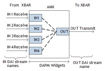
AMX
An Audio Multiplexer (AMX) module can multiplex up to 4 streams of 16 channels, 32 bits each, into one time-division multiplexed (TDM) stream of 16 channels and 32 bits. The 4 RX ports of AMX originate from XBAR and 1 TX port feeds into XBAR. The DAPM widgets exposed are as shown in the following diagram. The DAPM routes established using these widgets are shown in the dotted lines.
The AMX Codec Driver Internals are as follows:
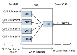
ADX
An Audio Demultiplexer (ADX) module can de-multiplex a single TDM stream of 16 channels and 32 bits into 4 streams of up to 16 channels, 32 bits each. The 1 RX port of ADX originates from XBAR and 4 TX ports feeds into XBAR. The DAPM widgets exposed are as shown in the following diagram. The DAPM routes established using these widgets are shown in the dotted lines.
The ADX Codec Driver Internals is as follows:
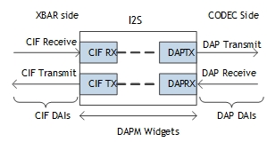
I2S
An I2S module supports 6 different modes, the most useful of which are I2S and TDM. When I2S is configured in TDM mode, we can use AMX and ADX for multiplexing and demultiplexing audio streams. I2S module can also be in I2S mode if the physical codec interfaced does not support TDM mode of operation. An I2S codec driver supports bidirectional data flow and thus defines CIF and DAP RX/TX widgets as shown in the following diagram. The CIF side of I2S, interfaces with XBAR and DAP side is meant to interface with the physical codec on the given platform. The DAPM routes established using these widgets are shown in the dotted lines. I2S modules also expose kernel control to enable internal I2S loopback.
The I2S Codec Driver Internals is as follows:
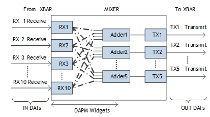
Mixer
The Mixer can mix audio streams from any of the 10 XBAR-originating input ports to any of the 5 output ports. The DAPM widgets and routes for Mixer are shown in the following diagram. The Mixer driver also exposes Rx Gain and Mixer Enable as additional kcontrols to set the volume of each input stream and to globally enable or disable the Mixer itself.
The Mixer Codec Driver Internals is as follows:
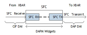
SFC
The Sampling Frequency Converter(SFC) can convert the input sampling frequency to the required sampling rate. SFC has one input port and one output port which are connected to XBAR. The DAPM widgets and routes for SFC are as follows:
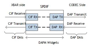
SPDIF
The SPDIF driver is very similar to I2S in terms of the DAPM widgets that are exposed and the routing setup. SPDIF is also bidirectional and adapts to the sampling rate of the incoming data. It is implemented as follows:
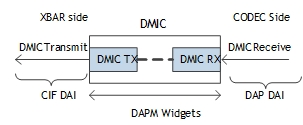
DMIC
It is beneficial to interface directly to digital microphones and speakers via pulse-density modulation (PDM), thus avoiding the need for a PDM-capable external codec. The DMIC controller implements a converter to convert PDM (Pulse density modulation) signals to PCM (Pulse code modulation) signals. The DAPM widgets and routes are as follows.
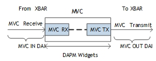
MVC
MVC provides gain or attenuation to a digital signal path. The digital volume control block is a generic block. It can be used in input or output digital signal path. It can also be used for per-stream volume control and master volume control. The DAPM widgets and routes as follows.
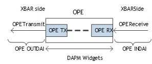
OPE
The Output Processing Engine (OPE) is a client of AHUB. OPE contains PEQ and MBDRC which have a scalable number of BiQuad stages, support stereo, 5p1 and 7p1 channels, and meet ultra-low power(ULP) audio requirements. The DAPM widgets and routes are as follows.
Tegra Machine Driver
The Tegra machine driver connects the codec drivers by linking the DAIs exposed by each module described in previous chapter. It defines the snd_soc_dai_link structure and instantiates the sound card.
In general, machine driver responsibilities include:
• Populate the snd_soc_dai_link structure with appropriate CPU and CODEC DAIs
• Physical codec clock setting (if any) and codec initializations
• Master/slave configurations (if any)
• Define DAPM widgets to route through the physical codec internals and complete DAPM path as needed
• Propagate the runtime sampling frequency to the individual codec drivers as needed
To adapt the generic machine driver template to a given platform, you must initialize the platform data structure in the device tree structure file shown below. It is important to gather some information about the hardware platform. You must identify the physical codecs present on board and the I2S instance they interface with in the hardware. Refer to hardware schematics for the platform to obtain this information.
sound_ref {
compatible = " ";
nvidia,model = " ";
nvidia,num-codec-link = < >;
nvidia,num-amx = < >;
nvidia,num-adx = < >;
nvidia,amx-slot-size = < >;
nvidia,adx-slot-size = < >;
nvidia,amx-slot-map = < >;
nvidia,adx-slot-map = < >;
nvidia,audio-routing = ;
nvidia,xbar = <&tegra_axbar>;
nvidia,dai-link-1 {
link-name = " ";
cpu-dai = < >;
codec-dai = < >;
cpu-dai-name = " ";
codec-dai-name = " ";
tx-mask = < >;
rx-mask = < >;
format = " ";
bitclock-slave;
frame-slave;
bitclock-noninversion;
frame-noninversion;
bit-format = " ";
bclk_ratio = < >;
srate = < >;
num-channel = < >;
name-prefix = " ";
};
};
The sound node is added to the DT file for sound card registration and passing platform related data. To bind a device driver to a specific device in a DT file, each node must define a compatible property, which is a list of strings. The optional nvidia,model property is used for the sound card name. The nvidia,num-codec-link property shows the number of dai links exposed outside of the Tegra devices such as I2S, SPDIF or DMIC. This is the same as the number of nvidia,dai-link-<number> child nodes.
In Tegra X2 devices, each AMX and ADX has two modules, nvidia,num-amx and nvidia,num-adx. These indicate the total number of AMX and ADX to be registered by the machine driver. The nvidia,amx-slot-size and nvidia,adx-slot-size properties indicate the slot map size of each module, which is related to the size of nvidia,amx-slot-map and nvidia,adx-slot-map. The machine driver uses the default value for each property to support stereo 16 bits while initiating AMX and ADX modules unless the above properties are overridden.
The nvidia,dai-link-<number> node is initialized based on I2S and physical codec links as shown above. You can replace the codec with a dummy spdif-dit.0 codec. In that case, you must program the physical codecs at the required sampling rate and operational modes either through a separate utility or by adding necessary hw_params API calls inside the machine driver. The link-name property represents each DAI link, and differentiates the codecs connected to the different I2S instances.
The bitclock-slave, frame-slave, format, bitclock-noninverstion and frame-noninversion properties set I2S in I2S/TDM formats and/or master/slave modes. The bclk-ratio property is available to configure the I2S bit clock sample rate. The srate and num-channel properties indicate I2S LRCK and the number of channels in one frame. DAPM routes are initialized as established in nvidia,audio-routing property.
To populate the snd_soc_dai_link structure in the machine driver
1. Initialize all XBAR related DAI links common to any machine driver. Use the APIs in the utility file tegra_asoc_machine_alt.h in the machine driver probe function as shown in the following example:
/* get the xbar dai link structure */
tegra_machine_dai_links=
tegra_machine_get_dai_link();
/* set AMX/ADX dai_init */
tegra_machine_set_dai_init(TEGRA210_DAI_LINK_AMX1,
&tegra_t210ref_amx1_dai_init);
tegra_machine_set_dai_init(TEGRA210_DAI_LINK_ADX1,
&tegra_t210ref_adx1_dai_init);
tegra_machine_set_dai_init(TEGRA210_DAI_LINK_AMX2,
&tegra_t210ref_amx2_dai_init);
tegra_machine_set_dai_init(TEGRA210_DAI_LINK_ADX2,
&tegra_t210ref_adx2_dai_init);
/* set sfc dai_init */
tegra_machine_set_dai_init(TEGRA210_DAI_LINK_SFC1_RX,
&tegra_t210ref_sfc1_init);
tegra_machine_set_dai_init(TEGRA210_DAI_LINK_SFC2_RX,
&tegra_t210ref_sfc2_init);
tegra_machine_set_dai_init(TEGRA210_DAI_LINK_SFC3_RX,
&tegra_t210ref_sfc3_init);
tegra_machine_set_dai_init(TEGRA210_DAI_LINK_SFC4_RX,
&tegra_t210ref_sfc4_init);
2. The generic machine driver handles DAI link management based on the initialized platform specific data in the DT file.
Because this step is platform/machine dependent, it is discussed with an example in subsequent sections of this chapter.
Tegra X2
In the Tegra X2 combination of boards, there is one available AD1937s codec. AD1937 supports eight channels in TDM and I2S modes, respectively. The AD1937 codec is connected to I2S4 on P1892.
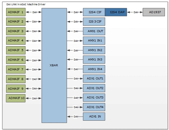
Machine Specific DAI links
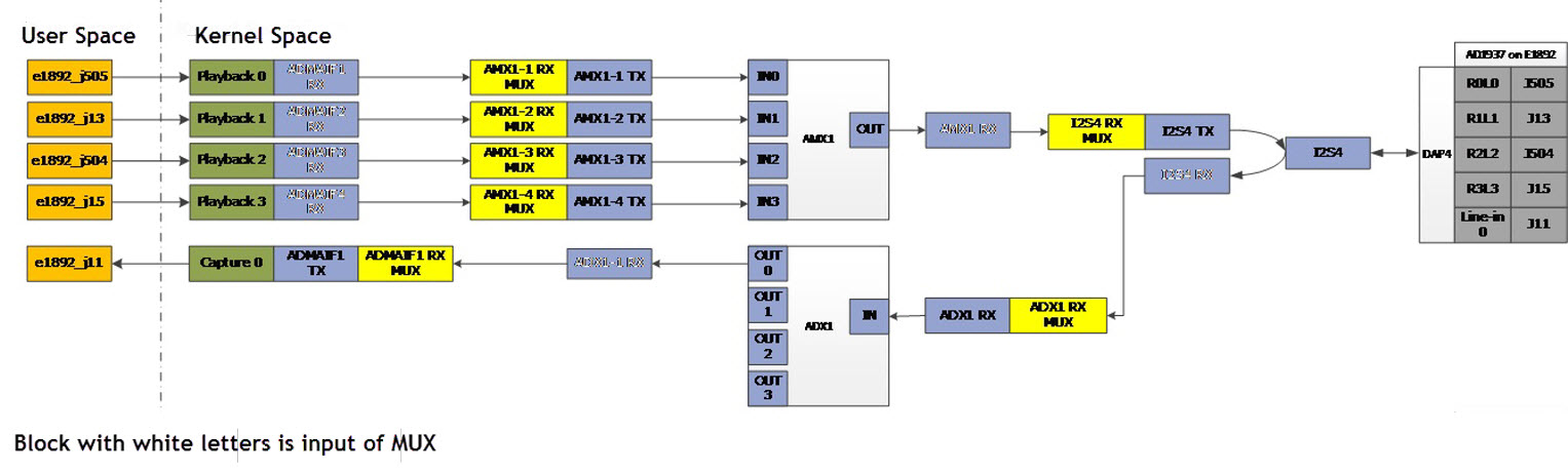
The platform data structure must be initialized in the DT file so that the machine driver can retrieve the device specific information during the platform probe. The DAI link diagram for PEDP+ with Tegra X2, where the left side of each DAI is CPU DAI, and right side of each DAI is codec DAI in snd_soc_dai_link, is as follows.
sound_ref {
compatible = "nvidia,tegra-audio-t210ref";
nvidia,model = "tegra-snd-t210ref";
nvidia,num-codec-link = <1>;
nvidia,num-amx = <1>;
nvidia,num-adx = <1>;
nvidia,amx-slot-size = <32 32>;
nvidia,adx-slot-size = <32 32>;
nvidia,addr-max9485 = <112>;
nvidia,amx-slot-map = <
/* jack 0 */
TDM_SLOT_MAP(0, 0, 0)
TDM_SLOT_MAP(0, 0, 0)
TDM_SLOT_MAP(0, 1, 0)
TDM_SLOT_MAP(0, 1, 1)
TDM_SLOT_MAP(0, 0, 0)
TDM_SLOT_MAP(0, 0, 0)
TDM_SLOT_MAP(0, 2, 0)
TDM_SLOT_MAP(0, 2, 1)
/* jack 1 */
TDM_SLOT_MAP(0, 0, 0)
TDM_SLOT_MAP(0, 0, 0)
TDM_SLOT_MAP(1, 1, 0)
TDM_SLOT_MAP(1, 1, 1)
TDM_SLOT_MAP(0, 0, 0)
TDM_SLOT_MAP(0, 0, 0)
TDM_SLOT_MAP(1, 2, 0)
TDM_SLOT_MAP(1, 2, 1)
/* jack 2 */
TDM_SLOT_MAP(0, 0, 0)
TDM_SLOT_MAP(0, 0, 0)
TDM_SLOT_MAP(2, 1, 0)
TDM_SLOT_MAP(2, 1, 1)
TDM_SLOT_MAP(0, 0, 0)
TDM_SLOT_MAP(0, 0, 0)
TDM_SLOT_MAP(2, 2, 0)
TDM_SLOT_MAP(2, 2, 1)
/* jack 3 */
TDM_SLOT_MAP(0, 0, 0)
TDM_SLOT_MAP(0, 0, 0)
TDM_SLOT_MAP(3, 1, 0)
TDM_SLOT_MAP(3, 1, 1)
TDM_SLOT_MAP(0, 0, 0)
TDM_SLOT_MAP(0, 0, 0)
TDM_SLOT_MAP(3, 2, 0)
TDM_SLOT_MAP(3, 2, 1)>;
nvidia,adx-slot-map = <
/* jack 0 */
TDM_SLOT_MAP(0, 0, 0)
TDM_SLOT_MAP(0, 0, 0)
TDM_SLOT_MAP(0, 1, 0)
TDM_SLOT_MAP(0, 1, 1)
TDM_SLOT_MAP(0, 0, 0)
TDM_SLOT_MAP(0, 0, 0)
TDM_SLOT_MAP(0, 2, 0)
TDM_SLOT_MAP(0, 2, 1)
/* jack 1 */
TDM_SLOT_MAP(0, 0, 0)
TDM_SLOT_MAP(0, 0, 0)
TDM_SLOT_MAP(1, 1, 0)
TDM_SLOT_MAP(1, 1, 1)
TDM_SLOT_MAP(0, 0, 0)
TDM_SLOT_MAP(0, 0, 0)
TDM_SLOT_MAP(1, 2, 0)
TDM_SLOT_MAP(1, 2, 1)
/* jack 2 */
TDM_SLOT_MAP(0, 0, 0)
TDM_SLOT_MAP(0, 0, 0)
TDM_SLOT_MAP(2, 1, 0)
TDM_SLOT_MAP(2, 1, 1)
TDM_SLOT_MAP(0, 0, 0)
TDM_SLOT_MAP(0, 0, 0)
TDM_SLOT_MAP(2, 2, 0)
TDM_SLOT_MAP(2, 2, 1)
/* jack 3 */
TDM_SLOT_MAP(0, 0, 0)
TDM_SLOT_MAP(0, 0, 0)
TDM_SLOT_MAP(3, 1, 0)
TDM_SLOT_MAP(3, 1, 1)
TDM_SLOT_MAP(0, 0, 0)
TDM_SLOT_MAP(0, 0, 0)
TDM_SLOT_MAP(3, 2, 0)
TDM_SLOT_MAP(3, 2, 1)>;
nvidia,audio-routing =
"Headphone-z", "z DAC1OUT",
"Headphone-z", "z DAC2OUT",
"Headphone-z", "z DAC3OUT",
"Headphone-z", "z DAC4OUT",
"z ADC1IN", "LineIn-z";
nvidia,xbar = <&tegra_axbar>;
nvidia,dai-link-1 {
link-name = "ad-playback-z";
cpu-dai = <&tegra_i2s4>;
codec-dai = <&ad1937z>;
cpu-dai-name = "I2S4";
codec-dai-name = "ad193x-hifi";
tx-mask = <0xFF>;
rx-mask = <0xFF>;
format = "dsp_a";
bitclock-slave;
frame-slave;
bitclock-noninversion;
frame-noninversion;
bit-format = "s32_le";
bclk_ratio = <1>;
srate = <48000>;
num-channel = <8>;
name-prefix = "z";
};
};
The dai_fmt sets I2S4 in TDM master mode. It also connects codec AD1937 with I2S4 DAPM routes and AMX/ADX slot maps initialized. The sound card is named tegra-snd-t210ref.
The DAPM widgets supported in the generic machine driver include Headphone-x, Headphone-y, Headphone-z, Headphone-s, LineIn-x, LineIn-y, LineIn-z, and LineIn-s. Based on how name_prefix and dai_fmt are initialized, the DAPM route must be set by parsing the IN/OUT DAPM widgets of the physical codec. Without this, the DAPM path is not complete and audio does not function correctly. The Tegra X2 audio map is shown below.
nvidia,audio-routing =
"Headphone-z", "z DAC1OUT",
"Headphone-z", "z DAC2OUT",
"Headphone-z", "z DAC3OUT",
"Headphone-z", "z DAC4OUT",
"z ADC1IN", "LineIn-z",
Though we can assign any ADMAIF to any AMX via XBAR, we can fix ADMAIF1 to ADMAIF4 as the inputs of AMX1 are connected to I2S4.
The machine driver creates three snd_soc_dai_links for each dai-link-<number> node initialized in the DT file and appends them to XBAR DAI links using the utility API. It also initializes the .dai_ops for the ADMAIF interfaces accordingly as shown below.
/* set ADMAIF dai_ops */
for (i = TEGRA210_DAI_LINK_ADMAIF1;
i <= TEGRA210_DAI_LINK_ADMAIF10; i++)
tegra_machine_set_dai_ops(i, &tegra_t210ref_spdif_ops);
for (i = 0; i < machine->num_codec_links; i++) {
if (tegra_t210ref_codec_links[i].name) {
if (strstr(tegra_t210ref_codec_links[i].name,
"ad-playback-z")) {
for (j = TEGRA210_DAI_LINK_ADMAIF1;
j <= TEGRA210_DAI_LINK_ADMAIF4; j++)
tegra_machine_set_dai_ops(j,
&tegra_t210ref_ad1937_z_ops);
} else if (strstr(tegra_t210ref_codec_links[i].name,
"ad-playback-x")) {
for (j = TEGRA210_DAI_LINK_ADMAIF5;
j <= TEGRA210_DAI_LINK_ADMAIF8; j++)
tegra_machine_set_dai_ops(j,
&tegra_t210ref_ad1937_x_ops);
} else if (strstr(tegra_t210ref_codec_links[i].name,
"spdif-playback")) {
tegra_machine_set_dai_ops(
TEGRA210_DAI_LINK_ADMAIF9,
&tegra_t210ref_spdif_ops);
}
}
}
/* append t210ref specific dai_links */
card->num_links =
tegra_machine_append_dai_link(tegra_t210ref_codec_links,
2 * machine->num_codec_links);
tegra_machine_dai_links = tegra_machine_get_dai_link();
card->dai_link = tegra_machine_dai_links;
Tegra X2 Audio Path
The dai_link connection in the machine driver only connects the platform and codec drivers to XBAR driver. However, to realize any audio output from the physical codecs, you must complete the DAPM path by routing through the internals of XBAR, i.e., connect the RX and MUX widgets.from user space using alsamixer utility as follows.
XBAR Route Setting for Tegra X2
amixer -c 0 sset 'I2S4 Mux' 'AMX1'
amixer -c 0 sset 'AMX1-1 Mux' 'ADMAIF1'
amixer -c 0 sset 'AMX1-2 Mux' 'ADMAIF2'
amixer -c 0 sset 'AMX1-3 Mux' 'ADMAIF3'
amixer -c 0 sset 'AMX1-4 Mux' 'ADMAIF4'
amixer -c 0 sset 'ADX1 Mux' 'I2S4'
amixer -c 0 sset 'ADMAIF1 Mux' 'ADX1-1'
Dynamic Audio Routing
Instantiation of the sound card after boot indicates that all codec drivers and the platform driver are interconnected using the machine driver. The remaining step before obtaining the audio output on the physical codecs involves routing through the XBAR internals via MUX widgets to complete the DAPM path using the alsamixer utility. To support audio routing dynamically between AHUB modules, this route setting step is performed from user space. This provides flexibility for complicated use cases.
For example, [amixer -c 0 sset ‘I2S1 Mux’ ‘I2S1’] realizes the internal AHUB path I2S1 RX -> XBAR -> I2S1 TX. Similarly, the following are use cases that emphasize dynamic audio route control from user space.
Case 1: Internal AHUB TDM Path
Path: I2S -> ADX -> AMX -> I2S
Commands:
amixer -c 0 sset ‘ADX1 Mux’ ‘I2S4’
amixer -c 0 sset ‘AMX1-1 Mux’ ‘ADX1-1’
amixer -c 0 sset ‘AMX1-2 Mux’ ‘ADX2-2’
amixer -c 0 sset ‘AMX1-3 Mux’ ‘ADX3-3’
amixer -c 0 sset ‘AMX1-4 Mux’ ‘ADX4-4’
amixer -c 0 sset 'I2S4 Mux' 'AMX1'
To modify Case 1 to record on I2S3 (I2S Mode) and output on I2S4 (TDM Mode)
Path: [I2S -> ADX -> AMX -> I2S] + [I2S3 -> AMX -> I2S4]
Initially audio records from I2S4 and outputs on I2S4.
Commands:
amixer -c 0 sset ‘AMX1-1 Mux’ ‘None’
amixer -c 0 sset ‘AMX1-1 Mux’ ‘I2S3’
After this step, audio records from I2S3 and outputs on I2S4
Codec Driver Instantiation Using Device Tree
Based on architecture, the Makefile in the following directory conditionally compiles the required DTS files into DTB files:
$KERNEL_TOP/arch/arm64/boot/dts/
When the kernel is flashed, the flash script chooses the required DTS file for parsing during boot, and the ASoC codecs listed in DTS are instantiated. To add any new module instantiation as a requirement, identify and edit the Device Tree script as reported in the dmesg log on the target as shown in the following example:
<6>[ 0.000000] Tegra reserved memory:
<6>[ 0.000000] LP0: f25ff000 - f25fffff
<6>[ 0.000000] Bootloader framebuffer: 00000000 - 00000000
<6>[ 0.000000] Bootloader framebuffer2: 00000000 - 00000000
<6>[ 0.000000] Framebuffer: ef800000 - f09fffff
<6>[ 0.000000] 2nd Framebuffer: f0a00000 - f19fffff
<6>[ 0.000000] Carveout: 00000000 - 00000000
<6>[ 0.000000] Vpr: f4600000 - ffffffff
<6>[ 0.000000] Tsec: 00000000 - 00000000
<7>[ 0.000000] On node 0 totalpages: 980992
<7>[ 0.000000] DMA32 zone: 6244 pages used for memmap
<7>[ 0.000000] DMA32 zone: 0 pages reserved
<7>[ 0.000000] DMA32 zone: 456704 pages, LIFO batch:31
<7>[ 0.000000] Normal zone: 7168 pages used for memmap
<7>[ 0.000000] Normal zone: 524288 pages, LIFO batch:31
<6>[ 0.000000] psci: probing function IDs from device-tree
<6>[ 0.000000] DTS File Name: /home/juskim/git/android/t210_main/kernel/arch/arm64/boot/dts/tegra210-ers-E2581-1100-a00-00.dts
<6>[ 0.000000] Tegra21: Speedo/IDDQ fuse revision 0
To add new devices for instantiation
• Add the device name with the base address and status as “okay”, as shown in the following example.
ahub {
status = "okay";
i2s@702d1000 {
pinctrl-names = "dap_active", "dap_inactive";
pinctrl-0 = <>;
pinctrl-1 = <>;
status = "okay";
};
};
TDM Slot Mapping
The Tegra X2 AHUB consists of 2 hardware audio multiplexers (AMX) and demultiplexers (ADX) as described in
Tegra Audio Hub. Initialize slot mapping in the platform data as shown in
Machine Specific DAI links. Without any initialization, the machine driver defaults the slot map for AMX inputs and ADX outputs at 16-bit stereo and 8-channel, 32 bit TDM output. To change the slot mapping of hardware TDMs, adjust the slot map structures in the DT file.
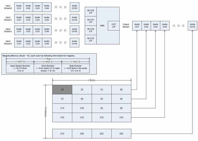
The AMX can multiplex up to 4 input streams, each of which can be up to 16 channels, 32 bits, into 1 single output stream of 16 channels, 32 bits to form a TDM signal. The capability of ADX is the reverse of AMX.
The slot map is an integer array of size 32 that controls the mapping of these input streams to the output stream. The following macro is available:
#define TDM_SLOT_MAP(stream_id, nth_channel, nth_byte) \
((stream_id << 16) | (nth_channel << 8) | (nth_byte))
where stream_id can vary from 0 to 3, nth_channel can vary from 1 to 16, and nth_byte can vary from 0 to 3.
Clocking and Power Management
The clock tree of the Tegra ASoC driver in the idle state, when no audio record or playback is in progress, is as shown below.
clock state ref div rate
--------------------------------------------------------------
i2s4_sync on 1 24000000
i2s3_sync on 1 24000000
*audio3 off 0 24000000
i2s2_sync on 1 24000000
i2s1_sync on 1 24000000
*audio1 off 0 24000000
i2s0_sync on 1 24000000
spdif_in_sync on 1 24000000
*audio2_dmic off 0 24000000
*audio1_dmic off 0 24000000
*audio0_dmic off 0 24000000
*audio off 0 24000000
*audio_2x off 0 x2 48000000
*audio4 off 0 24000000
*audio2 off 0 24000000
*audio0 off 0 24000000
osc on 3 38400000
pll_ref on 7 1.0 38400000
pll_a on 1 x9.5 368639844
pll_a_out0 on 1 15.0 24575990
extern1 on 3 1.0 24575990
clk_out_1 on 2 1.0 24575990
d_audio off 0 2.0 12287995
*dmic3 off 0 11.0 2234181
*dmic2 off 0 11.0 2234181
*dmic1 off 0 11.0 2234181
spdif_out off 0 21.0 1170286
i2s4 off 0 5.5 4468362
i2s3 off 0 5.50 4468362
i2s1 off 0 5.50 4468362
i2s0 off 0 10.50 2340571
pll_p on 15 x10.6 408000000
*spdif_in off 0 8.50 48000000
ape off 0 2.0 204000000
xbar.ape off 0 204000000
adsp.ape off 0 204000000
adma.ape off 0 204000000
The clocks of the individual modules, AMX, ADX, AFC, SFC, MIXER, and others, are internally handled by the APE clock. The clock for the codec drivers I2S and XBAR are switched OFF in idle. They are turned ON when audio playback or recording is in progress. The idle_bias_off option provided by ASoC core (snd_soc_codec_driver) is set to 1 in the individual codec drivers for dynamic audio power management. With this option, the ASoC core calls the appropriate resume() and suspend() functions in the codec driver that was registered using SET_RUNTIME_PM_OPS during platform probe.
The suspend and resume APIs are called when playback or record stops or starts. The suspend API caches the register map and disables the clock. The resume API enables the clock and then syncs the register map from the cache.
Note: | Volatile registers are not synced in this process. Those registers must be reprogrammed after the clock is re-enabled. The internal mapping RAM FIFOs, if any, are cleared during every suspend/resume cycle. The RAM configuration must be restored as well during this process. |
Audio Playback/Record Examples
To test audio playback and record scenarios, make sure the XBAR route is set up using alsamixer commands, based on the platform. The following provides the sample testing commands for audio playback and record scenarios.
Command | Result |
aplay -D AUDIO_OUT0 sample.wav | Audio output from AUDIO_OUT0 on e1892. |
aplay -D AUDIO_OUT1 sample.wav | Audio output from AUDIO_OUT1 on e1892. |
aplay -D AUDIO_OUT2 sample.wav | Audio output from AUDIO_OUT2 on e1892. |
aplay -D AUDIO_OUT3 sample.wav | Audio output from AUDIO_OUT3 on e1892. |
arecord -D AUDIO_IN -f dat -d 30 record_result.wav | Audio recorded as input from AUDIO_IN on E1892 and saved to file record_result.wav. |
Troubleshooting
Issue 1: No Sound Cards Found
• Identify the ASoC error that lead to no sound card detection with the dmesg [dmesg | grep ASoC] command. Output is similar to the following:
[4.874720] tegra-audio-t210ref tegra-audio-t210ref.0: ASoC: no source widget found for x OUT
[4.874724] tegra-audio-t210ref tegra-audio-t210ref.0: ASoC: Failed to add route x OUT-> direct-> Headphone-x
[4.874736] tegra-audio-t210ref tegra-audio-t210ref.0: ASoC: no sink widget found for x IN
[4.874739] tegra-audio-t210ref tegra-audio-t210ref.0: ASoC: Failed to add route LineIn-x-> direct-> x IN
In this case, x OUT and x IN are the widgets of the spdif-dit dummy codec. It might have not been instantiated in ASoC. Confirm that with the following command:
cat /sys/kernel/debug/asoc/codecs
if spdif-dit is instantiated. The spdif device must be instantiated using platform_register in the board-specific file.
• If output from the dmesg [dmesg | grep ASoC] command is similar to the following:
[4.874720] tegra-audio-t210ref tegra-audio-t210ref.0: ASoC: CPU DAI DAP not registered
In this case, “DAP” is the CPU DAI for the I2S to codec dai link. The I2S codec may not be instantiated in ASoC. Confirm that with the following command:
cat /sys/kernel/debug/asoc/codecs
if tegra30-i2s is instantiated.
Identification of the DAI link at the point of failure would give a clue on the I2S instance number that failed to instantiate. Accordingly, the I2S codec driver can be instantiated by providing a suitable entry point in DTS file as described in
Codec Driver Instantiation via Device Tree.
Issue 2: Sound Not Audible
1. Confirm if the DAPM path is completed. Check the path using alsamixer utility as described in
Audio Path.
2. Confirm the pinmux setting for I2S master/slave mode. Check the following files.
arch/arm64/boot/dts/tegra210-foster-e-p2530-common.dtsi
arch/arm64/boot/dts/tegra210-platforms/tegra210-foster-e-pinmux-p2530-0930-e00.dtsi
3. Confirm the status property of i2s is set to okay in the following file:
arch/arm64/boot/dts/tegra210-common.dtsi
4. Confirm the clock settings for I2S master/slave mode. Probe the Frame sync (FS) and bit clock (BCLK) of I2S using a scope.
5. If I2S is configured in TDM mode, please check whether the AMX slot map is configured correctly based on the description in
TDM Slot Mapping.
6. You can also form an internal DAPM path connecting I2S with the same I2S instance using the following command:
amixer -c 0 sset ‘I2S Mux’ ‘I2S’
If the codec record/playback functions correctly, that confirms I2S and onboard codecs are configured correctly. It also isolates the problem to rest of the AHUB path.
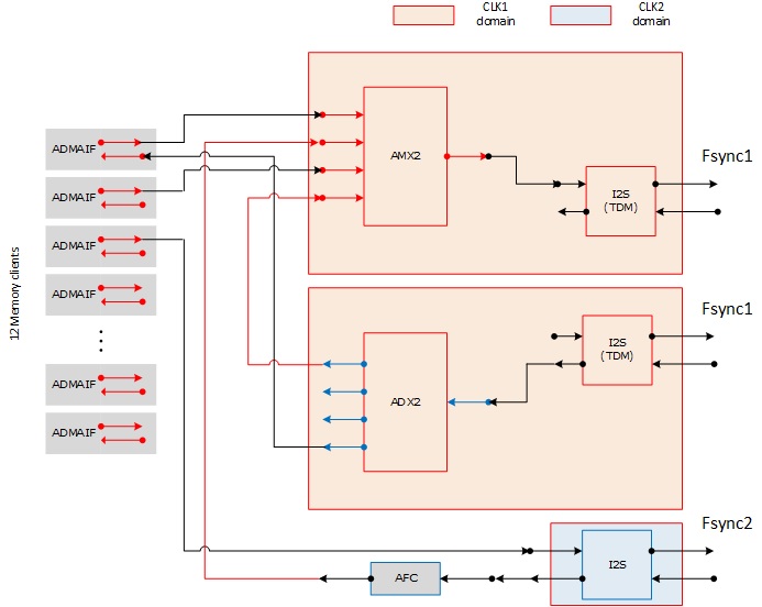
Simple Internal Audio Path Example
• AMX connection routing commands:
amixer -c 0 sset 'AMX2-1 Mux' 'ADMAIF5'
amixer -c 0 sset 'AMX2-2 Mux' 'AFC1'
amixer -c 0 sset 'AMX2-3 Mux' 'ADMAIF6'
amixer -c 0 sset 'AMX2-4 Mux' 'ADX2-1'
amixer -c 0 sset 'I2S3 Mux' 'AMX2'
• ADX connection routing commands:
amixer -c 0 sset ‘ADX2 Mux' 'I2S3'
amixer -c 0 sset 'ADMAIF5 Mux' 'ADX2-4'
• AFC connection routing commands:
amixer -c 0 sset 'AFC1 Mux' 'I2S4'
amixer -c 0 sset 'I2S4 Mux' 'ADMAIF7'
• Testing commands
aplay -c 0 -D hw:0,4 -f S16_LE -r 48000 sample1.wav&
aplay -c 0 -D hw:0,5 -f S16_LE -r 48000 sample2.wav&
aplay -c 0 -D hw:0,6 -f S16_LE -r 48000 sample3.wav&
arecord -c 0 -D hw:0,4 -f wav -c 2 -r 48000 -b 16 sample4.wav &
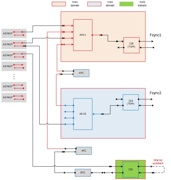
I2S-x and I2S-y Under Same Clock Domain
If I2S-x and I2S-y are under the same clock domain for the sake of case study, AFC1 insertion between ADX1-1 and AMX1-4 does not help. However, the audio routing path can still be constructed as follows.
• AMX connection routing commands:
amixer -c 0 sset 'AMX1-1 Mux' 'ADMAIF1'
amixer -c 0 sset 'AMX1-2 Mux' 'AFC1'
amixer -c 0 sset 'AMX1-3 Mux' 'ADMAIF2'
amixer -c 0 sset 'AMX1-4 Mux' 'AFC2'
amixer -c 0 sset 'I2S4 Mux' 'AMX1'
• ADX connection routing commands:
amixer -c 0 sset ‘ADX2 Mux' 'I2S3'
amixer -c 0 sset 'ADMAIF2 Mux' 'ADX2-4'
amixer -c 0 sset 'AFC1 Mux' 'ADX2-1'
• AFC/SFC connection routing commands:
amixer -c 0 sset 'SFC1 Mux' 'I2S5'
amixer -c 0 sset 'I2S5 Mux' 'ADMAIF3'
amixer -c 0 sset 'AFC2 Mux' 'SFC1'
amixer -c 0 cset iface=MIXER,name='output rate' '48kHz'
amixer -c 0 sset 'I2S5 Loopback' 1
• Testing commands:
aplay -c 0 -D hw:0,0 -f S16_LE -r 48000 sample1.wav&
aplay -c 0 -D hw:0,1 -f S16_LE -r 48000 sample2.wav&
aplay -c 0 -D hw:0,2 -f S16_LE -r 48000 sample3.wav&
arecord -c 0 -D hw:0,1 -f wav -c 2 -r 48000 -b 16 sample4.wav &