Sensor Driver Programming Guide
This topic provides advanced information for developing USB cameras and Bayer and YUV image sensor with NVIDIA® Tegra® Board Support Package (BSP) releases.
Additionally, guidance is provided for the implementation of drivers suitable for use with this release. Implementation of a camera sensor driver enables acquisition of camera data over the CSI bus, in the native format, provided by the sensor. It is intended for use in enabling sensors that contain an ISP such as YUV output.
The Binary Support Package (BSP) supports two types of camera programming paths, depending on the camera and the application.
• Scalable Camera Framework
• Direct V4L2 Interface
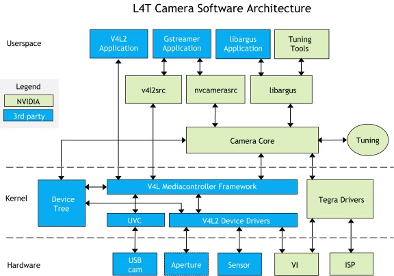
Scalable Camera Framework
The Scalable Camera Framework (SCF) user mode library provides all the controls and data processing between the application and kernel-mode V4L2 drivers. In applications that use the Tegra ISP functionality, use the Scalable Camera Framework. Typically, for Bayer sensors, applications use the SCF library to convert RGB format to YUV format and to do various post processing tasks.
The architecture framework with the application and kernel mode V4L2 drivers is as follows:
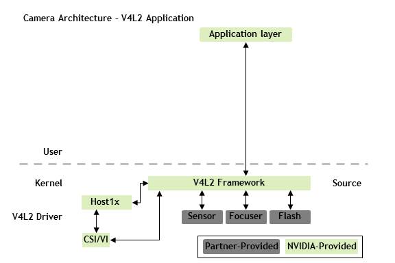
Direct V4L2 Interface
In applications that support a direct V4L2 interface, use this interface to communicate to the NVIDIA V4L2 driver without having to use the SCF library. Use this path for a YUV sensor since this sensor has a built-in ISP and frame does not need extra processing.
The application uses the kernel mode V4L2 drivers as follows:
This topic describes how to bring up a Bayer sensor with the Tegra BSP. Bringing up the sensor requires customers to develop:
• Device Tree in the Linux kernel
• V4L2 sensor driver
The provided examples use OmniVision OV5693 sensor, and the source code for OV5693 sensor is available.
Camera Modules
A camera module installed on the target platform can consist of one or more devices. A typical rear camera module includes a complementary metal-oxide semiconductor (CMOS) sensor, combined with a Voice Coil Motor (VCM) focuser. A typical front camera module may include a single CMOS sensor.
To add one or more camera modules to a device tree
1. Locate or create a tegra-camera-platform device node in the kernel source tree at:
• TX1:
hardware/nvidia/platform/t210/jetson/kernel-dts/jetson-platforms/
• TX2:
hardware/nvidia/platform/t18x/common/kernel-dts/t18x-common-modules
2. In a Tegra-camera-platform device node, create a module table (modules) with one or more modules.
Each module must contain its basic information and the definition of the devices that are inside that module.
Note: | All value fields in camera-related device nodes must use the string data type, except for the files that refer to other device nodes. |
A typical device-tree node for a camera module is as follows:
tegra-camera-platform {
compatible = "nvidia, tegra-camera-platform";
modules {
module0 {
badge = "e3326_front_P5V27C";
position = "rear";
orientation = "1";
drivernode0 {
pcl_id = "v4l2_sensor";
proc-device-tree = "/proc/device-tree/i2c@3180000/ov5693_c@36";
};
drivernode1 {
pcl_id = "v4l2_focuser_stub";
};
};
};
};
Module Properties
The information for moduleX: module (or moduleX: modules) is as follows:
Property | Value |
badge | A unique name that identifies this module. Guidelines for naming the three parts of the badge_info property: • The first part is the camera board ID (camera_board_id) of the module. • The second part contains the position of the module, for example, rear or front. • The third part contains the last six characters of a part number, which you can find in the data sheet on the module from the vendor. If your system has multiple modules that are identical, create a unique name for each module. For example, if you have one module for a rear facing camera and an identical module for a front facing camera, you can call the rear camera module e3326_rear_P5V27C and the front camera module e3326_front_P5V27C. |
position | The camera-facing information. The positions supported depends on the number of cameras in the system: • Two-camera system: rear and front. • Three-camera system: bottom, top, and center. • Six-camera system: bottomleft, bottomright, centerleft, centerright, topleft, and topright. |
orientation | The orientation related to the display panel. If there is no display panel, just label each camera with 0-based index. • Rear facing: 0 • Front facing: 1 |
drivernodeX | The information on the driver node; X: 0-based index. |
Driver Properties
The information for drivernodeX: device (or drivernodeX: devices) is as follows:
Property | Value |
pcl_id | A unique name that identifies this device. |
Individual Imaging Device
An imaging device is a component inside the camera module. It can be a:
• Sensor
• Focuser
• Flash
You must add all the required information to the device-tree node to support the device operation.
For each device-tree node for a device, assign a device node that contains:
• The name of the device
• The slave address for the device
• A compatible string that identifies the node
Note: | Except for devices that refer to other device nodes, all value fields in camera-related device nodes must use the string data type. |
An example device-tree node for the OV5693 V4L2 sensor driver is as follows:
ov5693_c@36 {
compatible = "nvidia,ov5693";
reg = <0x36>;
devnode = "video2";
physical_w = "3.674";
physical_h = "2.738";
sensor_model = "ov5693";
avdd-reg = "vana";
iovdd-reg = "vif";
mode0 { // OV5693_MODE_2592X1944
mclk_khz = "24000";
num_lanes = "2";
tegra_sinterface = "serial_c";
discontinuous_clk = "no";
dpcm_enable = "false";
cil_settletime = "0";
active_w = "2592";
active_h = "1944";
pixel_t = "bayer_bggr";
readout_orientation = "90";
line_length = "2688";
inherent_gain = "1";
mclk_multiplier = "6.67";
pix_clk_hz = "160000000";
min_gain_val = "1.0";
max_gain_val = "16";
min_hdr_ratio = "1";
max_hdr_ratio = "64";
min_framerate = "1.816577";
max_framerate = "30";
min_exp_time = "34";
max_exp_time = "550385";
Embedded_metadata_height = “0”;
};
...
};
Device Properties
For the device tree node for the V4L2 sensor-device, define the required hardware resource for the device, as follows:
Property | Value |
compatible | Specifies the device identifier. The Linux kernel uses this keyword to bind the device driver to a specific device. |
reg | Specifies the I2C slave address. |
mclk | Specifies the name of the input clock for the device. Note: CAM1_MCLK (GPIO_PS0) and CAM2_MCLK (GPIO_PS1) are both from extperiph3_clk, of which clk name must be cam_mclk1 (or mclk3). |
XXX-gpio | Specifies the general-purpose input/output (GPIO) pins for the device, where XXX is the GPIO pin for the camera. There are four default gpio pins for camera: • S4 - Camera0 Reset • S7 - Camera0 Power Down • S5 - Camera1 Reset • T0 - Camera1 Power Down |
XXX-supply | Specifies the regulator for the device, where XXX is the actual regulator name defined somewhere else in the device tree. The -supply suffix is mandatory. The following are the defined regulators: • vana-supply = <&en_vdd_cam_hv_2v8>; // analog 2.8v • vdig-supply = <&en-vdd-cam_1v2>; // digital 1.2v • vif-supply = <&en-vdd-cam>; // interface 1.8v • vvcm-supply = <&en_vdd_vcm_2v8>; // analog 2.8v for vcm |
XXX-reg | Specifies the name of the regulator, where XXX is the regulator name for the sensor driver. The value of this field is the regulator name with the suffix -reg. The following are the defined regulators: • avdd-reg = “vana”; • dvdd-reg = “vdig” • iovdd-reg = “vif” • vcmvdd-reg = “vvcm” |
physical_w | Specifies the physical width (in millimeters) of the sensor. |
physical_h | Specifies the physical height (in millimeters) of the sensor. |
sensor_model | Specifies which sensor is in this module |
devnode | Specifies a value used to derive the kernel device node. /dev/<devnode> |
post_crop_frame_drop | Specifies number of frames to be dropped after applying sensor crop settings. |
use_decibel_gain | When set to true, analog gain value received by driver is expressed in decibels. dB = 20 * log(Analog Gain) |
Property-Value Pairs
The property-value pairs that apply to the sensor mode for the V4L2 implementation are as follows:
Property | Value |
modeX | Specifies the sensor-mode information, that is, the X: 0-based index. |
ports | Specifies the media controller graph binding information. |
mclk_khz | Specifies the standard MIPI driving clock, which is typically 24MHz. |
num_lanes | Specifies the number of lane channels the sensor is programmed to output. |
tegra_sinterface | Specifies the base Tegra serial interface to which the lanes are connected. |
discontinuous_clk | Specifies the indication that the sensor is programmed to use a discontinuous clock on MIPI lanes. |
cil_settletime | Specifies the value of the settle time of the MIPI lane. A 0 value attempts to auto-calibrate according to the mclk_multiplier parameter. |
dpcm_enable | Specifies whether to enable dpcm compression for this mode. Set to true or false. |
active_h | Specifies the height of the pixel-active region. |
pixel_t | Specifies the readout pixel pattern of the sensor. The following examples shows the values for Bayer sensors with the “bggr” pixel pattern: • 10 bit: bayer_bggr • 12 bit: bayer_bggr12 • 14 bit: bayer_bggr14 |
readout_orientation | For Android only: Specifies the readout orientation that is based on the orientation of the camera module. Change this property if you would like to program a different readout order for this mode. Possible values: • 0 • 90 • 180 • 270 |
line_length | Specifies the pixel line length (width) for sensor mode for calibrating the features in our camera stack. This value must be equal or larger than active_w. |
mclk_multiplier | Specifies the multiplier to MCLK for timing the capture sequence of the hardware. Use the following equation to calculate this value: mclk_multiplier = desired ISP clock frequency / mclk. This value must be larger than pixel_clk_hz / mclk to prevent ISP underrun. |
pix_clk_hz | Specifies the sensor pixel clock for calculating the exposure, frame rate, and so forth. This value is calculated based on input clock (mclk) and PLL settings from sensor mode table. Please refer to sensor data sheet for how to calculate this value. |
inherent_gain | Specifies the gain obtained inherently from the mode, that is, pixel binning. Set to 1 if you do not know this value. |
min_gain_val | Specifies the minimum gain limit for the mode. |
max_gain_val | Specifies the maximum gain limit for the mode. This can be increased to include digital gain, if that is supported by the sensor. |
min_exp_time | Specifies the minimum exposure time limit for the mode in microseconds. |
max_exp_time | Specifies the maximum exposure time limit for the mode in microseconds. |
min_hdr_ratio | Specifies the minimum high-dynamic-range (HDR) ratio limit for the mode (for interleave HDR sensors). For non-HDR sensors, set min_hdr_ratio to an empty string. |
max_hdr_ratio | Specifies the maximum HDR ratio limit for the mode (for HDR sensors). |
min_framerate | Specifies the minimum frame-rate limit for the mode in frames per second (fps). Use the following equation to calculate this value: min_framerate = pix_clk_hz / (line_length * maximum frame length) |
max_framerate | Specifies the maximum frame-rate limit for the mode in fps. Use the following equation to calculate this value: max_framerate = pix_clk_hz / (line_length * minimum frame length) |
embedded_metadata_height | Specifies how many extra embedded metadata rows for each frame. Set to 0 to disable embedded metadata support. |
Example Focuser Driver Properties
The required information for an LC898212 focuser driver is as follows:
lc898212@72 {
compatible = "nvidia,lc898212";
reg = <0x72>;
devnode = "video6";
type = "default";
ports {
#address-cells = <1>;
#size-cells = <0>;
port@0 {
reg = <0>;
lc898212_out0: endpoint {
remote-endpoint = <&vi_in1>;
};
};
};
};
The focuser driver properties are as follows:
Property | Value |
compatible | Specifies the device identifier. |
reg | Specifies the I2C slave address. |
type | Specifies the focuser type: • default: VCM focuser. • steppermotor: Stepper motor focuser. |
ports | Media controller graph binding info. |
V4L2 Kernel Driver
This topic is based on the Video for Linux 2 (V4L2) driver for the OmniVision OV5693 sensor (ov5693.c) at:
kernel/kernel-4.4/drivers/media/i2c/ov5693.c
Examine this source content to obtain a complete understanding of the driver.
Note: | The V4L2 sensor driver MUST be built-in the kernel, not compiled as a loadable module. |
Macro Definitions
The sensor-specific macro values include:
• The minimum and maximum values for each control.
• The default value for each control.
• The macro values required for sensor timing or general functionality.
Sensor-Private Data
The structure contains the private data specific to the sensor:
struct ov5693 {
struct camera_common_power_rail power;
int numctrls;
struct v4l2_ctrl_handler ctrl_handler;
struct camera_common_eeprom_data eeprom[OV5693_EEPROM_NUM_BLOCKS];
u8 eeprom_buf[OV5693_EEPROM_SIZE];
struct i2c_client *i2c_client;
struct v4l2_subdev *subdev;
struct media_pad pad;
s32 group_hold_prev;
bool group_hold_en;
struct regmap *regmap;
struct camera_common_data *s_data;
struct camera_common_pdata *pdata;
struct v4l2_ctrl *ctrls[];
};
The sensor properties are as follows:
Property | Value |
power | Holds generic power controls, include regulators, clks, and GPIOs. |
numctrls | Holds the number of v4l2 controls for the sensor. |
ctrl_handlerr | Holds the required v4l2 handler to controls, needed for v4l2 control init. |
i2c_client | Holds a handle to i2c_client, used to access to sensor i2c client instance. |
subdev | Holds a handle for v4l2 sub-device, needed to run subdev operations (ops). |
eeprom | Holds common EEPROM device data. |
eeprom_buf | Holds EEPROM buffer storage. |
pad | Holds media pad used for media controller initialization for a device to work as SINK or SOURCE. |
group_hold_prev | Holds previous state use by group hold control handler to check for change of state. |
group_hold_en | Holds group hold enable flag directly related to group hold control. |
reg_map | Holds a register map setup for I2C read and write. |
s_data | Holds a handle to common data, see documentation for camera_common_data. |
pdata | Holds a handle to common platform data, populated by read Device Tree. |
ctrls | Holds handles to initialized v4l2 controls, dynamic array, MUST BE LAST FIELD. |
Configuring Regmap
Depending on the I2C interface of the sensor, you must update the values of reg_bits and val_bits.
regmap_config {
reg_bits = 16;
val_bits = 8;
};
The regmap_config properties are as follows:
Property | Value |
reg_bits | Specifies the number of bits needed to represent the I2C register offset. |
val_bits | Specifies the number of bits in the buffer to store data to be transferred over I2C. |
Check the vendor register programming table of your sensor to determine the size of reg_bits and val_bits.
Configuring Controls
The controls must be linked to the control handlers.
To link the controls to their control handlers
• Set up the function pointers as follows:
• Point g_volatile_ctrl to the internal get volatile control handler of the sensor.
• Point s_ctrl to the internal set control handler of the sensor.
static const struct v4l2_ctrl_ops ov5693_ctrl_ops = {
.g_volatile_ctrl = ov5693_g_volatile_ctrl,
.s_ctrl = ov5693_s_ctrl,
};
The following code example lists the controls and their initialized values. This list is looped through during the ctrls_init call to initialize each of the controls. Each control is then accessible through the ctrls handler in the private data. The set of controls defined for OV5693 are the standard ones used by the user-mode PCL V4L2 driver.
Note: | Additional controls require a change in the PCL user mode driver. |
Three types of controls are defined for the OV5693 sensor.
static struct v4l2_ctrl_config ctrl_config_list[] = {
/* Integer Control: setting integer values such as gain, coarse
* time, *and frame length.
*/
{
.ops = &ov5693_ctrl_ops, //pointer to control ops
//function
.id = V4L2_CID_GAIN, //id, defined in
//camera_common.h
.name = "Gain", //string name of control
.type = V4L2_CTRL_TYPE_INTEGER, //type of control
.flags = V4L2_CTRL_FLAG_SLIDER, //control flags
// The following three are the value most likely
// needs changing
.min = OV5693_MIN_GAIN, //control value lower bound
.max = OV5693_MAX_GAIN, //control value upper bound
.def = OV5693_DEFAULT_GAIN, //default control value
.step = 1, //increment step size for
//value
},
...
/* String Data Control: converts data to string format then
* send to PCL user mode
* drivers, used for EEPROM, OTP, and fuse id.
*/
{
.ops = &ov5693_ctrl_ops,
.id = V4L2_CID_EEPROM_DATA,
.name = "EEPROM Data",
.type = V4L2_CTRL_TYPE_STRING,
.flags = V4L2_CTRL_FLAG_VOLATILE,
.min = 0,
/* the following one is the value that likely needs
* changing, the string size is 2 times actual
* buffer size
*/
.max = OV5693_EEPROM_STR_SIZE,
.step = 2,
},
...
/* Menu Control: used as on/off switch for group hold and HDR.
* switch_ctrl_qmenu is used to define the states on/off there
* shouldn't be a need to change these controls, unless a
* completely new one is being added.
*/
{
.ops = &ov5693_ctrl_ops,
.id = V4L2_CID_GROUP_HOLD,
.name = "Group Hold",
.type = V4L2_CTRL_TYPE_INTEGER_MENU,
.min = 0,
.max = ARRAY_SIZE(switch_ctrl_qmenu) - 1,
.menu_skip_mask = 0,
.def = 0,
.qmenu_int = switch_ctrl_qmenu,
},
};
Setting Up Control Registers
Set up register writes for integer controls with the following functions:
• addr depends on the sensor being used.
• val is the source from the control handler.
Each control handler calls these functions to set up register writes for each of the controls.
ov5693_get_frame_length_regs
ov5693_get_coarse_time_regs
ov5693_get_coarse_time_short_regs
ov5693_get_gain_reg
ov5693_get_gain_short_reg
Read-Write Wrapper in the Register
The following functions are wrappers for the read-write interface of the I2C register. For OV5693, use the regmap interface. However, you can modify these functions for other interfaces.
ov5693_read_reg
ov5693_write_reg
ov5693_write_table
Power Functions
The functions for power-related controls are as follows:
Function | Description |
ov5693_power_on | Contains the power-on sequence. You must modify this function according to the specification sheets. Calls regulator_enable() to turn on regulators and use gpio_set_value() to toggle the GPIO pins. |
ov5693_power_off | Contains the power-off sequence. You must modify this function according to the specification sheets. Calls regulator_enable() to turn on regulators and use gpio_set_value() to toggle the GPIO pins. |
ov5693_power_put | Calls regulator_put () on all regulators. |
ov5693_power_get | Calls camera_common_regulator_get() helper function or regulator_get() to acquire all regulators. |
Setting Up V4L2 Subdevice and Camera Common
The
ov5693_s_stream function is mainly for writing mode tables by making calls to register the
write_table function. You set up mode tables in the
ov5693_mode_tbls.h file. For details, see
Mode Tables.
In addition to writing mode tables and enabling the stream through stream-enable register writes,
ov5693_s_stream also writes the initial integer-control values to the register through direct calls to the integer-control handlers. For details, see the section
Control Handlers.
control.id = V4L2_CID_GAIN;
err = v4l2_g_ctrl(&priv->ctrl_handler, &control);
err |= ov5693_set_gain(priv, control.value);
……
If a test pattern is supported by the sensor, and you can create a register table for that pattern, you can add a test_mode flag to write the test-mode table.
Camera common is a set of functions that are common to camera drivers of the NVIDIA kernel, to which this driver refers. Camera common sets up most of the V4L2 framework, requiring linkage from the driver as follows:
struct camera_common_sensor_ops
struct camera_common_data
For details on modifying and adding new modes, see
Mode Tables.
The following code snippets set up the V4L2 subdevices and camera common for registering the sensor driver with the V4L2 framework. The s_stream pointer must point to the internal s_stream function of the sensor; you can leave the other pointers as is.
static struct v4l2_subdev_video_ops ov5693_subdev_video_ops = {
.s_stream = ov5693_s_stream,
...
};
You do NOT need to modify this structure:
static struct v4l2_subdev_core_ops ov5693_subdev_core_ops = {
...
};
Match the name for the pointer for the core and video operations function with the two from above, as follows:
static struct v4l2_subdev_ops ov5693_subdev_ops = {
.core = &ov5693_subdev_core_ops,
.video = &ov5693_subdev_video_ops,
};
During the parsing of the device tree, of_device_id matches the compatible field with the one in the Device Tree.
static struct of_device_id ov5693_of_match[] = {
{ .compatible = "nvidia,ov5693", },
{ },
};
This structure is required for camera common and you must set up the function pointers appropriately. Link the power_on, power_off, write_reg, and read_reg functions here:
static struct camera_common_sensor_ops ov5693_common_ops = {
.power_on = ov5693_power_on,
.power_off = ov5693_power_off,
.write_reg = ov5693_write_reg,
.read_reg = ov5693_read_reg,
};
Control Handlers
This topic describes the control handlers that control the top-level structure and tells the function how many controls the handler is expected to handle.
Set Control
The set-control function is used to call the desired control handler.
V4L2 Set-Control Operation
The V4L2 set-control function contains a switch statement to redirect set-control calls to their appropriate control handlers.
Note: | Read-only controls, such as fuse_id and One-Time Programmable Read-Only Memory (OTP ROM), do not have a case statement in the control ID switch statement. |
ov5693_s_ctrl {
...
switch (ctrl->id) {
case V4L2_CID_GAIN:
...
case V4L2_CID_EEPROM_DATA:
...
case V4L2_CID_HDR_EN:
...
}
...
}
Note: | For EEPROM_DATA, the string control must have a pre-allocated string passed in. Hence, a null check is necessary before passing the string to the control handler. |
HDR_EN is a pure software control. No control handler writes to the hardware so simply break out of the switch statement.
Setter-Control Handlers (Writes)
Setter-control handlers are the control handlers called by s_ctrl. They perform additional control-handling operations, such as writes to registers. The majority of these controls make calls to the control register setup functions. The exception is write_eeprom, which acts as a separate I2C device with its own I2C write interface.
ov5693_set_group_hold
ov5693_set_gain
ov5693_set_frame_length
ov5693_set_coarse_time
ov5693_set_coarse_time_short
ov5693_write_eeprom
Note a special case for the gain-control handler, which contains a function call to:
ov5693_calculate_gain(val, OV5693_GAIN_SHIFT);
The function takes a binary-coded decimal from user space as input and computes the gain-register value according to the vendor-provided gain-calculation formula. Because that formula can vary from sensor to sensor, you must rewrite this function in the V4L2 sensor driver for each of the sensors.
The input of this function is the gain value passed in from user space.
• The value is a binary-coded decimal ranging from 1 to 16.
• The binary-coded decimal is divided into a six-byte integer representation and a two-byte decimal representation.
• The most significant six bytes of val is the integer representation.
• The least significant two bytes is the decimal representation, which is actually the numerator of a fraction over the maximum decimal representation of 0xFF.
The output of this function is the actual gain-register value programmed over I2C. That value depends on the gain-calculation formula provided by the sensor vendor. It is usually found in the datasheets for the sensor. The goal of this function is to convert the decimal val input into the gain-register value with as little truncation as possible.
For the OV5693 formula on which the ov5693_calculate_gain (or _to_gain) function is based, see the OV5693 Software Reference Manual.
Exposure/Framerate Controls
Sensor drivers controlling sensor exposure and frame rate must implement V4L2_CID_FRAME_LENGTH and V4L2_CID_COARSE_TIME controls. These controls are used to update sensor frame length and coarse integration time registers with the values calculated from user-mode camera stack.
If the sensor driver has special requirements or direct calculation of the exposure and frame rate is required, V4L2_CID_FRAME_RATE and V4L2_CID_EXPOSURE controls can be implemented instead. When these two controls are implemented, they receive unprocessed frame rate and exposure values in fixed point format. The driver must perform any necessary determination of final register settings.
Note: | The V4L2_CID_FRAME_LENGTH and V4L2_COARSE_TIME controls take 32-bit input parameters and V4L2_CID_FRAME_RATE and V4L2_EXPOSURE take 64-bit input parameters. Use either set of controls but do not mix or use both sets at once. |
Fixed Point Format
When the driver implements V4L2_CID_FRAME_RATE and V4L2_CID_EXPOSURE controls, the received control values are in Q10.22 fixed point format. In Q10.22 fixed point format, the upper 10 bits are for storing integer values and the lower 22 bits are for fraction values. This is a workaround for lacking floating point in the kernel.
This formatting is achieved by multiplying the original value with 1 << 22. For your convenience, a FIXED_POINT_SCALING_FACTOR value is defined as follows:
#define FIXED_POINT_SCALING_FACTOR (1ULL << 22)
Use caution before using these fixed point format values. The value must be divided back to original precision for the calculation. For best results, multiply first, and then divide the value with FIXED_POINT_SCALING_FACTOR last, to avoid unexpected truncation/rounding issues.
Get-Volatile Control
Following are the get-volatile controls:
• V4L2 get-volatile control operation: The ov5693_g_volatile_ctrl function contains a switch statement for redirecting get-control calls to their appropriate control handlers.
Note: | For non-volatile controls, get-control simply returns the previously written value stored in the control handler. |
• Get-control handler (reads): The ov5693_read_eeprom control handler is an example of a get-volatile control handler. This handler reads the volatile value directly from the EEPROM register and updates the value that is read back every time get is called on this control.
Other Control-Related Functions
Following are the other control-related functions:
• EPROM device-related controls: These two functions are for setting up EEPROM as a separate I2C device with its own regmap interface:
ov5693_eeprom_device_init
ov5693_eeprom_device_release
• Handlers called on ctrls_init: These control handlers are called once from the ctrls_init function because OTP and fuse_id controls are read-only and their values are read once during boot time.
For more information, see Boot-Time Initialization.
Boot-Time Initialization
The functions for initializing boot time.
Control Initialization
The ov5693_ctrls_init function iterates through ctrl_config_list and registers each control as a new custom control with the V4L2 framework. s_ctrl is also called for each control to set it to its default value defined in ctrl_config_list.
For more information, see
Configuration Controls.
Modifying this function is necessary if you have calls for initializing the value for the read-only controls. See the calls to
otp_setup and
fuse_id_setup in
Control Handlers.
ov5693_ctrls_init {
...
err = ov5693_otp_setup(priv);
...
err = ov5693_fuse_id_setup(priv);
...
}
Device Tree Parser
The ov5693_parse_dt function, which parses device trees, takes the Device Tree node and looks for the parameters, according to the sensor-related private data, required by the sensor driver.
The values include but are not limited to:
mclk
pwdn-gpios
reset-gpios
af-gpios
avdd-reg
dvdd-reg
iovdd-reg
For details on how to set up device trees with the appropriate values, see the documentation. You must match the name list with the names in the Device Tree for their respective name-value pairs.
Port binding
vi {
num-channels = <1>;
ports {
#address-cells = <1>;
#size-cells = <0>;
port@0 {
reg = <0>;
vi_in0: endpoint {
csi-port = <2>;
bus-width = <2>;
remote-endpoint = <&csi_out0>;
};
};
};
};
nvcsi {
num-channels = <1>;
#address-cells = <1>;
#size-cells = <0>;
channel@0 {
reg = <0>;
ports {
#address-cells = <1>;
#size-cells = <0>;
port@0 {
reg = <0>;
csi_in0: endpoint@0 {
csi-port = <2>;
bus-width = <2>;
remote-endpoint = <&ov5693_out0>;
};
};
port@1 {
reg = <1>;
csi_out0: endpoint@1 {
remote-endpoint = <&vi_in0>;
};
};
};
};
The port binding properties are as follows:
Function | Description |
port | Specifies the mediapad that the port is connected. All imager devices will have only one media pad for binding the connection with VI. |
csi-port | This value defines the CSI port sensor is connected. For imager devices like focuser or flash this field is not required. |
bus-width | Bus width defines the number of CSI lanes connected to sensor. |
remote-endpoint | Remote end point is the label used for binding two ports. The binding expects one port is the sink and the other one is the source. |
Media Controller Setup
A few additional components are needed to setup the media controller for V4L2 use. The open call is a placeholder operation for satisfying the V4L2 sub-device internal operation requirements. The setup likely will not need to be change besides a name changed to match the devices.
ov5693_open
Sub-device function operations must link to the open operation:
static const struct v4l2_subdev_internal_ops ov5693_subdev_internal_ops = {
.open = ov5693_open,
};
Media entity function operations must link to the V4L2 sub-device link validation method:
static const struct media_entity_operations ov5693_media_ops = {
.link_validate = v4l2_subdev_link_validate,
};
Sensor-Driver Probing
The probing function of the sensor driver are as follows.
Entry Point for Initialization During Boot
The
ov5693_probe function is the entry point of the driver. The function starts off by allocating memory for common data and sensor-private data. For more information, see
Sensor-Private Data.
common_data = devm_kzalloc(&client->dev,
sizeof(struct camera_common_data), GFP_KERNEL);
priv = devm_kzalloc(&client->dev,
sizeof(struct ov5693) + sizeof(struct v4l2_ctrl *) *
ARRAY_SIZE(ctrl_config_list),
GFP_KERNEL);
The function then initializes regmap:
priv->regmap = devm_regmap_init_i2c(client, &sensor_regmap_config);
Next, the function calls the other initialization functions, including:
// See the section Parser for Device Trees: stored in private
// data pdata field.
ov5693_parse_dt(client);
ov5693_power_get(priv);
// Link the appropriate subdev ops see
v4l2_i2c_subdev_init(&common_data->subdev, client, &subdev_ops);
ov5693_ctrls_init(priv);
ov5693_eeprom_device_init(priv);
Next, the function links the common data and sensor-private values:
common_data->ops = &ov5693_common_ops;
// Control handler linking
common_data->ctrl_handler = &priv->ctrl_handler;
// I2C client passed in to probe
common_data->i2c_client = client;
common_data->frmfmt = &ov5693_frmfmt[0];
// Based on default data format definition, generally defaults
common_data->colorfmt = camera_common_find_datafmt(
OV5693_DEFAULT_DATAFMT);
// Power-handler linking
common_data->power = &priv->power;
// Sensor-private data linking
common_data->priv = (void *)priv;
common_data->numfmts = ARRAY_SIZE(ov5693_frmfmt);
// Set up of port information for device
camera_common_parse_ports(...)
// Port information is also used to create the name for debugfs node setup
Setup of Default Values for Common Data
For more information, see
Macro Definitions.
common_data->def_mode = OV5693_DEFAULT_MODE;
common_data->def_width = OV5693_DEFAULT_WIDTH;
common_data->def_height = OV5693_DEFAULT_HEIGHT;
common_data->def_clk_freq = OV5693_DEFAULT_CLK_FREQ;
debugfs_name
// I2C client passed in to probe
priv->i2c_client = client;
// Link to common data above
priv->s_data = common_data;
// Link to V4L2 subdevice handler
priv->subdev = &common_data->subdev;
// Link to subdevice dev to i2c_client dev (for media controller usage)
priv->subdev->dev = &client->dev;
// Initialize previous group hold state to 0
priv->group_hold_prev = 0;
Setup of Media Controller
All imager devices must register themselves as sub devices to media controller framework. VI acts as the master device which controls the binding, parsing the DT and establishes the media links once all the sub devices are registered.
Each sub-device can register to media controller framework by defining the entity and pads information.
• Entity: Media entity is the unit device represented by media controller framework for establishing connections. Each media entity can have multiple pads. Framework provides a list of known entity types and the corresponding media operations.
• Pad: Pad represents the device behaves as SINK or SOURCE port. Imager device must have a SOURCE port which is bound to VI. If imager device has a SINK port then the SOURCE port which binds the device SINK port must be represented in DT to complete the binding.
// Link subdevice internal and media entity operations
priv->subdev->internal_ops = &ov5693_subdev_internal_ops;
priv->subdev->entity.ops = &ov5693_media_ops;
// Setup subdevice flags and media entity type
priv->subdev->flags |= V4L2_SUBDEV_FL_HAS_DEVNODE | V4L2_SUBDEV_FL_HAS_EVENTS;
priv->subdev->entity.type = MEDIA_ENT_T_V4L2_SUBDEV_SENSOR;
// Setup media controller pad flags
priv->pad.flags = MEDIA_PAD_FL_SOURCE;
// Initialize and register subdevice and media entity with media controller framework.
media_entity_init(&priv->subdev->entity, 1, &priv->pad, 0);
v4l2_async_register_subdev(priv->subdev);
Removing Sensor Drivers
The ov5693_remove function removes the sensor-device instance and calls on a device shutdown.
This function makes calls to various free, put, and destroy functions that match up with several calls in probe. It must remain largely the same.
// freeing the control handler.
v4l2_ctrl_handler free(&priv->ctrl_handler);
ov5693_power_put(priv);
Device Registration
After driver development is complete, you must add your device information to the system kernel device tree so it can be instantiated when the kernel boots. There are two ways of registering your device.
Using Plugin Manager
If your camera module has onboard EEPROM and has a valid camera ID programmed, Plugin Manager can be used. If your device module does not meet this requirement, use the main platform device tree instead by following the directions in
Using Main Platform Device Tree File.
Plugin Manager automatically links devices when the system kernel boots. Plugin Manager uses the camera module ID returned by the boot loader to update the device tree entries with proper information at runtime. Plugin Manager allows a single system image to support multiple camera devices. To change camera modules, power down the device, replace the camera module, and then reboot. The new module works automatically.
For Plugin Manager support, add your DTSI file to the camera configuration DTSI file, and then update the camera plugin manager DTSI with proper override information.
Prerequisites
• You have obtained the kernel source files. For more information, see Synchronizing the Kernel in Getting Started.
To enable Plugin Manager support
1. Add your device DTSI to the camera lists in:
• TX1:
hardware/nvidia/platform/t210/jetson/kernel-dts/jetson-platforms/tegra210-jetson-cv-camera-modules.dtsi
• TX2:
hardware/nvidia/platform/t18x/common/kernel-dts/t18x-common-platforms/tegra186-quill-camera-modules.dtsi
2. Add the override information to:
• TX1:
hardware/nvidia/platform/t210/jetson/kernel-dts/jetson-plugin-manager/tegra210-jetson-cv-camera-plugin-manager.dtsi
• TX2:
hardware/nvidia/platform/t18x/common/kernel-dts/t18x-common-plugin-manager/tegra186-quill-camera-plugin-manager.dtsi
Using Main Platform Device Tree File
Register your new device by updating main platform DTSI file to include your new device DTSI file. Because Tegra uses Plugin Manager by default, you must first unregister Plugin Manager support, then add your device information to the main device tree DTSI file.
Prerequisites
• You have obtained the kernel source files. For more information, see Synchronizing the Kernel in the Development Guide for the release.
To register a device using main-platform device tree files
1. Locate and edit the following file:
• TX1:
hardware/nvidia/platform/t210/jetson/kernel-dts/tegra210-jetson-cv-base-p25970-2180-a00.dts
• TX2:
hardware/nvidia/platform/t18x/quill/kernel-dts/tegra186-quill-p3310-1000-a00-00-base.dtsi
2. In the DTSI, remove the following line:
• TX1:
#include "jetson-plugin-manager/tegra210-jetson-cv-camera-plugin-manager.dtsi"
• TX2:
#include <t18x-common-plugin-manager/tegra186-quill-camera-plugin-manager.dtsi"
3. Locate and edit the following file:
TX1:
hardware/nvidia/platform/t210/jetson/kernel-dts/tegra210-jetson-cv-base-p2597-2180-a00.dts
TX2:
hardware/nvidia/platform/t18x/quill/kernel-dts/tegra186-quill-p3310-1000-a00-00-base.dts
4. In the DTS file, replace the following line:
• TX1:
#include "jetson-platforms/tegra210-jetson-cv-camera-modules.dtsi"
• TX2:
#include <t18x-common-platforms/tegra186-quill-camera-modules.dtsi>
With an #include statement specifying the DTSI file for your new device.
Note: | Use tegra210-jetson-cv-camera-modules.dtsi or tegra18x-quill-cv-camera-modules.dtsi as a model for generating your DTSI. In your file, change status = disable to status = okay. |
Verifying the V4L2 Sensor Driver
When the driver is complete, run v4l2-compliance and v4l2-ctl to ensure that your driver can capture raw data through the V4L2 interface.
For details on RAW memory format, see the Tegra X2 Technical Reference Manual “Video Input” topic.
To run a v4l2-compliance test
• Enter the command:
v4l2-compliance -d /dev/video0
Specify the device node path with option ‑d.
• If you have a single camera, the device path is /dev/video0.
• If you have multiple cameras, the number after video indicates the index of one of the camera available in the system. The program will use this camera for the test.
To run a v4l2-ctl test
• Enter the command:
v4l2-ctl --set-fmt-video=width=2592,height=1944,pixelformat=RG10 --stream-mmap --stream-count=100 -d /dev/video0
You can use v4l2-ctl to capture RAW data. You must provide appropriate parameter values for the camera driver you are using.
Both v4l2-compliance and v4l2-ctl are available as open source projects. Documentation for these commands is available from LinuxTV at:
Debugging Tips
When the driver is complete, before running any camera applications, you should first check to see if the camera device node(s) got populated correctly in the system.
If the driver is loaded properly, you should see a /dev/<video#> node. The device node is the file I/O interface with which the user-space driver accesses the driver.
Problems might occur in the probing process and require debugging. Typically, problems occur in the clock, GPIO, and regulator setup. See below for a few tips.
Verify that driver name matches the name in the Device Tree
Your device name should be the same in both the Device Tree and your driver. This is how kernel binds the driver to your device.
In Device Tree:
compatible = "nvidia,ov5693";
In driver:
static struct of_device_id ov5693_of_match[] = {
{ .compatible = "nvidia,ov5693", },
{ },
};
…
.driver = {
.name = "ov5693",
.owner = THIS_MODULE,
.of_match_table = of_match_ptr(ov5693_of_match),
},
Verify that all names match the Device Tree
To debug those problems, first verify that the names that are being read through the parse_dt function matches those in the Device Tree.
Verify that the Device-Tree values match the hardware
Ensure that the values assigned to the Device Tree fields match the hardware they describe. Oftentimes, regulator names, GPIO numbers, and clock names are out-of-date in the Device Tree, causing probing to fail.
Verify that functions run to completion
Ensure that the
power_get calls runs to completion. For details, see
Power Functions and
Boot-Time Initialization.
Another common problem that occurs during probe is in control init.
Verify that default values are correctly linked
Verify that default values are all linked correctly in the control configuration. Also, verify that the default macros are updated appropriately with the values in the mode table of the sensor.
If new controls have been added to the control configuration list, on rare occasions, ensure that they contain the appropriate control handlers and default values.
After probing succeeds, problems could still occur with the control setting. A common problem is in the values of the register writes.
Verify that control-register values are correct
Ensure that the control-register setup contains the correct register address and formats according to the mode table and data sheets. For more information, see
Setting Up Control Registers. For gain control, create a new calculate_gain (to_gain) function for calculating the gain value according to the gain formula in the datasheets.
Verify that mode-specific settings are correct
Double-check the mode-specific settings in the Device Tree and update them if necessary. The most common issues that cause sensor timeout are due to the wrong values for the following settings:
• The value for num_lanes must be 1, 2, or 4, depending on your sensor configuration.
• The tegra_sinterface setting must be set to the proper CSI port where the sensor is connected.
• The discontinuous_clk setting specifies for Tegra that the sensor is running in continuous clock mode (free running), or discontinuous clock mode (gated). If unsure, first set this value to “no”.
• Set the mclk_multiplier to equal or larger than pix_clk_hz / mclk to make sure the ISP is running fast enough to process the data from sensor.
Verify that i2c accesses are working properly
Look closely in kernel logs for any i2c errors for the camera sensor. If there is an i2c error, check the power-on function to verify that the sensor power-on sequence is correct. The order of enabling power, clock, GPIO, and timing must comply with sensor specifications.
Mode Tables
The modes tables of the register reside in a separate header file called sensor_mode_tbls.h and are included by the main driver. Those tables can be a list of reg_8 or reg_16 address-value pairs. Mode tables are separated by resolution. For the ov5693 driver, a common mode table also exists, which contains the common register values among all the resolutions.
static ov5693_reg mode_table_common[] = {
...
};
The start and stop stream-register values must be in a separate mode table. When you separate them, delete the start stream-register values at the end of the resolution mode tables.
static ov5693_reg ov5693_start[] = {
{ 0x0100, 0x01 }, /* mode select streaming on */
{ OV5693_TABLE_END, 0x00 }
};
static ov5693_reg ov5693_stop[] = {
{ 0x0100, 0x00 }, /* mode select streaming off */
{ OV5693_TABLE_END, 0x00 }
};
Also, a table for the color bars of the test pattern is used if the test_mode flag is enabled, activating the test-pattern mode of the sensor. That table is required only if test pattern is supported by the sensor.
static ov5693_reg tp_colorbars[] = {
...
};
At the end of the header of the mode tables is an enumeration of all the mode tables, as well as a list that maps the enumeration to table pointers.
enum {
OV5693_MODE_2592X1944,
...
};
static ov5693_reg *mode_table[] = {
[OV5693_MODE_2592X1944] = mode_2592X1944,
...
};
The camera_common_frmfmt array list is a required table that sets up the format for the V4L2 framework. Each of the elements on that list contains the resolutions, the is_hdr flag, and the enumeration for the mode.
static const struct camera_common_frmfmt ov5693_frmfmt[] = {
{{2592, 1944}, 0, OV5693_MODE_2592X1944},
...
};
To add a register mode table
1. Obtain the address-value pairs for the mode table you would like to add.
Note: | If separate stream-on and stream-off mode tables exist, you can omit them from the mode table. |
2. Format the pairs according to the register structure and initialize a static array with the mode resolution as part of the name. For example:
static ov5693_reg mode_####x####[] = {
{ 0x0100, 0x01 }, /* mode select streaming on */
...
/* your addr and val pairs */
};
The mode table is now in place. End the table array with the following:
{ OV5693_TABLE_END, 0x00 }
3. Create a new enumeration in the list of enumerations and add it to the array of mode tables:
enum {
...
OV5693_MODE_####X####,
}
static ov5693_reg *mode_table[] = {
...
[OV5693_MODE_####X####] = mode_####x####,
};
4. Add the new mode to the camera_common frmfmt array:
static const struct camera_common_frmfmt ov5693_frmfmt[] = {
...
{{####, ####}, 0, OV5693_MODE_####X####},
};