Hardware Setup
When developing systems and application software with L4T, you run and test your code on an actual reference platform, such as the NVIDIA® Jetson Nano™ Developer Kit. Your code targets this hardware directly, rather than a software simulator or emulator.
Accordingly, you must acquire and set up your carrier board before using L4T. Consult your board documentation for guidance on setting up and configuring your board. See the sections below for additional notes.
Jetson Developer Kit Module Setup
This section provides additional notes that apply to the Jetson Developer Kit for specific Jetson modules.
Jetson Nano
This section describes hardware setup for NVIDIA® Jetson Nano™ devices.
Carrier Board Preparation
Although the carrier board supports a variety of peripheral devices, start developing on L4T with a board that has the following:
• A USB cable to plug into the board recovery port.
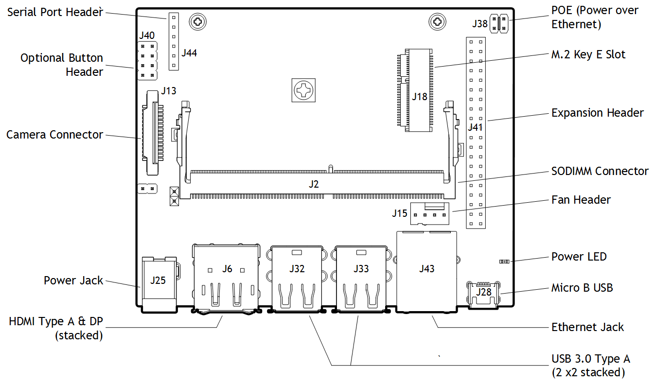
Platform Board Layout
The L4T Jetson Nano board layout and connections are shown in the following diagram.
Jetson AGX Xavier
This section describes hardware setup for NVIDIA® Jetson AGX Xavier™ devices.
Carrier Board Preparation
Although the carrier board supports a variety of peripheral devices, start developing on L4T with a board that has the following:
• A USB‑C cable to plug into the board’s USB‑C flash port.
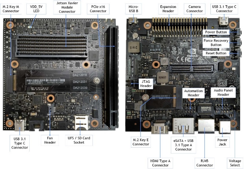
Platform Board Layout
The L4T Jetson AGX Xavier board layout and connections are shown in the following diagram.
Jetson TX2 Series Devices
This section describes hardware setup for NVIDIA® Jetson™ TX2 series devices: Jetson TX2, Jetson TX2i, and Jetson TX2 4GB.
Carrier Board Preparation
Although the carrier board supports a variety of peripheral devices, start developing on L4T with a board that has the following:
• A USB cable to plug into the board recovery port
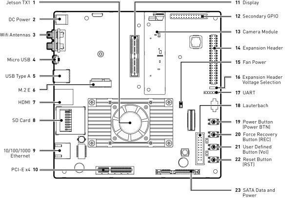
Platform Board Layout
Note: | Jetson TX2 series devices use the same carrier board as NVIDIA® Jetson™ TX1; only the Jetson module differs. Thus the following diagram applies to both Jetson TX2 and Jetson TX1. The “Jetson TX1” label in the diagram itself is not significant. |
Enabling Bluetooth Audio
Applies to: Original Jetson TX2 and Jetson TX2i
To ensure the bluetooth software stack is conformant for the configuration, Bluetooth audio is disabled by default. If additional bluetooth audio profiles are enabled, product conformance may be impacted.
To enable Bluetooth audio
1. For A2DP, run these commands:
sudo apt-get update
sudo apt-get install pulse-audio-module-bluetooth
2. Navigate to the following file:
/etc/systemd/system/bluetooth.target.wants/bluetooth.service
3. Remove A2DP from the noplugin parameter list.
This change allows the A2DP plugin to be loaded and enables the Bluetooth speaker work as expected.
For example, change the following line:
ExecStart=/usr/lib/bluetooth/bluetoothd -d --noplugin=audio,a2dp,avrcp
As follows:
ExecStart=/usr/lib/bluetooth/bluetoothd -d --noplugin=audio,avrcp
4. Reboot the Jetson target device.
5. Pair and use your Bluetooth audio devices.
Jetson TX1
This section describes hardware setup for NVIDIA Jetson TX1 devices.
Carrier Board Preparation
Although the carrier board supports a variety of peripheral devices, start developing on L4T with a board that has:
• A USB cable to plug in to the board recovery port.
Platform Board Layout
The Jetson TX1 carrier board is identical to the Jetson TX2 carrier board, shown in the Jetson TX2 section
Platform Board Layout.
Voltage and Current Monitor
The voltage and current monitor work together with platform hardware to implement a system Electrical Design Point (EDP) management strategy which maximizes CPU and GPU performance within system EDP constraints for the platform.
A voltage comparator and a current monitor detect under-voltage and over-current scenarios. When the sensor outputs are asserted, the Jetson module throttles the CPU and GPU clocks as configured by software to reduce the current load.
The power monitor accepts configuration data from the powermon.dtsi (Device Tree) source file. The following sections give the location of this file, and a code snippet from it, for each platform supported.
Jetson Nano
The Jetson Nano module includes an on-board power monitor, the INA3221, to monitor the voltage and current of the following power rails:
• POM_5V_IN
• POM_5V_CPU
• POM_5V_GPU
The alert outputs of the INA3221 include:
• ALERT
• CRIT
• WARN
The outputs are fed into a SOC_THERM input on the Jetson module. When one or more alert outputs are asserted, the SOC_THERM hardware reacts to reduce module power consumption and avoid violating current limits.
Configuring the Voltage and Current Monitor
The powermon.dtsi file for the Jetson Nano module is located at:
hardware/nvidia/platform/t210/porg/kernel-dts/porg-platforms/tegra210-porg-powermon-p3448-0000-a00.dtsi
The following code snippet is from this file:
i2c@546c0000 {
ina3221x: ina3221x@40 {
compatible = "ti,ina3221x";
reg = <0x40>;
status="okay";
ti,trigger-config = <0x7003>;
ti,continuous-config = <0x7607>;
ti,enable-forced-continuous;
#io-channel-cells = <1>;
#address-cells = <1>;
#size-cells = <0>;
channel@0 {
reg = <0x0>;
ti,rail-name = "POM_5V_GPU";
ti,shunt-resistor-mohm = <5>;
};
channel@1 {
reg = <0x1>;
ti,rail-name = "POM_5V_IN";
ti,shunt-resistor-mohm = <5>;
};
channel@2 {
reg = <0x2>;
ti,rail-name = "POM_5V_CPU";
ti,shunt-resistor-mohm = <5>;
};
};
};
Jetson AGX Xavier
Applies to: NVIDIA® Tegra® Board Support Package (BSP) for the Jetson AGX Xavier module.
The Jetson AGX Xavier module includes an on-board power monitor, the INA3221, to monitor the voltage and current of the following power rails:
• GPU
• CPU
• SOC
• CV
• VDDRQ
• SYS5V
The alert outputs of the INA3221 include:
• ALERT
• CRIT
• WARN
The outputs are fed into a SOC_THERM input on the Jetson module. When one or more alert outputs are asserted, the SOC_THERM hardware reacts to reduce module power consumption and avoid violating current limits.
Configuring the Voltage and Current Monitor
The powermon.dtsi file for the Jetson AGX Xavier module is located at:
hardware/nvidia/platform/t19x/galen/kernel-dts/common/tegra194-powermon-p2888.dtsi
The following code snippet is from this file:
i2c@c240000 {
ina3221x_40: ina3221x@40 {
compatible = "ti,ina3221x";
reg = <0x40>;
ti,trigger-config = <0x7003>;
ti,continuous-config = <0x7c07>;
ti,enable-forced-continuous;
#address-cells = <1>;
#size-cells = <0>;
#io-channel-cells = <1>;
channel@0 {
reg = <0x0>;
ti,rail-name = "GPU";
ti,shunt-resistor-mohm = <5>;
shunt-volt-offset-uv = <&p2888_shuntv_offset>;
};
channel@1 {
reg = <0x1>;
ti,rail-name = "CPU";
ti,shunt-resistor-mohm = <5>;
shunt-volt-offset-uv = <&p2888_shuntv_offset>;
};
channel@2 {
reg = <0x2>;
ti,rail-name = "SOC";
ti,shunt-resistor-mohm = <5>;
shunt-volt-offset-uv = <&p2888_shuntv_offset>;
};
};
ina3221x_41: ina3221x@41 {
compatible = "ti,ina3221x";
reg = <0x41>;
ti,trigger-config = <0x7003>;
ti,continuous-config = <0x7c07>;
ti,enable-forced-continuous;
#address-cells = <1>;
#size-cells = <0>;
#io-channel-cells = <1>;
channel@0 {
reg = <0x0>;
ti,rail-name = "CV";
ti,shunt-resistor-mohm = <5>;
shunt-volt-offset-uv = <&p2888_shuntv_offset>;
};
channel@1 {
reg = <0x1>;
ti,rail-name = "VDDRQ";
ti,shunt-resistor-mohm = <5>;
shunt-volt-offset-uv = <&p2888_shuntv_offset>;
};
channel@2 {
reg = <0x2>;
ti,rail-name = "SYS5V";
ti,shunt-resistor-mohm = <5>;
shunt-volt-offset-uv = <&p2888_shuntv_offset>;
};
};
};
Jetson TX2
Applies to: NVIDIA Tegra Board Support Package (BSP) for the NVIDIA Jetson TX2 and Jetson TX2i modules.
The Jetson TX2 and Jetson TX2i modules each include an on-board power monitor, the INA3221, to monitor the voltage and current of the following power rails:
• VDD_IN
• VDD_CPU
• VDD_GPU
• VDD_SOC
• VDD_SRAM
The alert outputs of the INA3221 include:
• ALERT
• CRIT
• WARN
The outputs are fed into a SOC_THERM input on the Jetson module. When one or more alert outputs are asserted, the SOC_THERM hardware reacts to reduce module power consumption and avoid violating current limits.
Configuring the Voltage and Current Monitor
By default, the Jetson TX2 or Jetson TX2i developer kit’s critical current limit of VDD_IN is set to the maximum possible value of 8190 mA. Therefore, it is not necessary to modify the critical current for lower input voltage unless you want to configure the critical current limit for a specific input voltage.
Jetson TX2 powermon.dtsi File
The powermon.dtsi file for the Jetson TX2 module is located at:
hardware/nvidia/platform/t18x/common/kernel-dts/t18x-common-platforms/tegra186-quill-p3310-1000-a00-powermon.dtsi
The following code snippet is from this file:
i2c@3160000 {
ina3221x_40: ina3221x@40 {
compatible = "ti,ina3221x";
reg = <0x40>;
ti,trigger-config = <0x7003>;
ti,continuous-config = <0x7c07>;
ti,enable-forced-continuous;
#address-cells = <1>;
#size-cells = <0>;
#io-channel-cells = <1>;
channel@0 {
reg = <0x0>;
ti,rail-name = "VDD_SYS_GPU";
ti,shunt-resistor-mohm = <5>;
};
channel@1 {
reg = <0x1>;
ti,rail-name = "VDD_SYS_SOC";
ti,shunt-resistor-mohm = <5>;
};
channel@2 {
reg = <0x2>;
ti,rail-name = "VDD_4V0_WIFI";
ti,shunt-resistor-mohm = <10>;
};
};
ina3221x_41: ina3221x@41 {
compatible = "ti,ina3221x";
reg = <0x41>;
ti,trigger-config = <0x7003>;
ti,continuous-config = <0x7c07>;
ti,enable-forced-continuous;
#address-cells = <1>;
#size-cells = <0>;
#io-channel-cells = <1>;
channel@0 {
reg = <0x0>;
ti,rail-name = "VDD_IN";
ti,shunt-resistor-mohm = <1>;
};
channel@1 {
reg = <0x1>;
ti,rail-name = "VDD_SYS_CPU";
ti,shunt-resistor-mohm = <5>;
};
channel@2 {
reg = <0x2>;
ti,rail-name = "VDD_SYS_SRAM";
ti,shunt-resistor-mohm = <5>;
};
};
};
Jetson TX2i powermon.dtsi File
The e file for the Jetson TX2i module is located at:
hardware/nvidia/platform/t18x/common/kernel-dts/t18x-common-platforms/tegra186-quill-p3489-1000-a00-powermon.dtsi
The following code snippet is from this file:
i2c@3160000 {
ina3221x_40: ina3221x@40 {
compatible = "ti,ina3221x";
reg = <0x40>;
ti,trigger-config = <0x7003>;
ti,continuous-config = <0x7c07>;
ti,enable-forced-continuous;
#address-cells = <1>;
#size-cells = <0>;
channel@0 {
reg = <0x0>;
ti,rail-name = "VDD_SYS_GPU";
ti,shunt-resistor-mohm = <5>;
};
channel@1 {
reg = <0x1>;
ti,rail-name = "VDD_SYS_SOC";
ti,shunt-resistor-mohm = <5>;
};
};
ina3221x_41: ina3221x@41 {
compatible = "ti,ina3221x";
reg = <0x41>;
ti,trigger-config = <0x7003>;
ti,continuous-config = <0x7c07>;
ti,enable-forced-continuous;
#address-cells = <1>;
#size-cells = <0>;
channel@0 {
reg = <0x0>;
ti,rail-name = "VDD_IN";
ti,shunt-resistor-mohm = <1>;
};
channel@1 {
reg = <0x1>;
ti,rail-name = "VDD_SYS_CPU";
ti,shunt-resistor-mohm = <5>;
};
channel@2 {
reg = <0x2>;
ti,rail-name = "VDD_SYS_SRAM";
ti,shunt-resistor-mohm = <5>;
};
};
};
Jetson TX1
Applies to: Jetson TX1
Jetson TX1 modules have an on-board power monitor, the INA3221, to monitor the voltage and current of the following power rails:
• VDD_IN
• VDD_CPU
• VDD_GPU
• VDD_MUX
• VDD_5V_IO_SYS
• VDD_3V3_SYS
• VDD_3V3_IO_SLP
• VDD_1V8_IO
• VDD_3V3_SYS_M2
The alert outputs of the INA3221 include:
• ALERT
• CRIT
• WARN
The outputs are fed into a SOC_THERM input on the Jetson module. When one or more alert outputs are asserted, the SOC_THERM hardware responds by reducing module power consumption to avoid violating current limits.
Configuring the Voltage and Current Monitor
The base powermon .dtsi file for the Jetson TX1 module is located at:
hardware/nvidia/platform/t210/jetson/kernel-dts/jetson-platforms/tegra210-jetson-cv-powermon-p2597.dtsi
This file contains settings for INA channels 1 and 2.
The following code snippet is from this file:
/ {
i2c@7000c400 {
ina3221x@42 {
compatible = "ti,ina3221x";
reg = <0x42>;
ti,trigger-config = <0x7003>;
ti,continuous-config = <0x7607>;
ti,enable-forced-continuous;
#io-channel-cells = <1>;
#address-cells = <1>;
#size-cells = <0>;
status = "okay";
channel@0 {
reg = <0x0>;
ti,rail-name = "VDD_MUX";
ti,shunt-resistor-mohm = <20>;
};
channel@1 {
reg = <0x1>;
ti,rail-name ="VDD_5V_IO_SYS";
ti,shunt-resistor-mohm = <5>;
};
channel@2 {
reg = <0x2>;
ti,rail-name = "VDD_3V3_SYS";
ti,shunt-resistor-mohm = <10>;
};
};
ina3221x@43 {
compatible = "ti,ina3221x";
reg = <0x43>;
ti,trigger-config = <0x7003>;
ti,continuous-config = <0x7607>;
ti,enable-forced-continuous;
#io-channel-cells = <1>;
#address-cells = <1>;
#size-cells = <0>;
status = "okay";
channel@0 {
reg = <0x0>;
ti,rail-name = "VDD_3V3_IO";
ti,shunt-resistor-mohm = <10>;
};
channel@1 {
reg = <0x1>;
ti,rail-name = "VDD_1V8_IO";
ti,shunt-resistor-mohm = <10>;
};
channel@2 {
reg = <0x2>;
ti,rail-name = "VDD_M2_IN";
ti,shunt-resistor-mohm = <10>;
};
};
};
};
The plugin manager powermon.dtsi file for the Jetson TX1 module is located at:
hardware/nvidia/platform/t210/jetson/kernel-dts/jetson-platforms/tegra210-jetson-cv-powermon-p2180-1000-a00.dtsi
Note: | This file contains settings for INA channel 0. |
The following code snippet is from this file:
i2c@7000c400 {
ina3221x: ina3221x@40 {
compatible = "ti,ina3221x";
reg = <0x40>;
ti,trigger-config = <0x7003>;
ti,continuous-config = <0x7607>;
ti,enable-forced-continuous;
#io-channel-cells = <1>;
#address-cells = <1>;
#size-cells = <0>;
status = "disabled";
channel@0 {
reg = <0x0>;
ti,rail-name = "VDD_IN";
ti,shunt-resistor-mohm = <20>;
ti,power-critical-limit-mw = <40000>;
shunt-volt-offset-uv = <&p2180_shuntv_offset>;
};
channel@1 {
reg = <0x1>;
ti,rail-name = "VDD_GPU";
ti,shunt-resistor-mohm = <10>;
shunt-volt-offset-uv = <&p2180_shuntv_offset>;
};
channel@2 {
reg = <0x2>;
ti,rail-name = "VDD_CPU";
ti,shunt-resistor-mohm = <10>;
shunt-volt-offset-uv = <&p2180_shuntv_offset>;
};
};
};