This topic is for software developers whose target is the NVIDIA® Jetson Nano™ module. It describes how to port NVIDIA® Jetson™ Linux Driver Package (L4T) and the U-Boot boot loader from NVIDIA® Jetson Nano™ Developer Kit to other hardware platforms.
For all of the procedures in this topic, the L4T release includes code for the Jetson Nano Developer Kit (P3450) that can serve as an example.
Board Configuration
The Jetson Nano Developer Kit consists of a P3448 System on Module (SOM) attached to a P3449 carrier board. Part number P3450 designates the complete Jetson Nano Developer Kit. The SOM and carrier board each has an EEPROM where the board ID is saved.
The SOM sold for incorporation into customer products is designated P3448-00021. It differs from the SOM included with the developer kit, which is designated P3448-0000. It offers 16GB eMMC storage instead of a micro SD card slot, has a five-year operating lifetime, and is qualified for deployment in a commercial environment. P3448-0002 can be used with the P3449 carrier board.2
Before you use a P3448 SOM with a carrier board other than P3449, change the kernel device tree, bootloader configuration, ODM data, and flashing configuration to configure for the new carrier board instead of P3449. An EEPROM ID for your custom board is not required.
Board Naming
To support a Jetson Nano module with your carrier board, you must assign the module/carrier board combination a lower case alphanumeric name. The name may include hyphens (-) and underscores (_), but not spaces. Following are some examples of valid board names:
p3450
devboard
The name you choose will appear in file names and path names in U-Boot and Linux kernel source code and in user-visible device tree file names, and will be exposed to the user via the U-Boot command prompt and various Linux kernel /proc files.
You must also choose a similarly constructed vendor name. The same character set rules apply, as in this example:
nvidia
In this topic:
• <board> represents your board name.
• <vendor> represents your vendor name.
Note:
Do not simply re-use and modify the existing Jetson Nano Developer Kit code without choosing and using your own board name. If you do not use your own board name it will not be obvious to Jetson Nano users whether modified source code supports your board or the original Jetson Nano Developer Kit carrier board.
Placeholders in the Porting Instructions
The sections below refer to filenames and pathnames that contain the following placeholders. Substitute an appropriate value for each placeholder when you enter the commands.
• <function> is a functional module name, such as power-tree, pinmux, sdmmc-drv, keys, comm (Wi‑Fi/Bluetooth®), camera, etc.
• <board> is a name you have chosen to represent your carrier board with Jetson Nano module. For example, p3450 could represent the carrier board from a Jetson Nano Developer Kit with a Jetson Nano module. Note that NVIDIA <board> names use lower case letters only.
• <som> is a System on a Module (SOM) board name, such as p3448.
• <version> is a board version number, such as a00. Files for NVIDIA reference boards include a version number. Files for customer platforms need not include one.
• <vendor> is your organization’s name, or the name of your board’s vendor.
• <root> is the device that holds the platform’s root file system. At present the only supported value is emmc/sdcard.
Root Filesystem Configuration
Jetson Linux can use any standard or customized Linux root filesystem (rootfs) that is appropriate for their targeted embedded applications.
However, certain settings must be configured in the rootfs’s boot-up framework to set the default configuration after boot, or some of the core functionalities will not run as expected. The configuration file’s pathname is /boot/extlinux/extlinux.conf.
Kernel command line parameters are passed from /boot/extlinux.conf.
For example:
1. The system must be configured to execute the nv.sh, nvfb-early.sh, and nvfb.sh scripts in etc at boot-up because they perform some basic default board initialization in the kernel. It is advisable to add to the etc folder but never delete anything from it.
2. The Xorg and X libraries must be correctly configured for the target device.
3. In the target device’s nvpmodel, the number of cores, clock, and frequency must be configured.
These rootfs configurations and customizations are provided in this driver package in the directory and its subdirectories:
Linux_for_Tegra/nv_tegra/
You must incorporate the relevant customization for your target rootfs from this location.
Note:
For the sample Ubuntu root filesystem provided by NVIDIA, this customization is applied using the script Linux_for_Tegra/apply_binaries.sh.
Pinmux Changes
If your board schematic differs from that for Jetson Nano Developer Kit carrier board, you must change the pinmux configuration applied by the software.
To define your board’s pinmux configuration, you must download the Jetson Nano pinmux table from the Jetson Download Center and customize it for the configuration of your board using the following procedures. Be sure to get the right version of the table for your SOM.
To customize the pinmux spreadsheet
1. Create a copy of the file with a name based on your board name, e.g. <board>_pinmux.xlsm. Note the directory in which you stored the copy; you will need it in the procedure Updating the Bootloader Pinmux.
2. Ensure that the new file is writable.
3. On a Windows PC, open the new file in Microsoft Excel.
4. If Microsoft Excel displays any warnings such as “PROTECTED VIEW” or “SECURITY WARNING,” click Enable Editing or Enable Content, so that you can save your changes to the new file.
5. Rename the Jetson Nano Configuration tab based on the name of your board:
1. Right click the Jetson Nano Configuration tab at the bottom of the window.
2. Click the Rename menu option.
3. Type your board name into the tab, then press ENTER.
6. Modify the spreadsheet columns grouped under the heading “Filled in by Customers” as required from the pinmux configuration for your board, based on the schematic.
7. Once the spreadsheet reflects the configuration you want, click the Generate DT File button to run a macro that exports the configuration data to a pair of .dtsi files in the directory where the spreadsheet is stored. The macro prompts you to enter a prefix for the files’ names; enter jetson_nano_module (the default).
Updating the Bootloader Pinmux
The CBoot bootloader uses device tree files generated from the pinmux spreadsheet to configure the pinmux.
The pinmux settings in device tree files are only applied by CBoot, and not reapplied by the Linux kernel.
To use the updated device tree files, you must rebuild the device tree image for Jetson Nano.
3. Determine the Jetson Nano device tree version and Jetson Nano module variant. You can determine the version and variant from the device tree source file name, which can be found by executing this command on Jetson Nano:
$ cat /proc/device-tree/nvidia,dtsfilename
If the file name is:
• tegra210-p3448-0000-p3449-0000-a02.dts, the version is a02 and the module variant is SKU 0000 (uses SD card memory).
• tegra210-p3448-0002-p3449-0000-a02.dts, the version is a02 and the module variant is SKU 0002 (uses eMMC memory).
• tegra210-p3448-0000-p3449-0000-b00.dts, the version is b00 and the module variant is SKU 0000 (uses SD card memory).
• tegra210-p3448-0002-p3449-0000-b00.dts, the version is b00 and the module variant is SKU 0002 (uses eMMC memory).
4. Locate the directory that contains the pinmux spreadsheet that you modified in To customize the pinmux spreadsheet. Remember that this pathname is on the Windows host, which must be accessible to Linux through the network.
5. Copy the generated .dtsi files from the directory that contains the spreadsheet to the following locations:
jetson_nano_module-pinmux.dtsi to <src_path>/hardware/nvidia/platform/t210/porg/kernel-dts/porg-platforms/tegra210-porg-pinmux-p3448-<sku>-<version>.dtsi
jetson_nano_module-gpio.dtsi to <src_path>/hardware/nvidia/platform/t210/porg/kernel-dts/porg-platforms/tegra210-jetson-cv-gpio-p2597-2180-a00.dtsi
Where:
• <src_path> is the pathname of the kernel sources that you downloaded in step 1.
• jetson_nano_module is the filename prefix that you entered in step 7 of To customize the pinmux spreadsheet. If you did not use the recommended default, change the filenames accordingly.
• <sku> is the module’s SKU number. You must specify it as a four-digit number, i.e. 0000 or 0002.
• <version> is the version of the Jetson Nano device tree that you identified in step 3.
6. Rebuild the device tree image:
$ cd <src_path>/kernel/kernel-4.9/
$ make ARCH=arm64 tegra_defconfig
$ make ARCH=arm64 dtbs
7. Copy the updated device tree image to the L4T release tree:
You can access GPIOs (routed to the 40-pin GPIO expansion header) via device labels that begin with gpio. The file /sys/kernel/debug/gpio lists these labels.
For example, to access gpio-19, enter this command:
$ gpiofind SPI0_CS0
This command displays output like:
gpiochip0 19
Exporting Pinmux for the Jetson Linux Kernel
The Linux kernel uses device tree files to define the pinmux configuration. You can generate these files directly from the Excel spreadsheet.
To generate device tree files for your pinmux configuration
1. In the spreadsheet, click Generate DT.
2. Answer “yes” to the prompt that asks whether you wish to generate the DT files.
3. Provide the name of your board when prompted.
The device tree files are saved in the same location as the Excel spreadsheet. After the file is generated, make sure that the file name matches the one you use in your kernel code. Correct the file name if there is a mismatch. Later, you will copy the device tree files into the Linux kernel source tree.
Porting U-Boot
Perform the following actions in the U-Boot source code to add support for your board.
1. Copy include/configs/p3450-porg.h to include/configs/<board>.h.
2. Edit the set of enabled devices and features in <board>.h as appropriate for your board. For example, you must change the following:
3. Copy arch/arm/dts/tegra210-p3450-porg.dts to arch/arm/dts/tegra210-<board>.dts.
4. Edit the set of enabled devices and their parameters (e.g. GPIO and IRQ IDs) in tegra210-<board>.dts as appropriate for your board.
You may have to add, remove, or edit nodes and properties.
Note:
U-Boot and the Linux kernel do not always use exactly the same device tree schema (bindings) to represent the same data. Follow examples from U-Boot rather than from the Linux kernel.
5. Add tegra210-<board>.dtb to arch/arm/dts/Makefile.
6. Copy configs/p3450-porg_defconfig to configs/<board>_defconfig.
7. Edit <board>_defconfig to refer to your board name.
8. Edit arch/arm/mach-tegra/tegra210/Kconfig to add target config and Kconfig.
9. Copy the board/nvidia/p3450-porg/ directory to board/<vendor>/<board>/.
10. Edit all of the files in board/<vendor>/<board>/ to refer to your board name rather than to p3450-porg. The files in this directory contain many instances of the p3450-porg board name.
11. Edit board/<vendor>/<board>/MAINTAINERS to provide the correct maintainer contact information for your board.
12. Edit board/<vendor>/<board>/<board>.c to provide the correct PMIC programming for your board, if required.
Porting the Linux Kernel
Linux Kernel source is available for download from the NVIDIA website. You can modify the kernel source and device tree to suit your hardware.
Linux kernel source is contained in these subdirectories in the kernel directory:
• kernel-4.9 contains all source that is upstreamed.
• nvidia contains NVIDIA specific software which is yet to be upstreamed.
• nvgpu contains the NVIDIA GPU driver.
You can add your own driver as is described in the Linux documentation. If you are modifying the device tree for your hardware, be sure to observe these points:
• The SoC-related device tree is located at:
<top>/hardware/nvidia/soc/t210/porg
You generally do not need to generally change anything here.
• The board-related device tree is located at:
hardware/nvidia/platform/t210/porg
If you replace the standard P3449 carrier board with your own board, or you enable/disable any feature from the P3449 device tree, review the .dts file at that location.
To update the kernel image and kernel DTB
1. Rebuild the kernel and DTB.
Building the kernel will build the device tree files also.
2. Copy the kernel image to the host directory Linux_for_Tegra/kernel/.
3. Copy the kernel DTB to the host directory Linux_for_Tegra/kernel/dtb/.
4. Do a complete flash of the device:
$ sudo ./flash.sh <config> mmcblk0p1
Where <config> is the basename of the flash configuration file:
• jetson-nano-qspi-sd for a SKU 0000 device
• jetson-nano-emmc for a SKU 0002 device
To update the kernel DTB alone
1. Rebuild the kernel.
2. Enter this command to convert the DTB to a DTS:
If you are replacing the P3449 carrier board with your own carrier board, look out for "P3449" strings in the DTB and make sure you understand them and replace them according on your needs.
5. Copy the generated DTB to the following directory for flashing:
Linux_for_Tegra/kernel/dtb/
To provide plugin manager support, the kernel DTB is not included in the file system along with the kernel image in the boot directory. Instead, the kernel DTB is selected from the DTB partition and modified by CBoot. CBoot passes it on to U‑Boot, which in turn passes it to the kernel without changing any of the data.
6. Flash the DTB:
$ sudo ./flash.sh -k DTB <config> mmcblk0p1
Steps to update the kernel image alone
1. Build the kernel using the command tmp kernel.
2. Copy the kernel image to the target’s /boot directory over Ethernet. Review and edit the parameters in <config>.conf and p3448-0000.conf.common to suit your board.
For the detailed information about .dts files, refer to the documentation at Documentation/devicetree/bindings in the NVIDIA Linux kernel source package.
Porting USB
Jetson Nano can support up to three SuperSpeed USB ports. In some implementations not all of these ports can be used because of UPHY lane sharing among PCIE and XUSB.
The Jetson P3449 carrier board is designed and verified for one USB 3.0 port. If you design your own carrier board, consult Jetson Nano Product Design Guide to verify that your board’s UPHY lane mapping is functionally compatible with that of P3449.
USB Structure
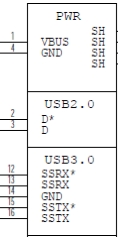
A SuperSpeed USB port has nine pins:
• VBUS
• GND
• D+/D−
• SSTX+/SSTX− (SuperSpeed data transmit)
• SSRX+/SSRX− (SuperSpeed data receive)
• GND_DRAIN for drain wire termination and managing EMI, RFI, and signal integrity
The D+/D− signal pins connect to UTMI pads. The SSTX/SSRX signal pins connect to UPHY and are handled by a single UPHY lane. As UPHY lanes are shared between PCIE and XUSB, UPHY lanes must be assigned according to the custom carrier board’s requirements.
UPHY Lane Assignment
Universal Physical Layer (UPHY) is a physical I/O interface layer that can serve multiple types of interfaces, e.g. USB and PCIe. A single UPHY lane can support multiple types of interfaces.
The Jetson P3449 carrier board is designed and verified for one USB 3.0 port. The verified use cases and their UPHY lane assignments are shown in the following tables.
Available outputs for the P3449 carrier board
Output Type
Number of Outputs
USB 3.0
1
PCIe
1 x4
UPHY lane assignment use cases
Lane
Pin Names
Functions
0
N/A
PCIe x1 C1
1
PEX_TX1 PEX_RX1
PCIe x4 C0 (L3/L2/L1/L0)
2
PEX_TX2 PEX_RX2
3
PEX_TX3 PEX_RX3
4
PEX_TX4 PEX_RX4
5
N/A
N/A
6
PEX_TX6 PEX_RX6
USB3.0 P0
Jetson Nano and the supporting software are designed to support the configurations in these tables. See Tegra X1 (SoC) Technical Reference Manual (TRM) and consult Jetson Nano Product Design Guide for further information before you design your custom board. (Note that Tegra X1 Technical Reference Manual applies to Jetson Nano as well as NVIDIA® Jetson™ TX1.)
Lane assignment can be defined by the PCIe subnode under xusb_padctl in the corresponding device tree file. The device tree’s xusb_padctl node follows the conventions of the document:
The PCIe subnode lists the functions assigned to UPHY lanes.
• nvidia,function: A string containing the name of the function to mux to the pin or group. It must be one of these values:
• xusb
• pcie-x1
• pcie-x4
Take the table of UPHY lane assignment use cases, for example. Create a PCIe subnode and property under xusb_padctl based on the device tree structure described above:
xusb_padctl@7009f000 {
...
pcie {
status = "okay"
lanes {
pcie-0 {
status = "okay"
nvidia,function = "pcie-x1";
};
pcie-1 {
status = "okay"
nvidia,function = "pcie-x4";
};
pcie-2 {
status = "okay"
nvidia,function = "pcie-x4";
};
pcie-3 {
status = "okay"
nvidia,function = "pcie-x4";
};
pcie-4 {
status = "okay"
nvidia,function = "pcie-x4";
};
pcie-5 {
status = "okay"
nvidia,function = "xusb";
};
pcie-6 {
status = "okay"
nvidia,function = "xusb";
};
};
...
};
Note:
UPHY lane 0 and UPHY lane 5 are not exposed, and can only be assigned to the pcie-x1 and xusb functions.
Required Device Tree Changes
This section gives step-by-step guidance for checking schematics and configuring USB ports in the device tree. All of the examples are based on the design of the Jetson Nano P3449 carrier board.
For a Host-Only Port
This section uses U27, a USB 3.0 Realtek SuperSpeed on-board hub, as an example of a host-only port.
Go Through the Schematics
Note:
The P3449 carrier board’s schematic file, P3449_B01_Concept_schematics.pdf, is included in Jetson Nano Developer Kit Carrier Board Design Files. Consult your NVIDIA representative for further information.
Check the USB 3.0 Realtek SuperSpeed hub on the P3449 carrier board and find the pin names of the wired socket to the P3448 SOM.
• USB 2.0 signal pins D+/D- (USB_DP/USB_DM) wire out from U27 and lead to module socket pins 115 (USB1_DN) and 116 (USB1_DP).
• USB 3.0 differential signal pairs (USP_SSTX* and USP_SSRX*) wire out from U27 and lead to module socket pins 161 (SBSS_RX_N), 163 (USBSS_RX_P), 166 (USBSS_TX_N), and 168 (USBSS_TX_P).
Through the schematic, you can conclude that for U27:
• The USB 2.0 signal pair is wired to UTMI pad 1 (USB2 port 1).
• The USB 3.0 signal pairs are wired to UPHY lane 6 (USB 3.0 port 0 according to UPHY lane mapping).
The xusb_padctl Node
The device tree’s xusb_padctl node follows the conventions of pinctrl-bindings.txt. It contains two groups of named pads and ports which describe USB2 and USB3 signals along with parameters and port numbers. The name of each parameter description subnode in pads and ports must be in the form <type>-<port_number>, where <type> is usb2 or usb3, and <port_number> is the associated port number.
The pads Subnode
The properties of the pads subnode are:
• nvidia,function: A string containing the name of the function to mux to the pin or group. Must be xusb.
The ports Subnode
• mode: A string that describes USB port capability. A port for USB2 must have this property. It must be one of these values:
• host
• device
• otg
• nvidia,usb2-companion: The USB2 port (0, 1, or 2) to which the port is mapped. A port for USB3 must have this property.
• nvidia,oc-pin: The overcurrent VBUS pin the port is using. The value must be positive or zero.
Note:
Overcurrent detection and handling for U27, the Realtek SuperSpeed hub on the P3499 carrier board, are controlled by the hub itself. Therefore, you need not set this property.
• vbus-supply: VBUS regulator for the corresponding UTMI pad. Set to &battery_reg for a dummy regulator.
Note:
As the Realtek SuperSpeed hub is always connected to the root hub port on a P3449, you need not control hub power, just enable it with VDD_HUB_3V3. Therefore, you must set dummy regulators for U27 on the P3449 carrier board.
For the detailed information about xusb_padctl, refer to the documentation at:
As an example, consider U27, the Realtek SuperSpeed hub, which is always connected to USB2 port 1 and USB3 port 0 on the root hub. Create a pad/port node and property list for U27 based on the device tree structure described above:
xusb_padctl: xusb_padctl@7009f000 {
...
pads {
usb2 {
status = "okay";
lanes {
...
usb2-1 {
nvidia,function = "xusb";
status = "okay";
};
...
};
};
pcie {
status = "okay";
lanes { ...//UPHY lane assignment
};
};
};
ports {
usb2-1 {
mode = "host";
vbus-supply = <&battery_reg>;
status = "okay";
};
...
usb3-0 {
nvidia,usb2-companion = <1>;
status = "okay";
};
...
};
};
Under the xusb Node
The Jetson Nano xHCI controller complies with xHCI specifications, which support both USB 2.0 HighSpeed/FullSpeed/LowSpeed and USB 3.0 SuperSpeed protocols.
• phys: Must contain an entry for each entry in phy-names.
• phy-names: Must include an entry for each PHY used by the controller. Names must be of the form <type>-<port_number>, where <type> is "usb2" or "usb3".
• nvidia,boost_cpu_freq: Set the value to which CPU frequency will be boosted. This is only the minimum frequency, DVFS can scale up CPU frequency further based on need and CPU loading. CPU boost frequency through PMQOS is enabled for the xHCI controller only when this field’s is greater than zero. The boost is applicable only for bulk and ISOC transfers; other endpoints do not need to be boosted.
• nvidia,boost_cpu_trigger: Minimum buffer length of the bulk or ISOC transfers beyond which to boost frequency.
• nvidia,xusb-padctl: A pointer to the xusb-padctl node.
For the detailed information about xHCI, see the documentation at:
Consider U27, the Realtek SuperSpeed hub, as an example. Create an xHCI node and property list for U27 based on the device tree structure described above:
USB On-The-Go, often abbreviated USB OTG or just OTG, is a specification that allows USB to act as a host or a device on the same port. A USB OTG port can switch back and forth between the roles of host and device.
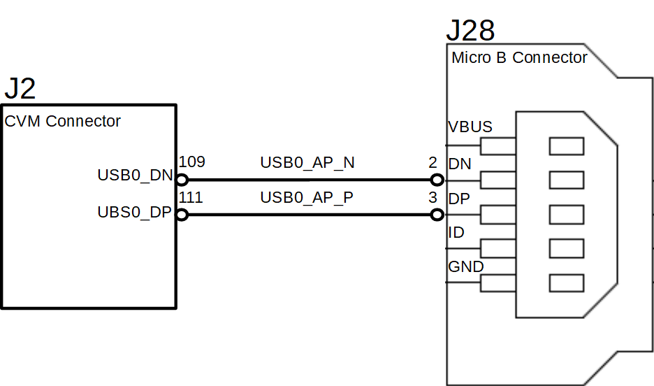
This section uses J28, a USB 2.0 Micro B connector, as an example of an OTG port.
An OTG port adds a fifth pin, called the ID pin, to the standard USB connector. An OTG cable has a USB Type A plug on one end and a Type B plug on the other end. The Type A plug’s ID pin is grounded, while the Type B plug’s ID pin is floating. A device with a Type A plug inserted becomes and OTG A-device (host), and a device with a Type B plug inserted becomes a B-device (device).
Note:
Because its ID pin is floating, J28 is fixed in the device role in the Jetson Nano Developer Kit. It cannot function as a host, e.g. to connect a flash drive, keyboard, or mouse.
Go Through the Schematics
Refer to the P3449 carrier board’s schematic file, P3449_B01_Concept_schematics.pdf, which is in Jetson Nano Developer Kit Carrier Board Design Files.
Check the USB connectors on the P3449 carrier board and find the wired socket location to the P3448 SOM.
• USB 2.0 signal pins D+/D− (DP and DN) wire out from J28 and lead to 111 (USB0_DP) and 109 (USB0_DN) on the module socket.
• The USB 2.0 signal pair is wired to UTMI pad 0 (USB2 port 0).
The External Connector Class (extcon)
External connectors, which may have different types of cables attached (USB, TA, HDMI, Analog A/V, and others), often have device drivers that detect state changes at the port, and separate device drivers that do something according to the state changes.
The External Connector Class, extcon, supports the use of a notifier for passing information such as state changes between device drivers.
Port switching between the roles of an OTG port is generally controlled by the host driver (xHCI) and device driver (xUDC), and can be defined by the state of the ID pin and the VBUS_DETECT pin.
Note:
Because its ID pin is floating, J28 is fixed in the device role in the Jetson Nano Developer Kit. It cannot function as a host, e.g. to connect a flash drive, keyboard, or mouse.
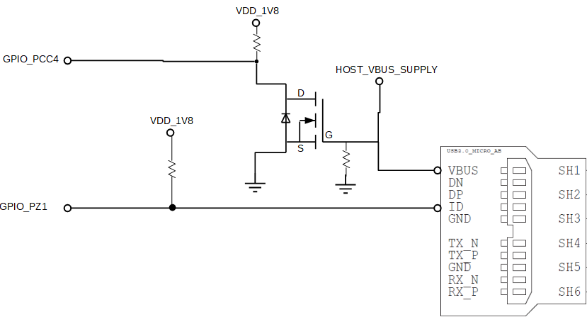
For example, suppose GPIO_PCC4 is the VBUS_DETECT pin and GPIO_PZ1 is the ID pin. To complete the device tree node:
1. Find the corresponding GPIO states on the VBUS_DETECT pin and ID pin.
Generally, the ID pin is designed as internal pull high (logical high). With a Type A plug connected the ID pin is pulled to ground (logical low), while with a Type B plug connected or no cable connected it remains logical high.
The operation of the VBUS_DETECT pin depends on the device’s design. Consider the following schematic, for example:
With a Type B plug connected VBUS_DETECT is logical low because VBUS is provided from an external power supply. When no cable is connected it is logical high.
Note:
VBUS_DETECT is initially logical high, then logical low because VBUS is provided by the host controller. Therefore, the state of the VBUS_DETECT pin does not matter when the OTG port is operating in the host role.
2. Create a table of GPIO states and their corresponding output cable states like the one in the following table.
GPIO states and corresponding output cable states
GPIO_PZ1 (ID)
GPIO_PCC4 (VBUS_DETECT)
EXTCON_STATE
1
1
0x0 (EXCON_NONE)
0
0
0x2 (EXTCON_USB_HOST)
0
1
0x2 (EXTCON_USB_HOST)
1
0
0x1 (EXTCON_USB)
Under the extcon Node
Port switching between the roles of an OTG port is defined by the state of the ID pin and the VBUS_DETECT pin and the settings of the external connector class.
Create an extcon device node and property list using the properties listed below and the table of GPIO states and cable states, above.
• compatible: Value must be extcon-gpio-states.
• extcon-gpio,name: Name of the extcon device.
• gpios: List of the GPIOs.
• extcon-gpio,irq-flags: IRQ flags for GPIO.
• extcon-gpio,debounce: Debounce time in milliseconds.
• extcon-gpio,wait-for-gpio-scan: Wait timeout in milliseconds for scanning all GPIOs’ states after a GPIO state change is detected and debounce time has passed.
• extcon-gpio,cable-states: GPIO states and their corresponding output cable states. The value is an array of byte values. Each even-numbered byte is a GPIO state, and the following odd-numbered byte is the corresponding output cable state.
• cable-connected-on-boot: Name of the output cable connected on boot, expressed as an index into extcon-gpio,out-cable-names. The first element is index 0, and so on. If not specified, the system assumes that no cable is to be connected. This property is valid if no GPIOs are provided for cable states.
• wakeup-source: A Boolean; true if the device can wake up the system.
For the detailed information about extcon, refer to the documentation at:
• Create an extcon device node and property list based on the device tree structure described above and the table of GPIO states and cable states. This example shows a node definition which assumes GPIO_PCC4 is the VBUS_DTECT pin and GPIO_PZ1 is the ID pin.
vbus_id_extcon: usb_otg {
compatible = "extcon-gpio-states";
extcon-gpio,name = "VBUS_ID";
extcon-gpio,wait-for-gpio-scan = <0>;
extcon-gpio,cable-states = <0x3 0x0
0x0 0x2
0x1 0x2
0x2 0x1>;
gpios = <&gpio TEGRA_GPIO(CC, 4) 0
&gpio TEGRA_GPIO(Z, 1) 0>;
extcon-gpio,out-cable-names =
<EXTCON_USB EXTCON_USB_HOST EXTCON_NONE>;
#extcon-cells = <1>;
};
The USB 2.0 Micro B connector, J28, has the connector’s ID pin floating and the VBUS_DETECT pin of the connector wired out to GPIO00, which corresponds to GPIO_PCC4. Hence J28 can only function in the device role.
This is the table of GPIO states on J28 and their corresponding output cable states:
GPIO_PCC4 (VBUS_DETECT)
EXTCON_STATE
1
0x0 (EXCON_NONE)
0
0x1 (EXTCON_USB)
This is the extcon device node and property list based on the device tree structure described above and the table of GPIO states and corresponding output cable states for GPIO_PCC4, customized for Jetson Nano, where the ID pin is floating the port is fixed in the device role:
vbus_id_gpio_extcon: usb_otg {
compatible = "extcon-gpio-states";
extcon-gpio,name = "VBUS";
extcon-gpio,wait-for-gpio-scan = <0>;
extcon-gpio,cable-states = <0x0 0x1
0x1 0x0>;
gpios = <&gpio TEGRA_GPIO(CC, 4) 0>;
extcon-gpio,out-cable-names =
<EXTCON_USB EXTCON_USB_HOST EXTCON_NONE>;
#extcon-cells = <1>;
};
Note:
Check the pinmux table for the GPIO that corresponds to the ID pin and VBUS_DETECT pin.
Under the xusb_padctl Node
xusb_padctl settings for an OTG port are the same as for a host-only port except that the mode must be otg.
For the example of J28, the USB 2.0 Micro B connector, create a pad/port node and property list:
xusb_padctl: xusb_padctl@7009f000 {
...
pads {
usb2 {
lanes {
usb2-0 {
nvidia,function = "xusb";
status = "okay";
};
...
};
};
pcie {
lanes {
...
};
};
};
ports {
usb2-0 {
mode = "otg";
vbus-supply = <&p3449_vdd_usb_vbus>;
status = "okay";
};
...
};
};
Under the xHCI Node
The xHCI settings for an OTG port are the same as for a host-only port except for these additional extcon settings:
• extcon-cables: OTG support. Must contain a pointer to the extcon-cable entry for the USB ID pin. When the extcon cable state is 0, the OTG port transitions to the host role.
• extcon-cable-names: Must be id.
• #extcon-cells: Number of cells in the extcon specifier. Must be 1.
For the example of J28, the USB2.0 Micro B connector, create an xHCI node and property list based on the device tree structure described in Under the xusb Node for a host-only port, plus the additional settings above:
The Jetson Nano xUDC controller supports both USB 2.0 HighSpeed/FullSpeed and USB 3.0 SuperSpeed protocols.
These are the device tree node properties that apply to the xUDC node:
• extcon-cables: OTG support. Must contains an extcon-cable entry that detects the USB VBUS pin. When the extcon cable state is 1, OTG port transitions to the device role.
• extcon-cable-names: Must be vbus.
• charger-detector: USB charger detection support. Must be the phandle of the USB charger detection driver DT node.
• phys: An array; must contain pointers to the nodes that define each PHY in phy-names.
• phy-names: An array; must contain an entry for each PHY used by the controller. Names must be in the form <type>-<port_number>, where <type> is usb2 or usb3.
• nvidia,boost_cpu_freq: The value to which CPU frequency is to be boosted. This is only the minimum frequency; DVFS can scale up CPU frequency further based on need and CPU load. CPU boost frequency through PMQOS is enabled for the xUDC controller only when this field’s value is greater than zero. The boost is applicable only to large bulk transfers on bulk endpoints; other endpoints do not need to be boosted.
• nvidia,xusb-padctl: A pointer to the xusb-padctl node.
For the detailed information about xUDC, refer to the documentation at:
For the example of J28, the USB2.0 Micro B connector, create an xUDC node and property list for J28 based on the device tree structure described above:
If you suspect a UPHY lane mapping issue, enter this command to check the lane assignments:
./devmem 0x7009f028
(The hexadecimal number is the register address of the UPHY lane mux. It may be considered a constant.)
Bits
Reset
Description
25-24
0x01
UPHY_LANE6
Each lane’s bits identify the function that owns the lane. Recognized values are:
• 0: PCIE_X1
• 1: USB3_SS
• 3: PCIE_X4
23-22
0x01
UPHY_LANE5
21-20
0x03
UPHY_LANE4
19-18
0x03
UPHY_LANE3
17-16
0x03
UPHY_LANE2
15-14
0x03
UPHY_LANE1
13-0
—
Reserved
If a target UPHY Lane is not owned by the correct function, check the values of the PCIe subnode and properties under xusb_padctl to be sure that the target lane is assigned correctly.
The temperature to fan speed mapping table can be modified with device tree properties.
The fan’s thermal zone temperature is approximated by the average of the CPU and GPU SOC thermal sensor readings. Fan speed is controlled by the PWM signal; its pulse width range is 0-255 units.
The mapping between temperature and fan speed is defined by thermal trips and fan cooling states. The thermal trips refer to the fan thermal zone’s temperature in degrees Celsius, and the fan cooling state are the PWM signal’s corresponding pulse widths. You can define trip temperatures and the corresponding cooling states by creating a custom fan mapping table.
The fan trip temperatures are defined by the active_trip_temps property in the file:
This section discusses some other considerations and recommendations to keep in mind when porting.
Boot Time Reduction
GNOME shell is the default display and window manager for Ubuntu 18.04. Although it brings a new look to the user experience it comes with performance and memory overhead problems. Many GDM3 and GNOME shell issues are known, with fixes under development. However, considering the Ubuntu release timelines and the trivial nature of the fixes, these fixes may not be backported to Ubuntu 18.04.
Therefore, below are some suggestions for reduce boot time by tweaking rootfs and kernel.
Root Filesystem
These changes to the root filesystem may reduce boot time.
• Enable autologin for GDM3 (saves about 14 to 19 seconds of boot time).
• Set power mode to MAXN (saves about 8 to 10 seconds of boot time).
• Use a lightweight display manager like LightDM. The LightDM service takes about 3 to 5 seconds to start.
To install and configure lightdm display manager, enter the commands:
sudo apt-get update
sudo apt-get install lightdm
sudo dpkg-reconfigure lightdm
• Use a lightweight window manager like LXDE. LXDE takes 3 to 4 seconds to bring up the desktop after login.
To install and enable LXDE and Compton, enter the commands:
sudo apt-get update
sudo apt-get install lxde compton
Create the configuration file /etc/xdg/autostart/lxde-compton.desktop, containing these commands:
[Desktop Entry]
Type=Application
Name=Compton (X Compositor)
GenericName=X compositor
Comment=A X compositor
TryExec=compton
Exec=compton --backend glx -b
OnlyShowIn=LXDE
Kernel
Pass the “quiet” option to the kernel reduces kernel boot time by about 10 seconds.
In /boot/extlinux/extlinux.conf in the target rootfs, set the APPEND parameter to quiet (or add quiet to the parameter if it is already defined:
APPEND ${cbootargs} quiet
Bring-Up Considerations
This section contains some factors to consider or provide for before begommomg the bring-up process.
• To change your project’s name, rename the flash configuration file:
• jetson-nano-sd.conf for a SKU 0000 device
• jetson-nano-qspi.conf for a SKU 0002 device)
• You need not specify an EEPROM board ID for your carrier board.
• If you don’t want to use the Dynamic Freq and Voltage Scaling feature, you can disable it with the kernel configuration parameter CONFIG_TEGRA_210_DVFS.
• If you want to change secondary boot storage to EMMC, you must specify the size of the EMMC in the appropriate configuration file:
• To flash QSPI only on a SKU 0000 device, jetson-nano-qspi.conf.
• To flash QSPI and SD card on a SKU 0000 device, jetson-nano-sd.conf.
• To flash eMMC on a SKU 0002 device, jetson-nano-emmc.conf.
You also must specify eMMC size in p3448-0000.conf.common.
Below are the parameters in the file which you must review.