When developing systems and application software with an NVIDIA® Jetson™ device and Linux, you run and test your code on an actual reference platform, such as the NVIDIA® Jetson Nano™ Developer Kit. Your code targets this hardware directly, rather than a software simulator or emulator.
Accordingly, you must acquire and set up your carrier board before using L4T. Consult your board documentation for guidance on setting up and configuring your board. See the sections below for additional notes.
• A USB cable to plug into the board recovery port
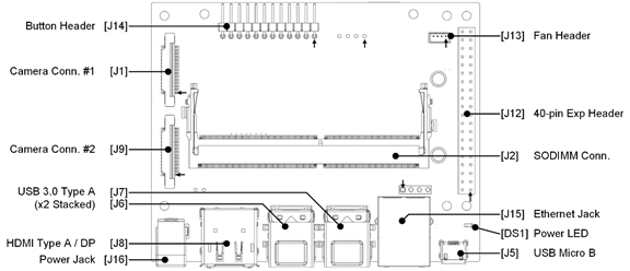
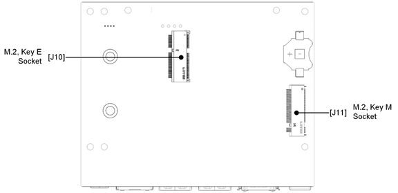
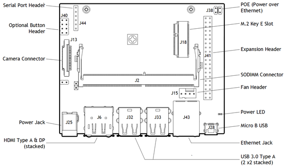
Platform Board Layout
Note:
Jetson TX2 series devices use the same carrier board as NVIDIA® Jetson™ TX1; only the Jetson module differs. Thus, the following diagram applies to both Jetson TX2 and Jetson TX1. The “Jetson TX1” label in the diagram itself is not significant.
Jetson TX1
This section describes hardware setup for NVIDIA Jetson TX1 devices.
Carrier Board Preparation
Although the carrier board supports a variety of peripheral devices, start developing your application with a board that has:
• A USB cable to plug in to the board recovery port.
Platform Board Layout
The Jetson TX1 carrier board is identical to the Jetson TX2 carrier board, shown in the Jetson TX2 section Platform Board Layout.
Enabling Bluetooth Audio
Hardware support for Bluetooth® audio varies by platform. The following table summarizes the support provided in each case;
Platform
SoC
Bluetooth Support
On SoC
Through M.2 key E connector; customer must add Bluetooth hardware on production systems *
Through M.2 Key E connector; customer must supply Bluetooth hardware
No Bluetooth support
Jetson Xavier NX
T194
X
Jetson Nano
T210
X
Jetson AGX Xavier series
T194
X
Jetson TX2 4GB
T186
X
Jetson TX2i
T186
X
Jetson TX2 (original, 8GB)
T186
X
Jetson TX1
T210
X
* Carrier boards have built-in Bluetooth support for development.
To ensure the Bluetooth software stack is conformant for the configuration, Bluetooth audio is disabled by default. If additional Bluetooth audio profiles are enabled, product conformance may be impacted.
Jetson modules include an on-board power monitor, the INA3221, to monitor the voltage and current of certain rails. L4T uses the power monitor to implement a system Electrical Design Point (EDP) management strategy which maximizes CPU and GPU performance within system EDP constraints for the platform.
The Jetson module feeds INA3221 outputs into SOC_THERM input. When one or more alert outputs are asserted, the SOC_THERM hardware reduces module power consumption to avoid violating current limits.
The power monitor accepts configuration data from powermon.dtsi (the source file). The following sections describe the device tree properties that you may need to change to configure the power monitor, and for each supported platform, the location of the file and a code snippet showing how the properties are used.
Power Monitor Device Tree Properties
These are the power monitor device tree properties that you may need to change to configure the power monitor.
• ti,continuous-config: Configuration register setting for INA3221 continues conversion mode. This determines which channels are enabled, bus voltage conversion time, and number of samples collected and averaged together.
• ti,trigger-config: Configuration register setting for INA3221 single shot conversion mode. This determines which channels enabled, bus voltage conversion time, and number of samples collected and averaged together.
• ti,rail-name: Name of the power rail connected to the INA3221 input channel.
• ti,shunt-resistor-mohm: Power rail sense resistor value, in milliohms.
• ti,current-warning-limit-ma: Channel average current limit in milliamperes. The INA3221 warning signal is asserted when the channel’s average current exceeds this limit, triggering CPU/GPU hardware throttling via Jetson SOCTHEM_OC.
• ti,current-critical-limit-ma: Channel instantaneous current limit in milliamperes. The INA3221 critical signal is asserted when the channel’s instantaneous current exceeds this limit, triggering CPU/GPU hardware throttling via Jetson SOCTHEM_OC.
Jetson Xavier NX
The INA3221 monitors the voltage and current of the following power rails:
• VDD_IN
• VDD_CPU_GPU_CV
• VDD_SOC
The alert outputs of the INA3221 include:
• CRIT
• WARN
Configuring the Voltage and Current Monitor
The Xavier NX module input power rail VDD_IN is connected to channel 0 and configured to trigger CPU/GPU hardware throttling when average current goes above 3000 mA or instantaneous current goes above 3600 mA.
The INA3221 monitors the voltage and current of the following power rails:
• VDD_IN
• VDD_CPU
• VDD_GPU
• VDD_SOC
• VDD_DRAM
• VDD_WIFI (original Jetson TX2 only)
The alert outputs of the INA3221 include:
• CRIT and WARN (tied together and routed to SoC input on SOC_THERM)
The outputs are fed into a SOC_THERM input on the Jetson module. When one or more alert outputs are asserted, the SOC_THERM hardware reacts to reduce module power consumption and avoid violating current limits.
Configuring the Voltage and Current Monitor
By default, the Jetson TX2 developer kit’s critical current limit of VDD_IN is set to the maximum possible value of 8190 mA. Therefore, it is not necessary to modify the critical current for lower input voltage unless you want to configure the critical current limit for a specific input voltage.
Jetson TX2
The powermon.dtsi file for the Jetson TX2 module is located at: