Jetson Orin NX Series and Jetson AGX Orin Series
This topic describes power and performance management features of NVIDIA® Jetson Orin™ NX series and NVIDIA® Jetson AGX Orin™ series devices. It describes the power, thermal, and electrical management features visible to software, as well as some tools and related techniques.
Note
The Jetson Orin NX Series and Jetson AGX Orin 32GB are supported only as emulated platforms from Jetson AGX Orin.
These devices’ power management features are very similar, and most of this document applies equally to both. For convenience, the text often refers to them by the shorter name Jetson Orin. This term is used solely for convenience, and is not a product name.
Jetson Orin and NVIDIA® Jetson™ Board Support Package (BSP) provide many features related to power management, thermal management, and electrical management. These features deliver the best user experience possible given the constraints of a particular platform. They help to create a user experience of:
Uniformly high performance
Excellent battery life
Perfect stability
Cool operation (the device is comfortable to touch)
Interacting Features
Power, thermal, and electrical management features place dynamic constraints on many operational settings (“knobs”), such as:
Clock gate settings
Clock frequencies
Power gate (or regulator enable) settings
Voltages
Processor power state (i.e., which idle state is selected for the CPU)
Peripheral power state (i.e., which idle state is selected for an I/O controller)
Chipset power state
Availability of CPU cores to the OS
Some of these knobs are constrained by more than one feature. For example, cpufreq implements load-based scaling, which adjusts the CPU frequency according to how busy the CPU is. CPU thermal management, however, can override the target frequency of cpufreq. Consequently, before you attempt to debug power, performance, thermal, or electrical problems, you must familiarize yourself with all of the power, thermal, and electrical management features in BSP.
Kernel Space Power Saving Features
This section describes BSP features that save power and extend battery life. Many of these features are implemented by the Linux kernel, with support from firmware and hardware, and without significant involvement from the user space.
Chipset Power States
The supported power states are listed in order of increasing flexibility or configurability:
Off: There is only one way for a system to be off.
Deep Sleep (SC7) offers a small amount of configurability. For example, before entering Deep Sleep, the software can select which hardware wake events can wake the chip from Deep Sleep.
Active state is extraordinarily flexible in terms of power and performance. It encompasses activity levels from low-power audio playback through peak performance. Power consumption in the Active state can range from tens of milliwatts to several watts.
Supported Power States
The supported power states are:
Power State |
Characteristics |
|
|---|---|---|
Off |
Power rails: None of the power rails supplying the SoC and DRAM are powered. State: No state is maintained in the SoC or DRAM. Exiting: Into Active state via cold boot. |
|
Deep Sleep (SC7) |
Power rails: State: The SoC maintains a small amount of state information in the PMC block. DRAM maintains the state. Exiting: Into Active state via a predefined set of wake events. |
|
Active |
Power rails: State: Software actively manages the power states of the devices that make up the SoC. Exiting: Software can initiate a transition from Active to any other power state. |
|
Power State Mapping to Linux
BSP maps chipset power states to Linux power states as follows.
Chipset power state |
Linux power state |
Comments |
|---|---|---|
Off |
Off |
— |
Deep Sleep (SC7) |
Suspend to RAM |
The software can choose whether to enter Deep Sleep before the OS enters Suspend. |
Active |
Running/Idle (display on or off) |
Many SoC devices may be idle or
disabled under driver control.
For example, |
Deep Sleep (SC7)
If the systemd init system is being used, you can initiate deep sleep from the user space with the following command:
$ sudo systemctl suspend
You can also use the following command:
$ sudo bash -c "echo mem > /sys/power/state"
The first method of entering deep sleep is preferred because it cooperates better with systemd, which maintains the Linux runlevel. If your system is not running systemd, use the second method.
The system can be awakened from deep sleep by common wake sources available on Jetson platforms:
Wake source |
Usage |
|---|---|
Power button |
Press and release the power button on the Jetson device. If the power button is not available, connect and disconnect the power button pin and ground. |
RTC alarm |
Before entering low power state, program the RTC alarm with the following command: $ sudo bash -c "echo +10 > /sys/class/rtc/rtc<x>/wakealarm"
where $ find /sys/class/rtc/* -maxdepth 0 -printf "%f:" -exec bash -c \
"cat {}/hctosys" \; | grep :1 | cut -d: -f1 | head -n1
|
USB type-C cable hotplug |
To flash the device, connect or disconnect a USB cable to the USB type-C port. |
USB remote |
Press any key on a USB keyboard connected to the device. |
Wake on LAN |
On another machine on the same LAN, enter: $ sudo etherwake -i <interface> <MAC_address_of_target>
|
SD card detection |
Insert or remove SD card. |
Clock and Voltage Management
Because clock frequency is proportional to voltage, dynamic voltage scaling is closely related to frequency scaling. For example, higher clock frequencies require higher voltages and vice versa.
Most clock register manipulation on Jetson Orin is handled by the Boot and Power Management (BPMP) firmware, which runs on the BPMP processor. A Linux kernel driver on the CPU exposes a somewhat simplified view of the physical clock tree to software on the main CPU via the Linux Common Clock Framework.
Each of the significant clock domains on the chip has its own dedicated clock source, known as a Noise Aware Frequency Lock Loop (NAFLL).
Regulator Framework
The Linux regulator framework provides an abstraction that allows regulator consumer drivers to dynamically adjust voltage or current regulators at runtime, without knowledge of the underlying hardware power tree.
The framework provides a mechanism that platform initialization code can use to declare a power tree topology and assign a driver that provides regulators for each node in the hardware power tree. Such a driver is called a regulator provider driver.
BSP configures the platform power tree appropriately for Jetson Orin. Additionally, drivers within BSP act as regulator consumers, where appropriate.
When you port BSP to a new platform, you must ensure that:
The platform power tree is configured to match the underlying hardware.
All drivers for peripheral devices use the regulator consumer APIs correctly.
The device tree and board configuration file information for your new platform avoid conflicts between functions using the same I/O pads. BSP drivers registering as regulator consumers can cause I/O pads on the chip to be unavailable for other functions.
The SoC core power rails (VDD_CORE, VDD_CPU, VDD_GPU, and VDD_CV) are under the direct control of the BPMP firmware. They are configured via the BPMP device tree blob (which is distinct from the Linux device tree blob).
CPU Power Management
The CPU power management strategy uses dynamic frequency scaling (DFS) with dynamic voltage scaling, idle power states, and core management tuned for the Jetson Orin architecture.
Frequency Management with cpufreq
BSP implements CPU dynamic frequency scaling with the Linux
cpufreq subsystem. The cpufreq subsystem comprises:
Platform drivers to implement the clock adjustment mechanism
Governors to implement frequency scaling policies
A core framework to connect governors to platform drivers
The policy for frequency scaling depends on which cpufreq governor is
selected at runtime.
For details, see the information at:
<top>/kernel/kernel-5.10/Documentation/admin-guide/pm/cpufreq.rst
For each Jetson platform, NVIDIA selects a cpufreq
governor and tunes it to achieve a balance between power and performance.
When a governor requests a CPU frequency change, the cpufreq platform
driver reconciles that request with constraints imposed by thermal or
electrical limits, and updates the CPU clock speed.
Jetson Orin uses an NAFLL to clock each CPU. The NAFLLs are configured for Adaptive Voltage and Frequency Scaling (AVFS). Hardware, with the assistance of the BPMP firmware, ensures that the CPU voltage is appropriate for the NAFLL to deliver requested CPU frequencies.
Idle Management with cpuidle
The Linux cpuidle infrastructure supports the implementation of
SoC-specific idle states for each CPU core. cpuidle lacks direct support
for idle states that are applicable to an entire CPU cluster or that
extend beyond a CPU cluster.
For more information about the Linux cpuidle infrastructure, see:
<top>/kernel/kernel-5.10/Documentation/admin-guide/pm/cpuidle.rst
CPU Idle
NVIDIA uses the generic upstream psci_idle driver that plugs into the cpuidle framework to enable CPU idle power management.
For each core there is an idle task that is scheduled when no other
runnable tasks are left in that core’s run queue. This task places
the core in a low-power state selected by the cpuidle governor. The core
stays in that state until an interrupt wakes it up to process more work.
When the last active core in a CPU cluster goes into an idle or offline state, the idle task puts the entire CPU cluster in a low-power state.
Idle States
The table below summarizes the CPU core and cluster idle states available on Jetson Orin, and the BSP software support for them.
Core states are denoted as Cx states, and cluster states are denoted as CCx states.
Type of state |
State |
Meaning |
Software support? |
|---|---|---|---|
Core state |
C1 |
Clock gating |
Yes |
C7 |
Core Power gating |
Yes |
|
Cluster state |
CC7 |
Cluster Power gating |
Yes |
To enable CPU idle
To enable CPU idle you must enable the appropriate kernel configuration option and the appropriate device tree node. Enabling either one alone is not effective.
To enable CPU idle in the configuration file, set these options:
CONFIG_CPU_IDLE=y
CONFIG_CPU_IDLE_MULTIPLE_DRIVERS=y
CONFIG_CPU_IDLE_GOV_MENU=y
CONFIG_DT_IDLE_STATES=y
CONFIG_ARM_CPUIDLE=y
CONFIG_ARM_PSCI_CPUIDLE=y
CONFIG_ARM_PSCI_CPUIDLE_DOMAIN=y
To disable cpuidle at boot time
Disable the device tree node
psci:psci { compatible = "arm,psci-1.0"; method = "smc"; cpu_off = <0x84000002>; cpu_on = <0xc4000003>; cpu_suspend = <0xc4000001>; status = "disable"; };
To display CPU idle status
Enter these commands to determine whether CPU idle is enabled by sysfs:
$ cat /sys/devices/system/cpu/cpuidle/current_driver
If CPU idle is enabled, the command displays:
psci_idle
To enable/disable a core power state at boot time
To enable a core power state, set the following properties of the appropriate core state node:
status to
"okay"min-residency-usto a reasonable value
For example, to enable power state C7 with
min-residency-us= 5000:c7 { compatible = "arm,idle-state"; state-name = "Core powergate"; wakeup-latency-us = <0x1388>; min-residency-us = <5000>; arm,psci-suspend-param = <0x40000007>; status = "okay"; phandle = <0x83>; };To disable a core power state, use either of the following procedures.
Remove or disable the appropriate core state node.
or
Modify the appropriate core state node by setting the
min-residency-usproperty to a high value, e.g.,0xffffffff.
For example, to disable power state C7:
c7 {
    compatible = "arm,idle-state";
    state-name = "Core powergate";
    wakeup-latency-us = <0x1388>;
    min-residency-us = <0xffffffff>;
    arm,psci-suspend-param = <0x40000007>;
    status = "okay";
    phandle = <0x83>;
};
To get and set a CPU core’s power state
The pathnames of the nodes that represent core power states are:
/sys/devices/system/cpu/cpu<x>/cpuidle/state<y>
Where:
<x>is a core ID.<y>is the index of the core power state: 0 for C1, or 1 for C7.
Note
A core power state’s status is 1 if the state is disabled, and 0 if it is enabled—the reverse of the usual Boolean sense of 0 and 1.
To get the status of core power state <y> on core <x>, read the
appropriate node. To set the status, write an ASCII 0 to 1 to the node.
Following are several useful commands for getting and setting the core power state:
To display the name of the core power state with index
<y>, enter the command:$ cat /sys/devices/system/cpu/cpu<x>/cpuidle/state<y>/name
For example, this command displays the name of state0:
$ cat /sys/devices/system/cpu/cpu<x>/cpuidle/state0/name
To get the status of core power state with index
<y>on core<x>:$ cat /sys/devices/system/cpu/cpu<x>/cpuidle/state<y>/disable
To change the status of core power state with index
<y>on CPU core<x>:$ echo <b> > /sys/devices/system/cpu/cpu<x>/cpuidle/state<y>/disable
To get the per-core state usage statistics
To get the number of times the kernel requested a specified core to enter a specified state, read this node:
$ cat /sys/devices/system/cpu/cpu<x>/cpuidle/state<y>/usage
To get the number of times a specified core actually entered a specified state, enter the command:
$ cat /sys/kernel/debug/tegra_mce/cstats
For example, to get the number of times that core 2 has entered power state1, enter the command:
$ cat /sys/devices/system/cpu/cpu2/cpuidle/state1/usage
To get the total time in microseconds that a specified core has spent in a specified state since boot, read the following device:
$ cat /sys/devices/system/cpu/cpu<x>/cpuidle/state<y>/time
Memory Power Management
NVIDIA SoC chipsets include power saving features whose operation is largely invisible to software at runtime. Most of those features are statically enabled at boot, according to settings in the boot configuration table (BCT).
Additionally, BSP implements Dynamic Voltage and frequency scaling for the memory controller (EMC/MC) and DRAM to save power. The EMC BCT and DVFS table are specific to the board design. The EMC DVFS table is included in the platform BPMP device tree file.
EMC Frequency Scaling Policy
The following factors affect EMC frequency scaling policy at runtime:
The entries in the EMC DVFS table
The average memory bandwidth used (as measured by hardware)
Requests made by various device drivers (cpufreq, graphics drivers, USB, HDMI®, and display)
Any limits dynamically imposed by thermal throttling
Supported Modes and Power Efficiency
Jetson Orin is designed with a high efficiency Power Management Integrated Circuit (PMIC), voltage regulators, and power tree to optimize power efficiency. It supports three optimized power budgets, such as 10 watts, 15 watts, and 30 watts. For each power budget, several configurations are possible with various CPU frequencies and number of cores online.
Capping the memory, CPU, and GPU frequencies, and number of online CPU, GPU TPC, DLA and PVA cores at a prequalified level confines the module to the target mode. The configurations predefined by NVIDIA are as follows.
| NVP Model clock configuration for Jetson Orin NX 8GB | ||||||
|---|---|---|---|---|---|---|
| Property | Mode | |||||
| MAXN* | 15W | 20W | ||||
| Power budget | n/a | 15W | 20W | |||
| Mode ID | 0 | 1 | 2 | |||
| Online CPU | 6 | 4 | 6 | |||
| CPU maximal frequency (MHz) | 1971.2 | 1420.8 | 1497.6 | |||
| GPU TPC | 4 | 2 | 4 | |||
| GPU maximal frequency (MHz) | 765 | 624.75 | 420.75 | |||
| DLA cores | 1 | 1 | 1 | |||
| DLA Core maximal frequency (MHz) | 614.4 | 614.4 | 614.4 | |||
| DLA Falcon maximal frequency (MHz) | 294.4 | 294.4 | 294.4 | |||
| PVA cores | 1 | 0 | 1 | |||
| PVA VPS maximal frequency (MHz) | 704 | 115 | 512 | |||
| PVA AXI maximal frequency (MHz) | 486.4 | 115 | 358.4 | |||
| Memory maximal frequency (MHz) | 3200 | 3200 | 3200 | |||
|
SoC clocks maximal frequency (MHz) All modes |
|
|||||
| * The default mode is MAXN (mode ID 0). | ||||||
| NVP Model clock configuration for Jetson Orin NX 16GB | ||||||
|---|---|---|---|---|---|---|
| Property | Mode | |||||
| MAXN* | 15W | 25W | ||||
| Power budget | n/a | 15W | 25W | |||
| Mode ID | 0 | 1 | 2 | |||
| Online CPU | 8 | 4 | 8 | |||
| CPU maximal frequency (MHz) | 1984 | 1651.2 | 1497.6 | |||
| GPU TPC | 4 | 2 | 4 | |||
| GPU maximal frequency (MHz) | 918 | 624.75 | 420.75 | |||
| DLA cores | 2 | 2 | 2 | |||
| DLA Core maximal frequency (MHz) | 614.4 | 614.4 | 614.4 | |||
| DLA Falcon maximal frequency (MHz) | 294.4 | 294.4 | 294.4 | |||
| PVA cores | 1 | 0 | 1 | |||
| PVA VPS maximal frequency (MHz) | 704 | 115 | 512 | |||
| PVA AXI maximal frequency (MHz) | 486.4 | 115 | 358.4 | |||
| Memory maximal frequency (MHz) | 3200 | 3200 | 3200 | |||
|
SoC clocks maximal frequency (MHz) All modes |
|
|||||
| * The default mode is MAXN (mode ID 0). | ||||||
| NVP Model clock configuration for Jetson AGX Orin 32GB | ||||||||
|---|---|---|---|---|---|---|---|---|
| Property | Mode | |||||||
| MAXN* | 15W | 30W | 40W | |||||
| Power budget | n/a | 15W | 30W | 40W | ||||
| Mode ID | 0 | 1 | 2 | 3 | ||||
| Online CPU | 8 | 4 | 8 | 8 | ||||
| CPU maximal frequency (MHz) | 2188.8 | 1113.6 | 1728 | 1497.6 | ||||
| GPU TPC | 7 | 3 | 4 | 7 | ||||
| GPU maximal frequency (MHz) | 930.75 | 420.75 | 624.75 | 828.75 | ||||
| DLA cores | 2 | 2 | 2 | 2 | ||||
| DLA Core maximal frequency (MHz) | 1408 | 614.4 | 1369.6 | 1228.8 | ||||
| DLA Falcon maximal frequency (MHz) | 742.4 | 294.4 | 729.6 | 652.8 | ||||
| PVA cores | 1 | 1 | 1 | 1 | ||||
| PVA VPS maximal frequency (MHz) | 704 | 307.2 | 512 | 704 | ||||
| PVA AXI maximal frequency (MHz) | 486.4 | 217.6 | 358.4 | 486.4 | ||||
| Memory maximal frequency (MHz) | 3200** | 2133 | 3200** | 3200** | ||||
|
SoC clocks maximal frequency (MHz) All modes |
|
|||||||
|
* The default mode is MAXN (mode ID 0). ** The EMC, scf, and hub clocks max frequencies are different for the jetson-agx-orin-devkit and the jetson-agx-orin-devkit-maxn flash configs. jetson-agx-orin-devkit settings - emc = 3199 MHz, scf/hub clock = 933 MHz jetson-agx-orin-devkit-maxn settings - emc = 3200 MHz, scf/hub clock = 1067 MHz |
||||||||
| NVP Model clock configuration for Jetson AGX Orin 64GB | ||||||||
|---|---|---|---|---|---|---|---|---|
| Property | Mode | |||||||
| MAXN* | 15W | 30W | 50W | |||||
| Power budget | n/a | 15W | 30W | 50W | ||||
| Mode ID | 0 | 1 | 2 | 3 | ||||
| Online CPU | 12 | 4 | 8 | 12 | ||||
| CPU maximal frequency (MHz) | 2201.6 | 1113.6 | 1728 | 1497.6 | ||||
| GPU TPC | 8 | 3 | 4 | 8 | ||||
| GPU maximal frequency (MHz) | 1301 | 420.75 | 624.75 | 828.75 | ||||
| DLA cores | 2 | 2 | 2 | 2 | ||||
| DLA Core maximal frequency (MHz) | 1600 | 614.4 | 1369.6 | 1369.6 | ||||
| DLA Falcon maximal frequency (MHz) | 844.8 | 294.4 | 729.6 | 729.6 | ||||
| PVA cores | 1 | 1 | 1 | 1 | ||||
| PVA VPS maximal frequency (MHz) | 1152 | 307.2 | 512 | 704 | ||||
| PVA AXI maximal frequency (MHz) | 832 | 217.6 | 358.4 | 486.4 | ||||
| Memory maximal frequency (MHz) | 3200** | 2133 | 3200** | 3200** | ||||
|
SoC clocks maximal frequency (MHz) All modes |
|
|||||||
|
* The default mode is MAXN (mode ID 0). ** The EMC, scf, and hub clocks max frequencies are different for the jetson-agx-orin-devkit and the jetson-agx-orin-devkit-maxn flash configs. jetson-agx-orin-devkit settings - emc = 3199 MHz, scf/hub clock = 933 MHz jetson-agx-orin-devkit-maxn settings - emc = 3200 MHz, scf/hub clock = 1067 MHz |
||||||||
Power Mode Controls
You can display and change the power mode with the nvpmodel command.
To change the power mode, enter the command:
$ sudo /usr/sbin/nvpmodel -m <x>
Where
<x>is the power mode ID (i.e. 0, 1, 2 or 3).Alternatively, use the nvpmodel GUI front end. For more information, see nvpmodel GUI, later in this topic.
After you set a power mode, the module stays in that mode until you change it. The mode persists across power cycles and SC7.
Note
GPU tpc_pg_mask can be set once before the GPU golden context is created.
If the nvpmodel power mode change requires to set the different tpc_pg_mask
value then the system reboot is required.
Example:
ubuntu@jetson:~$ sudo nvpmodel -m 2
NVPM ERROR: Error writing 240 to /sys/devices/gpu.0/tpc_pg_mask: 19
NVPM WARN: Reboot required for changing to this power mode: 2
NVPM WARN: DO YOU WANT TO REBOOT NOW? enter YES/yes to confirm:
Type YES or yes to initiate reboot or press any other key to cancel.
The settings will be in effect after the reboot.
Ignore the NVPM ERROR: Error writing 240 to /sys/devices/gpu.0/tpc_pg_mask: 19 statement
as this is just for the information while change in GPU tpc_pg_mask.
To display the current power mode, enter the command:
$ sudo /usr/sbin/nvpmodel -q
Alternatively, see the mode displayed to the right of the NVIDIA icon in the nvpmodel window’s menu bar. For more information, see nvpmodel GUI, later in this topic.
To add a custom power mode definition, edit this file:
/etc/nvpmodel.conf
This is an example entry for mode 2:
< POWER_MODEL ID=2 NAME=MODE_15W >
CPU_ONLINE CORE_0 1
CPU_ONLINE CORE_1 1
CPU_ONLINE CORE_2 1
CPU_ONLINE CORE_3 1
CPU_ONLINE CORE_4 0
CPU_ONLINE CORE_5 0
CPU_ONLINE CORE_6 0
CPU_ONLINE CORE_7 0
CPU_DENVER_0 MIN_FREQ 1200000
CPU_DENVER_0 MAX_FREQ 1200000
CPU_DENVER_1 MIN_FREQ 1200000
CPU_DENVER_1 MAX_FREQ 1200000
GPU MIN_FREQ 0
GPU MAX_FREQ 670000000
EMC MAX_FREQ 1331200000
DLA_CORE MAX_FREQ 750000000
DLA_FALCON MAX_FREQ 450000000
PVA_VPS MAX_FREQ 550000000
PVA_CORE MAX_FREQ 385000000
The unit of measure for CPU frequency is kilohertz. The unit for GPU and EMMC frequency is hertz. You must assign each custom mode a unique number in the ID field. Test your use case to determine:
How many active cores to use
The frequency for each CPU cluster, and the GPU and EMC frequencies
The frequencies you select are subject to the MaxN limit defined in mode 0.
To learn about other options, enter the command:
$ /usr/sbin/nvpmodel -h
Fan Profile Control
Jetson Orin supports two profiles of fan operation named “quiet” and “cool.”
Userspace fan speed control daemon nvfancontrol manages fan speed based on the trip point temperatures configured for the selected profile.
Fan Profile Configuration
Every fan speed step is associated with the trip point temperature and corresponding hysteresis. The following table shows the configurations predefined by NVIDIA.
| Fan profile configuration for Jetson AGX Orin series | ||||||
|---|---|---|---|---|---|---|
| Fan profile “quiet” | ||||||
| Trip temperature* | 0 | 10 | 11 | 23 | 60 | 105 |
| Hysteresis* | 0 | 0 | 0 | 0 | 0 | 0 |
| Fan PWM value | 255 | 255 | 171 | 171 | 66 | 66 |
| Fan RPM value | 2900 | 2900 | 1940 | 1940 | 750 | 750 |
| Fan profile “cool” | ||||||
| Trip temperature* | 0 | 10 | 11 | 30 | 60 | 105 |
| Hysteresis* | 0 | 0 | 0 | 0 | 0 | 0 |
| Fan PWM value | 255 | 255 | 215 | 215 | 66 | 66 |
| Fan RPM value | 2900 | 2900 | 2440 | 2440 | 750 | 750 |
| * Trip temperature and hysteresis in degrees Celsius. | ||||||
| * Trip temperature is the TMARGIN temperature. | ||||||
nvfancontrol
nvfancontrol is a userspace fan speed control daemon. This manages the fan speed based on the temperature-to-fan-speed mapping table in the nvfancontrol configuration file.
There are some basic elements in the nvfancontrol service, including Tmargin, kickstart PWM, fan profile, fan control, and fan governor. All of these can be programmed via the configuration file based on the user’s preferences. This chapter will explain each of them in the following sections.
nvfancontrol.conf
Location:
/etc/nvfancontrol.conf
Please find below the example nvfancontrol.conf file for the Jetson Orin:
POLLING_INTERVAL 2
<FAN 1>
    TMARGIN ENABLED
    FAN_GOVERNOR pid {
            STEP_SIZE 10
    }
    FAN_GOVERNOR cont {
            STEP_SIZE 10
    }
    FAN_CONTROL close_loop {
            RPM_TOLERANCE 100
    }
    FAN_PROFILE cool {
            #TEMP   HYST    PWM     RPM
            0       0       255     2900
            10      0       255     2900
            11      0       215     2440
            30      0       215     2440
            60      0       66      750
            105     0       66      750
    }
    FAN_PROFILE quiet {
            #TEMP   HYST    PWM     RPM
            0       0       255     2900
            10      0       255     2900
            11      0       171     1940
            23      0       171     1940
            60      0       66      750
            105     0       66      750
    }
    THERMAL_GROUP 0 {
            GROUP_MAX_TEMP 105
            #Thermal-Zone Coeffs Max-Temp
            CPU-therm 20,0,0,0,0,0,0,0,0,0,0,0,0,0,0,0,0,0,0,0 0
            GPU-therm 20,0,0,0,0,0,0,0,0,0,0,0,0,0,0,0,0,0,0,0 0
            SOC0-therm 20,0,0,0,0,0,0,0,0,0,0,0,0,0,0,0,0,0,0,0 0
            SOC1-therm 20,0,0,0,0,0,0,0,0,0,0,0,0,0,0,0,0,0,0,0 0
            SOC2-therm 20,0,0,0,0,0,0,0,0,0,0,0,0,0,0,0,0,0,0,0 0
    }
    FAN_DEFAULT_CONTROL close_loop
    FAN_DEFAULT_PROFILE cool
    FAN_DEFAULT_GOVERNOR cont
    KICKSRART_PWM 64
Default Fan Profile
For Jetson Orin the fan profile is set to “cool” by default. It is defined as FAN_DEFAULT_PROFILE in the configuration file /etc/nvfancontrol.conf.
To change the default fan profile
To change the fan profile, complete the following steps:
Stop the
nvfancontrolsystemd service:sudo systemctl stop nvfancontrol
Set the default fan profile by putting the following property in
/etc/nvfancontrol.conf:FAN_DEFAULT_PROFILE <fan_profile>
Where <fan_profile> is quiet or cool.
Remove the status file:
sudo rm /var/lib/nvfancontrol/status
Start the
nvfancontrolsystemd service:sudo systemctl start nvfancontrol
To identify the current fan profile
Enter the command:
$ sudo nvfancontrol -q
Example:
$ sudo nvfancontrol -q
FAN1:FAN_PROFILE:cool
...
...
Once you set a fan profile, the module stays in that profile until you change it. The profile persists across power cycles and SC7.
Fan Profile Table
The fan profile table contains the mapping between the temperature and the fan speed. It also contains the hysteresis value for each step.
Syntax:
FAN_PROFILE <fan_profile_name> {
        <temp>  <hyst>  <pwm>   <rpm>
}

Where:
<fan_profile_name>: Fan Profile Name
<temp>: Temperation step in degree celcius
<hyst>: Hysteresis step
<pwm>:  Fan PWM value
<rpm>:  Fan RPM value
Example:
FAN_PROFILE cool {
        #TEMP   HYST    PWM     RPM
        0       0       255     2900
        10      0       255     2900
        11      0       215     2440
        30      0       215     2440
        60      0       66      750
        105     0       66      750
}
TMARGIN
TMARGIN temperature is the difference between the maximum allowable temperature and the current thermal zone temperature. For example, if the maximum allowable temperature of CPU-therm is 105 degree Celsius, and the current temperature of CPU-therm is 45 degree Celsius, the current TMARGIN temperature of CPU-therm is 60 degree Celsius (105 - 45).
Kickstart PWM
The minimal required PWM value to start the fan from complete stop state is called kickstart PWM. The fan might not start spinning if PWM value is lower than kickstart PWM.
Thermal Group
THERMAL_GROUP contains the list of thermal zones considered for calculating the trip temperature and the group max temperature for calculating the TMARGIN temperature.
This section contains:
Thermal Group Max temperature:
GROUP_MAX_TEMP <temp_in_degree_celcius>
This parameter is used only in case when TMARGIN is ENABLED. The Tmargin temperature is calculated as shown in TMARGIN section.
Thermal zone name, coefficients and the thermal zone max temperature:
<thermal_zone_name> <coeff_0>,<coeff_2>....,<coeff_19> <thermal_zone_max_temp>

Where:
<thermal_zone_name>: Thermal zone name
<coeff_0..coeff_19>: Coefficients used for calculating weighted average. Please note that
                     only <coeff_0> is taken into consideration as of now.
<thermal_zone_max_temp>: Thermal zone max temperature. This is used only when Tmargin
                         is ENABLED. If GROUP_MAX_TEMP specified then this temperature
                         will be ignored.
Here is an example for calculating weighted average temperature with Tmargin enabled. Consider that the current CPU-therm is 40 degree Celsius, GPU-therm is 35 degree Celsius, SOC0-therm is 39 degree Celsius, SOC1-therm is 39 degree Celsius, and SOC2-therm is 39 degree Celsius, then weighted average Tmargin temperature = (105 - 40) * 0.2 + (105 - 35) * 0.2 + (105 - 39) * 0.2 + (105 - 39) * 0.2 + (105 - 39) * 0.2 = 66 degree Celsius with below thermal group:
THERMAL_GROUP 0 {
        GROUP_MAX_TEMP 105
        #Thermal-Zone Coeffs Max-Temp
        CPU-therm 20,0,0,0,0,0,0,0,0,0,0,0,0,0,0,0,0,0,0,0 0
        GPU-therm 20,0,0,0,0,0,0,0,0,0,0,0,0,0,0,0,0,0,0,0 0
        SOC0-therm 20,0,0,0,0,0,0,0,0,0,0,0,0,0,0,0,0,0,0,0 0
        SOC1-therm 20,0,0,0,0,0,0,0,0,0,0,0,0,0,0,0,0,0,0,0 0
        SOC2-therm 20,0,0,0,0,0,0,0,0,0,0,0,0,0,0,0,0,0,0,0 0
}
Fan Control
Here are the fan control types in the nvfancontrol service:
open-loop:
The open-loop fan control adjusts the fan speed by setting the desired PWM value based on the current trip temperature step. The RPM values in the profile are ignored.
closed-loop:
The closed-loop fan control makes the fan spin close to the desired RPM value based on the current trip temperature step. The PWM values in the profile are ignored.
To have the fan spin at the exact same speed as the target RPM, there will be a performance drop and the risk of shorter fan life due to the constant adjustment of the speed. So, there is a programmable tolerance value between the target RPM and the current RPM value (an rpm difference within 100 is acceptable in the below example):
FAN_CONTROL close_loop {
        RPM_TOLERANCE 100
}
Fan Governor
The fan governor decides the fan speed control logic based on the fan profile. There are two kinds of fan governors in the nvfancontrol service: pid and cont.
The following profile with Tmargin enabled and open-loop control can be used to explain how different fan governors handle it:
TMARGIN ENABLED
FAN_PROFILE cool {
        #TEMP   HYST    PWM     RPM
        0       0       255     2900
        10      0       255     2900
        11      0       215     2440
        30      0       215     2440
        60      0       66      750
        105     0       66      750
}
pid:
The pid governor will change the fan speed only when the weighted average temperature crosses the trip temperature step. The curve between the weighted average temperature and fan speed resembles a stair.
For example, when a Tmargin weighted average decreasing, and the Tmargin weighted average is 70 degree Celsius, the PWM will be set to 66. Later even when the Tmargin weighted average decreases to 60 degree Celsius, the PWM will still be set to 66. When the Tmargin weighted average decreases to 59 degree Celsius, the PWM will be set to 215 until the next trip temperature step is crossed.
cont:
The cont governor will linearly interpolate the fan speed based on the upper and lower fan speed between the trip temperature steps. Compared to the pid governor, the curve between weighted average temperature and fan speed is more continuous.
For example, when the current Tmargin weighted average is 45 degree Celsius, the PWM will be set to 140 (215 + (45 - 30) * (66 - 215) / (60 - 30)).
Hysteresis in nvfancontrol
In nvfancontrol, hysteresis is used to define the fan speed change temperature threshold when using pid governor.
Consider below profile with Tmargin enabled:
TMARGIN ENABLED
FAN_PROFILE cool {
        #TEMP   HYST    PWM     RPM
        0       0       255     2900
        18      9       255     2900
        30      11      202     2300
        45      11      149     1700
        60      14      88      1000
        105     0       0       0
}
The fan will be turned on when the Tmargin temperature reaches 60 degree Celsius. Later when the Tmargin temperature keeps increasing, after the Tmargin temperature goes over 74 degree Celsius (60 + 14 = 74) the fan will be turned off.
Polling Interval
nvfancontrol daemon polls the thermal zone temperatures at the time interval specified by POLLING_INTERVAL and sets the fan speed value specified as per TEMPERATURE - FAN SPEED mapping table.
Syntax:
POLLING_INTERVAL <time_in_seconds>
TMARGIN Configuration
TMARGIN configuration needs to be specified in order for nvfancontrol daemon to depict the Fan Profile Table correctly.
TMARGIN ENABLED Case:
Formula to calculate the Tmargin temperature:
Tmargin_sensor_temp = GROUP_MAX_TEMP -OR- <thermal_zone_max_temp> - <current_thermal_zone_temp>
Formula to calculate Tmargin weighted average of the thermal group sensors:
Tmargin_thermgroup_weighted_average = Tmargin_sensor0_temp * sensor0_weight_ratio + Tmargin_sensor1_temp * sensor1_weight_Ratio + ...

Where:
Tmargin_sensor<x>_temp - Tmargin sensor temperature calculated using above formula.
sensor<x>_wight_ratio - Currently only <coeff_0> value is considered for weight ratio as mentioned in section "Thermal Group"
x - sensor number
TMARGIN ENABLED Table:
    TMARGIN ENABLED
    FAN_PROFILE cool {
            #TEMP   HYST    PWM     RPM
            0       0       255     2900
            10      0       255     2900
            11      0       215     2440
            30      0       215     2440
            60      0       66      750
            105     0       66      750
    }

Example:

Temperature steps defined in the above table are the Tmargin temperatures
calculated using the formula mentioned at the start of this section.

Consider that the GROUP_MAX_TEMP is set as 105, the current fan governor is
continuous, and the current fan control is closed-loop. So, as specified in the
above temperature-to-fan-speed mapping table, the Tmargin trip temperature
step 60 degree Celsius corresponds to (105 - 60) = 45 degree Celsius, which
is the weighted average of the thermal zone temperature.

When the weighted average of the thermal zone temperature reaches 46
degree Celsius (Tmargin temperature 59 degree Celsius), then nvfancontrol
sets the fan RPM to around 806 (the linear interpolated value between 750 and
2440).

In the above table, the fan RPM value will stay at 750 when the weighted
average of the thermal zone temperature falls between 0 degree Celsius and
45 degree Celsius (the Tmargin temperature between 105 degree Celsius and 60
degree Celsius).
TMARGIN DISABLED Case:
Formula to calculate weighted average of the thermal group sensors:
thermgroup_weighted_average = sensor0_temp * sensor0_weight_ratio + sensor1_temp * sensor1_weight_Ratio + ...

Where:
sensor<x>_temp - Current thermal zone temperature.
sensor<x>_wight_ratio - Currently only <coeff_0> value is considered for weight ratio as mentioned in section "Thermal Group"
x - sensor number
TMARGIN DISABLED Table:
    TMARGIN DISABLED
    FAN_PROFILE quiet {
            #TEMP   HYST    PWM     RPM
            0       0       0       0
            50      18      77      1000
            63      8       120     2000
            72      8       160     3000
            81      8       255     4000
    }

Example:

Temperature steps defined in the above table are the weighted average
of the actual thermal zone temperature.

Consider that the current fan governor is pid, and the current fan control is
open-loop. As specified in the above temperature-to-fan-speed mapping table,
when the actual weighted average of the thermal zone temperature reaches
50 degree Celsius and keeps rising, then nvfancontrol sets the fan PWM to
77. The fan PWM will stay at 77 until the weighted average of the thermal zone
temperature reaches 63 degree Celsius and so on.
Thermal Management
Thermal management is essential for system stability and quality of user experience. Jetson Orin thermal management provides the following capabilities:
Sensing for on-board and on-chip thermal sensor temperature reporting
Cooldown for removing heat via the fan and for controlling heat via software clock throttling
Slowdown for hardware clock throttling
Shutdown for orderly software shutdown and hardware thermal shutdown
Thermal management in Jetson Orin is performed by:
The Linux kernel, which monitors on-board thermal sensors, performs cooldown, and supports software and hardware thermal shutdown
The Board and Power Management Processor (BPMP), which monitors on-chip thermal sensors, and performs slowdown and hardware thermal shutdown
The following table identifies each thermal management action and the associated module for the SoC.
Thermal Action |
Linux Device Driver |
Associated Module |
|---|---|---|
Sensing |
|
BPMP firmware |
|
Kernel software |
|
Cooldown for software throttling |
|
Kernel software |
Cooldown for fan |
|
Kernel software |
Slowdown for hardware throttling |
|
BPMP firmware |
Software shutdown |
|
Kernel software |
Hardware shutdown |
|
BPMP firmware |
|
Kernel software |
Linux Thermal Framework
The Linux thermal framework provides generic user space and kernel space interfaces for working with devices that measure or control temperature. The central component of the framework is the thermal zone.
For more information about the Linux thermal framework, see:
<top>/kernel/kernel-5.10/Documentation/driver-api/thermal/sysfs-api.rst
Thermal Zone
A thermal zone is a virtual object that represents an area on the die whose temperature is monitored and controlled. A thermal zone acts as an object with the following components:
Temperature sensor
Cooling device
Trip points
Governor
BSP includes drivers that provide interfaces to these components.
This topic introduces these components and demonstrates how they form a thermal zone on a Jetson device.
Configuring a Thermal Zone Using the Device Tree
A thermal zone provides knobs to tune the thermal response of the zone. BSP provides several thermal zones tuned to provide optimum thermal performance. You can modify the provided thermal zones by editing the entries in the kernel device tree. Users can define sensors to use temperature limits and cooling actions on those limits. Device overheating can be resolved in most cases by tuning the thermal zone.
The following code snippet provides an example of a thermal zone for
Jetson Orin. This thermal zone monitors the temperature of the
TEGRA234_THERMAL_ZONE_GPU sensor. Clock throttling is performed using the
devfreq cooling device when the passive trip point, gpu-sw-throttle, is
crossed at 99.5 °C:
GPU-therm {
        polling-delay = <0x0>;
        polling-delay-passive = <0x3e8>;
        thermal-sensors = <0x1b5 0x1>;
        status = "okay";

        trips {
                gpu-sw-shutdown {
                        temperature = <0x19834>;
                        type = "critical";
                        hysteresis = <0x0>;
                        phandle = <0x455>;
                };

                gpu-sw-throttle {
                        temperature = <0x182b8>;
                        type = "passive";
                        hysteresis = <0x0>;
                        phandle = <0x1bb>;
                };

                gpu-hot-surface {
                        temperature = <0x11170>;
                        type = "active";
                        hysteresis = <0x1f40>;
                        phandle = <0x1bd>;
                };
        };

        cooling-maps {

                map0 {
                        trip = <0x1bb>;
                        cooling-device = <0x199 0xffffffff 0xffffffff 0x19d 0xffffffff 0xffffffff 0x1a1 0xffffffff 0xffffffff 0x1b7 0xffffffff 0xffffffff>;
                };

                user-alert-map0 {
                        trip = <0x1bb>;
                        cooling-device = <0x1bc 0x1 0x1>;
                };

                hot-surface-alert-map0 {
                        trip = <0x1bd>;
                        cooling-device = <0x1ba 0x1 0x1>;
                };
        };

        thermal-zone-params {
                governor-name = "step_wise";
        };
};
For more information about thermal knobs, see:
<top>/kernel/kernel-5.10/Documentation/devicetree/bindings/thermal/thermal-zones.yaml
Temperature Sensors
A temperature sensor in a thermal zone is responsible for reporting the temperature in millidegrees Celsius. Jetson Orin has several types of temperature sensors on the chip and board.
For more information see Thermal Sensing in Linux.
Trip Points and Cooling Devices
Thermal management uses trip points to communicate with thermal zones. A trip point describes the temperature at which cooling is recommended.
Trip points are classified by the type of cooling device is triggered:
Passive trip points trigger passive cooling devices, which reduce the Jetson device’s performance, and so reduce the amount of heat generated. Hardware or software clock throttling (reducing the frequency of a clock) is an example of a passive cooling device.
Active trip points trigger active cooling devices, which activates a device to remove the dissipated heat. A fan is an example of an active cooling device.
Critical trip points trigger a thermal shutdown.
A cooling map specifies how a cooling device is associated with certain trip points.
For more information, see Thermal Cooling.
Governors
A governor implements a feedback control loop that keeps a Jetson device within a safe operating temperature range. While the Linux thermal framework provides many different governors, BSP provides a simple Proportional Integral Derivative (PID) controller for all passive throttling needs.
BSP-Specific Thermal Zones
BSP defines platform-specific thermal zones. The zones are tuned to provide the best performance within the thermal constraints of the Jetson device. Each thermal zone uses a temperature sensor that is controlled by either the Linux kernel or the BPMP firmware, as described in the following table.
Thermal Zone |
Thermal Sensor |
Associated Module |
|---|---|---|
CPU-therm |
|
BPMP firmware |
GPU-therm |
|
BPMP firmware |
CV0-therm |
|
BPMP firmware |
CV1-therm |
|
BPMP firmware |
CV2-therm |
|
BPMP firmware |
SOC0-therm |
|
BPMP firmware |
SOC1-therm |
|
BPMP firmware |
SOC2-therm |
|
BPMP firmware |
Tdiode_tegra |
|
Linux kernel |
PMIC-Die |
Power management integrated circuit (PMIC) |
Linux kernel |
Tboard_tegra |
|
Linux kernel |
For more information, see Thermal Management in BPMP.
Gains achieved by tuning are limited by the Thermal Design Power (TDP) of the system. Tuning cannot remedy a faulty TDP. Removing all of the thermal zones does not guarantee maximum performance, and can cause resets and/or irreversible damage to the device.
Thermal Management in Linux
The Linux kernel provided by BSP includes several drivers for on-board and on-chip temperature sensing.
Thermal Sensors
Jetson Orin series has several types of sensors to support hardware and software cooling strategies.
On-board Sensors
- BSP includes a driver for on-board sensor devices such as:
NCT1008
NCT72
TMP451
These devices can sense their own temperature as well as the temperature of a remote diode. Jetson platforms have these sensors set up as follows:
Thermal Zone |
Thermal Sensor |
Sensed Location |
|---|---|---|
Tdiode_tegra |
Remote sensor |
Temperature on die near GPU |
Tboard_tegra |
Local sensor |
Temperature of the board |
BSP configures these sensors to operate in an extended mode to increase the temperature range to −64 °C to 191 °C.
Operation in SC7
The voltage rail that powers the on-board sensor is gated when the SoC enters the SC7 state on most Jetson Platforms. Consequently, the sensor is stopped when the SoC enters SC7 and restarted when it exits that state.
Thermal Capabilities
The On-board sensors generate thermal events for:
Thermal zone trip points
Hardware thermal shutdown
Correction Offset
The on-board sensors allow software to program a static offset temperature for the remote sensor. This accounts for any inaccuracy that may be present in the sensor hardware. BSP reads the offset from the device tree and programs it into the offset register on boot. The offset is calculated and validated via oil bath experiments.
On-chip Sensors
The on-chip SOC_THERM thermal sensors are controlled by BPMP firmware and tegra-bpmp-thermal Linux kernel driver.
The BPMP firmware exposes each on-chip thermal sensor using the Application Binary Interface (ABI), and has an ABI name shown in the table in
BSP-Specific Thermal Zones.
The on-chip sensors, with the TEGRA234_THERMAL_ZONE prefix, work as described in the following paragraphs.
The BPMP firmware has one programmable temperature threshold (one trip)
for each on-chip sensor, allocated for a Linux thermal zone trip point.
The tegra_bpmp_thermal driver walks through the list of thermal trip
points in a Linux thermal zone based on the current temperature. It then
comes up with a trip to program the sensor temperature threshold in BPMP
firmware. The driver then uses the following thermal message requests (MRQs)
to communicate with the BPMP thermal framework.
CMD_THERMAL_QUERY_ABICMD_THERMAL_GET_TEMPCMD_THERMAL_SET_TRIPCMD_THERMAL_GET_NUM_ZONES
The driver receives a CMD_THERMAL_HOST_TRIP_REACHED MRQ message when a
particular sensor crosses a trip. The message is then relayed back to
the Linux thermal framework.

For more information on thermal management features provided as part of BSP, see Thermal Management in BPMP.
Thermal Cooling
BSP provides thermal management using fan control and throttling of various clocks in the system.
Fan Management
BSP provides active cooling by fan management through the pwm-fan driver,
controlled by nvfancontrol, which provides:
Fan speed control by programming the PWM controller
Ramp-up and ramp-down control to change the speed of the fan smoothly
Fan control during various power states
SoC thermal management uses the fan as the first line of defense to delay clock throttling until a much higher temperature is reached.
Software Clock Throttling
BSP provides thermal cooling by throttling various clocks in the system. When a thermal sensor’s temperature rises above a throttling trip point, clock throttling employs the DVFS capabilities of the clocks to reduce their operating frequencies, and thereby the voltages of the rails that power the clocks. This reduction in frequency and voltage reduces power consumption which helps to control the temperature.
Because BSP provides cooling by reducing the clock frequency, it directly impacts performance and the user experience. If a device feels warm and seems sluggish, it may be due to thermal throttling on the clocks. This can be remedied by tuning the trip points and cooling devices of thermal zones.
BSP Provides following cooling devices for software clock throttling:
cpufreq_coolingdevfreq_cooling
Each of these cooling devices provides several cooling states, each of which translates to a maximum allowable operating frequency for the CPU, GPU, and EMC clocks. These frequencies are optimized to provide the best possible performance at a given temperature. The frequency tables for these clocks are part of the device tree binary.
The governor uses the current temperature of a thermal zone as an input to the feedback control loop. Similarly, it uses the output of the control loop to set a new cooling state for the thermal zone’s cooling device. As the device heats up the governor picks progressively higher cooling states, which result in higher frequency caps for all of the clocks, and potentially greater cooling. BSP performs this thermal throttling of the clocks to maintain the junction temperature of the die within the recommended safe limits. For software throttling trip temperatures, see the table in Thermal Specifications.
Software Thermal Shutdown
A critical trip point triggers a software thermal shutdown. It allows the operating system to save its state and perform an orderly shutdown before a hardware thermal reset occurs.
A software thermal shutdown is considered a rare event. It occurs after all other cooling strategies have failed.
BSP defines one critical trip point per thermal zone. You can set the lower limit for the orderly shutdown. For software thermal shutdown trip temperatures, see the table in Thermal Specifications.
Hardware Thermal Shutdown
The on-chip and on-board sensors can trigger hardware shutdown when all other cooling strategies have failed, and software shutdown has failed to occur when it should. For hardware shutdown limits, see the table in Thermal Specifications.
Thermal Management in BPMP
BSP thermal management features are part of the firmware running on BPMP for Jetson platforms running any host operating system (host OS) on the CPU.
Thermal Sensing
The BPMP firmware hosts the soctherm drivers for the on-chip thermal sensors as follows:
Thermal Sensor |
ABI Name |
Sensed Location |
|
|---|---|---|---|
SOC_THERM |
CPU |
TEGRA234_THERMAL_ZONE_CPU |
Center of CPU cluster |
GPU |
TEGRA234_THERMAL_ZONE_GPU |
Center of GPU |
|
CV0 |
TEGRA234_THERMAL_ZONE_CV0 |
Center of CV0 |
|
CV1 |
TEGRA234_THERMAL_ZONE_CV1 |
Center of CV1 |
|
CV2 |
TEGRA234_THERMAL_ZONE_CV2 |
Center of CV2 |
|
SOC0 |
TEGRA234_THERMAL_ZONE_SOC0 |
Center of SOC0 |
|
SOC1 |
TEGRA234_THERMAL_ZONE_SOC1 |
Center of SOC1 |
|
SOC2 |
TEGRA234_THERMAL_ZONE_SOC2 |
Center of SOC2 |
SOC_THERM
SOC_THERM is the collection of on-chip ring oscillators whose frequency
changes are based on temperature. To convert a measured frequency to a
temperature, the oscillating frequency of the sensor, at a fixed
temperature, must be known in advance and stored in the on-chip fuses.
The BPMP firmware soctherm driver uses these fuses during boot and
calibrates the sensor. Once the calibration is complete, the temperature
sensor reports the temperature, in degrees Celsius, with a 0.5 °C
precision margin.
Sensors and Sensor Groups
The temperature sensors on the chip are logically classified in sensor groups, based on their proximity to certain hardware blocks. The sensor groups are represented as a single sensor to the host OS and the BPMP firmware.
For example, Jetson Orin has some temperature sensors in the CPU
cluster. These are grouped as CPU sensors that are represented as
TEGRA234_THERMAL_ZONE_CPU to the operating system running
on the CPUs. The BPMP firmware reports the temperature of a given group by
taking the maximum of all the sensors in the group.
Thermal Event Detection
Thermal sensors can report the temperature when the current temperature crosses a software-defined trip point. The sensors are capable of monitoring several of these software trip points to perform the following thermal actions:
Report when the thermal trip point has been crossed
Trigger a hardware thermal shutdown
Trigger hardware throttling
Voltage Rail Dependencies
To provide accurate temperature sensing, the sensors require a minimum voltage. Additionally, the sensors cannot operate when the rail is power-gated.
When the system is in a low-power state, the firmware provides the following modes of operation:
No temperature measurements during SC7: Because the rail powering the sensor is power-gated in the SC7 state, the oscillator is not running. Therefore, the frequency-to-temperature conversion may result in inaccurate values. To avoid spurious temperature reports from the sensors, stop the sensors before entering the SC7 state.
The firmware provides the
AOTAGsensor for measuring temperature in the SC7 state. When the SC7 state is exited, the sensors are restarted.
BPMP Thermal Framework
The BPMP firmware hosts a thermal framework to:
Register thermal sensors as thermal zones as identified in Thermal Sensing
Allow BPMP modules to register trip points on the thermal zones
Allow the host OS to register trips using thermal MRQ messages
Provide trip management and reporting
The thermal framework maintains a list of trips per sensor that includes
the current trip from the host OS and various BPMP modules. As
temperatures change, the framework examines the list of current trips
and notifies the owners of the trips of the changes. The notification is
sent using a callback for the BPMP owned trips and the thermal MRQ
command CMD_THERMAL_HOST_TRIP_REACHED for trips that are owned by the
host OS.
The primary thermal MRQ requests handled by the framework are:
CMD_THERMAL_QUERY_ABICMD_THERMAL_GET_TEMPCMD_THERMAL_SET_TRIPCMD_THERMAL_GET_NUM_ZONES
Since there can be several trips on a given sensor, the thermal
framework must ensure that a notification is generated whenever a given
trip is crossed. For example, if TEGAR234_THERMAL_ZONE_CPU has trips at 55°, 60°,
65°, and 70 °C, the thermal framework sends a single notification when
the temperature crosses 55°, 60°, 65°, and 70 °C.
Additionally, the framework implements hysteresis to prevent sending too many notifications. Thus for the above example, the framework:
Sends one notification when the temperature reaches 55 °C
Waits until the temperature drops below 54 °C
Sends another notification when the temperature rises back to 55 °C
To generate these notifications, the thermal framework sets low trips on the sensors to receive events that the temperature has dropped below the limit.
Hardware Throttling
Each element in a power delivery system includes limitations such as:
The amount of current a battery can supply without shutting down
The amount of current a regulator can provide before it fails to maintain its output voltage
The amount of ripple current an inductor in a switching regulator can tolerate without overheating
These limitations can result in fast transient electrical and thermal events such as:
Overcurrent at the battery
Voltage drop at the PMIC
Temperature spikes
The firmware refers to these events as OC alarms, and triggers clock hardware throttling to handle them.
Impact
Like software throttling, hardware throttling may reduce performance. Because the triggering events are rare and transient in nature, though, the user experience is minimally impacted.
The host OS is not notified of these events, but you can detect the drop in clock rates by using a performance measuring tool that samples the CPU cycle counters. While thermal management in the host OS seeks to control temperature on an ongoing basis, hardware throttling clamps down the clocks to handle events.
Throttle Points and Vector Configuration
The BPMP device tree binary holds the various throttle points and the throttle settings that govern when and how throttling is performed. The soctherm driver in the BPMP firmware handles any interrupts resulting from these events. You can change the throttle points by changing the BPMP device tree.
This table shows the hardware throttling levels:
Hardware throttling |
Clock throttled percentage |
|---|---|
Heavy |
87.5 |
Medium |
75 |
Light |
50 |
Throttle vectors are optimized for limiting peak current consumption while maximizing performance. To manage peak current consumption, the firmware supports capping the CPU and GPU clocks at three levels (light, medium, and heavy), as described in the device tree bindings. Clock capping prevents the CPU and GPU from drawing more current than their voltage regulators can supply.
For hardware throttling trip temperatures, see the table in Thermal Specifications.
Design Considerations
Designing failsafe measures into Power Management Integrated Circuits (PMICs), or using the battery controller to shut down the device when the events described here occur, results in a bad user experience. Similarly, designing power delivery hardware for worst-case loads results in large and costly components.
Consequently, NVIDIA SoCs are designed for use with power delivery systems that are adequate for common loads. NVIDIA SoCs actively manage their components to avoid exceeding their design limits. When events are transient, the advantage of this approach to power management becomes more compelling.
Hardware Thermal Shutdown
The final failsafe for firmware thermal management is a hardware thermal reset, or thermtrip. If software and hardware throttling are unable to control heat generation in the system, and the software becomes unresponsive, the SoC asserts the reset pin on the PMIC as the hardware shutdown mechanism.
For hardware shutdown limits, see the table in Thermal Specifications.
Thermal Specifications
This table describes the supported power states.
| Thermal zone | Thermal sensor | Cooling action | Jetson AGX Orin |
|---|---|---|---|
| CPU-therm | TEGRA234_THERMAL_ZONE_CPU | SW throttling | 99.0 °C |
| HW throttling | 103.0 °C | ||
| SW shutdown | 104.5 °C | ||
| HW shutdown | 105.0 °C | ||
| GPU-therm | TEGRA234_THERMAL_ZONE_GPU | SW throttling | 99.0 °C |
| HW throttling | 103.0 °C | ||
| SW shutdown | 104.5 °C | ||
| HW shutdown | 105.0 °C | ||
| CV0-therm | TEGRA234_THERMAL_ZONE_CV0 | SW throttling | 99.0 °C |
| HW throttling | 103.0 °C | ||
| SW shutdown | 104.5 °C | ||
| HW shutdown | 105.0 °C | ||
| CV1-therm | TEGRA234_THERMAL_ZONE_CV1 | SW throttling | 99.0 °C |
| HW throttling | 103.0 °C | ||
| SW shutdown | 104.5 °C | ||
| HW shutdown | 105.0 °C | ||
| CV2-therm | TEGRA234_THERMAL_ZONE_CV2 | SW throttling | 99.0 °C |
| HW throttling | 103.0 °C | ||
| SW shutdown | 104.5 °C | ||
| HW shutdown | 105.0 °C | ||
| SOC0-therm | TEGRA234_THERMAL_ZONE_SOC0 | SW throttling | 99.0 °C |
| HW throttling | 103.0 °C | ||
| SW shutdown | 104.5 °C | ||
| HW shutdown | 105.0 °C | ||
| SOC1-therm | TEGRA234_THERMAL_ZONE_SOC1 | SW throttling | 99.0 °C |
| HW throttling | 103.0 °C | ||
| SW shutdown | 104.5 °C | ||
| HW shutdown | 105.0 °C | ||
| SOC2-therm | TEGRA234_THERMAL_ZONE_SOC2 | SW throttling | 99.0 °C |
| HW throttling | 103.0 °C | ||
| SW shutdown | 104.5 °C | ||
| HW shutdown | 105.0 °C |
Software-Based Power Consumption Modeling
Jetson Orin modules integrate a three-channel INA3221 power monitor whose information can be read using sysfs nodes. The following table shows the naming convention for sysfs nodes.
Command* |
Description |
|---|---|
in<i>_label |
Sets/gets rail name. |
curr<j>_input |
Gets rail current in milliamperes. |
in<i>_input |
Gets rail voltage in millivolts. |
curr<j>_crit |
Sets/gets rail instantaneous current limit in milliamperes. |
curr<j>_max |
Sets/gets rail average current limit in milliamperes. |
* |
|
Note
The INA3221 driver may also present other nodes. Do not modify any INA3221 sysfs node value. Modifying these values can result in damage to the device.
Jetson AGX Orin Series
The Jetson AGX Orin series modules have two 3-channel INA3221 power monitors at I2C addresses 0x40 and 0x41. The sysfs nodes to read for rail names, voltage, current, and instantaneous and average current limit are at:
/sys/bus/i2c/drivers/ina3221/1-0040/hwmon/hwmon<x>
/sys/bus/i2c/drivers/ina3221/1-0041/hwmon/hwmon<y>
(Where <x> and <y> are dynamic hwmon indexes)
The rail names for I2C address 0x40 are:
Rail Name |
Description |
|---|---|
Channel 1: VDD_GPU_SOC |
GPU and SOC Combined power rail |
Channel 2: VDD_CPU_CV |
CPU and CV Combined power rail |
Channel 3: VIN_SYS_5V0 |
System 5V power rail |
Channel 4: SUMMATION |
Sum of Channel 1 and Channel 2 |
Note
Since the bus voltage of channel 3 (VIN_SYS_5V0) is different from the bus voltage of channels 1 and 2 (VDD_GPU_SOC and VDD_CPU_CV), channel 3 is not considered in the summation channel.
The rail names for I2C address 0x41 are:
Rail Name |
Description |
|---|---|
Channel 1: NC |
No connection |
Channel 2: VDDQ_VDD2_1V8AO |
DDR and 1V8AO combined power rail |
Channel 3: NC |
No Connection |
The summation channel behavior can be configured via kernel device tree property. For Jetson AGX Orin series, the device tree configuration of the INA3221 driver is as following:
ina3221@40 {
    compatible = "ti,ina3221";
    reg = <0x40>;
    #address-cells = <0x1>;
    #size-cells = <0x0>;
    #io-channel-cells = <0x1>;
    phandle = <0x321>;

    channel@0 {
        reg = <0x0>;
        label = "VDD_GPU_SOC";
        shunt-resistor-micro-ohms = <0x7d0>;
    };

    channel@1 {
        reg = <0x1>;
        label = "VDD_CPU_CV";
        shunt-resistor-micro-ohms = <0x7d0>;
    };

    channel@2 {
        reg = <0x2>;
        label = "VIN_SYS_5V0";
        shunt-resistor-micro-ohms = <0x7d0>;
        summation-bypass;
    };
};
The summation-bypass property in the channel@2 device tree node indicates that the summation channel will ignore the channel, and only consider channel@0 and channel@1 when performing summation operation.
For Jetson AGX Orin series modules, an over current (OC) limit has been set for the summation channel to make sure the total module power not exceeding Thermal Design Power (TDP) budget. Whenever the instantaneous current of the summation channel exceeds the configured OC limit, the module will perform hardware-based clock throttling regarding to the GPU and CPU for a configurable period of time.
Here are the configurations of TDP power budgets and OC limits represented in instantaneous power limit for different Jetson AGX Orin modules.
Module |
TDP Power Budget |
INA3221 Channel |
Instantaneous Power Limit |
|---|---|---|---|
AGX Orin 32GB |
40W |
CPU_CV_GPU_SOC Summation Channel |
45W |
AGX Orin 64GB |
60W |
CPU_CV_GPU_SOC Summation Channel |
65W |
Note
Since TDP power budget is based on the total module average power, and OC limit for the INA3221 summation channel is based on the instantaneous current, the instantaneous power limit for the CPU_CV_GPU_SOC summation channel is slightly higher than TDP power budget.
Examples
To read INA3221 at 0x40, the channel-1 rail name, enter the command:
$ cat /sys/bus/i2c/drivers/ina3221/1-0040/hwmon/hwmon<x>/in1_label
To read channel-1 voltage and current, enter the commands:
$ cat /sys/bus/i2c/drivers/ina3221/1-0040/hwmon/hwmon<x>/in1_input
$ cat /sys/bus/i2c/drivers/ina3221/1-0040/hwmon/hwmon<x>/curr1_input
To read the channel-1 instantaneous current limit, enter the command:
$ cat /sys/bus/i2c/drivers/ina3221/1-0040/hwmon/hwmon<x>/curr1_crit
To set the channel-1 instantaneous current limit, enter the command:
$ echo <current> > /sys/bus/i2c/drivers/ina3221/1-0040/hwmon/hwmon<x>/curr1_crit
To read the channel-1 average current limit, enter the command:
$ cat /sys/bus/i2c/drivers/ina3221/1-0040/hwmon/hwmon<x>/curr1_max
To set the channel-1 average current limit, enter the command:
$ echo <current> > /sys/bus/i2c/drivers/ina3221/1-0040/hwmon/hwmon<x>/curr1_max
Where
<current>is the current limit to be set for the rail, in milliamperes.
Related Tools and Techniques
This section describes the tools and techniques for managing power.
CPU Hot Plug
You may use the following procedures to manage CPU hot plugging.
To turn secondary CPUs on or off manually
To turn the secondary CPU on, enter the command:
$ echo 1 > /sys/devices/system/cpu/cpuX/online
To turn the secondary CPU off, enter the command:
$ echo 0 > /sys/devices/system/cpu/cpuX/online
To check a CPU’s state
Enter the command:
$ cat /sys/devices/system/cpu/cpu<x>/online
Where
<x>is the CPU core number.
To check online CPU cores
Enter the command:
$ cat /sys/devices/system/cpu/online
CPU Frequency Scaling
The default CPU frequency governor is schedutil.
To list available CPU frequency governors
Enter the command:
$ cat /sys/devices/system/cpu/cpu0/cpufreq/scaling_available_governors
To select a CPU frequency governor
Enter the command:
$ echo <name> > /sys/devices/system/cpu/cpu<x>/cpufreq/scaling_governor
Where:
<name>is the name of the governor to be selected.<x>is the CPU core number.
GPU 3D Frequency Scaling
GPU 3D frequency scaling is enabled by default.
To disable 3D frequency scaling
Enter the command:
$ echo 0 > /sys/devices/17000000.ga10b/enable_3d_scaling
To enable 3D frequency scaling
Enter the command:
$ echo 1 > /sys/devices/17000000.ga10b/enable_3d_scaling
Getting and Setting Frequencies
Use the following procedures to set frequencies and report current frequency settings.
Note
In all of these procedures, <x> is a CPU core number. For example, to apply a command to CPU core 1, replace cpu<x> with cpu1.
To get system clock information, enter the command:
$ cat /sys/kernel/debug/bpmp/debug/clk/clk_tree
To print the CPU lower boundary, upper boundary, and current frequency, enter the commands:
$ cat /sys/devices/system/cpu/cpu<x>/cpufreq/cpuinfo_min_freq
$ cat /sys/devices/system/cpu/cpu<x>/cpufreq/cpuinfo_max_freq
$ cat /sys/devices/system/cpu/cpu<x>/cpufreq/cpuinfo_cur_freq
To change the CPU upper boundary, enter the command:
$ echo <cpu_freq> > /sys/devices/system/cpu/cpu<x>/cpufreq/scaling_max_freq
To change the CPU lower boundary, enter the command:
$ echo <cpu_freq> >/sys/devices/system/cpu/cpu<x>/cpufreq/scaling_min_freq
To set the static CPU frequency, enter the commands:
$ echo <cpu_freq> >/sys/devices/system/cpu/cpu<x>/cpufreq/scaling_min_freq
$ echo <cpu_freq> >/sys/devices/system/cpu/cpu<x>/cpufreq/scaling_max_freq
Where:
<cpu_freq>is the frequency value available at:/sys/devices/system/cpu/cpu<x>/cpufreq/scaling_available_frequencies
To print the GPU lower boundary, upper boundary, and current frequency, enter the commands:
$ cat /sys/devices/17000000.ga10b/devfreq/17000000.ga10b/min_freq
$ cat /sys/devices/17000000.ga10b/devfreq/17000000.ga10b/max_freq
$ cat /sys/devices/17000000.ga10b/devfreq/17000000.ga10b/cur_freq
To change the GPU upper boundary, enter the command:
$ echo <gpu_freq> >/sys/devices/17000000.ga10b/devfreq/17000000.ga10b/max_freq
To change the GPU lower boundary, enter the command:
$ echo <gpu_freq> >/sys/devices/17000000.ga10b/devfreq/17000000.ga10b/min_freq
To set the static GPU frequency, enter the commands:
$ echo <gpu_freq> >/sys/devices/17000000.ga10b/devfreq/17000000.ga10b/min_freq
$ echo <gpu_freq> >/sys/devices/17000000.ga10b/devfreq/17000000.ga10b/max_freq
Where
<gpu_freq>is the value available at:/sys/devices/17000000.ga10b/devfreq/17000000.ga10b/available_frequencies
To print the EMC lower boundary, upper boundary, and current frequency, enter the commands:
$ cat /sys/kernel/debug/bpmp/debug/clk/emc/min_rate
$ cat /sys/kernel/debug/bpmp/debug/clk/emc/max_rate
$ cat /sys/kernel/debug/bpmp/debug/clk/emc/rate
The EMC lower boundary and upper boundary can’t be changed using bpmp debugfs node.
To set static EMC frequency, enter the commands:
$ echo 1 > /sys/kernel/debug/bpmp/debug/clk/emc/mrq_rate_locked
$ echo 1 > /sys/kernel/debug/bpmp/debug/clk/emc/state
$ echo <emc_freq> > /sys/kernel/debug/bpmp/debug/clk/emc/rate
Where
<emc_freq>is a frequency value between EMC minimum and maximum frequencies.To set the static VIC frequency, see the section To set the static VIC frequency in the topic Clocks.
Maximizing Jetson Orin Performance
The jetson_clocks.sh script maximizes a Jetson Orin performance
by setting the static maximum frequencies of the CPU, GPU and EMC clocks.
You can also use the script to show current clock settings, store current
clock settings into a file, and restore clock settings from a file.
The script is available at:
/usr/bin/jetson_clocks
To run the script, enter:
$ jetson_clocks [<options>]
Where <options> are zero or more of the command line options in the following table.
|
Description |
|---|---|
–show |
Displays the current settings. |
–store [<file>] |
Stores the current settings to a file. The
default file is
|
–restore [<file>] |
Restores the saved settings from a file. The
default file is
|
–fan |
Set maximum PWM fan speed. |
To show the current settings
Enter the command:
$ sudo /usr/bin/jetson_clocks --show
To store the current settings
Enter the command:
$ sudo /usr/bin/jetson_clocks --store
To maximize Jetson Orin performance
Enter the command:
$ sudo /usr/bin/jetson_clocks
To maximize Jetson Orin performance and fan speed
Enter the command:
$ sudo /usr/bin/jetson_clocks --fan
Note
Starting with release 32.4, jetson_clocks no longer sets maximum fan speed by default. If you prefer the old behavior, use the --fan option.
To restore the previous settings
Enter the command:
$ sudo /usr/bin/jetson_clocks --restore
Fan Speed Control
Jetson Linux affords means of getting and setting fan speed from the command line.
To set fan speed manually, enter the command:
$ echo <PWM_duty_cycle> > /sys/devices/platform/pwm-fan/hwmon/hwmon<x>/pwm1
Where:
<PWM_duty_cycle>is a value in the range [0,255].<x>is a kernel enumerated number for fan hwmon.
To get the fan speed measured by the tachometer, enter the command:
$ cat /sys/devices/generic_pwm_tachometer/hwmon/hwmon<x>/rpm
Where
<x>is a kernel enumerated number for tachometer hwmon.
nvpmodel GUI
The nvpmodel GUI is a GUI front end for the nvpmodel command line tool.
It is an easy way to access power-related functionality and information.
The nvpmodel GUI is represented by an NVIDIA icon on the right side the Ubuntu desktop’s top bar:

The current power mode is displayed next to the NVIDIA icon. In the illustration above, the current mode is MODE15W.
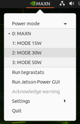
To switch the current power mode, click the NVIDIA icon to open a dropdown menu from the icon. Click “Power mode” to open a submenu of power modes:
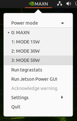
Click the power mode you want to set.
Note
GPU tpc_pg_mask can be set once before the GPU golden context is created.
If the nvpmodel power mode change requires to set the different tpc_pg_mask
value then the system reboot is required.
- Example:
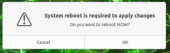
Press OK to do the system reboot.
To run
tegrastats, click the NVIDIA icon to open the dropdown menu: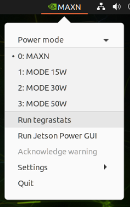
Click “Run tegrastats” to spawn a terminal window and run
tegrastats: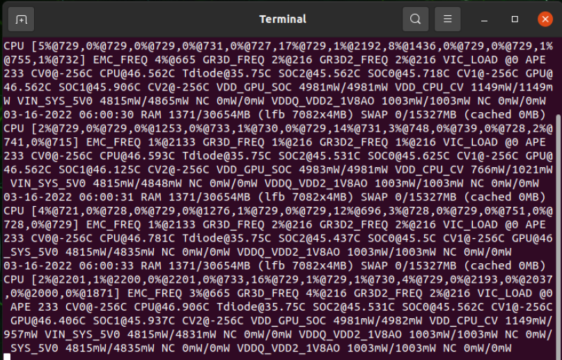
The
tegrastatsdisplay is described in Tegrastats Utility in the topic Jetson Linux Development Tools. It provides power-related information such as CPU, GPU, and EMC frequencies and the temperatures of thermal zones registered to the system.If system input voltage drops below a safe level, the
nvpmodelGUI displays a desktop notification to warn you that the system is being throttled back to avoid a shutdown due to insufficient power. When the system is thermally throttled, the GUI displays a similar notification to show that the device is operating at lowered speed to reduce heat generation.These are examples of notifications:


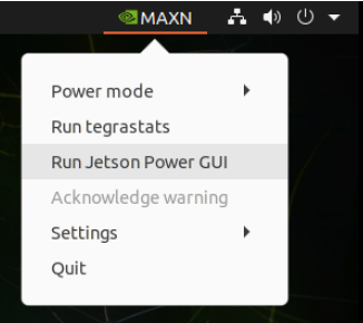
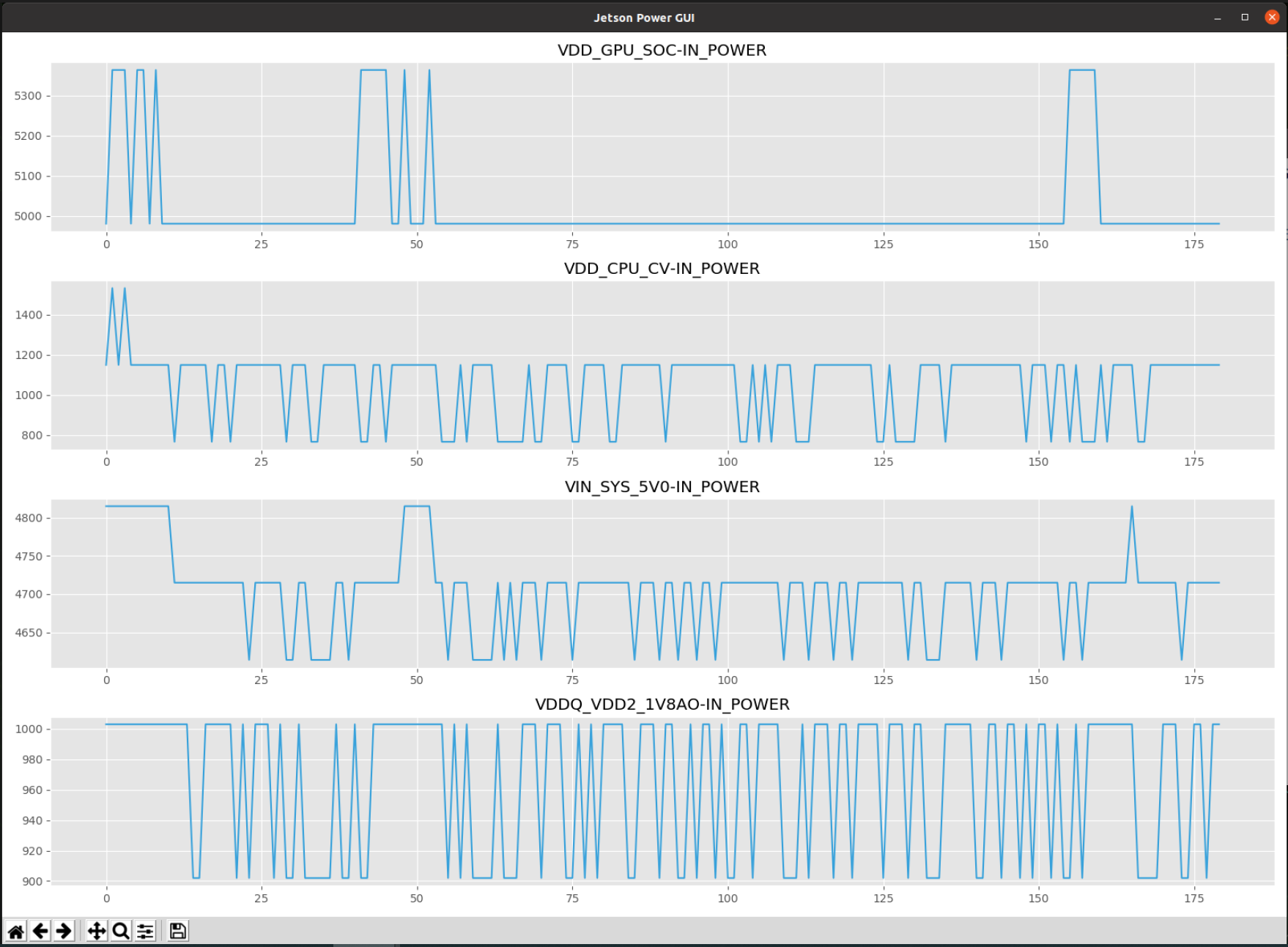
Jetson Power GUI
The Jetson Power GUI is a GUI tool for monitoring the power and thermal status of Jetson platforms. The tool reports various power and thermal related information which would help the user to understand power and thermal behavior of Jetson platforms.
To run
Jetson Power GUI:Click the nvpmodel GUI represented by an NVIDIA icon on the right side the Ubuntu desktop’s top bar.
Click the “Run Jetson Power GUI” submenu.
Main tab
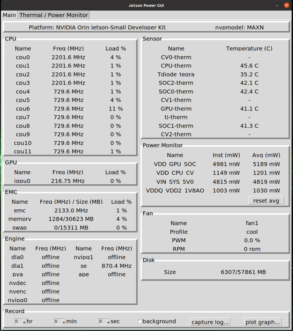
Here are the information / functionalities provided in the
Maintab:Frame name
Provided information / functionalities
Top
Jetson platform name
Current power mode
CPU
- CPU related information
State
Clock frequency
Load percentage
GPU
- GPU related information
State
Clock frequency
Load percentage
EMC
- EMC related information
State
Clock frequency
Load percentage
Memory usage (used size / total size)
Swap usage (used size / total size)
Engine
- Engine related information
State
Clock frequency
Sensor
- Thermal sensor related information
Temperature read by thermal sensor
Power Monitor
- Power monitor related information
Instantaneous power read by power monitor
Average power read by power monitor
- Power monitor related functionalities
Reset average power calculation by clicking the
"reset avg"button
Fan
- Fan related information
Fan profile
PWM percentage
RPM value
Disk
- Disk related information
Disk usage (used size / total size)
Record
- Functionalities
Allow the user to capture the log within the specified duration.
Click the “background” button to capture the log in the background, which avoids the system putting in extra effort on rendering GUI.
Allow the user to plot the power related data. The user can plot the data from captured log, or plot the real-time data.
Thermal / Power Monitor tab
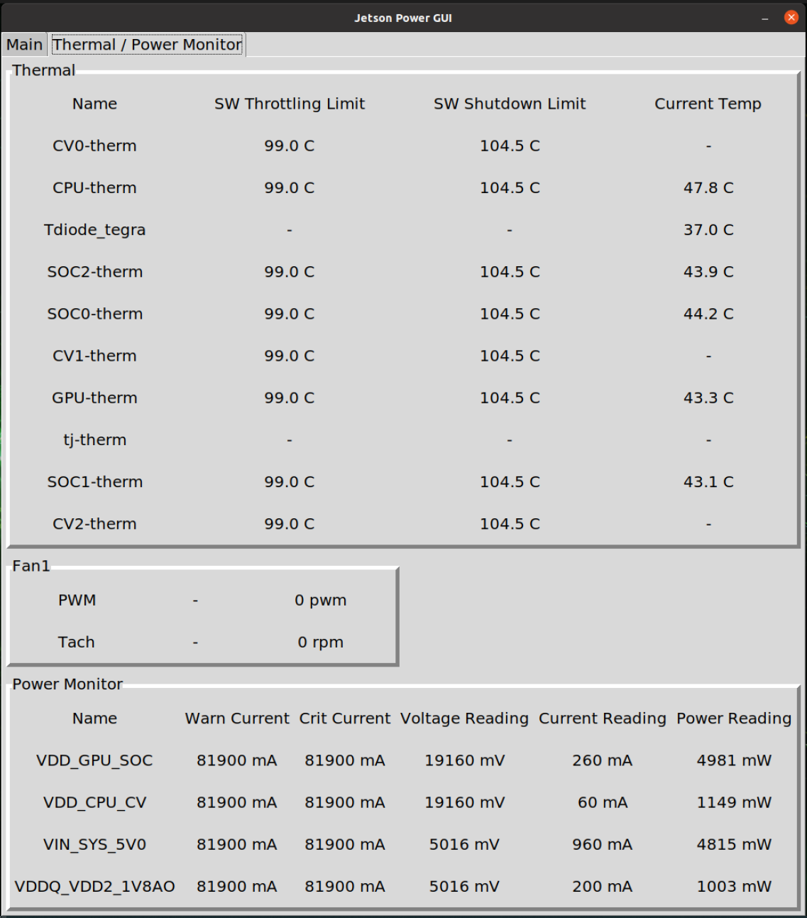
Here are the information / functionalities provided in the
Thermal / Power Monitortab:Frame name
Provided information / functionalities
Thermal
- Thermal sensor related information
Software throttling limit (if any)
Software shutdown limit (if any)
Temperature read by thermal sensor
Fan
- Fan related information
PWM value
RPM value
Power Monitor
- Power monitor related information
Average current limit
Instantaneous current limit
Voltage read by power monitor
Current read by power monitor
Power read by power monitor
Functionalities provided in Record frame
The Record frame provides these functionalities:
Capture power related information to a log file within the user specified duration
Plot the power related information to graph.
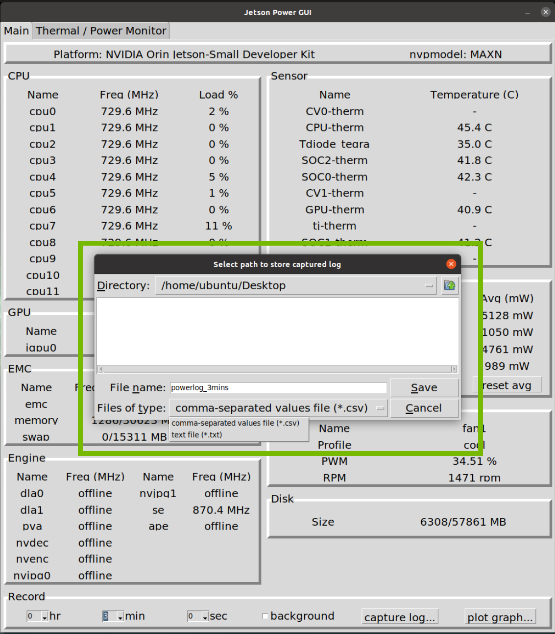
Below steps illustrate how to capture the data to a log file:
Before clicking the
"capture log..."button in the Record frame, please select the desired capture duration: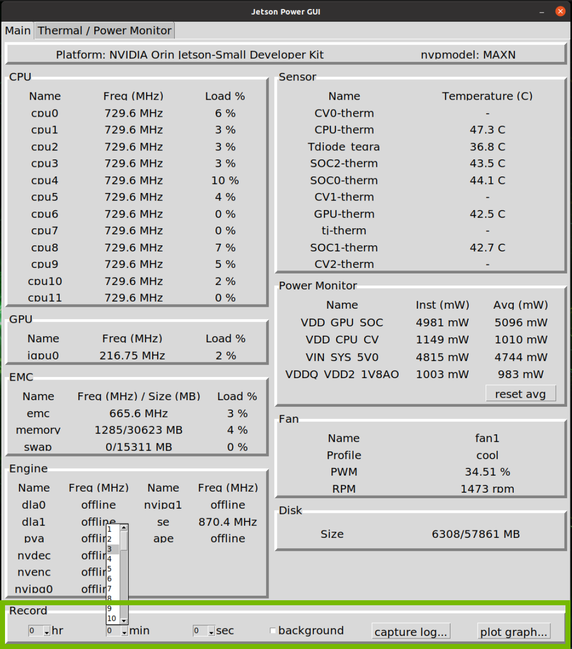
After selecting the desired capture duration, the user can click the
"capture log..."button, then a file dialog will be popped out to let the user select the path to save the captured log.There are two kinds of supported formats, the
.csvand the.txtfile format.If the user wants to capture the log in the background, the
"background"checkbox should be checked before clicking the"capture log..."button.
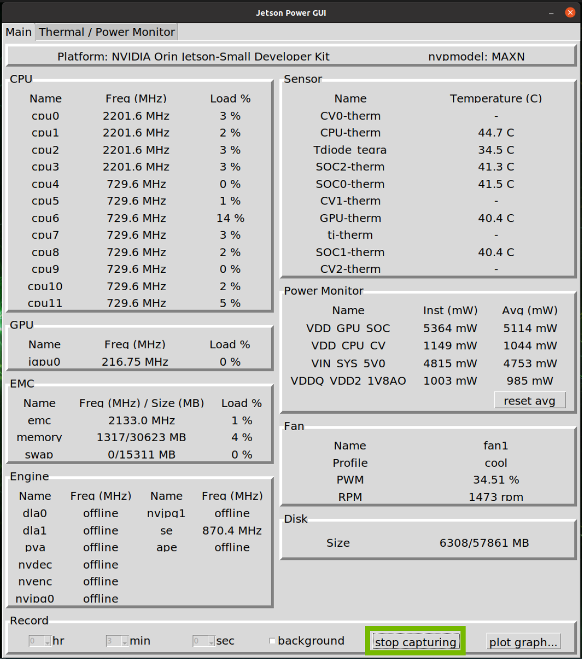
Once the path to save the captured log selected, the capturing process starts.
Note
If the user wants to stop the capturing process earlier during the capturing process, the user can click the
"stop capturing"button to interrupt the capturing process. The captured log will still be saved to the specified path.
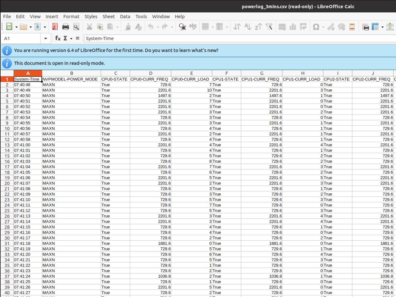
A message box will be popped out to notify the user once the capturing process finished.
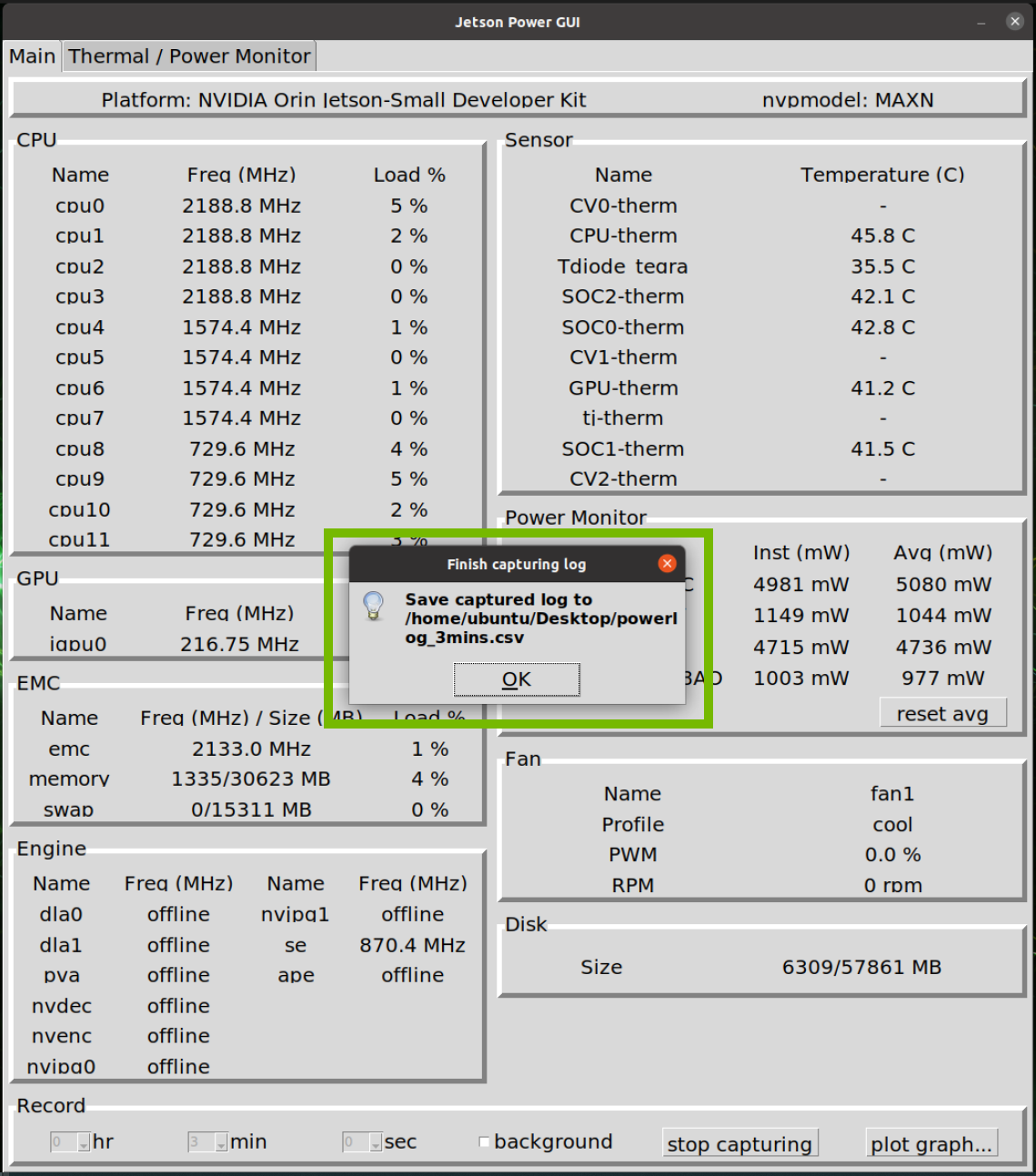
Here is the preview of the captured log.
Below steps illustrate how to visualize the data:
The
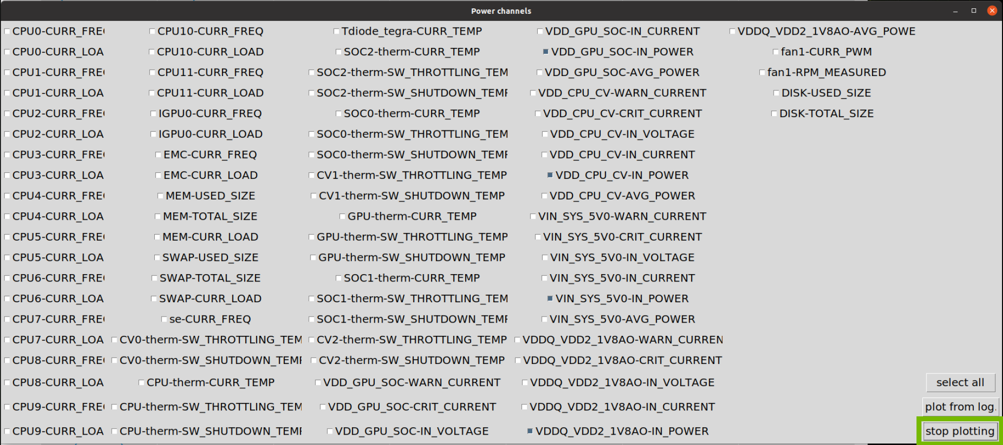
"plot graph..."button provides the data visualization functionality. Click the button to pop out a window which lets the user select the desired power channels to plot. Click the"select all"button to select all power channels with single click.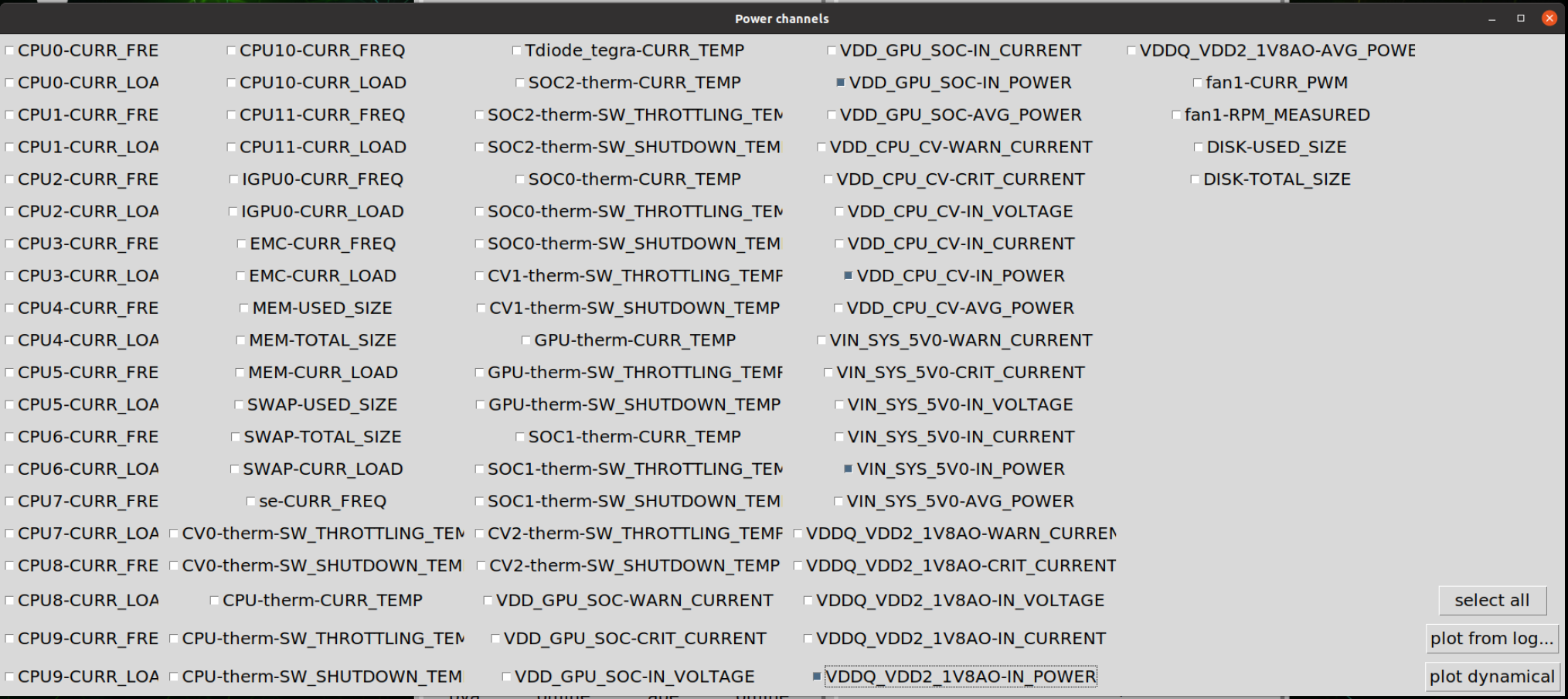
After selecting the desired power channels, the user can either plot the data from the captured log or in real time.
Clicking the
"plot from log..."button will pop out a file dialog, which lets the user choose which log file to plot.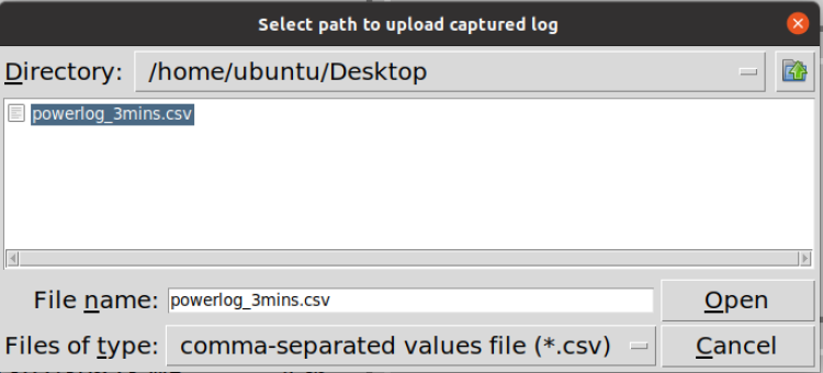
The data will be plotted once the log file is selected.
Clicking the
"plot dynamically"button will plot the last 120 seconds real-time data.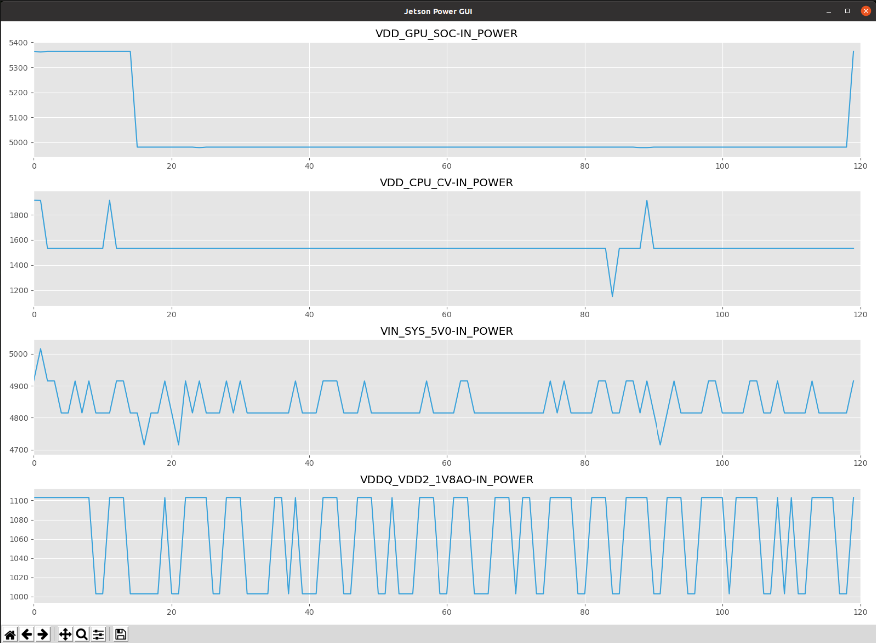
If the user wants to stop the real-time plotting process, the
"stop plotting"button can be clicked to stop.