Facebook Voyager Optical Interfaces
Facebook Voyager is a Broadcom Tomahawk-based switch with added Dense Wave Division Multiplexing (DWDM) ports that can connect to another switch thousands of kilometers away by adding transponders. DWDM allows many separate connections on one fiber pair by sending them over different wavelengths. Although the wavelengths are sent on the same physical fiber, they do not interact with each other, similar to VLANs on a trunk. Each wavelength can transport very high speeds over very long distances.
The Voyager Platform
The Voyager platform has 16 ports on the front of the switch:
- Twelve QSFP28 ethernet ports labeled 1 thru 12. These are
standard 100G ports that you configure like ports on other platforms
with a Tomahawk ASIC. The
ports.conffile defines the breakout configuration and the/etc/network/interfacesfile defines the other port parameters. When not broken out they are named swp1 thru swp12. - Four duplex LC ports labeled L1 thru L4. L1 and L2 connect to AC400 module 2. L3 and L4 connect to AC400 module 1. Each AC400 module connects to four Tomahawk ASIC ports.
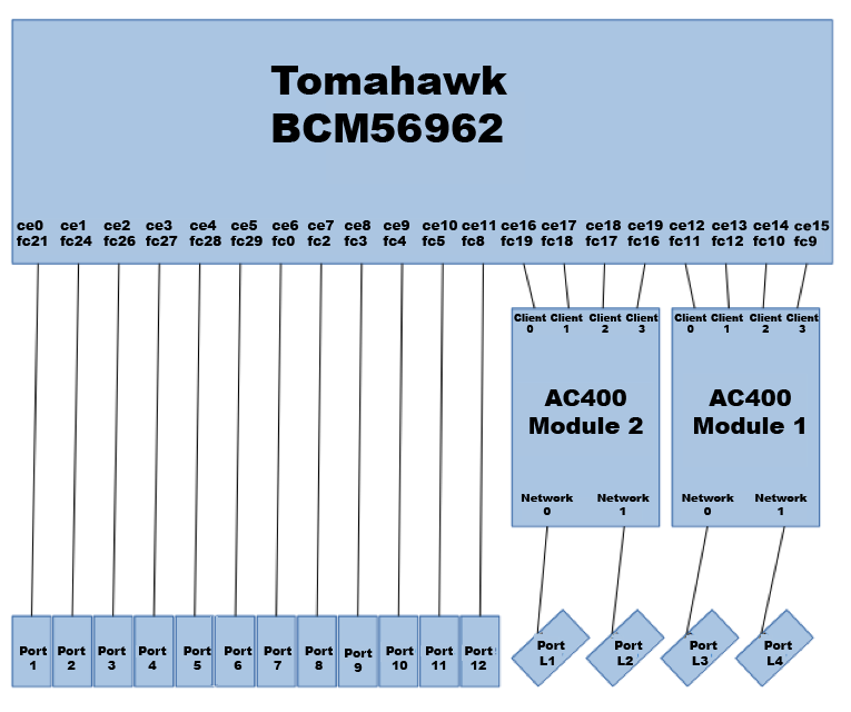
The fc designations on the Tomahawk stand for Falcon Core. Each AC400
module has four 100G interfaces connected to the Tomahawk and two
interfaces connected to the front of the box.
Inside the AC400
The way in which the client ports are mapped to the network ports in an AC400 depends on the modulation format and coupling mode. Cumulus Linux supports five different modulation and coupling mode options on each AC400 module.
| Network 0 Modulation | Network 1 Modulation | Independent/Coupled |
|---|---|---|
| QPSK | QPSK | Independent |
| 16-QAM | 16-QAM | Independent |
| QPSK | 16-QAM | Independent |
| 16-QAM | QPSK | Independent |
| 8-QAM | 8-QAM | Coupled |
QPSK-Quadrature phase shift keying. When a network interface is using QPSK modulation, it carries 100Gbps and is therefore connected to only one client interface.
16-QAM-Quadrature amplitude modulation with 4 bits per symbol. When a network interface is using 16-QAM modulation, it carries 200Gbps and is therefore connected to two client interfaces. Each of the two client interfaces carried on a network interface is called a tributary. The AC400 adds extra information so that these tributaries can be sorted out at the far end and delivered to the appropriate client interface.
8-QAM-Quadrature amplitude modulation with 3 bits per symbol. When a network interface is using 8-QAM modulation, it carries 150Gbps. In this case, the two network interfaces in an AC400 module must be coupled, so that the total bandwidth carried by the two interfaces is 300Gbps. Three client interfaces are used with this modulation format. However, unlike other modulation formats that use independent mode, the coupled mode means that data from each client interface is carried on both of the network interfaces.
Client to Network Connection
For each of the five supported modulation configurations, the client interface to network interface connections are as follows:
| Configuration | Connections |
|---|---|
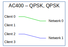 | In this configuration, two client interfaces, 0 and 2, are mapped to the two network interfaces. Client interfaces 1 and 3 are not used. |
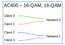 | In this configuration, two client interfaces are mapped to each network interface. Each network interface, therefore, has two tributaries. |
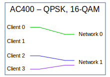 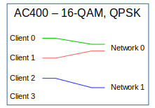 | These configurations are combinations of the previous two. The network interface configured for QPSK connects to one client interface and the network interface configured for 16-QAM connects to two client interfaces. |
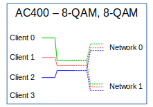 | This configuration uses three client interfaces, for a total of 300Gbps; 150Gbps on each network interface. Because the network interfaces are coupled, they cannot be connected to different far-end systems. Each network interface carries three tributaries. |
Configure the Voyager Ports
To configure the five modulation and coupling configurations described
above, edit the /etc/cumulus/ports.conf file. The ports do not exist
until you configure them.
The file has lines for the 12 QSPF28 ports. The four DWDM Line ports are labeled labeled L1 thru L4. To program the AC400 modulation and coupling into the five configurations, configure these ports as follows:
| ports.conf | L1 Modulation | L2 Modulation | Independent/Coupled |
|---|---|---|---|
| L1=1x L2=1x | QPSK | QPSK | Independent |
| L1=1x L2=2x | QPSK | 16-QAM | Independent |
| L1=2x L2=1x | 16-QAM | QPSK | Independent |
| L1=2x L2=2x | 16-QAM | 16-QAM | Independent |
| L1=3/2 L2=3/2 | 8-QAM | 8-QAM | Coupled |
The following example /etc/cumulus/ports.conf file shows configuration
for all of the modes.
1=1x    # Creates swp1
2=2x    # Creates swp2s0 and swp2s1
3=4x    # Creates four 25G ports: swp3s0, swp3s1, swp3s2, and swp3s3
4=1x40G # Creates swp4
5=4x10G # Creates four 10G ports: swp5s0, swp5s1, swp5s2, and swp5s3
6=1x
7=1x
8=1x
9=1x
10=1x
11=1x
12=1x
L1=2x   # Creates swpL1s0 and swpL1s1
L2=1x   # Creates swpL2
L3=3/2  # Creates swpL3s0, swpL3s1, and swpL3s2
L4=3/2  # Creates no "swpL4" ports since L4 is ganged with L3
Configure the Transponder Modules
The Voyager platform contains two AC400 transponder modules, which you configure with NCLU commands.
Many commands include the <trans-port> parameter. This is the network
interface of the transponder or the port, as printed on the front of the
system; L1, L2, L3, or L4.
Using NCLU commands is the preferred way to configure the transponder
modules. However, as an alternative, you can edit the
/etc/cumulus/transponders.ini file to make configuration changes. See
Edit the transponder.ini file
below.
Set the Transponder State
Each transponder module has a state, which is set to ready by default.
The available transponder states are listed below.
| Setting | Description |
|---|---|
reset | The module is in the reset state. The module cannot be accessed and remains non-operational until the state is changed to one of the other states. |
low-power | The module is in the low-power configuration state. The network interfaces are not powered up. This state can be used to configure the module before bringing it online. |
tx-off | The receivers and transmitters are turned up, but there is nothing being transmitted. |
ready | This is the fully operational state of the module. |
To change the state of the module, run the net add interface <trans-port> state (reset|low-power|tx-off|ready) command. For example,
to change the state of the transponder module to low power for L2, run
the following command:
cumulus@switch:~$ net add interface L2 state low-power
cumulus@switch:~$ net pending
cumulus@switch:~$ net commit
This command creates the following configuration snippet in the
/etc/cumulus/transponders.ini file:
cumulus@switch:~$ cat /etc/cumulus/transponders.ini
...
[AC400_2]
Location = 2
NetworkMode = independent
NetworkInterfaces = L1, L2
HostInterfaces = Host4, Host5, Host6, Host7
OperStatus = low_power
...
Use caution when changing the setting; although this command specifies a port, it affects an entire module. State changes on modules with multiple ports affect all ports on the module, not just the port specified.
Disable the Transmitter
You can disable or enable the transmitter of an individual network interface.
To disable the transmitter of a network interface, run the net add interface <trans-port> transmit-disable command. The following example
command disables the L1 transmitter:
cumulus@switch:~$ net add interface L1 transmit-disable
cumulus@switch:~$ net pending
cumulus@switch:~$ net commit
This command creates the following configuration snippet in the
/etc/cumulus/transponders.ini file:
cumulus@switch:~$ cat /etc/cumulus/transponders.ini
...
[L1]
Location = 0
TxEnable = false
...
To enable the transmitter of an individual network interface, run the
net del interface <trans-port> transmit-disable command. The following
example command enables the L1 transmitter:
cumulus@switch:~$ net del interface L1 transmit-disable
cumulus@switch:~$ net pending
cumulus@switch:~$ net commit
This command creates the following configuration snippet in the
/etc/cumulus/transponders.ini file:
cumulus@switch:~$ cat /etc/cumulus/transponders.ini
...
[L1]
Location = 0
TxEnable = true
...
Change the Grid Spacing
You can set grid spacing between two adjacent channels (the distance between channel frequencies) to 12.5GHz or 50GHz. The default spacing is 50 GHz.
To change the grid spacing, run the n``et add interface <trans-port> grid-spacing (12.5|50) command. The following command sets the grid
spacing on L2 to 12.5GHz:
cumulus@switch:~$ net add interface L2 grid-spacing 12.5
cumulus@switch:~$ net pending
cumulus@switch:~$ net commit
This command creates the following configuration snippet in the /etc/cumulus/transponders.ini
file:
cumulus@switch:~$ cat /etc/cumulus/transponders.ini
...
[L2]
Location = 1
TxEnable = true
TxGridSpacing = 12.5ghz
...
Set the Channel Frequency
To set the frequency used by the network interface, run the net add interface <trans-port> frequency <trans-frequency> command.
<trans-frequency> is a floating point number in THz. The transponders
support 100 channels, from 191.15 THz to 196.10 THz. Tab-completion is
supported on this command and shows the available frequencies, together
with the corresponding channel number and wavelength.
The following example command sets the frequency used by L2 to 195.30:
cumulus@switch:~$ net add interface L2 frequency 195.30
cumulus@switch:~$ net pending
cumulus@switch:~$ net commit
This command creates the following configuration snippet in the
/etc/cumulus/transponders.ini file:
cumulus@switch:~$ cat /etc/cumulus/transponders.ini
...
[L2]
Location = 1
TxEnable = true
TxGridSpacing = 50ghz
TxChannel = 84
...
The following example shows the command with the output when using tab completion:
cumulus@switch:~$ net add interface L1 frequency 195.<tab>
195.00 THz : Channel 78, Wavelength 1537.40 nm
195.05 THz : Channel 79, Wavelength 1537.00 nm
195.10 THz : Channel 80, Wavelength 1536.61 nm
195.15 THz : Channel 81, Wavelength 1536.22 nm
195.20 THz : Channel 82, Wavelength 1535.82 nm
195.25 THz : Channel 83, Wavelength 1535.43 nm
195.30 THz : Channel 84, Wavelength 1535.04 nm
195.35 THz : Channel 85, Wavelength 1534.64 nm
195.40 THz : Channel 86, Wavelength 1534.25 nm
195.45 THz : Channel 87, Wavelength 1533.86 nm
195.50 THz : Channel 88, Wavelength 1533.47 nm
195.55 THz : Channel 89, Wavelength 1533.07 nm
195.60 THz : Channel 90, Wavelength 1532.68 nm
195.65 THz : Channel 91, Wavelength 1532.29 nm
195.70 THz : Channel 92, Wavelength 1531.90 nm
195.75 THz : Channel 93, Wavelength 1531.51 nm
195.80 THz : Channel 94, Wavelength 1531.12 nm
195.85 THz : Channel 95, Wavelength 1530.72 nm
195.90 THz : Channel 96, Wavelength 1530.33 nm
195.95 THz : Channel 97, Wavelength 1529.94 nm
To see a complete list of the frequencies, channels, and wavelengths,
run the net show transponder frequency-map command (described in
Display Available Frequencies).
Set the Transmit Power
To set the amount of transmit power for a network interface, run the
net add interface <trans-port> power <trans-dBm> command.
<trans-dBm> is the power as a floating point number in units of dBm.
This value can range from -35.0 to 10.0. The following example command
sets the transmit power for L1 to 10.0 dBm.
cumulus@switch:~$ net add interface L1 power 10.0
cumulus@switch:~$ net pending
cumulus@switch:~$ net commit
This command creates the following configuration snippet in the /etc/cumulus/transponders.ini
file:
cumulus@switch:~$ cat /etc/cumulus/transponders.ini
...
[L1]
Location = 0
TxEnable = true
TxGridSpacing = 50ghz
TxChannel = 52
OutputPower = 10.0
...
Change the Modulation
To change the modulation technique used on a network interface, run the
net add interface <trans-port> modulation (16-qam|8-qam|pm-qpsk)
command. The available modulation options are 16-qam, 8-qam, and
pm-qpsk. The following example command changes the modulation on L1 to
8-qam:
cumulus@switch:~$ net add interface L1 modulation 8-qam
cumulus@switch:~$ net pending
cumulus@switch:~$ net commit
Changing the modulation also changes the Linux interfaces available in
the system, removing existing interfaces and adding the new ones.
Therefore, you must remove network interfaces with the net del interface swpLx... command before you change the modulation. The
network interfaces created for each modulation are as follows (L1 is
used as an example):
| Modulation | Linux Interfaces |
|---|---|
| 16-qam | swpL1s0 and swpL1s1 |
| 8-qam | swpL1s0, swpL1s1, and swpL1s2 |
| pm-qpsk | swpL1 |
Because 8-qam modulation requires both network interfaces on a module to
operate together, changing the modulation on one interface also changes
it on the other. Also, the network mode of the module changes
automatically to coupled when changing to 8-qam and reverts to
independent when leaving 8-qam modulation.
The only modulation format that allows the 15%_ac100 FEC mode is pm-qpsk. Attempting to change the modulation from pm-qpsk while 15%_ac100 FEC is configured is not allowed. First change the FEC mode to something other than 15%_ac100 and then the modulation.
Set the Differential Encoding
To select non-differential encoding on the network interface, run the
net add interface <trans-port> non-differential command. To revert to
differential encoding (the default), run the net del interface <trans-port> non-differential command. The following example command
selects non-differential encoding for L1:
cumulus@switch:~$ net add interface L1 non-differential
cumulus@switch:~$ net pending
cumulus@switch:~$ net commit
This command creates the following configuration snippet in the
/etc/cumulus/transponders.ini file:
cumulus@switch:~$ cat /etc/cumulus/transponders.ini
...
[L1]
Location = 0
TxEnable = true
TxGridSpacing = 50ghz
TxChannel = 52
OutputPower = 10.0
TxFineTuneFrequency = 0
MasterEnable = true
ModulationFormat = 16-qam
DifferentialEncoding = false
...
The following example command reverts to differential encoding (the default) for L1:
cumulus@switch:~$ net del interface L1 non-differential
cumulus@switch:~$ net pending
cumulus@switch:~$ net commit
This command creates the following configuration snippet in the
/etc/cumulus/transponders.ini file:
cumulus@switch:~$ cat /etc/cumulus/transponders.ini
...
[L1]
Location = 0
TxEnable = true
TxGridSpacing = 50ghz
TxChannel = 52
OutputPower = 10.0
TxFineTuneFrequency = 0
MasterEnable = true
ModulationFormat = 16-qam
DifferentialEncoding = true
...
Change Forward Error Correction
To select Forward Error Correction (FEC) mode, run the net add interface <trans-port> fec (15%|15%_ac100|25%) command. The available
modes are 15% (15% overhead SDFEC), 15%_ac100 (15% overhead SDFEC
compatible with AC100), and 25% ( 25% overhead SDFEC). The following
example command sets FEC mode on L1 to 15%:
cumulus@switch:~$ net add interface L1 fec 15%
cumulus@switch:~$ net pending
cumulus@switch:~$ net commit
This command creates the following configuration snippet in the
/etc/cumulus/transponders.ini file:
cumulus@switch:~$ cat /etc/cumulus/transponders.ini
...
[L1]
Location = 0
TxEnable = true
TxGridSpacing = 50ghz
TxChannel = 52
OutputPower = 10.0
TxFineTuneFrequency = 0
MasterEnable = true
ModulationFormat = 16-qam
DifferentialEncoding = true
FecMode = 15%
...
Configure a Line Side Loopback
Line side loopback mode enables you to send and receive data from the same network interface port to verify that the port is operational.
To enable line side loopback mode, run the net add interface <interface> facility-loopback command. You can enable line side loopback mode on one or
multiple interfaces. The following example enables loopback mode
on the L1, L2, L3, and L4 network interfaces:
cumulus@switch:~$ net add interface L1-4 facility-loopback
cumulus@switch:~$ net pending
cumulus@switch:~$ net commit
To disable loopback mode, run the net del interface <interface> facility-loopback command. The following example disables loopback mode
on the L1, L2, L3, and L4 network interfaces:
cumulus@switch:~$ net del interface L1-4 facility-loopback
cumulus@switch:~$ net pending
cumulus@switch:~$ net commit
To enable loopback on the client interface (internal loopback for DWDM
testing), edit the /etc/cumulus/transponders.ini file. See
Edit the transponders.ini file below.
Display the Transponder Status
To display the current status of the transponder module, run the net show transponder command. The first two lines of command output
displays the status of the module and the next section displays the
status of the network interfaces. This is repeated for each module in
the system.
cumulus@switch:~$ net show transponder
Module: 1 ready Acacia Comm Inc. AC400-004-330 S/N:170212599 53.88C 11.89V
    Laser: 191.15 THz - 196.10 THz, 6.00 GHz fine tune, independent lanes

                                            Network Interfaces
                                      L3                           L4
                        ---------------------------  ---------------------------
            Modulation 16-qam                       16-qam
              Frequency 193.70 THz, Channel 52      193.70 THz, Channel 52
            Current BER 1.428e-04                   1.387e-05
          Current OSNR 84.90dBm                     84.80dBm
Current Chromatic Disp 13ps/nm                      9ps/nm
            TX/RX Power 0.99dBm/0.66dBm             1.00dBm/0.43dBm
              Encoding differential                 differential
              Alignment TX & RX                     TX & RX
          Grid Spacing 50ghz                        50ghz
              FEC Mode 25%                          25%
Uncorrectable FEC Errs 0                            0
          TX/RX Turn-up power_adjusted/locked       power_adjusted/locked

Module: 2 ready Acacia Comm Inc. AC400-004-330 S/N:170212585 55.00C 11.90V
    Laser: 191.15 THz - 196.10 THz, 6.00 GHz fine tune, independent lanes

                                            Network Interfaces
                                      L1                           L2
                        ---------------------------  ---------------------------
                Modulation 16-qam                       16-qam
                 Frequency 193.70 THz, Channel 52       193.70 THz, Channel 52
               Current BER 7.039e-05                    7.404e-05
              Current OSNR 84.90dBm                     84.80dBm
    Current Chromatic Disp 13ps/nm                      9ps/nm
               TX/RX Power 0.98dBm/0.48dBm              0.99dBm/-0.78dBm
                  Encoding differential                 differential
                 Alignment TX & RX                      TX & RX
              Grid Spacing 50ghz                        50ghz
                  FEC Mode 25%                          25%
    Uncorrectable FEC Errs 0                            0
             TX/RX Turn-up power_adjusted/locked        power_adjusted/locked
To display only the status of a particular module, use the module <trans-module> option, which specifies the transponder module number.
The following example command displays the status of transponder module
1:
cumulus@switch:~$ net show transponder module 1
Module: 1 ready Acacia Comm Inc. AC400-004-330 S/N:170212599 53.75C 11.89V
    Laser: 191.15 THz - 196.10 THz, 6.00 GHz fine tune, independent lanes

                                           Network Interfaces
                                     L3                           L4
                       ---------------------------  ---------------------------
            Modulation 16-qam                       16-qam
             Frequency 193.70 THz, Channel 52       193.70 THz, Channel 52
           Current BER 1.626e-04                    1.343e-05
          Current OSNR 84.90dBm                     84.80dBm
Current Chromatic Disp 13ps/nm                      9ps/nm
           TX/RX Power 1.00dBm/0.67dBm              0.99dBm/0.42dBm
              Encoding differential                 differential
             Alignment TX & RX                      TX & RX
          Grid Spacing 50ghz                        50ghz
              FEC Mode 25%                          25%
Uncorrectable FEC Errs 0                            0
         TX/RX Turn-up power_adjusted/locked        power_adjusted/locked
To display more information, including the host interfaces, use the
verbose option. The following example command displays more
information about the transponder module:
cumulus@switch:~$ net show transponder module 1 verbose
To display all status information in JSON format, use the json option.
The following example command displays all status information in JSON
format:
cumulus@switch:~$ net show transponder json
{
    "modules" : [
        {
            "location" : "1",
            "vendor_name" : "Acacia Comm Inc.",
            "part_num" : "AC400-004-330",
            "serial_num" : "170212599",
            "fw_version_a" : 17.100000,
            "fw_version_b" : 17.100000,
            "min_laser_freq" : 191150000000000,
            "max_laser_freq" : 196100000000000,
            "fine_tune_freq" : 6000000000,
            "grid_support" : [ "50ghz", "12.5ghz" ],
            "max_channels" : 100,
            "oper_status" : "ready",
            "internal_temp" : 53.625000,
            "supply_voltage" : 11.903000,
            "num_host_ifs" : 4,
            "num_net_ifs" : 2,
            "net_mode" : "independent",
            "host_interfaces" : [
                {
                    "index" : 0,
                    "lane_fault_status" : [
                        [ "no_faults" ],
                        [ "no_faults" ],
                        [ "no_faults" ],
                        [ "no_faults" ]
                    ],
                    "tx_align_status" : [ "aligned" ],
                    "rate" : "100ge",
                    "enabled" : true,
                    "fec_decoding" : false,
                    "fec_encoding" : false,
                    "tx_reset" : false,
                    "rx_reset" : false,
                    "deserializer" : [ 1, 18, 0 ],
                    "serializer" : [ 3, 3, 6, 12, 6 ],
                    "indep_tributary" : 0,
                    "coupled_tributary" : 0,
                    "loopback" : false
                },
...
Display Available Channel Frequencies
To display a map of available channel frequencies, numbers, and
wavelengths, run the net show transponder frequency-map [json]
command.
The following example command displays a map of available channel frequencies, numbers, and wavelengths.
cumulus@switch:~$ net show transponder frequency-map
Frequency   Channel   Wavelength
  (THz)       (#)        (nm)
---------   -------   ----------
 191.15        1       1568.36
 191.20        2       1567.95
 191.25        3       1567.54
 191.30        4       1567.13
 191.35        5       1566.72
 191.40        6       1566.31
 191.45        7       1565.90
 191.50        8       1565.50
 191.55        9       1565.09
 191.60       10       1564.68
 191.65       11       1564.27
 191.70       12       1563.86
 191.75       13       1563.45
 191.80       14       1563.05
 191.85       15       1562.64
...
The following example command displays a map of available channel frequencies, numbers, and wavelengths in JSON format.
cumulus@switch:~$ net show transponder frequency-map json
[
    [
        1,
        191.15,
        1568.36
    ],
    [
        2,
        191.2,
        1567.95
    ],
    [
        3,
        191.25,
        1567.54
    ],
    [
        4,
        191.3,
        1567.13
    ],
...
Display the Current Transponder Configuration
To display the current configuration state of the transponders, run the following command:
cumulus@switch:~$ net show configuration transponders

transponders

  AC400_1

    Location
      1

    NetworkMode
      independent

    L3

      Location
        0

      TxEnable
        true

      TxGridSpacing
        50ghz

      TxChannel
        52

      OutputPower
        1

      TxFineTuneFrequency
        0

      MasterEnable
        true

      ModulationFormat
        16-qam

      DifferentialEncoding
        true

      FecMode
        25%

      Loopback
        false

      TxTributaryIndependent
        0
        1

      TxTributaryCoupled
        0
        1
        2
        15
...
Edit the transponders.ini File
As an alternative to using NCLU commands to configure the transponder
modules (described above), you can edit the
/etc/cumulus/transponders.ini file, then Initiate a hardware update.
Using NCLU commands to configure the transponder modules is the
preferred method. However, not all configuration options are available
with NCLU. If you want to change a transponder module configuration
setting that does not have an NCLU command, you can change the setting
manually in the transponders.ini file, then initiate the hardware
update. Use caution when editing the /etc/cumulus/transponders.ini
file.
The /etc/cumulus/transponders.ini file consists of groups of key-value
pairs, interspersed with comments. Configuration groups start with a
header line that contains the group name enclosed in square brackets ([
]) and end implicitly by the start of the next group or the end of the
file. Key-value pairs have the form key=value. Spaces before and after
the = character are ignored. Lines beginning with # and blank lines are
considered comments.
Here is an example /etc/cumulus/transponders.ini file:
#
# Configuration file for Voyager transponder modules
#
[Modules]
Names=AC400_1,AC400_2

[AC400_1]
Location=1
NetworkMode=independent
NetworkInterfaces=L3,L4
HostInterfaces=Client0,Client1,Client2,Client3
OperStatus=ready

[AC400_2]
Location=2
NetworkMode=independent
NetworkInterfaces=L1,L2
HostInterfaces=Client4,Client5,Client6,Client7
OperStatus=ready

[L1]
Location=0
TxEnable=true
TxGridSpacing=50ghz
TxChannel=52
OutputPower=1
TxFineTuneFrequency=0
MasterEnable=true
ModulationFormat=16-qam
DifferentialEncoding=true
FecMode=25%
TxTributaryIndependent=0,1
TxTributaryCoupled=0,1,2,15
Loopback=false

[L2]
Location=1
TxEnable=true
TxGridSpacing=50ghz
TxChannel=52
OutputPower=1
TxFineTuneFrequency=0
MasterEnable=true
ModulationFormat=16-qam
DifferentialEncoding=true
FecMode=25%
TxTributaryIndependent=2,3
TxTributaryCoupled=0,1,2,15
Loopback=false

[L3]
Location=0
TxEnable=true
TxGridSpacing=50ghz
TxChannel=52
OutputPower=1
TxFineTuneFrequency=0
MasterEnable=true
ModulationFormat=16-qam
DifferentialEncoding=true
FecMode=25%
TxTributaryIndependent=0,1
TxTributaryCoupled=0,1,2,15
Loopback=false

[L4]
Location=1
TxEnable=true
TxGridSpacing=50ghz
TxChannel=52
OutputPower=1
TxFineTuneFrequency=0
MasterEnable=true
ModulationFormat=16-qam
DifferentialEncoding=true
FecMode=25%
TxTributaryIndependent=2,3
TxTributaryCoupled=0,1,2,15
Loopback=false

[Client0]
Location=0
Rate=100ge
Enable=true
FecDecoder=false
FecEncoder=false
DeserialLfCtleGain=1
DeserialCtleGain=18
DeserialDfeCoeff=0
SerialTap0Gain=3
SerialTap0Delay=3
SerialTap1Gain=6
SerialTap2Gain=12
SerialTap2Delay=6
RxTributaryIndependent=0
RxTributaryCoupled=0
Loopback=false

[Client1]
Location=1
Rate=100ge
Enable=true
FecDecoder=false
FecEncoder=false
DeserialLfCtleGain=1
DeserialCtleGain=18
DeserialDfeCoeff=0
SerialTap0Gain=3
SerialTap0Delay=3
SerialTap1Gain=6
SerialTap2Gain=12
SerialTap2Delay=6
RxTributaryIndependent=1
RxTributaryCoupled=1
Loopback=false

[Client2]
Location=2
Rate=100ge
Enable=true
FecDecoder=false
FecEncoder=false
DeserialLfCtleGain=1
DeserialCtleGain=18
DeserialDfeCoeff=0
SerialTap0Gain=3
SerialTap0Delay=3
SerialTap1Gain=6
SerialTap2Gain=12
SerialTap2Delay=6
RxTributaryIndependent=2
RxTributaryCoupled=2
Loopback=false

[Client3]
Location=3
Rate=100ge
Enable=true
FecDecoder=false
FecEncoder=false
DeserialLfCtleGain=1
DeserialCtleGain=18
DeserialDfeCoeff=0
SerialTap0Gain=3
SerialTap0Delay=3
SerialTap1Gain=6
SerialTap2Gain=12
SerialTap2Delay=6
RxTributaryIndependent=3
RxTributaryCoupled=65535
Loopback=false

[Client4]
Location=0
Rate=100ge
Enable=true
FecDecoder=false
FecEncoder=false
DeserialLfCtleGain=1
DeserialCtleGain=18
DeserialDfeCoeff=0
SerialTap0Gain=3
SerialTap0Delay=3
SerialTap1Gain=5
SerialTap2Gain=9
SerialTap2Delay=5
RxTributaryIndependent=0
RxTributaryCoupled=0
Loopback=false

[Client5]
Location=1
Rate=100ge
Enable=true
FecDecoder=false
FecEncoder=false
DeserialLfCtleGain=1
DeserialCtleGain=18
DeserialDfeCoeff=0
SerialTap0Gain=3
SerialTap0Delay=3
SerialTap1Gain=5
SerialTap2Gain=9
SerialTap2Delay=5
RxTributaryIndependent=1
RxTributaryCoupled=1
Loopback=false

[Client6]
Location=2
Rate=100ge
Enable=true
FecDecoder=false
FecEncoder=false
DeserialLfCtleGain=1
DeserialCtleGain=18
DeserialDfeCoeff=0
SerialTap0Gain=3
SerialTap0Delay=3
SerialTap1Gain=5
SerialTap2Gain=9
SerialTap2Delay=5
RxTributaryIndependent=2
RxTributaryCoupled=2
Loopback=false

[Client7]
Location=3
Rate=100ge
Enable=true
FecDecoder=false
FecEncoder=false
DeserialLfCtleGain=1
DeserialCtleGain=18
DeserialDfeCoeff=0
SerialTap0Gain=3
SerialTap0Delay=3
SerialTap1Gain=5
SerialTap2Gain=9
SerialTap2Delay=5
RxTributaryIndependent=3
RxTributaryCoupled=65535
Loopback=false
The file contains four configuration groups:
- The Modules group
- The module groups
- The network interface groups
- The client interface groups
Modules Group
The Modules group identifies the names of the other groups in
the file. This is the root group from which all other groups are
referenced; it must always be the first group in the file and must be
named Modules.
There is only one key-value pair in this group. Each value in the list represents a transponder in the system. There must be a group within the file that has the same name as each value in the list.
The following example shows that there are two modules in the system
named AC400_1 and AC400_2. The transponders.ini file must contain
these two groups.
[Modules]
Names=AC400_1,AC400_2
Module Groups
The module groups are individual groups for each of the predefined modules
and define the attributes of the transponders in the system. The name of a module group
is defined in the values of the Names key in the Modules group (shown
above).
The following table describes the key-value pairs in the module groups.
Key | Value Type | Description |
|---|---|---|
| Integer: 1 or 2 | The location or identifier of the module within Voyager. Voyager has two modules which are identified by indexes 1 and 2.
|
| String: | The overall mode of the two network interfaces on the module:
The default value is Note: When network interfaces are configured in 8-qam mode, you must set this key to |
| Comma-separated list of network interface group names | Each value in the list represents a network interface connected to this module. There must be a group within the file that has the same name as each value in the list. Network interfaces are the module interfaces that leave the Voyager platform and are labeled L1, L2, L3, and L4 on the front of the Voyager. Note: Although you can use any string for the network interface group names, it is best to use the labels on the front of the Voyager to avoid confusion. |
| Comma-separated list of client interface group names | Each value in this list represents a client interface connected to this module. There must be a group within the file that has the same name as each value in the list. Client interfaces are the module interfaces that connect to the Tomahawk switching ASIC. |
| String: | The operational status of the module:
|
The following example provides the configuration for module 1. The
network interfaces are configured to operate independently and are
defined in the L3 and L4 groups in the file. The client interfaces
are defined in the Client0, Client1, Client2, and Client3 groups in the
file. The operational status of the module is ready.
[AC400_1]
Location=1
NetworkMode=independent
NetworkInterfaces=L3,L4
HostInterfaces=Client0,Client1,Client2,Client3
OperStatus=ready
Network Interface Groups
The network interface groups define the attributes of the network
interfaces on the module. The name of a network interface group is
defined in the values of the NetworkInterfaces key in the module
groups.
The following table describes the key-value pairs in the network interface groups.
Key | Value Type | Description | |||||||||||||||||||||||||||||||||||||||||||||||||||||||||||||||||||||||||||||||||||||||||||||||||||||||||||||||||||||||||||||||||||||||||||||||||||||||||||||||||||||||||||||||||||||||||||||||||||||||||||||||||||||||||||||||||||||||||||||||||||||||||||||||||||||||||||||||||||||||||||||||||||||||||||||||
|---|---|---|---|---|---|---|---|---|---|---|---|---|---|---|---|---|---|---|---|---|---|---|---|---|---|---|---|---|---|---|---|---|---|---|---|---|---|---|---|---|---|---|---|---|---|---|---|---|---|---|---|---|---|---|---|---|---|---|---|---|---|---|---|---|---|---|---|---|---|---|---|---|---|---|---|---|---|---|---|---|---|---|---|---|---|---|---|---|---|---|---|---|---|---|---|---|---|---|---|---|---|---|---|---|---|---|---|---|---|---|---|---|---|---|---|---|---|---|---|---|---|---|---|---|---|---|---|---|---|---|---|---|---|---|---|---|---|---|---|---|---|---|---|---|---|---|---|---|---|---|---|---|---|---|---|---|---|---|---|---|---|---|---|---|---|---|---|---|---|---|---|---|---|---|---|---|---|---|---|---|---|---|---|---|---|---|---|---|---|---|---|---|---|---|---|---|---|---|---|---|---|---|---|---|---|---|---|---|---|---|---|---|---|---|---|---|---|---|---|---|---|---|---|---|---|---|---|---|---|---|---|---|---|---|---|---|---|---|---|---|---|---|---|---|---|---|---|---|---|---|---|---|---|---|---|---|---|---|---|---|---|---|---|---|---|---|---|---|---|---|---|---|---|---|---|---|---|---|---|---|---|---|---|---|---|---|---|---|---|---|---|---|---|---|---|---|---|---|---|---|---|---|---|---|---|
| Integer: 0-1 | The location or index of the network interface within a module. The Voyager AC400 modules each have two network interfaces that are connected to the external ports as follows:
| |||||||||||||||||||||||||||||||||||||||||||||||||||||||||||||||||||||||||||||||||||||||||||||||||||||||||||||||||||||||||||||||||||||||||||||||||||||||||||||||||||||||||||||||||||||||||||||||||||||||||||||||||||||||||||||||||||||||||||||||||||||||||||||||||||||||||||||||||||||||||||||||||||||||||||||||
| Boolean: | Enable ( | |||||||||||||||||||||||||||||||||||||||||||||||||||||||||||||||||||||||||||||||||||||||||||||||||||||||||||||||||||||||||||||||||||||||||||||||||||||||||||||||||||||||||||||||||||||||||||||||||||||||||||||||||||||||||||||||||||||||||||||||||||||||||||||||||||||||||||||||||||||||||||||||||||||||||||||||
| String: | Defines the channel spacing. The AC400 does not support variable-width channels; only different channel center frequencies. The default is | |||||||||||||||||||||||||||||||||||||||||||||||||||||||||||||||||||||||||||||||||||||||||||||||||||||||||||||||||||||||||||||||||||||||||||||||||||||||||||||||||||||||||||||||||||||||||||||||||||||||||||||||||||||||||||||||||||||||||||||||||||||||||||||||||||||||||||||||||||||||||||||||||||||||||||||||
| Integer: 1-100 | The channel number upon which the network interface transmits and receives data. Click here to see the frequency and wavelength per channel
| |||||||||||||||||||||||||||||||||||||||||||||||||||||||||||||||||||||||||||||||||||||||||||||||||||||||||||||||||||||||||||||||||||||||||||||||||||||||||||||||||||||||||||||||||||||||||||||||||||||||||||||||||||||||||||||||||||||||||||||||||||||||||||||||||||||||||||||||||||||||||||||||||||||||||||||||
| Floating point number: | The output power of the network interface in dBm. | |||||||||||||||||||||||||||||||||||||||||||||||||||||||||||||||||||||||||||||||||||||||||||||||||||||||||||||||||||||||||||||||||||||||||||||||||||||||||||||||||||||||||||||||||||||||||||||||||||||||||||||||||||||||||||||||||||||||||||||||||||||||||||||||||||||||||||||||||||||||||||||||||||||||||||||||
| Integer | The fine tune frequency of the laser in units of 1 Hz. The AC400 modules on Voyager are only capable of 1 MHz resolution; you must specify this value in multiples of 1,000,000. The default value is 0. | |||||||||||||||||||||||||||||||||||||||||||||||||||||||||||||||||||||||||||||||||||||||||||||||||||||||||||||||||||||||||||||||||||||||||||||||||||||||||||||||||||||||||||||||||||||||||||||||||||||||||||||||||||||||||||||||||||||||||||||||||||||||||||||||||||||||||||||||||||||||||||||||||||||||||||||||
| Boolean: | Enables ( | |||||||||||||||||||||||||||||||||||||||||||||||||||||||||||||||||||||||||||||||||||||||||||||||||||||||||||||||||||||||||||||||||||||||||||||||||||||||||||||||||||||||||||||||||||||||||||||||||||||||||||||||||||||||||||||||||||||||||||||||||||||||||||||||||||||||||||||||||||||||||||||||||||||||||||||||
| String: | Defines the modulation format used on the network interface:
Note: When selecting | |||||||||||||||||||||||||||||||||||||||||||||||||||||||||||||||||||||||||||||||||||||||||||||||||||||||||||||||||||||||||||||||||||||||||||||||||||||||||||||||||||||||||||||||||||||||||||||||||||||||||||||||||||||||||||||||||||||||||||||||||||||||||||||||||||||||||||||||||||||||||||||||||||||||||||||||
| Boolean: | Enables ( | |||||||||||||||||||||||||||||||||||||||||||||||||||||||||||||||||||||||||||||||||||||||||||||||||||||||||||||||||||||||||||||||||||||||||||||||||||||||||||||||||||||||||||||||||||||||||||||||||||||||||||||||||||||||||||||||||||||||||||||||||||||||||||||||||||||||||||||||||||||||||||||||||||||||||||||||
| String: | Selects the type of forward error correction used on the network interface.
| |||||||||||||||||||||||||||||||||||||||||||||||||||||||||||||||||||||||||||||||||||||||||||||||||||||||||||||||||||||||||||||||||||||||||||||||||||||||||||||||||||||||||||||||||||||||||||||||||||||||||||||||||||||||||||||||||||||||||||||||||||||||||||||||||||||||||||||||||||||||||||||||||||||||||||||||
| List of two comma-separated integers | Defines which client interfaces map to this network interface when Note: Do not change this value. The Tomahawk switching ASIC should be configured to steer data to the appropriate network interface, not this attribute. | |||||||||||||||||||||||||||||||||||||||||||||||||||||||||||||||||||||||||||||||||||||||||||||||||||||||||||||||||||||||||||||||||||||||||||||||||||||||||||||||||||||||||||||||||||||||||||||||||||||||||||||||||||||||||||||||||||||||||||||||||||||||||||||||||||||||||||||||||||||||||||||||||||||||||||||||
| List of four comma-separated integers | Defines which client interfaces map to this network interface when Note: Do not change this value. The Tomahawk switching ASIC should be configured to steer data to the appropriate network interface, not this attribute. | |||||||||||||||||||||||||||||||||||||||||||||||||||||||||||||||||||||||||||||||||||||||||||||||||||||||||||||||||||||||||||||||||||||||||||||||||||||||||||||||||||||||||||||||||||||||||||||||||||||||||||||||||||||||||||||||||||||||||||||||||||||||||||||||||||||||||||||||||||||||||||||||||||||||||||||||
| Boolean: | Enables ( |
The following example shows a network interface at location 0, which
has transmission enabled and 50ghz channel spacing. Communication occurs
on channel 52 with 1dBm of power. The network interface becomes
operational when leaving the low power state. 16-qam encoding is used
(200G) with differential encoding and 25% overhead SDFEC. The tributary
mappings of the client interfaces is left unchanged. Loopback mode is
disabled.
[L1]
Location=0
TxEnable=true
TxGridSpacing=50ghz
TxChannel=52
OutputPower=1
TxFineTuneFrequency=0
MasterEnable=true
ModulationFormat=16-qam
DifferentialEncoding=true
FecMode=25%
TxTributaryIndependent=0,1
TxTributaryCoupled=0,1,2,15
Loopback=false
Client Interface Groups
The client interface groups define the attributes of the client
interfaces on the module. The name of a client interface group is
defined in the values of the HostInterfaces key of the module group.
The following table describes the key-value pairs in the client interface groups.
Because client interfaces are internal interfaces between the transponder module and the Tomahawk switching ASIC, the default values of these attributes do not typically need to be changed.
| Key | Value Type | Description | |||||||||||||||||||||||||||
|---|---|---|---|---|---|---|---|---|---|---|---|---|---|---|---|---|---|---|---|---|---|---|---|---|---|---|---|---|---|
Location | Integer: 0-3 | The location or index of the client interface within a module. The Voyager AC400 modules each have four network interfaces that are connected to the Tomahawk ASIC as follows:
| |||||||||||||||||||||||||||
Rate | String: otu4 or `100ge`` | The rate at which the client interface operates. Because the client interfaces on Voyager are always connected to a Tomahawk ASIC, always set this value to 100ge. | |||||||||||||||||||||||||||
Enable | Boolean: true or false | Enables (true) or disables (false) the client interface. | |||||||||||||||||||||||||||
FecDecoder | Boolean: true or false | Enables (true) or disables (false)FEC decoding for data received from the Tomahawk switching ASIC. | |||||||||||||||||||||||||||
FecEncoder | Boolean: true or false | Enables (true) or disables (false) FEC encoding for data sent to the Tomahawk switching ASIC. | |||||||||||||||||||||||||||
DeserialLfCtleGain | Integer: 0-8 | These attributes configure the SERDES of the client interface. The values for these attributes have been carefully determined by hardware engineers; do not change them. | |||||||||||||||||||||||||||
DeserialCtleGain | Integer: 0-20 | ||||||||||||||||||||||||||||
DeserialDfeCoeff | Integer: 0-63 | ||||||||||||||||||||||||||||
SerialTap0Gain | Integer: 0-7 | ||||||||||||||||||||||||||||
SerialTap0Delay | Integer: 0-7 | ||||||||||||||||||||||||||||
SerialTap1Gain | Integer: 0-7 | ||||||||||||||||||||||||||||
SerialTap2Gain | Integer: 0-15 | ||||||||||||||||||||||||||||
SerialTap2Delay | Integer: 0-7 | ||||||||||||||||||||||||||||
RxTributaryIndependent | Integer: 0-1 | Defines which network interface maps to this client interface when NetworkMode for the client interface is set to independent. The integer is the Location value of the network interface.Note: Do not change this value. The Tomahawk switching ASIC should be configured to steer data from the appropriate network interface, not this attribute. | |||||||||||||||||||||||||||
RxTributaryCoupled | Integer: 0-1 | Defines which network interface maps to this client interface when NetworkMode for the client interface is set to coupled. The integer is the Location value of the network interface.Note: Do not change this value. The Tomahawk switching ASIC should be configured to steer data from the appropriate network interface, not this attribute. | |||||||||||||||||||||||||||
Loopback | Boolean: true or false | Enables (true) or disables (false) terminal loopback mode on a client interface. When enabled, you send and receive data from the same client interface port to verify that the port is operational. This is useful for DWDM testing. |
The following example shows a sample configuration for a client interface group.
[Client0]
Location=0
Rate=100ge
Enable=true
FecDecoder=false
FecEncoder=false
DeserialLfCtleGain=1
DeserialCtleGain=18
DeserialDfeCoeff=0
SerialTap0Gain=3
SerialTap0Delay=3
SerialTap1Gain=6
SerialTap2Gain=12
SerialTap2Delay=6
RxTributaryIndependent=0
RxTributaryCoupled=0
Loopback=false
Initiate a Hardware Update
After making a change to the transponders.ini file, you must program
the change into the hardware by issuing a systemd reload command:
sudo systemctl reload taihost.service
Depending on the configuration changes, programming the change into the
hardware can take a long time to complete (several minutes). The
systemd reload command initiates the configuration update and returns
immediately. To monitor the progress of the configuration changes,
review the syslog messages. The following is an example of the syslog
messages.
2018-04-24T18:18:49.847312+00:00 cumulus systemd[1]: Reloading TAI host daemon.
2018-04-24T18:18:49.859649+00:00 cumulus voyager_tai_adapter[5793]: SIGHUP received
2018-04-24T18:18:49.864101+00:00 cumulus voyager_tai_adapter[5793]: Setting TxChannel (5) to 52, was 48
2018-04-24T18:18:49.867615+00:00 cumulus voyager_tai_adapter[5793]: Setting OutputPower (6) to 1.000000, was 0.000000
2018-04-24T18:18:49.873785+00:00 cumulus voyager_tai_adapter[5793]: Setting FecMode (268435464) to 3, was 1
2018-04-24T18:18:49.890446+00:00 cumulus voyager_tai_adapter[5793]: Setting TxChannel (5) to 52, was 48
2018-04-24T18:18:49.893846+00:00 cumulus voyager_tai_adapter[5793]: Setting OutputPower (6) to 1.000000, was 0.000000
2018-04-24T18:18:49.900383+00:00 cumulus voyager_tai_adapter[5793]: Setting FecMode (268435464) to 3, was 1
2018-04-24T18:18:49.915172+00:00 cumulus voyager_tai_adapter[5793]: Setting Rate (268435456) to 1, was 0
2018-04-24T18:18:49.920618+00:00 cumulus voyager_tai_adapter[5793]: Setting FecDecoder (268435458) to false, was true
2018-04-24T18:18:49.924865+00:00 cumulus voyager_tai_adapter[5793]: Setting FecEncoder (268435459) to false, was true
2018-04-24T18:18:49.929181+00:00 cumulus voyager_tai_adapter[5793]: Setting DeserialLfCtleGain (268435462) to 1, was 5
2018-04-24T18:18:49.933236+00:00 cumulus voyager_tai_adapter[5793]: Setting DeserialCtleGain (268435463) to 18, was 19
2018-04-24T18:18:49.937091+00:00 cumulus systemd[1]: Reloaded TAI host daemon.
2018-04-24T18:18:49.941644+00:00 cumulus voyager_tai_adapter[5793]: Setting SerialTap0Delay (268435466) to 3, was 5
2018-04-24T18:18:49.946020+00:00 cumulus voyager_tai_adapter[5793]: Setting SerialTap1Gain (268435467) to 6, was 5
2018-04-24T18:18:49.948621+00:00 cumulus voyager_tai_adapter[5793]: Setting SerialTap2Gain (268435468) to 12, was 8
2018-04-24T18:18:49.952036+00:00 cumulus voyager_tai_adapter[5793]: Setting SerialTap2Delay (268435469) to 6, was 5
2018-04-24T18:18:49.957846+00:00 cumulus voyager_tai_adapter[5793]: Setting Rate (268435456) to 1, was 0
2018-04-24T18:18:49.962431+00:00 cumulus voyager_tai_adapter[5793]: Setting FecDecoder (268435458) to false, was true
2018-04-24T18:18:49.965701+00:00 cumulus voyager_tai_adapter[5793]: Setting FecEncoder (268435459) to false, was true
...
2018-04-24T18:21:24.164981+00:00 cumulus voyager_tai_adapter[5793]: Config has been reloaded