NVIDIA® Cumulus Linux is the first full-featured Linux operating system for the networking industry. The Debian Jessie-based, networking-focused distribution runs on hardware produced by a broad partner ecosystem, ensuring unmatched customer choice regarding silicon, optics, cables, and systems.
This user guide provides in-depth documentation on the Cumulus Linux installation process, system configuration and management, network solutions, and monitoring and troubleshooting recommendations. In addition, the quick start guide provides an end-to-end setup process to get you started.
What’s New in this Release
For a list of the new features in this release, see What's New. For bug fixes and known issues present in this release, refer to the Cumulus Linux 3.7 Release Notes.
Open Source Contributions
To implement various Cumulus Linux features, Cumulus Networks has forked various software projects, like CFEngine, Netdev and some Puppet Labs packages. The forked code resides in the Cumulus Networks GitHub repository.
Extended Support Release
This version of Cumulus Linux is an Extended Support Release (ESR). Cumulus Linux 3.7 ESR started with Cumulus Linux 3.7.12 and all future releases in the 3.7 product family will all be ESR releases. To learn about ESR, please read this article.
The PDF of the 3.7.12 ESR user guide is available here.
PDFs of pre-ESR 3.7 versions are available below.
Cumulus Linux 3.7.16 contains bug fixes and security fixes.
What’s New in Cumulus Linux 3.7.15
Cumulus Linux 3.7.15 contains bug fixes and security fixes.
What’s New in Cumulus Linux 3.7.14.2
Cumulus Linux 3.7.14.2 contains bug fixes and security fixes.
What’s New in Cumulus Linux 3.7.14
Cumulus Linux 3.7.14 contains bug fixes and security fixes.
What’s New in Cumulus Linux 3.7.13
Cumulus Linux 3.7.13 contains bug fixes and security fixes.
What’s New in Cumulus Linux 3.7.12
Cumulus Linux 3.7.12 contains bug fixes.
Cumulus Linux 3.7.12 also includes a firmware update for Mellanox switches that addresses an issue with certain Virtium SSDs. The firmware update occurs automatically when you upgrade Cumulus Linux on a Mellanox switch and requires no user action.
What’s New in Cumulus Linux 3.7.11
Cumulus Linux 3.7.11 supports new platforms, provides bug fixes, and contains several new features and improvements.
Support for non-contiguous subnet masks in IPv4 and IPv6 address rule matches (for example, 10.0.0.1/255.0.255.0)
Multiple subnet support for a single VXLAN
switchd: increased reliability and fixed memory leaks identified by GCC address sanitizer checks
What’s New in Cumulus Linux 3.7.8
Cumulus Linux 3.7.8 contains bug fixes and the following new transceivers.
Mellanox 100G-PSM4 (MMS1C10-CM)
Wave Splitter WST-QS28-CM4C-D (100G-CWDM4-OCP) and WST-QS28-CM4-C (100G CWDM4)
What’s New in Cumulus Linux 3.7.7
Cumulus Linux 3.7.7 contains bug fixes only.
What’s New in Cumulus Linux 3.7.6
Cumulus Linux 3.7.6 contains bug fixes, and the following new platform and power supply:
Dell N3048EP-ON (1G PoE Helix4) - Depending upon the revision of the switch you have, you might not be able to install Cumulus Linux on it. For more information, read this knowledge base article.
48V DC PSU for the Dell Z9100-ON switch
What’s New in Cumulus Linux 3.7.5
Cumulus Linux 3.7.5 fixes an issue with EVPN centralized routing on Tomahawk and Tomahawk+ switches (CM-24495), an issue with switchd when IGMP snooping is enabled on a Broadcom switch (CM-24508) and includes additional security fixes.
Lightweight network virtualization (LNV) has been deprecated. The feature will be removed in Cumulus Linux 4.0. Use Ethernet virtual private network (EVPN) for network virtualization.
What’s New in Cumulus Linux 3.7.4
Cumulus Linux 3.7.4 is no longer available due to issues that are resolved in Cumulus Linux 3.7.5.
What’s New in Cumulus Linux 3.7.3
Cumulus Linux 3.7.3 supports new platforms, provides bug fixes, and contains several new features and improvements.
New Platforms
Dell Z9264F-ON (100G Broadcom Tomahawk2)
Edgecore AS7816-64X (100G Broadcom Tomahawk2)
Edgecore AS7726-32X (100G Broadcom Trident3)
Edgecore AS7326-56X (25G Broadcom Trident3)
HPE SN2700M (100G Mellanox Spectrum)
HPE SN2100M (100G Mellanox Spectrum)
HPE SN2410M (25G Mellanox Spectrum)
Lenovo NE0152TO (1G Broadcom Helix4) now generally available
This quick start guide provides an end-to-end setup process for installing and running Cumulus Linux, as well as a collection of example commands for getting started after installation is complete.
Intermediate-level Linux knowledge is assumed for this guide. You should be familiar with basic text editing, Unix file permissions, and process monitoring. A variety of text editors are pre-installed, including vi and nano.
You must have access to a Linux or UNIX shell. If you are running
Windows, use a Linux environment like Cygwin
as your command line tool for interacting with Cumulus Linux.
If you are a networking engineer but are unfamiliar with Linux concepts,
refer to this reference guide
to compare the Cumulus Linux CLI and configuration options, and their
equivalent Cisco Nexus 3000 NX-OS commands and settings. You can also
watch a series of short videos introducing you to
Linux and Cumulus Linux-specific concepts.
Install Cumulus Linux
To install Cumulus Linux, you use
ONIE (Open Network Install
Environment), an extension to the traditional U-Boot software that
allows for automatic discovery of a network installer image. This
facilitates the ecosystem model of procuring switches with an operating
system choice, such as Cumulus Linux.
If Cumulus Linux is already installed on your switch and you need to
upgrade the software only, skip to Upgrading Cumulus Linux.
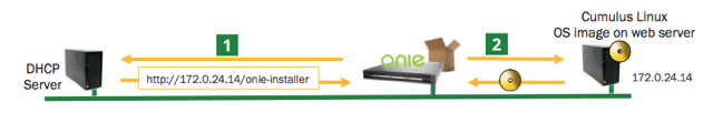
The easiest way to install Cumulus Linux with ONIE is with local HTTP discovery:
If your host (laptop or server) is IPv6-enabled, make sure it is
running a web server. If the host is IPv4-enabled, make sure it is
running DHCP in addition to a web server.
Download the Cumulus Linux
installation file to the root directory of the web server. Rename
this file onie-installer.
Connect your host using an Ethernet cable to the management Ethernet
port of the switch.
Power on the switch. The switch downloads the ONIE image installer
and boots. You can watch the progress of the install in your
terminal. After the installation completes, the Cumulus Linux login
prompt appears in the terminal window.
These steps describe a flexible unattended installation method. You do not need a console cable. A fresh install with ONIE using a local web server typically completes in less than ten minutes.
You have more options for installing Cumulus Linux with ONIE. Read
Installing a New Cumulus Linux Image
to install Cumulus Linux using ONIE in the following ways:
DHCP/web server with and without DHCP options
Web server without DHCP
FTP or TFTP without a web server
Local file
USB
ONIE supports many other discovery mechanisms using USB (copy the
installer to the root of the drive), DHCPv6 and DHCPv4, and image copy
methods including HTTP, FTP, and TFTP. For more information on these
discovery methods, refer to the ONIE documentation.
After installing Cumulus Linux, you are ready to:
Log in to Cumulus Linux on the switch.
Install the Cumulus Linux license.
Configure Cumulus Linux. This quick start guide provides instructions on configuring switch ports and a loopback interface.
Getting Started
When starting Cumulus Linux for the first time, the management port makes a DHCPv4 request. To determine the IP address of the switch, you can cross reference the MAC address of the switch with your DHCP server. The MAC address is typically located on the side of the switch or on the box in which the unit ships.
Login Credentials
The default installation includes one system account, root, with full system privileges, and one user account, cumulus, with sudo privileges. The root account password is set to null by default (which prohibits login). In Cumulus Linux 3.7.11 and earlier, the cumulus account is configured with this default password:
CumulusLinux!
For optimum security, change the default password (using the passwd command) before you configure Cumulus Linux on the switch.
In Cumulus Linux 3.7.12 and later, the cumulus account is configured with this default password:
cumulus
The first time you log into Cumulus Linux 3.7.12 or later, you are required to change this default password. When prompted, enter a new password, then confirm the new password.
In this quick start guide, you use the cumulus account to configure Cumulus Linux.
All accounts except root are permitted remote SSH login; you can use sudo to grant a non-root account root-level access. Commands that change the system configuration require this elevated level of access.
You are encouraged to perform management and configuration over the network, either in band or out of band. Using a serial console is fully supported; however, many customers prefer the convenience of network-based management.
Typically, switches ship from the manufacturer with a mating DB9 serial cable. Switches with ONIE are always set to a 115200 baud rate.
Wired Ethernet Management
Switches supported in Cumulus Linux always contain at least one dedicated Ethernet management port, which is named eth0. This interface is geared specifically for out-of-band management use. The management interface uses DHCPv4 for addressing by default. You can set a static IP address with the Network Command Line Utility (NCLU).
To set a static IP address, run the interface address and interface gateway NCLU commands. For example:
cumulus@switch:~$ net add interface eth0 ip address 192.0.2.42/24
cumulus@switch:~$ net add interface eth0 ip gateway 192.0.2.1
cumulus@switch:~$ net pending
cumulus@switch:~$ net commit
auto eth0
iface eth0
    address 192.0.2.42/24
    gateway 192.0.2.1
auto eth0
 iface eth0
    address 192.0.2.42/24
    gateway 192.0.2.1
Configure the Hostname and Timezone
To change the hostname, run net add hostname, which modifies both the /etc/hostname and /etc/hosts files with the desired hostname.
cumulus@switch:~$ net add hostname <hostname>
cumulus@switch:~$ net pending
cumulus@switch:~$ net commit
Do not use an underscore (_) in the hostname; underscores are not permitted.
Avoid using apostrophes or non-ASCII characters in the hostname. Cumulus Linux does not parse these characters.
The command prompt in the terminal does not reflect the new hostname until you either log out of the switch or start a new shell.
When you use the NCLU command to set the hostname, DHCP does not override the hostname when you reboot the switch. However, if you disable the hostname setting with NCLU, DHCP does override the hostname the next time you reboot the switch.
To update the timezone, use NTP interactive mode:
Run the following command in a terminal:
sudo dpkg-reconfigure tzdata
Follow the on screen menu options to select the geographic area and region.
Programs that are already running (including log files) and users currently logged in, do not see timezone changes made with interactive mode. To have the timezone set for all services and daemons, a reboot is required.
Verify the System Time
Before you install the license, verify that the date and time on the
switch are correct. You must correct the date and time if they
are incorrect. The wrong date and time can have impacts on the switch,
such as the inability to synchronize with Puppet or return errors like
this one after you restart switchd:
Warning: Unit file of switchd.service changed on disk, systemctl daemon-reload recommended.
Install the License
Cumulus Linux is licensed on a per-instance basis. Each network system is fully operational, enabling any capability to be utilized on the switch with the exception of forwarding on switch panel ports. Only eth0 and console ports are activated on an unlicensed instance of Cumulus Linux. Enabling front panel ports requires a license.
NVIDIA provides a generic license for Cumulus Linux. Download the license from the NVIDIA Enterprise support portal and apply it.
There are three ways to install the license onto the switch:
Copy the license from a local server. Create a text file with the license and copy it to a server accessible from the switch. On the switch, use the following command to transfer the file directly on the switch, then install the license file:
It is not necessary to reboot the switch to activate the switch ports.
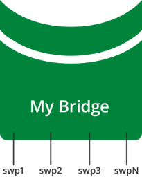
After you install the license, restart the switchd service. All front
panel ports become active and show up as swp1, swp2, and so on.
Restarting the switchd service causes all network ports to reset, interrupting network services, in addition to resetting the switch hardware configuration.
If a license is not installed on a Cumulus Linux switch, the switchd service does not start. After you install the license, start switchd as described above.
Configure Breakout Ports with Splitter Cables
If you are using 4x10G DAC or AOC cables, or want to break out 100G or
40G switch ports, configure the breakout ports. For more details, see
Breakout Ports.
Test Cable Connectivity
By default, all data plane ports (every Ethernet port except the management interface, eth0) are disabled.
To test cable connectivity, administratively enable a port:
cumulus@switch:~$ net add interface swp1
cumulus@switch:~$ net pending
cumulus@switch:~$ net commit
To administratively enable all physical ports, run the following command, where swp1-52 represents a switch with switch ports numbered from swp1 to swp52:
cumulus@switch:~$ net add interface swp1-52
cumulus@switch:~$ net pending
cumulus@switch:~$ net commit
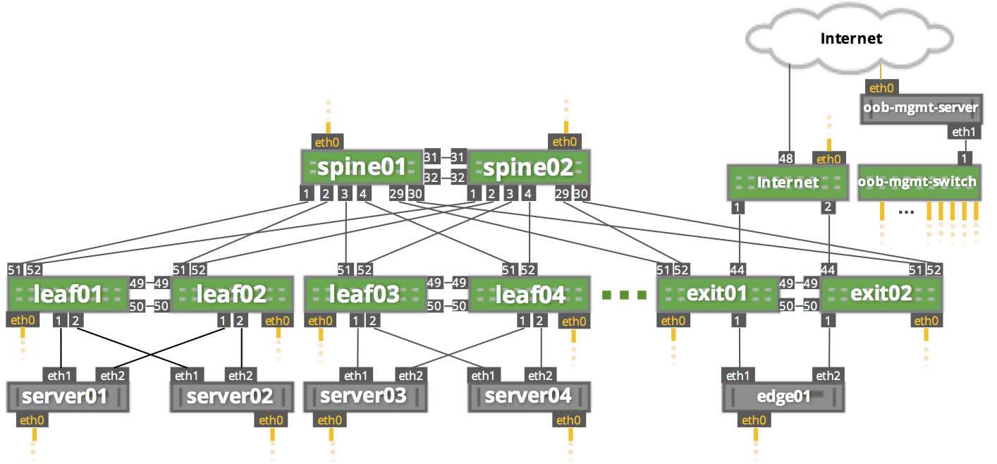
To view link status, use the net show interface all command. The following examples show the output of ports in admin down, down, and up modes:
cumulus@switch:~$ net show interface all
State Name Spd MTU Mode LLDP Summary
----- ------------- --- ----- ------------- ---------------------- -------------------------
UP lo N/A 65536 Loopback IP: 127.0.0.1/8
lo IP: 10.0.0.11/32
lo IP: 10.0.0.112/32
lo IP: ::1/128
UP eth0 1G 1500 Mgmt oob-mgmt-switch (swp6) Master: mgmt(UP)
eth0 IP: 192.168.0.11/24(DHCP)
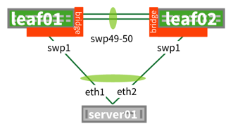
UP swp1 1G 9000 BondMember server01 (eth1) Master: bond01(UP)
UP swp2 1G 9000 BondMember server02 (eth1) Master: bond02(UP)
ADMDN swp45 N/A 1500 NotConfigured
ADMDN swp46 N/A 1500 NotConfigured
ADMDN swp47 N/A 1500 NotConfigured
ADMDN swp48 N/A 1500 NotConfigured
UP swp49 1G 9000 BondMember leaf02 (swp49) Master: peerlink(UP)
UP swp50 1G 9000 BondMember leaf02 (swp50) Master: peerlink(UP)
UP swp51 1G 9216 NotConfigured spine01 (swp1)
UP swp52 1G 9216 NotConfigured spine02 (swp1)
UP bond01 1G 9000 802.3ad Master: bridge(UP)
bond01 Bond Members: swp1(UP)
UP bond02 1G 9000 802.3ad Master: bridge(UP)
bond02 Bond Members: swp2(UP)
UP bridge N/A 1500 Bridge/L2
UP mgmt N/A 65536 Interface/L3 IP: 127.0.0.1/8
UP peerlink 2G 9000 802.3ad Master: bridge(UP)
peerlink Bond Members: swp49(UP)
peerlink Bond Members: swp50(UP)
DN peerlink.4094 2G 9000 SubInt/L3 IP: 169.254.1.1/30
ADMDN vagrant N/A 1500 NotConfigured
UP vlan13 N/A 1500 Interface/L3 Master: vrf1(UP)
vlan13 IP: 10.1.3.11/24
UP vlan13-v0 N/A 1500 Interface/L3 Master: vrf1(UP)
vlan13-v0 IP: 10.1.3.1/24
UP vlan24 N/A 1500 Interface/L3 Master: vrf1(UP)
vlan24 IP: 10.2.4.11/24
UP vlan24-v0 N/A 1500 Interface/L3 Master: vrf1(UP)
vlan24-v0 IP: 10.2.4.1/24
UP vlan4001 N/A 1500 NotConfigured Master: vrf1(UP)
UP vni13 N/A 9000 Access/L2 Master: bridge(UP)
UP vni24 N/A 9000 Access/L2 Master: bridge(UP)
UP vrf1 N/A 65536 NotConfigured
UP vxlan4001 N/A 1500 Access/L2 Master: bridge(UP)
Configure Switch Ports
Layer 2 Port Configuration
Cumulus Linux does not put all ports into a bridge by default. To create a bridge and configure one or more front panel ports as members of the bridge, use the following examples as a guide.
Examples
In the following configuration example, the front panel port swp1 is placed into a bridge called bridge. The NCLU commands are:
cumulus@switch:~$ net add bridge bridge ports swp1
cumulus@switch:~$ net pending
cumulus@switch:~$ net commit
The commands above create the following /etc/network/interfaces snippet:
auto bridge
iface bridge
    bridge-ports swp1
    bridge-vlan-aware yes
You can add a range of ports in one command. For example, add swp1 through swp10, swp12, and swp14 through swp20 to bridge:
cumulus@switch:~$ net add bridge bridge ports swp1-10,12,14-20
cumulus@switch:~$ net pending
cumulus@switch:~$ net commit
The commands above create the following snippet in the /etc/network/interfaces file:
To view the changes in the kernel, use the brctl command:
cumulus@switch:~$ brctl show
bridge name     bridge id              STP enabled     interfaces
bridge          8000.443839000004      yes             swp1
                                                       swp2
Layer 3 Port Configuration
You can also use NCLU to configure a front panel port or bridge interface as a layer 3 port.
In the following configuration example, the front panel port swp1 is configured as a layer 3 access port:
cumulus@switch:~$ net add interface swp1 ip address 10.1.1.1/30
cumulus@switch:~$ net pending
cumulus@switch:~$ net commit
The commands above create the following snippet in the /etc/network/interfaces file:
auto swp1
iface swp1
    address 10.1.1.1/30
To add an IP address to a bridge interface, you must put it into a VLAN interface. If you want to use a VLAN other than the native one, set the bridge PVID:
cumulus@switch:~$ net add vlan 100 ip address 10.2.2.1/24
cumulus@switch:~$ net add bridge bridge pvid 100
cumulus@switch:~$ net pending
cumulus@switch:~$ net commit
The commands above create the following snippet in the /etc/network/interfaces file:
auto bridge
iface bridge
    bridge-ports swp1
    bridge-pvid 100
    bridge-vlan-aware yes

auto vlan100
iface vlan100
    address 192.168.10.1/24
    vlan-id 100
    vlan-raw-device bridge
To view the changes in the kernel, use the ip addr show command:
cumulus@switch:~$ ip addr show
...
4. swp1: <BROADCAST,MULTICAST,UP,LOWER_UP> mtu 1500 qdisc pfifo_fast master bridge state UP group default qlen 1000
    link/ether 44:38:39:00:6e:fe brd ff:ff:ff:ff:ff:ff
...

14: bridge: <BROADCAST,MULTICAST,UP,LOWER_UP> mtu 1500 qdisc noqueue state UP group default
    link/ether 44:38:39:00:00:04 brd ff:ff:ff:ff:ff:ff
    inet6 fe80::4638:39ff:fe00:4/64 scope link
        valid_lft forever preferred_lft forever
...
Configure a Loopback Interface
Cumulus Linux has a loopback preconfigured in the /etc/network/interfaces file. When the switch boots up, it has a loopback interface called lo, which is up and assigned an IP address of 127.0.0.1.
The loopback interface lo must always be specified in the /etc/network/interfaces file and must always be up.
To see the status of the loopback interface (lo), use the net show interface lo command:
cumulus@switch:~$ net show interface lo
     Name    MAC                Speed      MTU  Mode
--  ------  -----------------  -------  -----  --------
UP  lo      00:00:00:00:00:00  N/A      65536  Loopback

Alias
-----
loopback interface
IP Details
-------------------------  --------------------
IP:                        127.0.0.1/8, ::1/128
IP Neighbor(ARP) Entries:  0
Note that the loopback is up and is assigned an IP address of 127.0.0.1.
To add an IP address to a loopback interface, configure the lo interface with NCLU:
cumulus@switch:~$ net add loopback lo ip address 10.1.1.1/32
cumulus@switch:~$ net pending
cumulus@switch:~$ net commit
You can configure multiple loopback addresses by adding additional address lines:
cumulus@switch:~$ net add loopback lo ip address 172.16.2.1/24
cumulus@switch:~$ net pending
cumulus@switch:~$ net commit
The commands above create the following snippet in the /etc/network/interfaces file:
auto lo
iface lo inet loopback
    address 10.1.1.1/32
    address 172.16.2.1/24
Installation Management
You can only install one image of the operating system on a Cumulus Linux switch. This section discusses how to install new and update existing Cumulus Linux disk images, and configure those images with additional applications (using packages).
System Configuration
This section provides information to help you set up your system for authentication, configure packet filtering, set the time and date, and provides other related system tasks.
Layer 1 and Switch Ports
This section describes the physical layer configuration and how to configure switch ports.
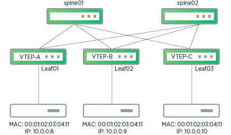
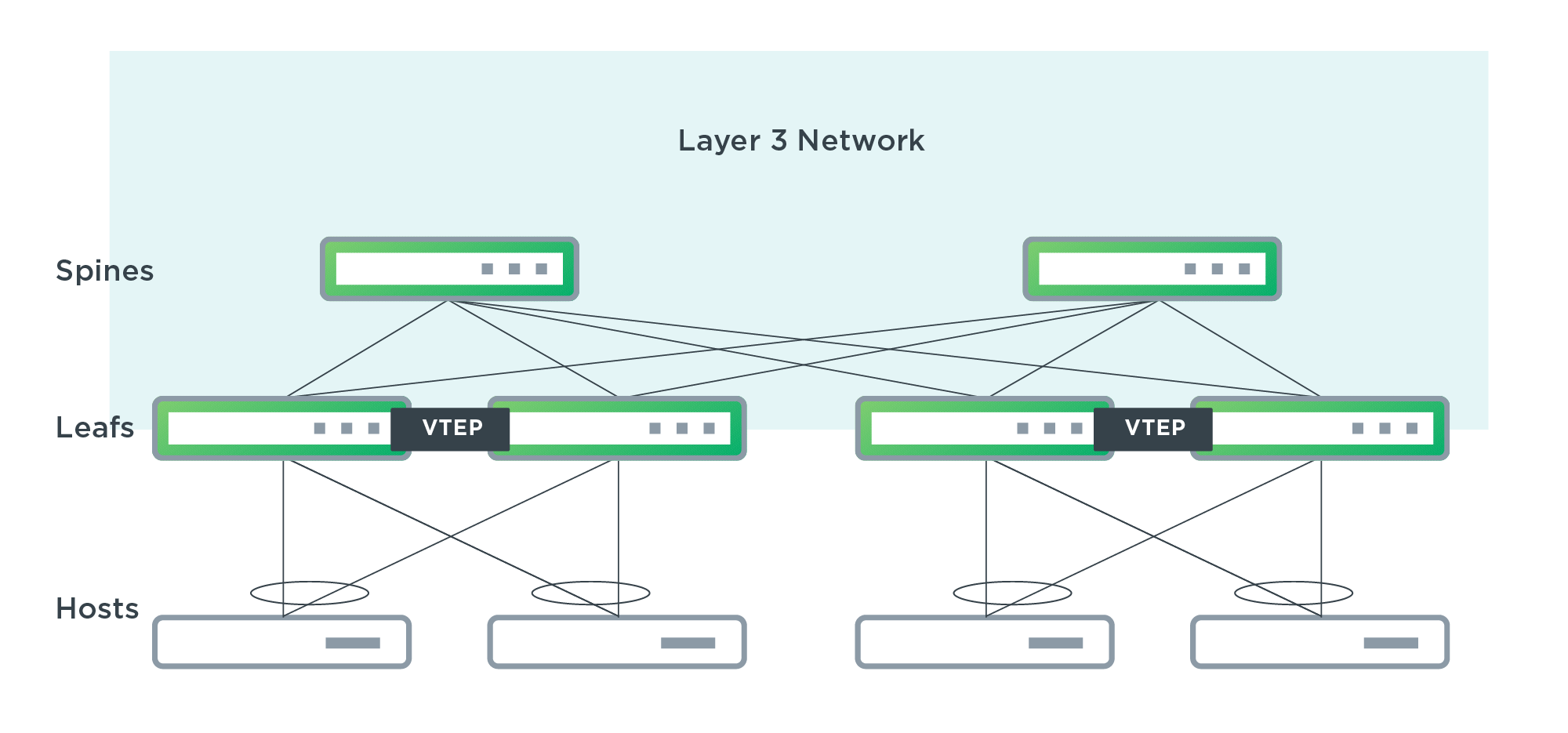
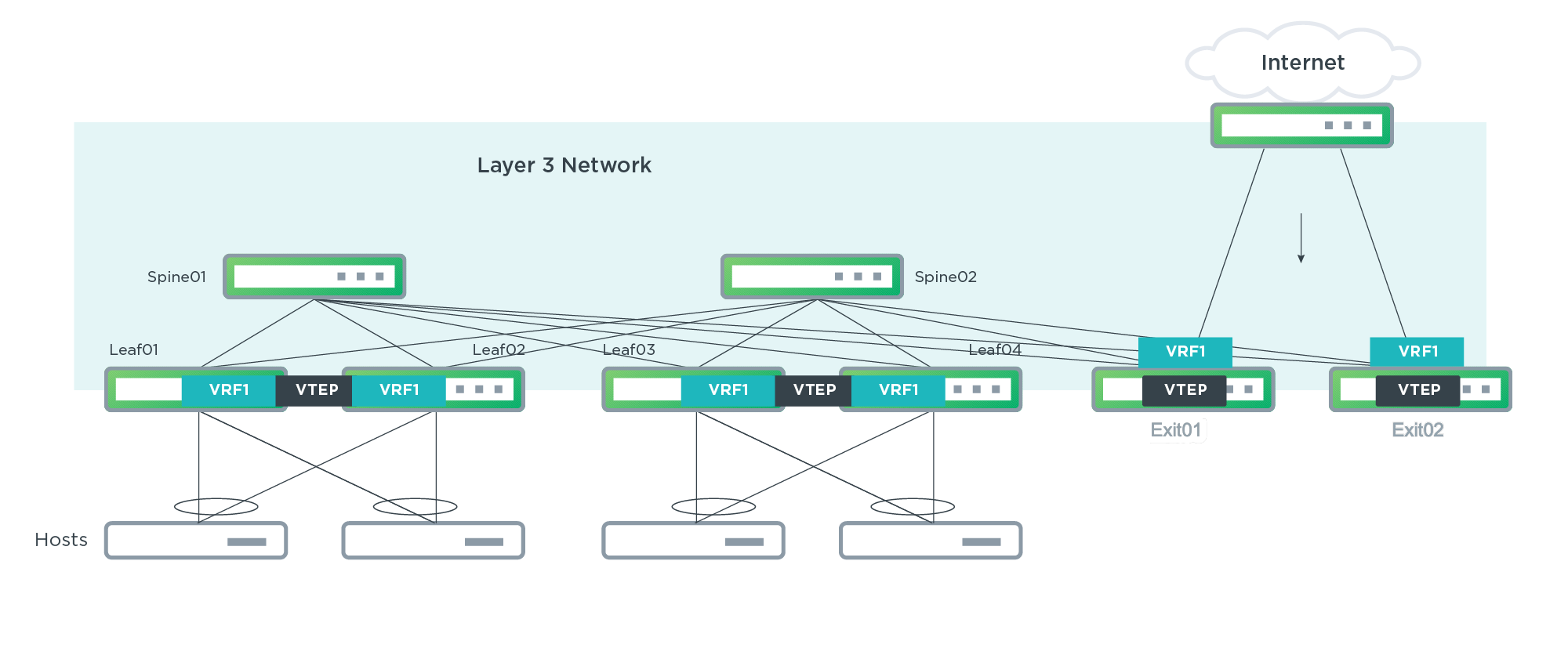
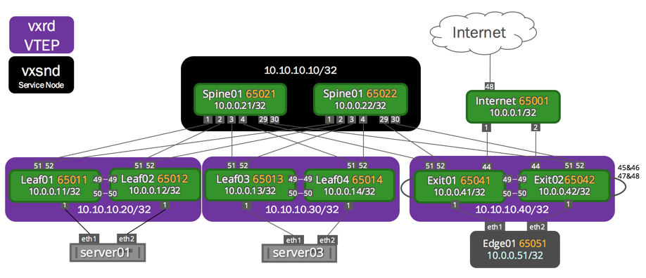
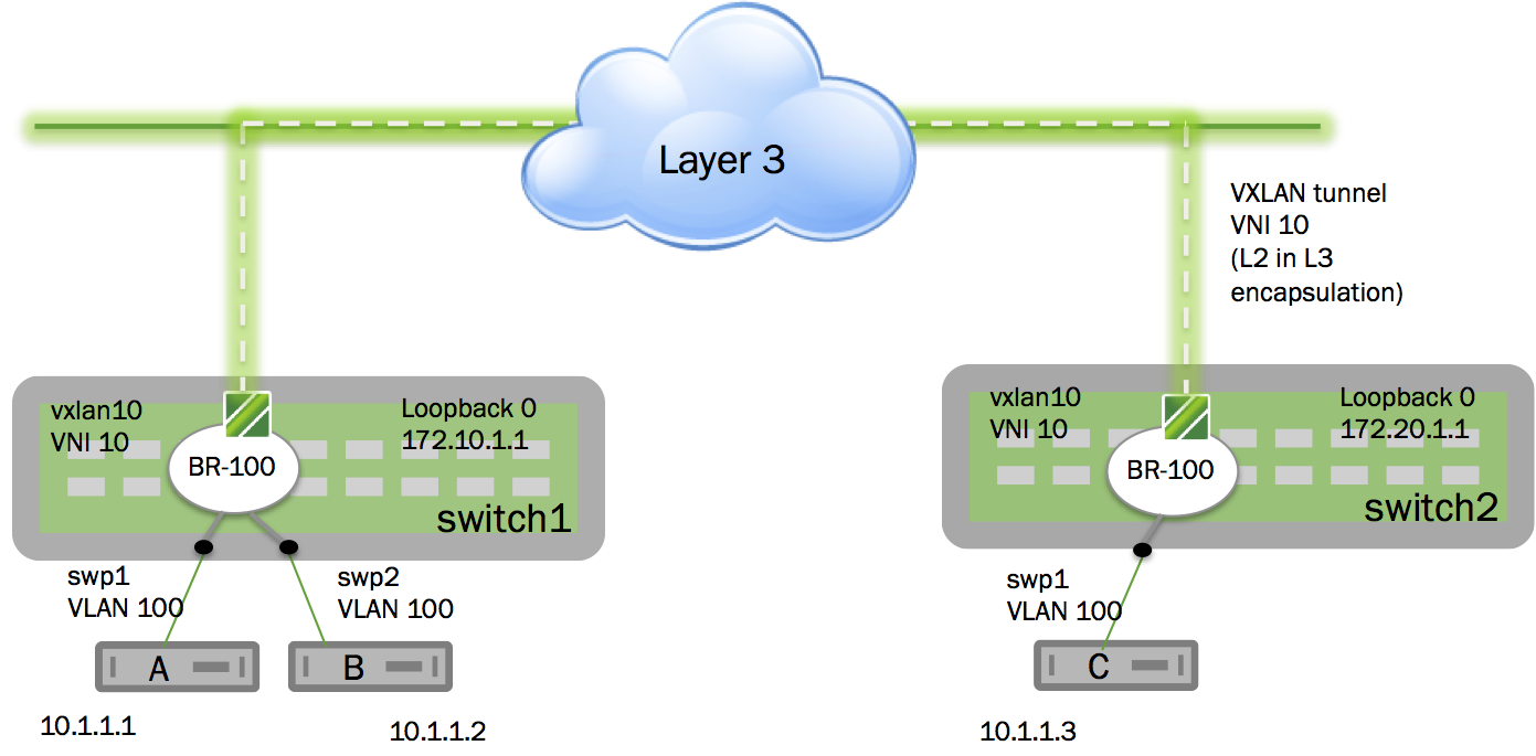
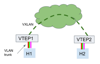
VXLAN (Virtual Extensible LAN) is a standard overlay protocol that abstracts logical virtual networks from the physical network underneath. You can deploy simple and scalable layer 3 Clos architectures while extending layer 2 segments over that layer 3 network.
VXLAN uses a VLAN-like encapsulation technique to encapsulate MAC-based layer 2 Ethernet frames within layer 3 UDP packets. Each virtual network is a VXLAN logical layer 2 segment. VXLAN scales to 16 million segments (a 24-bit VXLAN network identifier (VNI ID) in the VXLAN header) for multi-tenancy.
Hosts on a given virtual network are joined together through an overlay protocol that initiates and terminates tunnels at the edge of the multi-tenant network, typically the hypervisor vSwitch or top of rack. These edge points are the VXLAN tunnel end points (VTEP).
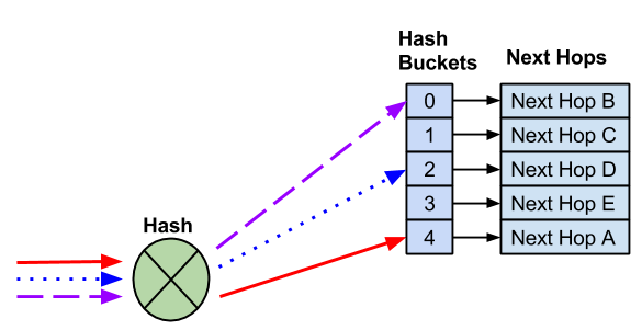
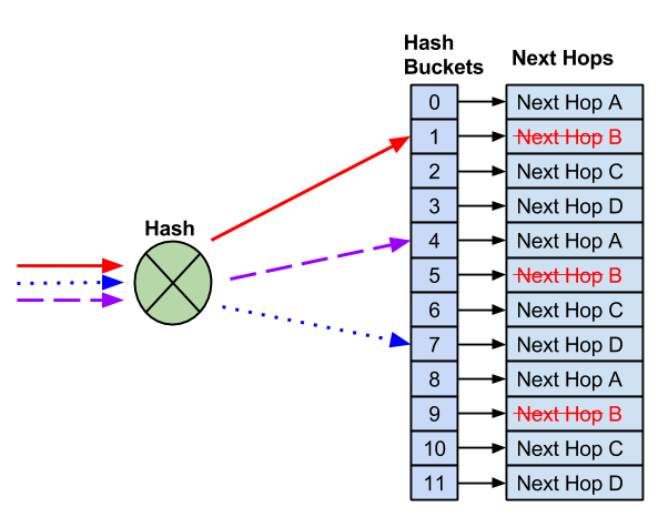
Cumulus Linux can initiate and terminate VTEPs in hardware and supports wire-rate VXLAN. VXLAN provides an efficient hashing scheme across the IP fabric during the encapsulation process; the source UDP port is unique, with the hash based on layer 2 through layer 4 information from the original frame. The UDP destination port is the standard port 4789.
VXLAN is supported only on switches using the Broadcom Tomahawk, Trident II, Trident II+ and Trident3 chipsets, as well as the Mellanox Spectrum chipset.
VXLAN encapsulation over layer 3 subinterfaces (for example, swp3.111) or SVIs is not supported as traffic transiting through the switch may get dropped; even if the subinterface is used only for underlay traffic and does not perform VXLAN encapsulation, traffic might still get dropped. Only configure VXLAN uplinks as layer 3 interfaces without any subinterfaces (for example, swp3).
The VXLAN tunnel endpoints cannot share a common subnet; there must be at least one layer 3 hop between the VXLAN source and destination.
Caveats and Errata
Cut-through Mode and Store and Forward Switching
On switches using Broadcom Tomahawk, Trident II, Trident II+, and Trident3 ASICs, Cumulus Linux supports store and forward switching for VXLANs but does not support cut-through mode.
On switches using Mellanox Spectrum ASICs, Cumulus Linux supports cut-through mode for VXLANs but does not support store and forward switching.
MTU Size for Virtual Network Interfaces
Ensure that the maximum transmission unit (MTU) size for a virtual network interface is 50 bytes smaller than the MTU for the physical interfaces on the switch. For more information on setting the MTU, read Switch Port Attributes.
Layer 3 and Layer 2 VNIs Cannot Share the Same ID
A layer 3 VNI and a layer 2 VNI cannot have the same ID. If the VNI IDs are the same, the layer 2 VNI does not get created.
TC Filters
NVIDIA recommends you run TC filter commands on each VLAN interface on the VTEP to install rules to protect the UDP port that Cumulus Linux uses for VXLAN encapsulation against VXLAN hopping vulnerabilities. If you have VRR configured on the VLAN, add a similar rule for the VRR device.
The following example installs an IPv4 and an IPv6 filter on vlan10 to protect the default port 4879:
cumulus@switch:mgmt:~$ tc filter add dev vlan10 prio 1 protocol ip ingress flower ip_proto udp dst_port 4879 action drop
cumulus@switch:mgmt:~$ tc filter add dev vlan10 prio 2 protocol ipv6 ingress flower ip_proto udp dst_port 4879 action drop
The following example installs an IPv4 and an IPv6 filter on VRR device vlan10-v0 to protect port 4879:
cumulus@switch:mgmt:~$ tc filter add dev vlan10-v0 prio 1 protocol ip ingress flower ip_proto udp dst_port 4879 action drop
cumulus@switch:mgmt:~$ tc filter add dev vlan10-v0 prio 2 protocol ipv6 ingress flower ip_proto udp dst_port 4879 action drop
This section describes layer 3 configuration. Read this section to understand routing protocols and learn how to configure routing on the Cumulus Linux switch.
Monitoring and Troubleshooting
This chapter introduces monitoring and troubleshooting Cumulus Linux.
Serial Console
The serial console can be a useful tool for debugging issues, especially
when you find yourself rebooting the switch often or if you do not have a
reliable network connection.
The default serial console baud rate is 115200, which is the baud rate
ONIE uses.
Configure the Serial Console on ARM Switches
On ARM switches, the U-Boot environment variable baudrate identifies
the baud rate of the serial console. To change the baudrate variable,
use the fw_setenv command:
cumulus@switch:~$ sudo fw_setenv baudrate 9600
Updating environment variable: `baudrate'
Proceed with update [N/y]? y
You must reboot the switch for the baudrate change to take effect.
The valid values for baudrate are:
300
600
1200
2400
4800
9600
19200
38400
115200
Configure the Serial Console on x86 Switches
On x86 switches, you configure serial console baud rate by editing grub.
Incorrect configuration settings in grub can cause the switch to be
inaccessible via the console. Grub changes should be carefully reviewed
before implementation.
The valid values for the baud rate are:
300
600
1200
2400
4800
9600
19200
38400
115200
To change the serial console baud rate:
Edit /etc/default/grub. The two relevant lines in
/etc/default/grub are as follows; replace the 115200 value with
a valid value specified above in the --speed variable in the first
line and in the console variable in the second line:
After you save your changes to the grub configuration, type the
following at the command prompt:
cumulus@switch:~$ update-grub
If you plan on accessing the switch BIOS over the serial console, you need to update the baud rate in the switch BIOS. For more information, see this this knowledge base article.
Reboot the switch.
Change the Console Log level
By default, the console prints all log messages except debug messages. To tune console logging to be less verbose so that certain levels of messages are not printed, run the dmesg -n <level> command, where the log levels are:
Level
Description
0
Emergency messages (the system is about to crash or is unstable).
1
Serious conditions; you must take action immediately.
2
Critical conditions (serious hardware or software failures).
3
Error conditions (often used by drivers to indicate difficulties with the hardware).
4
Warning messages (nothing serious but might indicate problems).
5
Message notifications for many conditions, including security events.
6
Informational messages.
7
Debug messages.
Only messages with a value lower than the level specified are printed to the console. For example, if you specify level 3, only level 2 (critical conditions), level 1 (serious conditions), and level 0 (emergency messages) are printed to the console:
cumulus@switch:~$ sudo dmesg -n 3
Alternatively, you can run dmesg --console-level <level> command, where the log levels are emerg, alert, crit, err, warn, notice, info, or debug. For example, to print critical conditions, run the following command:
cumulus@switch:~$ sudo dmesg --console-level crit
The dmesg command is applied until the next reboot.
For more details about the dmesg command, run man dmesg.
Show General System Information
Two commands are helpful for getting general information about the
switch and the version of Cumulus Linux you are running. These are
helpful with system diagnostics and if you need to submit a support
request.
For information about the version of Cumulus Linux running on the
switch, run net show version, which displays the contents of
/etc/lsb-release:
cumulus@switch:~$ net show version
NCLU_VERSION=1.0
DISTRIB_ID="Cumulus Linux"
DISTRIB_RELEASE=3.4.0
DISTRIB_DESCRIPTION="Cumulus Linux 3.4.0"
For general information about the switch, run net show system, which
gathers information about the switch from a number of files in the
system:
cumulus@switch:~$ net show system
Hostname......... celRED

Build............ Cumulus Linux 3.7.4~1551312781.35d3264
Uptime........... 8 days, 12:24:01.770000

Model............ Cel REDSTONE
CPU.............. x86_64 Intel Atom C2538 2.4 GHz
Memory........... 4GB
Disk............. 14.9GB
ASIC............. Broadcom Trident2 BCM56854
Ports............ 48 x 10G-SFP+ & 6 x 40G-QSFP+
Base MAC Address. a0:00:00:00:00:50
Serial Number.... A1010B2A011212AB000001
Diagnostics Using cl-support
You can use cl-support to generate a single export file that contains
various details and the configuration from a switch. This is useful for
remote debugging and troubleshooting. For more information about
cl-support, read Understanding the cl-support Output File.
You should run cl-support before you submit a support request as this file helps in the investigation of issues.
cumulus@switch:~$ sudo cl-support -h
Usage: cl-support [-h] [-s] [-t] [-v] [reason]...

Args:
[reason]: Optional reason to give for invoking cl-support.
             Saved into tarball's cmdline.args file.
Options:
-h: Print this usage statement
-s: Security sensitive collection
-t: User filename tag
-v: Verbose
-e MODULES: Enable modules. Comma separated module list (run with -e help for module names)
-d MODULES: Disable modules. Comma separated module list (run with -d help for module names)
Send Log Files to a syslog Server
The remote syslog server can be configured on the switch using the
following configuration:
cumulus@switch:~$ net add syslog host ipv4 192.168.0.254 port udp 514
cumulus@switch:~$ net pending
cumulus@switch:~$ net commit
This creates a file called /etc/rsyslog.d/11-remotesyslog.conf in the
rsyslog directory. The file has the following content:
cumulus@switch:~$ cat /etc/rsyslog.d/11-remotesyslog.conf
# This file was automatically generated by NCLU.
*.*   @192.168.0.254:514   # UDP
Logging on Cumulus Linux is done with rsyslog.
rsyslog provides both local logging to the syslog file as well as the ability
to export logs to an external syslog server. High precision timestamps are enabled
for all rsyslog log files; here’s an example:
2015-08-14T18:21:43.337804+00:00 cumulus switchd[3629]: switchd.c:1409 switchd version 1.0-cl2.5+5
There are applications in Cumulus Linux that could write directly to a
log file without going through rsyslog. These files are typically
located in /var/log/.
All Cumulus Linux rules are stored in separate files in
/etc/rsyslog.d/, which are called at the end of the GLOBAL DIRECTIVES section of /etc/rsyslog.conf. As a result, the RULES
section at the end of rsyslog.conf is ignored because the messages
have to be processed by the rules in /etc/rsyslog.d and then dropped
by the last line in /etc/rsyslog.d/99-syslog.conf.
Local Logging
Most logs within Cumulus Linux are sent through rsyslog, which then
writes them to files in the /var/log directory. There are default
rules in the /etc/rsyslog.d/ directory that define where the logs are
written:
Rule
Purpose
10-rules.conf
Sets defaults for log messages, include log format and log rate limits.
15-crit.conf
Logs crit, alert or emerg log messages to /var/log/crit.log to ensure they are not rotated away rapidly.
20-clagd.conf
Logs clagd messages to /var/log/clagd.log for MLAG.
22-linkstate.conf
Logs link state changes for all physical and logical network links to /var/log/linkstate
Logs routing protocol messages to /var/log/frr/frr.log. This includes BGP and OSPF log messages.
99-syslog.conf
All remaining processes that use rsyslog are sent to /var/log/syslog.
Log files that are rotated are compressed into an archive. Processes
that do not use rsyslog write to their own log files within the
/var/log directory. For more information on specific log files, see
Troubleshooting Log Files.
Enable Remote syslog
By default not all log messages are sent to a remote server
If you need to send other log files - such as switchd logs - to a
syslog server, do the following:
Create a file in /etc/rsyslog.d/. Make sure it starts with a
number lower than 99 so that it executes before log messages are
dropped in, such as 20-clagd.conf or 25-switchd.conf. Our
example file is called /etc/rsyslog.d/11-remotesyslog.conf. Add
content similar to the following:
## Logging switchd messages to remote syslog server

@192.168.1.2:514
This configuration sends log messages to a remote syslog server
for the following processes: clagd, switchd, ptmd, rdnbrd,
netd and syslog. It follows the same syntax as the
/var/log/syslog file, where @ indicates UDP, 192.168.1.2 is
the IP address of the syslog server, and 514 is the UDP port.
For TCP-based syslog, use two @@ before the IP address @@192.168.1.2:514.
The numbering of the files in /etc/rsyslog.d/ dictates how the rules are installed into rsyslog.d. Lower numbered rules are processed first, and rsyslog processing terminates with the stop keyword. For example, the rsyslog configuration for FRR is stored in the 45-frr.conf file with an explicit stop at the bottom of the file. FRR messages are logged to the /var/log/frr/frr.log file on the local disk only (these messages are not sent to a remote server using the default configuration). To log FRR messages remotely in addition to writing FRR messages to the local disk, rename the 99-syslog.conf file to 11-remotesyslog.conf. FRR messages are first processed by the 11-remotesyslog.conf rule (transmit to remote server), then continue to be processed by the 45-frr.conf file (write to local disk in the /var/log/frr/frr.log file).
Do not use the imfile module with any file written by rsyslogd.
You can write to syslog with
management VRF enabled by applying the
following configuration; this configuration is commented out in the
/etc/rsyslog.d/11-remotesyslog.conf file:
cumulus@switch:~$ cat /etc/rsyslog.d/11-remotesyslog.conf
## Copy all messages to the remote syslog server at 192.168.0.254 port 514
action(type="omfwd" Target="192.168.0.254" Device="mgmt" Port="514" Protocol="udp")
For each syslog server, configure a unique action line. For example,
to configure two syslog servers at 192.168.0.254 and 10.0.0.1:
cumulus@switch:~$ cat /etc/rsyslog.d/11-remotesyslog.conf
## Copy all messages to the remote syslog servers at 192.168.0.254 and 10.0.0.1 port 514
action(type="omfwd" Target="192.168.0.254" Device="mgmt" Port="514" Protocol="udp")
action(type="omfwd" Target="10.0.0.1" Device="mgmt" Port="514" Protocol="udp")
If you configure remote logging to use the TCP protocol, local logging might stop when the remote syslog server is unreachable. To avoid this behavior, configure a disk queue size and maximum retry count in your rsyslog configuration:
If you want to limit the number of syslog messages that can be written
to the syslog file from individual processes, add the following
configuration to /etc/rsyslog.conf. Adjust the interval and burst
values to rate-limit messages to the appropriate levels required by your
environment. For more information, read the
rsyslog documentation.
Harmless syslog Error: Failed to reset devices.list
The following message gets logged to /var/log/syslog when you run
systemctl daemon-reload and during system boot:
systemd[1]: Failed to reset devices.list on /system.slice: Invalid argument
This message is harmless, and can be ignored. It is logged when
systemd attempts to change cgroup attributes that are read only. The
upstream version of systemd has been modified to not log this message by
default.
The systemctl daemon-reload command is often issued when Debian
packages are installed, so the message may be seen multiple times when
upgrading packages.
Syslog Troubleshooting Tips
You can use the following commands to troubleshoot syslog issues.
Verifying that rsyslog is Running
To verify that the rsyslog service is running, use the sudo systemctl status rsyslog.service command:
cumulus@leaf01:mgmt-vrf:~$ sudo systemctl status rsyslog.service
rsyslog.service - System Logging Service
  Loaded: loaded (/lib/systemd/system/rsyslog.service; enabled)
  Active: active (running) since Sat 2017-12-09 00:48:58 UTC; 7min ago
    Docs: man:rsyslogd(8)
          http://www.rsyslog.com/doc/
Main PID: 11751 (rsyslogd)
  CGroup: /system.slice/rsyslog.service
         └─11751 /usr/sbin/rsyslogd -n

Dec 09 00:48:58 leaf01 systemd[1]: Started System Logging Service.
Verify your rsyslog Configuration
After making manual changes to any files in the /etc/rsyslog.d
directory, use the sudo rsyslogd -N1 command to identify any errors in
the configuration files that might prevent the rsyslog service from
starting.
In the following example, a closing parenthesis is missing in the
11-remotesyslog.conf file, which is used to configure syslog for
management VRF:
cumulus@leaf01:mgmt-vrf:~$ cat /etc/rsyslog.d/11-remotesyslog.conf
action(type="omfwd" Target="192.168.0.254" Device="mgmt" Port="514" Protocol="udp"

cumulus@leaf01:mgmt-vrf:~$ sudo rsyslogd -N1
rsyslogd: version 8.4.2, config validation run (level 1), master config /etc/rsyslog.conf
rsyslogd: error during parsing file /etc/rsyslog.d/15-crit.conf, on or before line 3: invalid character '$' in object definition - is there an invalid escape sequence somewhere? [try http://www.rsyslog.com/e/2207 ]
rsyslogd: error during parsing file /etc/rsyslog.d/15-crit.conf, on or before line 3: syntax error on token 'crit_log' [try http://www.rsyslog.com/e/2207 ]
After correcting the invalid syntax, issuing the sudo rsyslogd -N1
command produces the following output.
cumulus@leaf01:mgmt-vrf:~$ cat /etc/rsyslog.d/11-remotesyslog.conf
action(type="omfwd" Target="192.168.0.254" Device="mgmt" Port="514" Protocol="udp")
cumulus@leaf01:mgmt-vrf:~$ sudo rsyslogd -N1
rsyslogd: version 8.4.2, config validation run (level 1), master config /etc/rsyslog.conf
rsyslogd: End of config validation run. Bye.
tcpdump
If a syslog server is not accessible to validate that syslog messages
are being exported, you can use tcpdump.
In the following example, a syslog server has been configured at
192.168.0.254 for UDP syslogs on port 514:
cumulus@leaf01:mgmt-vrf:~$ sudo tcpdump -i eth0 host 192.168.0.254 and udp port 514
A simple way to generate syslog messages is to use sudo in another
session, such as sudo date. Using sudo generates an authpriv log.
cumulus@leaf01:mgmt-vrf:~$ sudo tcpdump -i eth0 host 192.168.0.254 and udp port 514
tcpdump: verbose output suppressed, use -v or -vv for full protocol decode
listening on eth0, link-type EN10MB (Ethernet), capture size 262144 bytes
00:57:15.356836 IP leaf01.lab.local.33875 > 192.168.0.254.syslog: SYSLOG authpriv.notice, length: 105
00:57:15.364346 IP leaf01.lab.local.33875 > 192.168.0.254.syslog: SYSLOG authpriv.info, length: 103
00:57:15.369476 IP leaf01.lab.local.33875 > 192.168.0.254.syslog: SYSLOG authpriv.info, length: 85
To see the contents of the syslog file, use the tcpdump -X option:
This section discusses the various architectures and strategies available with Cumulus Linux and describes different solutions, such as RDMA over Converged Ethernet (RoCE).
Managing Cumulus Linux Disk Images
The Cumulus Linux operating system resides on a switch as a disk image. This section discusses how to manage the disk image.
To determine if your switch is on an x86 or ARM platform, run the uname -m command.
For example, on an x86 platform, uname -m outputs x86_64:
cumulus@x86switch$ uname -m
 x86_64
On an ARM platform, uname -m outputs armv7l:
cumulus@ARMswitch$ uname -m
 armv7l
Reprovision the System (Restart the Installer)
Reprovisioning the system deletes all system data from the switch.
To stage an ONIE installer from the network (where ONIE automatically locates the installer), run the onie-select -i command. A reboot is required for the reinstall to begin.
cumulus@switch:~$ sudo onie-select -i
WARNING:
WARNING: Operating System install requested.
WARNING: This will wipe out all system data.
WARNING:
Are you sure (y/N)? y
Enabling install at next reboot...done.
Reboot required to take effect.
To cancel a pending reinstall operation, run the onie-select -c command:
cumulus@switch:~$ sudo onie-select -c
Cancelling pending install at next reboot...done.
To stage an installer located in a specific location, run the onie-install -i command. You can specify a local, absolute or relative path, an HTTP or HTTPS server, SCP or FTP server. You can also stage a Zero Touch Provisioning (ZTP) script along with the installer. The onie-install command is typically used with the -a option to activate installation. If you do not specify the -a option, a reboot is required for the reinstall to begin.
The following example stages the installer located at http://203.0.113.10/image-installer together with the ZTP script located at http://203.0.113.10/ztp-script and activates installation and ZTP:
You can also specify these options together in the same command. For example:
cumulus@switch:~$ sudo onie-install -i http://203.0.113.10/image-installer -z http://203.0.113.10/ztp-script -a
To see more onie-install options, run man onie-install.
Migrate from Cumulus Linux to ONIE (Uninstall All Images and Remove the Configuration)
To remove all installed images and configurations and return the switch to its factory defaults, run the onie-select -k command.
The onie-select -k command takes a long time to run as it overwrites the entire NOS section of the flash. Only use this command if you want to erase all NOS data and take the switch out of service.
ONIE does not support front panel ports. After you run sudo onie-select -k to return the switch to its factory defaults, you must use the eth0 interface to provision the switch.
cumulus@switch:~$ sudo onie-select -k
WARNING:
WARNING: Operating System uninstall requested.
WARNING: This will wipe out all system data.
WARNING:
Are you sure (y/N)? y
Enabling uninstall at next reboot...done.
Reboot required to take effect.
A reboot is required for the uninstall to begin.
To cancel a pending uninstall operation, run the onie-select -c command:
cumulus@switch:~$ sudo onie-select -c
Cancelling pending uninstall at next reboot...done.
Boot into Rescue Mode
If your system becomes broken is some way, you can correct certain issues by booting into ONIE rescue mode. In rescue mode, the file systems are unmounted and you can use various Cumulus Linux utilities to try and resolve a problem.
To reboot the system into ONIE rescue mode, run the onie-select -r command:
cumulus@switch:~$ sudo onie-select -r
WARNING:
WARNING: Rescue boot requested.
WARNING:
Are you sure (y/N)? y
Enabling rescue at next reboot...done.
Reboot required to take effect.
A reboot is required to boot into rescue mode.
To cancel a pending rescue boot operation, run the onie-select -c command:
cumulus@switch:~$ sudo onie-select -c
Cancelling pending rescue at next reboot...done.
Inspect the Image File
The Cumulus Linux installation disk image file is executable. From a running switch, you can display, extract, and verify the contents of the image file.
To display the contents of the Cumulus Linux image file, pass the info option to the image file. For example, to display the contents of an image file called onie-installer located in the /var/lib/cumulus/installer directory:
To extract the contents of the image file, use with the extract <path> option. For example, to extract an image file called onie-installer located in the /var/lib/cumulus/installer directory to the mypath directory:
cumulus@switch:~$ sudo /var/lib/cumulus/installer/onie-installer extract mypath
total 181860
-rw-r--r-- 1 4000 4000 308 May 16 19:04 control
drwxr-xr-x 5 4000 4000 4096 Apr 26 21:28 embedded-installer
-rw-r--r-- 1 4000 4000 13273936 May 16 19:04 initrd
-rw-r--r-- 1 4000 4000 4239088 May 16 19:04 kernel
-rw-r--r-- 1 4000 4000 168701528 May 16 19:04 sysroot.tar
To verify the contents of the image file, use with the verify option. For example, to verify the contents of an image file called onie-installer located in the /var/lib/cumulus/installer directory:
cumulus@switch:~$ sudo /var/lib/cumulus/installer/onie-installer verify
Verifying image checksum ...OK.
Preparing image archive ... OK.
./cumulus-linux-bcm-amd64.bin.1: 161: ./cumulus-linux-bcm-amd64.bin.1: onie-sysinfo: not found
Verifying image compatibility ...OK.
Verifying system ram ...OK.
This topic discusses how to install a new Cumulus Linux disk image using ONIE, an open source project (equivalent to PXE on servers) that enables the installation of network operating systems (NOS) on bare metal switches.
Before you install Cumulus Linux, the switch can be in two different states:
No image is installed on the switch (the switch is only running ONIE).
Cumulus Linux is already installed on the switch but you want to use ONIE to reinstall Cumulus Linux or upgrade to a newer version.
The sections below describe some of the different ways you can install the Cumulus Linux disk image, such as using a DHCP/web server, FTP, TFTP, a local file, or a USB drive. Steps are provided for both installing directly from ONIE (if no image is installed on the switch) and from Cumulus Linux (if the image is already installed on the switch), where applicable. For additional methods to find and install the Cumulus Linux image, see the ONIE Design Specification.
Installing the Cumulus Linux disk image is destructive; configuration files on the switch are not saved; copy them to a different server before installing.
In the example commands, [PLATFORM] can be any supported Cumulus Linux platform, such as x86_64, or arm.
Run the sudo onie-install -h command to show the ONIE installer options.
After you install the Cumulus Linux disk image, you need to install the license file. Refer to Install the License.
In Cumulus Linux 3.7.12, the default password for the cumulus user account has changed to cumulus. The first time you log into Cumulus Linux, you are required to change this default password. Be sure to update any automation scripts before you upgrade to Cumulus Linux 3.7.12.
Install Using a DHCP/Web Server with DHCP Options
To install Cumulus Linux using a DHCP/web server with DHCP options, set up a DHCP/web server on your laptop and connect the eth0 management port of the switch to your laptop. After you connect the cable, the installation proceeds as follows:
The bare metal switch boots up and requests an IP address (DHCP request).
The DHCP server acknowledges and responds with DHCP option 114 and the location of the installation image.
ONIE downloads the Cumulus Linux disk image, installs, and reboots.
Success! You are now running Cumulus Linux.
The most common method is to send DHCP option 114 with the entire URL to the web server (this can be the same system). However, there are many other ways to use DHCP even if you do not have full control over DHCP. See the ONIE user guide for help with partial installer URLs and advanced DHCP options; both articles list more supported DHCP options.
Here is an example DHCP configuration with an ISC DHCP server:
Install Using a DHCP/Web Server without DHCP Options
Follow the steps below if you have a laptop on the same network and the switch can pull DHCP from the corporate network, but you cannot modify DHCP options (maybe it is controlled by another team).
Install from ONIE
Place the Cumulus Linux disk image in a directory on the web server.
From the Cumulus Linux command prompt, run the onie-install command, then reboot the switch.
cumulus@switch:~$ sudo onie-install -a -i /path/to/local/file/cumulus-install-[PLATFORM].bin
Install Using a USB Drive
Follow the steps below to install the Cumulus Linux disk image using a USB drive. Instructions are provided for x86 and ARM platforms.
Installing Cumulus Linux using a USB drive is fine for a single switch here and there but is not scalable. DHCP can scale to hundreds of switch installs with zero manual input unlike USB installs.
From a computer, prepare your USB drive by formatting it using one of the supported formats: FAT32, vFAT or EXT2.
Optional: Prepare a USB Drive inside Cumulus Linux
Use caution when performing the actions below; it is possible to severely damage your system with the following utilities.
Insert your USB drive into the USB port on the switch running Cumulus Linux and log in to the switch.
Examine output from cat /proc/partitions and sudo fdisk -l [device] to determine on which device your USB drive can be found. For example, sudo fdisk -l /dev/sdb.
These instructions assume your USB drive is the /dev/sdb device, which is typical if you insert the USB drive after the machine is already booted. However, if you insert the USB drive during the boot process, it is possible that your USB drive is the /dev/sda device. Make sure to modify the commands below to use the proper device for your USB drive.
Create a new partition table on the USB drive:
sudo parted /dev/sdb mklabel msdos
The parted utility should already be installed. However, if it is not, install it with: sudo -E apt-get install parted
Create a new partition on the USB drive:
sudo parted /dev/sdb -a optimal mkpart primary 0% 100%
Format the partition to your filesystem of choice using one of the examples below:
When using a Mac or Windows computer to rename the installation file, the file extension might still be present. Make sure to remove the file extension otherwise ONIE is not able to detect the file.
Insert the USB drive into the switch, then continue with the appropriate instructions below for your x86 or ARM platform.
Instructions for x86 Platforms
Click to expand x86 instructions...
Prepare the switch for installation:
If the switch is offline, connect to the console and power on the switch.
If the switch is already online in ONIE, use the reboot command.
SSH sessions to the switch get dropped after this step. To complete the remaining instructions, connect to the console of the switch. Cumulus Linux switches display their boot process to the console; you need to monitor the console specifically to complete the next step.
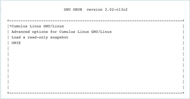
Monitor the console and select the ONIE option from the first GRUB screen shown below.
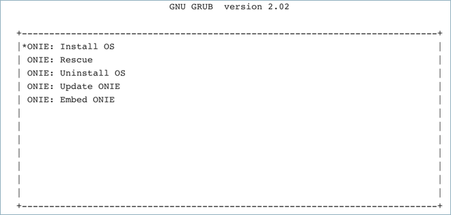
Cumulus Linux on x86 uses GRUB chainloading to present a second GRUB menu specific to the ONIE partition. No action is necessary in this menu to select the default option ONIE: Install OS.
The USB drive is recognized and mounted automatically. The image file is located and automatic installation of Cumulus Linux begins. Here is some sample output:
ONIE: OS Install Mode  ...

Version : quanta_common_rangeley-2014.05.05-6919d98-201410171013
Build  Date: 2014-10-17T10:13+0800
Info: Mounting kernel filesystems...  done.
Info: Mounting LABEL=ONIE-BOOT on /mnt/onie-boot  ...
initializing eth0...
scsi 6:0:0:0: Direct-Access  SanDisk Cruzer Facet 1.26 PQ: 0 ANSI: 6
sd 6:0:0:0: [sdb] 31266816 512-byte logical blocks: (16.0 GB/14.9 GiB)
sd 6:0:0:0: [sdb] Write Protect is off
sd 6:0:0:0: [sdb] Write cache: disabled, read cache: enabled, doesn't support DPO or FUA
sd 6:0:0:0: [sdb] Attached SCSI disk

<...snip...>

ONIE:  Executing installer: file://dev/sdb1/onie-installer-x86_64
Verifying image checksum ... OK.
Preparing image archive ... OK.
Dumping image info...
Control File Contents
=====================
Description: Cumulus  Linux
OS-Release:  3.0.0-3b46bef-201509041633-build
Architecture: amd64
Date:  Fri, 27 May 2016 17:10:30 -0700
Installer-Version:  1.2
Platforms: accton_as5712_54x accton_as6712_32x  mlx_sx1400_i73612 dell_s6000_s1220 dell_s4000_c2338 dell_s3000_c2338  cel_redstone_xp cel_smallstone_xp cel_pebble quanta_panther  quanta_ly8_rangeley quanta_ly6_rangeley quanta_ly9_rangeley
Homepage: http://www.cumulusnetworks.com/
After installation completes, the switch automatically reboots into the newly installed instance of Cumulus Linux.
Instructions for ARM Platforms
Click to expand ARM instructions...
Prepare the switch for installation:
If the switch is offline, connect to the console and power on the switch.
If the switch is already online in ONIE, use the reboot command.
SSH sessions to the switch get dropped after this step. To complete the remaining instructions, connect to the console of the switch. Cumulus Linux switches display their boot process to the console; you need to monitor the console specifically to complete the next step.
Interrupt the normal boot process before the countdown (shown below) completes. Press any key to stop the autoboot.
A command prompt appears so that you can run commands. Execute the following command:
run onie_bootcmd
The USB drive is recognized and mounted automatically. The image file is located and automatic installation of Cumulus Linux begins. Here is some sample output:
Loading Open Network Install Environment  ...
Platform: arm-as4610_54p-r0
Version : 1.6.1.3
WARNING: adjusting available memory to 30000000
## Booting kernel from Legacy Image at ec040000  ...
    Image Name:   as6701_32x.1.6.1.3
    Image Type:   ARM Linux Multi-File Image (gzip compressed)
    Data Size:    4456555 Bytes = 4.3 MiB
    Load Address: 00000000
    Entry Point:  00000000
    Contents:
        Image 0: 3738543 Bytes = 3.6 MiB
        Image 1: 706440 Bytes = 689.9 KiB
        Image 2: 11555 Bytes = 11.3 KiB
    Verifying Checksum ... OK
## Loading init Ramdisk from multi component Legacy Image at ec040000  ...
## Flattened Device Tree from multi component Image at EC040000
    Booting using the fdt at 0xec47d388
    Uncompressing Multi-File Image ... OK
    Loading Ramdisk to 2ff53000, end 2ffff788 ... OK
    Loading Device Tree to 03ffa000, end 03fffd22 ... OK
<...snip...>
ONIE: Starting ONIE Service Discovery
ONIE: Executing installer: file://dev/sdb1/onie-installer-arm
Verifying image checksum ... OK.
Preparing image archive ... OK.
Dumping image info ...
Control File Contents
=====================
Description: Cumulus Linux
OS-Release: 3.0.0-3b46bef-201509041633-build
Architecture: arm
Date: Fri, 27 May 2016 17:08:35 -0700
Installer-Version: 1.2
Platforms: accton_as4600_54t, accton_as6701_32x, accton_5652, accton_as5610_52x, dni_6448, dni_7448, dni_c7448n, cel_kennisis, cel_redstone, cel_smallstone, cumulus_p2020, quanta_lb9, quanta_ly2, quanta_ly2r, quanta_ly6_p2020
Homepage: http://www.cumulusnetworks.com/
After installation completes, the switch automatically reboots into the newly installed instance of Cumulus Linux.
This topic describes how to upgrade Cumulus Linux on your switches to a more recent release.
Consider deploying, provisioning, configuring, and upgrading switches using automation, even with small networks or test labs. During the upgrade process, you can quickly upgrade dozens of devices in a repeatable manner. Using tools like Ansible, Chef, or Puppet for configuration management greatly increases the speed and accuracy of the next major upgrade; these tools also enable the quick swap of failed switch hardware.
In Cumulus Linux 3.7.12, the default password for the cumulus user account has changed to cumulus. The first time you log into Cumulus Linux, you are required to change this default password. Be sure to update any automation scripts before you upgrade to Cumulus Linux 3.7.12.
Understanding the location of configuration data is required for successful upgrades, migrations, and backup. As with other Linux distributions, the /etc directory is the primary location for all configuration data in Cumulus Linux. The following list is a likely set of files that you need to back up and migrate to a new release. Make sure you examine any file that has been changed. Consider making the following files and directories part of a backup strategy.
Network Configuration Files
File Name and Location
Explanation
Cumulus Linux Documentation
Debian Documentation
/etc/network/
Network configuration files, most notably /etc/network/interfaces and /etc/network/interfaces.d/
Best practice is to place changes in /etc/sudoers.d/ instead of /etc/sudoers; changes in the /etc/sudoers.d/ directory are not lost during upgrade. If you are upgrading from a release prior to 3.2 (such as 3.1.2) to a 3.2 or later release, be aware that the sudoers file changed in Cumulus Linux 3.2.
If you are using the root user account, consider including /root/.
If you have custom user accounts, consider including /home/<username>/.
Run the net show configuration files | grep -B 1 "===" command and back up the files listed in the command output.
Files to Never Migrate between Versions or Switches
File Name and Location
Explanation
/etc/bcm.d/
Per-platform hardware configuration directory, created on first boot. Do not copy.
/etc/mlx/
Per-platform hardware configuration directory, created on first boot. Do not copy.
/etc/default/clagd
Created and managed by ifupdown2. Do not copy.
/etc/default/grub
Grub init table. Do not modify manually.
/etc/default/hwclock
Platform hardware-specific file. Created during first boot. Do not copy.
/etc/init
Platform initialization files. Do not copy.
/etc/init.d/
Platform initialization files. Do not copy.
/etc/fstab
Static info on filesystem. Do not copy.
/etc/image-release
System version data. Do not copy.
/etc/os-release
System version data. Do not copy.
/etc/lsb-release
System version data. Do not copy.
/etc/lvm/archive
Filesystem files. Do not copy.
/etc/lvm/backup
Filesystem files. Do not copy.
/etc/modules
Created during first boot. Do not copy.
/etc/modules-load.d/
Created during first boot. Do not copy.
/etc/sensors.d
Platform-specific sensor data. Created during first boot. Do not copy.
/root/.ansible
Ansible tmp files. Do not copy.
/home/cumulus/.ansible
Ansible tmp files. Do not copy.
Create a cl-support File
Before and after you upgrade the switch, run the cl-support script to create a cl-support archive file. The file is a compressed archive of useful information for troubleshooting. If you experience any issues during upgrade, you can send this archive file to the Cumulus Linux support team to investigate.
Create the cl-support archive file with the cl-support command:
cumulus@switch:~$ sudo cl-support
Copy the cl-support file off the switch to a different location.
After upgrade is complete, run the cl-support command again to create a new archive file:
cumulus@switch:~$ sudo cl-support
Upgrade Cumulus Linux
You can upgrade Cumulus Linux in one of two ways:
Install a disk image of the new release, using ONIE.
Upgrade only the changed packages using the sudo -E apt-get update and sudo -E apt-get upgrade command.
Upgrading an MLAG pair requires additional steps. If you are using MLAG to dual connect two Cumulus Linux switches in your environment, follow the steps in Upgrade Switches in an MLAG Pair below to ensure a smooth upgrade.
Should I Install a Disk Image or Upgrade Packages?
The decision to upgrade Cumulus Linux by either installing a disk image or upgrading packages depends on your environment and your preferences. Here are some recommendations for each upgrade method.
Installing a disk image is recommended if you are performing a rolling upgrade in a production environment and if are using up-to-date and comprehensive automation scripts. This upgrade method enables you to choose the exact release to which you want to upgrade and is the only method available to upgrade your switch to a new release train (for example, from 2.5.6 to 3.7.0) or from a release earlier than 3.6.2.
Be aware of the following when installing the disk image:
Installing a disk image is destructive; any configuration files on the switch are not saved; copy them to a different server before you start the disk image install.
You must move configuration data to the new OS using ZTP or automation while the OS is first booted, or soon afterwards using out-of-band management.
Merge conflicts with configuration file changes in the new release might go undetected.
If configuration files are not restored correctly, you might be unable to ssh to the switch from in-band management. Out-of-band connectivity (eth0 or console) is recommended.
You must reinstall and reconfigure third-party applications after upgrade.
Package upgrade is recommended if you are upgrading from Cumulus Linux 3.6.2 or later, or if you use third-party applications (package upgrade does not replace or remove third-party applications, unlike disk image install).
Be aware of the following when upgrading packages:
You cannot upgrade the switch to a new release train. For example, you cannot upgrade the switch from 2.5.6 to 3.y.z.
If you are upgrading Cumulus Linux from a release earlier than 3.6.2, you might encounter certain issues due to package changes and service restarts.
You cannot choose the exact release that you want to run. When you upgrade, you upgrade all packages to the latest available release in the Cumulus Linux repository.
If you are upgrading from a release earlier than 3.6.2, certain upgrade operations terminate SSH sessions and/or routing on the in-band (front panel) ports, leaving you unable to monitor the upgrade process. (As a workaround, you can use the dtach tool.)
The sudo -E apt-get upgrade command might result in services being restarted or stopped as part of the upgrade process.
The sudo -E apt-get install command might disrupt core services by changing core service dependency packages.
After you upgrade, account UIDs and GIDs created by packages might be different on different switches, depending on the configuration and package installation history.
Disk Image Install (ONIE)
ONIE is an open source project (equivalent to PXE on servers) that enables the installation of network operating systems (NOS) on a bare metal switch.
To upgrade the switch with a new disk image using ONIE:
Back up the configurations off the switch.
Download the Cumulus Linux image you want to install.
Install the disk image with the onie-install -a -i <image-location> command, which boots the switch into ONIE. The following example command installs the image from a web server, then reboots the switch. There are additional ways to install the disk image, such as using FTP, a local file, or a USB drive. For more information, see Installing a New Cumulus Linux Image.
cumulus@switch:~$ sudo onie-install -a -i http://10.0.1.251/cumulus-linux-3.7.1-mlx-amd64.bin && sudo reboot
Restore the configuration files to the new release - ideally with automation.
Verify correct operation with the old configurations on the new release.
Reinstall third party applications and associated configurations.
Package Upgrade
Cumulus Linux completely embraces the Linux and Debian upgrade workflow, where you use an installer to install a base image, then perform any upgrades within that release train with sudo -E apt-get update and -E apt-get upgrade commands. Any packages that have been changed since the base install get upgraded in place from the repository. All switch configuration files remain untouched, or in rare cases merged (using the Debian merge function) during the package upgrade.
When you use package upgrade to upgrade your switch, configuration data stays in place while the packages are upgraded. If the new release updates a configuration file that you changed previously, you are prompted for the version you want to use or if you want to evaluate the differences.
To upgrade the switch using package upgrade:
Back up the configurations from the switch.
To upgrade to Cumulus Linux 3.7.16, you must download the new repository keys:
Fetch the latest update metadata from the repository.
cumulus@switch:~$ sudo -E apt-get update
Review potential upgrade issues (in some cases, upgrading new packages might also upgrade additional existing packages due to dependencies). Run the following command to see the additional packages that will be installed or upgraded.
Upgrade all the packages to the latest distribution.
cumulus@switch:~$ sudo -E apt-get upgrade
If no reboot is required after the upgrade completes, the upgrade ends, restarts all upgraded services, and logs messages in the /var/log/syslog file similar to the ones shown below. In the examples below, only the frr package was upgraded.
Policy: Service frr.service action stop postponed
Policy: Service frr.service action start postponed
Policy: Restarting services: frr.service
Policy: Finished restarting services
Policy: Removed /usr/sbin/policy-rc.d
Policy: Upgrade is finished
If the upgrade process encounters changed configuration files that have new versions in the release to which you are upgrading, you see a message similar to this:
Configuration file '/etc/frr/daemons'
==> Modified (by you or by a script) since installation.
==> Package distributor has shipped an updated version.
What would you like to do about it ? Your options are:
Y or I : install the package maintainer's version
N or O : keep your currently-installed version
D : show the differences between the versions
Z : start a shell to examine the situation
The default action is to keep your current version.
*** daemons (Y/I/N/O/D/Z) [default=N] ?

- To see the differences between the currently installed version
and the new version, type `D`- To keep the currently installed
version, type `N`. The new package version is installed with the
suffix `_.dpkg-dist` (for example, `/etc/frr/daemons.dpkg-dist`).
When upgrade is complete and **before** you reboot, merge your
changes with the changes from the newly installed file.
- To install the new version, type `I`. Your currently installed
version is saved with the suffix `.dpkg-old`.
When the upgrade is complete, you can search for the files with the
`sudo find / -mount -type f -name '*.dpkg-*'` command.
If you see errors for expired GPG keys that prevent you from upgrading packages, follow the steps in Upgrading Expired GPG Keys.
Reboot the switch if the upgrade messages indicate that a system restart is required.
cumulus@switch:~$ sudo -E apt-get upgrade
... upgrade messages here ...

*** Caution: Service restart prior to reboot could cause unpredictable behavior
*** System reboot required ***
cumulus@switch:~$ sudo reboot
Verify correct operation with the old configurations on the new version.
Upgrade Notes
Package upgrade always updates to the latest available release in the Cumulus Linux repository. For example, if you are currently running Cumulus Linux 3.0.1 and run the sudo -E apt-get upgrade command on that switch, the packages are upgraded to the latest releases contained in the latest 3.y.z release.
Because Cumulus Linux is a collection of different Debian Linux packages, be aware of the following:
The /etc/os-release and /etc/lsb-release files are updated to the currently installed Cumulus Linux release when you upgrade the switch using either package upgrade or disk image install. For example, if you run sudo -E apt-get upgrade and the latest Cumulus Linux release on the repository is 3.7.1, these two files display the release as 3.7.1 after the upgrade.
The /etc/image-release file is updated only when you run a disk image install. Therefore, if you run a disk image install of Cumulus Linux 3.5.0, followed by a package upgrade to 3.7.1 using sudo -E apt-get upgrade, the /etc/image-release file continues to display Cumulus Linux 3.5.0, which is the originally installed base image.
Upgrade Switches in an MLAG Pair
If you are using MLAG to dual connect two switches in your environment, follow the steps below according to the version of Cumulus Linux from which you are upgrading.
You must upgrade both switches in the MLAG pair to the same release of Cumulus Linux.
Only during the upgrade process does Cumulus Linux supports different software versions between MLAG peer switches. After you upgrade the first MLAG switch in the pair, run the clagctl showtimers command to monitor the init-delay timer. When the timer expires, make the upgraded MLAG switch the primary, then upgrade the peer to the same version of Cumulus Linux.
Running different versions of Cumulus Linux on MLAG peer switches outside of the upgrade time period is untested and might have unexpected results.
For Cumulus Linux 3.7.10 and later, MLAG bonds stay single-connected during upgrade while the switches are running different major releases; for example, while leaf01 is running 3.7.12 and leaf02 is running 4.1.1.
This is due to a change in the bonding driver regarding how the actor port key is derived, which causes the port key to have a different value for links with the same speed/duplex settings across different major releases. The port key received from the LACP partner must remain consistent between all bond members in order for all bonds to be synchronized. When each MLAG switch sends LACPDUs with different port keys, only links to one MLAG switch are in sync.
Upgrade from Cumulus Linux 3.y.z to a Later 3.y.z Release
When you upgrade Cumulus Linux from 3.y.z to a later 3.y.z release, you can either install a disk image using ONIE or use package upgrade. Both methods are included below.
To upgrade the switches:
Verify the switch is in the secondary role:
cumulus@switch:~$ clagctl status
If you want to install a disk image, go to the next step. If you want to use package upgrade, update the Cumulus Linux repositories:
cumulus@switch:~$ sudo -E apt-get update
Shut down the core uplink layer 3 interfaces:
cumulus@switch:~$ sudo ip link set swpX down
Shut down the peerlink:
cumulus@switch:~$ sudo ip link set peerlink down
Perform the upgrade either by installing a disk image or upgrading packages. To install a disk image, run the onie-install -a -i <image-location> command to boot the switch into ONIE. The following example command installs the image from a web server. There are additional ways to install the disk image, such as using FTP, a local file, or a USB drive. For more information, see Installing a New Cumulus Linux Image.
cumulus@switch:~$ sudo onie-install -a -i http://10.0.1.251/downloads/cumulus-linux-3.7.1-mlx-amd64.bin
To use *package upgrade*, run the `sudo -E apt-get upgrade` command:
Verify the other switch is now in the secondary role.
Repeat steps 2-10 on the new secondary switch.
Remove the priority 2048 and restore the priority back to 32768 on the current primary switch:
cumulus@switch:~$ clagctl priority 32768
Upgrade from Cumulus Linux 2.y.z to 3.y.z
If you are using MLAG to dual connect two switches in your environment and those switches are still running Cumulus Linux 2.5 ESR or any other release earlier than 3.0.0, the switches are not dual-connected after you upgrade the first switch.
To upgrade the switches, you must install a new disk image using ONIE; you cannot use package upgrade:
Disable clagd in the /etc/network/interfaces file (set clagd-enable to no), then restart switchd, networking, and FRR services.
Run cl-img-select -fr to boot the switch in the secondary role into ONIE, then reboot the switch.
Install Cumulus Linux onto the secondary switch using ONIE. At this time, all traffic goes to the switch in the primary role.
After the install, copy the license file and all the configuration files you backed up, then restart the switchd, networking, and Quagga services. All traffic is still going to the primary switch.
Run cl-img-select -fr to boot the switch in the primary role into ONIE, then reboot the switch. Now, all traffic is going to the switch in the secondary role that you just upgraded.
Install Cumulus Linux onto the primary switch using ONIE.
After the install, copy the license file and all the configuration files you backed up.
Enable clagd again in the /etc/network/interfaces file (set clagd-enable to yes), then run ifreload -a.
cumulus@switch:~$ sudo ifreload -a
Bring up all the front panel ports:
cumulus@switch:~$ sudo ip link set swp<#> up
The two switches are dual-connected again and traffic flows to both switches.
Roll Back a Cumulus Linux Installation
Even the most well planned and tested upgrades can result in unforeseen problems; sometimes the best solution is to roll back to the previous state.There are three main strategies; all require detailed planning and execution:
Back out individual packages: If you identify the problematic package, you can downgrade the affected package directly. In rare cases, you might need to restore the configuration files from backup or edit to back out any changes made automatically by the upgrade package.
Flatten and rebuild: If the OS becomes unusable, you can use orchestration tools to reinstall the previous OS release from scratch and then rebuild the configuration automatically.
Backup and restore: Another common strategy is to restore to a previous state using a backup captured before the upgrade.
The method you employ is specific to your deployment strategy, so providing detailed steps for each scenario is outside the scope of this document.
Third Party Packages
Third party packages in the Linux host world often use the same package system as the distribution into which it is to be installed (for example, Debian uses apt-get). Or, the package might be compiled and installed by the system administrator. Configuration and executable files generally follow the same filesystem hierarchy standards as other applications.
If you install any third party applications on a Cumulus Linux switch, configuration data is typically installed into the /etc directory, but it is not guaranteed. It is your responsibility to understand the behavior and configuration file information of any third party packages installed on the switch.
After you upgrade using a full disk image install, you need to reinstall any third party packages or any Cumulus Linux add-on packages, such as vxsnd or vxrd.
Cumulus Linux supports the ability to take snapshots of the complete file system as well as the ability to roll back to a previous snapshot. Snapshots are performed automatically right before and after you upgrade Cumulus Linux using package install, and right before and after you commit a switch configuration using NCLU. In addition, you can take a snapshot at any time. You can roll back the entire file system to a specific snapshot or just retrieve specific files.
The primary snapshot components include:
btrfs - an underlying file system in Cumulus Linux, which supports snapshots.
snapper - a userspace utility to create and manage snapshots on demand as well as taking snapshots automatically before and after running apt-get upgrade|install|remove|dist-upgrade. You can use snapper to roll back to earlier snapshots, view existing snapshots, or delete one or more snapshots.
takes snapshots automatically before and after committing network configurations. You can use NCLU to roll back to earlier snapshots, view existing snapshots, or delete one or more snapshots.
Install the Snapshot Package
If you are upgrading from a version of Cumulus Linux earlier than version 3.2, you need to install the cumulus-snapshot package before you can use snapshots.
For more information about using snapper, run snapper --help or man snapper(8).
View Available Snapshots
You can use both NCLU and snapper to view available snapshots on the switch.
cumulus@switch:~$ net show commit history
    #  Date                             Description
---  -------------------------------  --------------------------------------
    20  Thu 01 Dec 2016 01:43:29 AM UTC  nclu pre  'net commit' (user cumulus)
    21  Thu 01 Dec 2016 01:43:31 AM UTC  nclu post 'net commit' (user cumulus)
    22  Thu 01 Dec 2016 01:44:18 AM UTC  nclu pre  '20 rollback' (user cumulus)
    23  Thu 01 Dec 2016 01:44:18 AM UTC  nclu post '20 rollback' (user cumulus)
    24  Thu 01 Dec 2016 01:44:22 AM UTC  nclu pre  '22 rollback' (user cumulus)
    31  Fri 02 Dec 2016 12:18:08 AM UTC  nclu pre  'ACL' (user cumulus)
    32  Fri 02 Dec 2016 12:18:10 AM UTC  nclu post 'ACL' (user cumulus)
However, net show commit history only displays snapshots taken when you update your switch configuration. It does not list any snapshots taken directly with snapper. To see all the snapshots on the switch, run the sudo snapper list command:
cumulus@switch:~$ sudo snapper list
Type   | #  | Pre # | Date                            | User | Cleanup | Description                            | Userdata
-------+----+-------+---------------------------------+------+---------+----------------------------------------+--------------
single | 0  |       |                                 | root |         | current                                |
single | 1  |       | Sat 24 Sep 2016 01:45:36 AM UTC | root |         | first root filesystem                  |
pre    | 20 |       | Thu 01 Dec 2016 01:43:29 AM UTC | root | number  | nclu pre  'net commit' (user cumulus)  |
post   | 21 | 20    | Thu 01 Dec 2016 01:43:31 AM UTC | root | number  | nclu post 'net commit' (user cumulus)  |
pre    | 22 |       | Thu 01 Dec 2016 01:44:18 AM UTC | root | number  | nclu pre  '20 rollback' (user cumulus) |
post   | 23 | 22    | Thu 01 Dec 2016 01:44:18 AM UTC | root | number  | nclu post '20 rollback' (user cumulus) |
single | 26 |       | Thu 01 Dec 2016 11:23:06 PM UTC | root |         | test_snapshot                          |
pre    | 29 |       | Thu 01 Dec 2016 11:55:16 PM UTC | root | number  | pre-apt                                | important=yes
post   | 30 | 29    | Thu 01 Dec 2016 11:55:21 PM UTC | root | number  | post-apt                               | important=yes
pre    | 31 |       | Fri 02 Dec 2016 12:18:08 AM UTC | root | number  | nclu pre  'ACL' (user cumulus)         |
post   | 32 | 31    | Fri 02 Dec 2016 12:18:10 AM UTC | root | number  | nclu post 'ACL' (user cumulus)         |
View Differences between Snapshots
To see a line by line comparison of changes between two snapshots, run the sudo snapper diff command:
Snapshot 0 is the running configuration. You cannot roll back to it or delete it. However, you can take a snapshot of it.
Snapshot 1 is the root file system.
The snapper utility preserves a number of snapshots and automatically deletes older snapshots after the limit is reached. It does this in two ways.
By default, snapper preserves 10 snapshots that are labeled important. A snapshot is labeled important if it is created when you run apt-get. To change this number, run:
Always make NUMBER_LIMIT_IMPORTANT an even number as two snapshots are always taken before and after an upgrade. This does not apply to NUMBER_LIMIT, described next.
snapper also deletes unlabeled snapshots. By default, snapper preserves five snapshots. To change this number, run:
You can prevent snapshots from being taken automatically before and after running apt-get upgrade|install|remove|dist-upgrade. Edit /etc/cumulus/apt-snapshot.conf and set:
APT_SNAPSHOT_ENABLE=no
Roll Back to Earlier Snapshots
If you need to restore Cumulus Linux to an earlier state, you can roll back to an older snapshot.
For a snapshot created with NCLU, you can revert to the configuration prior to a specific snapshot listed in the output from net show commit history by running net rollback SNAPSHOT_NUMBER. For example, if you have snapshots 10, 11 and 12 in your commit history and you run net rollback 11, the switch configuration reverts to the configuration captured by snapshot 10.
You can also revert to the previous snapshot by specifying last by running net rollback last.
cumulus@switch:~$ net rollback SNAPSHOT_NUMBER|last
If you provided a description when you committed changes, mentioning a description rolls the configuration back to the commit prior to the specified description. For example, consider the following commit history:
cumulus@switch:~$ net show commit history
    #  Date                             Description
--  -------------------------------  --------------------------------
10  Tue 06 Nov 2018 12:07:14 AM UTC  nclu "net commit" (user cumulus)
12  Tue 06 Nov 2018 10:19:50 PM UTC  nclu rocket
14  Tue 06 Nov 2018 10:20:22 PM UTC  nclu turtle
Running net rollback description turtle rolls the configuration back to the state it was in when you ran net commit description rocket.
Roll Back with snapper
For any snapshot on the switch, you can use snapper to roll back to a specific snapshot. When running snapper rollback, you must reboot the switch for the rollback to complete:
You might notice that the root partition is mounted multiple times. This is due to the way the btrfs file system handles subvolumes, mounting the root partition once for each subvolume. btrfs keeps one subvolume
for each snapshot taken, which stores the snapshot data. While all snapshots are subvolumes, not all subvolumes are snapshots.
Cumulus Linux excludes a number of directories when taking a snapshot of the root file system (and from any rollbacks):
Directory
Reason
/home
This directory is excluded to avoid user data loss on rollbacks.
/var/log, /var/support
The log file and Cumulus support location. These directories are excluded from snapshots to allow post-rollback analysis.
/tmp, /var/tmp
There is no need to rollback temporary files.
/opt, /var/opt
Third-party software is installed typically in /opt. Exclude /opt to avoid re-installing these applications after rollbacks.
/srv
This directory contains data for HTTP and FTP servers. Exclude this directory to avoid server data loss on rollbacks.
/usr/local
This directory is used when installing locally built software. Exclude this directory to avoid re-installing this software after rollbacks.
/var/spool
Exclude this directory to avoid loss of mail after a rollback.
/var/lib/libvirt/images
This is the default directory for libvirt VM images. Exclude this directory from the snapshot. Additionally, disable Copy-On-Write (COW) for this subvolume as COW and VM image I/O access patterns are not compatible.
The GRUB kernel modules must stay in sync with the GRUB kernel installed in the master boot record or UEFI system partition.
Adding and Updating Packages
You use the Advanced Packaging Tool (apt) to manage additional applications (in the form of packages) and to install the latest updates.
Updating, upgrading, and installing packages with aptcauses disruptions to network services:
Upgrading a package might result in services being restarted or stopped as part of the upgrade process.
Installing a package might disrupt core services by changing core service dependency packages. In some cases, installing new packages might also upgrade additional existing packages due to dependencies.
If services are stopped, you might need to reboot the switch for those services to restart.
Update the Package Cache
To work properly, apt relies on a local cache listing of the available packages. You must populate the cache initially, and then periodically update it with sudo -E apt-get update:
Use the -E option with sudo whenever you run any apt-get command. This option preserves your environment variables (such as HTTP proxies) before you install new packages or upgrade your distribution.
List Available Packages
After the cache is populated, use the apt-cache command to search the cache and find the packages in which you are interested or to get information about an available package. Here are examples of the search and show sub-commands:
cumulus@switch:~$ apt-cache search tcp
socat - multipurpose relay for bidirectional data transfer
fakeroot - tool for simulating superuser privileges
tcpdump - command-line network traffic analyzer
openssh-server - secure shell (SSH) server, for secure access from remote machines
openssh-sftp-server - secure shell (SSH) sftp server module, for SFTP access from remote machines
python-dpkt - Python packet creation / parsing module
libfakeroot - tool for simulating superuser privileges - shared libraries
openssh-client - secure shell (SSH) client, for secure access to remote machines
rsyslog - reliable system and kernel logging daemon
libwrap0 - Wietse Venema's TCP wrappers library
netbase - Basic TCP/IP networking system
cumulus@switch:~$ apt-cache show tcpdump
Package: tcpdump
Status: install ok installed
Priority: optional
Section: net
Installed-Size: 1092
Maintainer: Romain Francoise <rfrancoise@debian.org>
Architecture: amd64
Multi-Arch: foreign
Version: 4.6.2-5+deb8u1
Depends: libc6 (>= 2.14), libpcap0.8 (>= 1.5.1), libssl1.0.0 (>= 1.0.0)
Description: command-line network traffic analyzer
 This program allows you to dump the traffic on a network. tcpdump
  is able to examine IPv4, ICMPv4, IPv6, ICMPv6, UDP, TCP, SNMP, AFS
  BGP, RIP, PIM, DVMRP, IGMP, SMB, OSPF, NFS and many other packet
  types.
  .
  It can be used to print out the headers of packets on a network
  interface, filter packets that match a certain expression. You can
  use this tool to track down network problems, to detect attacks
  or to monitor network activities.
Description-md5: f01841bfda357d116d7ff7b7a47e8782
Homepage: http://www.tcpdump.org/
cumulus@switch:~$
The search commands look for the search terms not only in the package name but in other parts of the package information; the search matches on more packages than you might expect.
List Installed Packages
The APT cache contains information about all the packages available in the repository. To see which packages are actually installed on your system, use dpkg. The following example lists all the package names on the system that contain tcp:
cumulus@switch:~$ dpkg -l \*tcp\*
Desired=Unknown/Install/Remove/Purge/Hold
| Status=Not/Inst/Conf-files/Unpacked/halF-conf/Half-inst/trig-aWait/Trig-pend
|/ Err?=(none)/Reinst-required (Status,Err: uppercase=bad)
||/ Name                          Version             Architecture        Description
+++-=============================-===================-===================-===============================================================
un  tcpd                          <none>              <none>              (no description available)
ii  tcpdump                       4.6.2-5+deb8u1      amd64               command-line network traffic analyzer
cumulus@switch:~$
Display the Version of a Package
To show the version of a specific package installed on the system, run the net show package version <package> command. For example, the following command shows which version of the vrf package is installed on the system:
cumulus@switch:~$ net show package version vrf
1.0-cl3u11
As an alternative to the NCLU command described above, you can run the Linux dpkg -l <package_name> command.
To see a list of all packages installed on the system with their versions, run the net show package version command. For example:
To add a new package, first ensure the package is not already installed on the system:
cumulus@switch:~$ dpkg -l | grep <name of package>
If the package is installed already, you can update the package from the Cumulus Linux repository as part of the package upgrade process, which upgrades all packages on the system. See Upgrade Packages above.
If the package is not already installed, add it by running sudo -E apt-get install <name of package>. This retrieves the package from the Cumulus Linux repository and installs it on your system together with any other packages on which this package might depend. The following example adds the tcpreplay package to the system:
cumulus@switch:~$ sudo -E apt-get install tcpreplay
Reading package lists... Done
Building dependency tree
Reading state information... Done
The following NEW packages will be installed:
tcpreplay
0 upgraded, 1 newly installed, 0 to remove and 1 not upgraded.
Need to get 436 kB of archives.
After this operation, 1008 kB of additional disk space will be used.
Get:1 https://repo.cumulusnetworks.com/ CumulusLinux-1.5/main tcpreplay amd64 4.6.2-5+deb8u1 [436 kB]
Fetched 436 kB in 0s (1501 kB/s)
Selecting previously unselected package tcpreplay.
(Reading database ... 15930 files and directories currently installed.)
Unpacking tcpreplay (from .../tcpreplay_4.6.2-5+deb8u1_amd64.deb) ...
Processing triggers for man-db ...
Setting up tcpreplay (4.6.2-5+deb8u1) ...
cumulus@switch:~$
You can install several packages at the same time:
In some cases, installing a new package might also upgrade
additional existing packages due to dependencies. To view these
additional packages before you install, run the `apt-get install
--dry-run` command.
Add Packages from Another Repository
As shipped, Cumulus Linux searches the Cumulus Linux repository for available packages. You can add additional repositories to search by adding them to the list of sources that apt-get consults. See man sources.list for more information.
NVIDIA has added features or made bug fixes to certain packages; you must not replace these packages with versions from other repositories. Cumulus Linux is configured to ensure that the packages from the Cumulus Linux repository are always preferred over packages from other repositories.
If you want to install packages that are not in the Cumulus Linux repository, the procedure is the same as above, but with one additional step.
Packages that are not part of the Cumulus Linux Repository are not typically tested and might not be supported by Cumulus Linux Technical Support.
Installing packages outside of the Cumulus Linux repository requires the use of sudo -E apt-get; however, depending on the package, you can use easy-install and other commands.
To install a new package, complete the following steps:
Run the dpkg command to ensure that the package is not already installed on the system:
cumulus@switch:~$ dpkg -l | grep {name of package}
If the package is installed already, ensure it is the version you need. If it is an older version, update the package from the Cumulus Linux repository:
If the package is not on the system, the package source location is most likely not in the /etc/apt/sources.list file. If the source for the new package is not in sources.list, edit and add the appropriate source to the file. For example, add the following if you want a package from the Debian repository that is not in the Cumulus Linux repository:
deb http://http.us.debian.org/debian jessie main
deb http://security.debian.org/ jessie/updates main
Otherwise, the repository might be listed in `/etc/apt/sources.list` but is commented out, as can be the case with the early-access repository:
NVIDIA provides a Supplemental Repository that contains third party applications commonly installed on switches.
The repository is provided for convenience only. You can download and use these applications; however, the applications in this repository are not tested, developed, certified, or supported by NVIDIA.
Below is a non-exhaustive list of some of the packages present in the repository:
Package
Description
htop
Lets you view CPU, memory, and process information.
scamper
ECMP traceroute utility.
mtr
ECMP traceroute utility.
dhcpdump
Similar to TCPdump but focused only on DHCP traffic.
vim
Text editor.
fping
Provides a list of targets through textfile to check reachability.
scapy
Custom packet generator for testing.
bwm-ng
Real-time bandwidth monitor.
iftop
Real-time traffic monitor.
tshark
CLI version of wireshark.
nmap
Network scanning utility.
minicom
USB/Serial console utility that turns your switch into a terminal server (useful for out of band management switches to provide a console on the dataplane switches in the rack).
apt-cacher-ng
Caches packages for mirroring purposes.
iptraf
ncurses-based traffic visualization utility.
swatch
Monitors system activity. It reads a configuration file that contains patterns for which to search and actions to perform when each pattern is found.
dos2unix
Converts line endings from Windows to Unix.
fail2ban
Monitors log files (such as /var/log/auth.log and /var/log/apache/access.log) and temporarily or persistently bans the login of failure-prone IP addresses by updating existing firewall rules. This utility is not hardware accelerated on a Cumulus Linux switch, so only affects the control plane.
To enable the Supplemental Repository:
In a file editor, open the /etc/apt/sources.list file.
man pages for apt-get, dpkg, sources.list, apt_preferences
Zero Touch Provisioning - ZTP
Zero touch provisioning (ZTP) enables you to deploy network devices quickly in large-scale environments. On first boot, Cumulus Linux invokes ZTP, which executes the provisioning automation used to deploy the device for its intended role in the network.
The provisioning framework allows for a one-time, user-provided script to be executed. You can develop this script using a variety of automation tools and scripting languages, providing ample flexibility for you to design the provisioning scheme to meet your needs. You can also use it to add the switch to a configuration management (CM) platform such as Puppet, Chef, CFEngine or possibly a custom, proprietary tool.
While developing and testing the provisioning logic, you can use the ztp command in Cumulus Linux to manually invoke your provisioning script on a device.
ZTP in Cumulus Linux can occur automatically in one of the following ways, in this order:
Through a local file
Using a USB drive inserted into the switch (ZTP-USB)
Through DHCP
Each method is discussed in greater detail below.
In Cumulus Linux 3.7.12, the default password for the cumulus user account has changed to cumulus. The first time you log into Cumulus Linux, you are required to change this default password. Be sure to update any automation scripts before you upgrade to Cumulus Linux 3.7.12.
Zero Touch Provisioning Using a Local File
ZTP only looks once for a ZTP script on the local file system when the switch boots. ZTP searches for an install script that matches an ONIE-style waterfall in /var/lib/cumulus/ztp, looking for the most specific name first, and ending at the most generic:
You can also trigger the ZTP process manually by running the ztp --run <URL> command, where the URL is the path to the ZTP script.
Zero Touch Provisioning Using a USB Drive (ZTP-USB)
This feature has been tested only with thumb drives, not an actual external large USB hard drive.
If the ztp process does not discover a local script, it tries once to locate an inserted but unmounted USB drive. If it discovers one, it begins the ZTP process.
Cumulus Linux supports the use of a FAT32, FAT16, or VFAT-formatted USB drive as an installation source for ZTP scripts. You must plug in the USB drive before you power up the switch.
At minimum, the script must:
Install the Cumulus Linux operating system and license.
Copy over a basic configuration to the switch.
Restart the switch or the relevant serves to get switchd up and
running with that configuration.
Follow these steps to perform zero touch provisioning using a USB drive:
Copy the Cumulus Linux license and installation image to the USB drive.
The ztp process searches the root filesystem of the newly mounted drive for filenames matching an ONIE-style waterfall (see the patterns and examples above), looking for the most specific name first, and ending at the most generic.
The contents of the script are parsed to ensure it contains the CUMULUS-AUTOPROVISIONING flag.
The USB drive is mounted to a temporary directory under /tmp (for example, /tmp/tmpigGgjf/). To reference files on the USB drive, use the environment variable ZTP_USB_MOUNTPOINT to refer to the USB root partition.
Zero Touch Provisioning over DHCP
If the ztp process does not discover a local/ONIE script or applicable USB drive, it checks DHCP every ten seconds for up to five minutes for the presence of a ZTP URL specified in /var/run/ztp.dhcp. The URL can be any of HTTP, HTTPS, FTP or TFTP.
For ZTP using DHCP, provisioning initially takes place over the management network and is initiated through a DHCP hook. A DHCP option is used to specify a configuration script. This script is then requested from the Web server and executed locally on the switch.
The zero touch provisioning process over DHCP follows these steps:
The first time you boot Cumulus Linux, eth0 is configured for DHCP and makes a DHCP request.
The DHCP server offers a lease to the switch.
If option 239 is present in the response, the zero touch provisioning process starts.
The zero touch provisioning process requests the contents of the script from the URL, sending additional HTTP headers containing details about the switch.
The contents of the script are parsed to ensure it contains the CUMULUS-AUTOPROVISIONING flag (see example scripts).
If provisioning is necessary, the script executes locally on the switch with root privileges.
The return code of the script is examined. If it is 0, the provisioning state is marked as complete in the autoprovisioning configuration file.
Trigger ZTP over DHCP
If provisioning has not already occurred, it is possible to trigger the zero touch provisioning process over DHCP when eth0 is set to use DHCP and one of the following events occur:
The switch boots.
You plug a cable into or unplug a cable from the eth0 port.
You disconnect, then reconnect the switch power cord.
You can also run the ztp --run <URL> command, where the URL is the path to the ZTP script.
Configure the DHCP Server
During the DHCP process over eth0, Cumulus Linux requests DHCP option 239. This option is used to specify the custom provisioning script.
For example, the /etc/dhcp/dhcpd.conf file for an ISC DHCP server looks like:
The following HTTP headers are sent in the request to the webserver to retrieve the provisioning script:
Header                        Value                 Example
------                        -----                 -------
User-Agent                                          CumulusLinux-AutoProvision/0.4
CUMULUS-ARCH                  CPU architecture      x86_64
CUMULUS-BUILD                                       3.7.3-5c6829a-201309251712-final
CUMULUS-LICENSE-INSTALLED     Either 0 or 1         1
CUMULUS-MANUFACTURER                                odm
CUMULUS-PRODUCTNAME                                 switch_model
CUMULUS-SERIAL                                      XYZ123004
CUMULUS-BASE-MAC                                    44:38:39:FF:40:94
CUMULUS-MGMT-MAC                                    44:38:39:FF:00:00
CUMULUS-VERSION                                     3.7.3
CUMULUS-PROV-COUNT                                  0
CUMULUS-PROV-MAX                                    32
Write ZTP Scripts
Remember to include the following line in any of the supported scripts that you expect to run using the autoprovisioning framework.
# CUMULUS-AUTOPROVISIONING
This line is required somewhere in the script file for execution to occur.
The script must contain the CUMULUS-AUTOPROVISIONING flag. You can include this flag in a comment or remark; the flag does not need to be echoed or written to stdout.
You can write the script in any language currently supported by Cumulus Linux, such as:
Perl
Python
Ruby
Shell
The script must return an exit code of 0 upon success, as this triggers the autoprovisioning process to be marked as complete in the autoprovisioning configuration file.
The following script installs Cumulus Linux and its license from a USB drive and applies a configuration:
#!/bin/bash
function error() {
    echo -e "\e[0;33mERROR: The Zero Touch Provisioning script failed while running the command $BASH_COMMAND at line $BASH_LINENO.\e[0m" >&2
    exit 1
}
# Log all output from this script
exec >> /var/log/autoprovision 2>&1
date "+%FT%T ztp starting script $0"

trap error ERR

#Add Debian Repositories
echo "deb http://http.us.debian.org/debian jessie main" >> /etc/apt/sources.list
echo "deb http://security.debian.org/ jessie/updates main" >> /etc/apt/sources.list

#Update Package Cache
apt-get update -y

#Load interface config from usb
cp ${ZTP_USB_MOUNTPOINT}/interfaces /etc/network/interfaces

#Load port config from usb
#   (if breakout cables are used for certain interfaces)
cp ${ZTP_USB_MOUNTPOINT}/ports.conf /etc/cumulus/ports.conf

#Install a License from usb and restart switchd
/usr/cumulus/bin/cl-license -i ${ZTP_USB_MOUNTPOINT}/license.txt && systemctl restart switchd.service

#Reload interfaces to apply loaded config
ifreload -a

#Output state of interfaces
net show interface

# CUMULUS-AUTOPROVISIONING
exit 0
Best Practices for ZTP Scripts
ZTP scripts come in different forms and frequently perform many of the same tasks. As BASH is the most common language used for ZTP scripts, the following BASH snippets are provided to accelerate your ability to perform common tasks with robust error checking.
Install a License
Use the following function to include error checking for license file installation.
function install_license(){
    # Install license
    echo "$(date) INFO: Installing License..."
    echo $1 | /usr/cumulus/bin/cl-license -i
    return_code=$?
    if [ "$return_code" == "0" ]; then
        echo "$(date) INFO: License Installed."
    else
        echo "$(date) ERROR: License not installed. Return code was: $return_code"
         /usr/cumulus/bin/cl-license
         exit 1
    fi
}
Change the Default Password
In Cumulus Linux 3.7.12, the default password for the cumulus user account has changed to cumulus. The first time you log into Cumulus Linux, you are now required to change this default password. You can use the following function to change the default password to CumulusLinux!:
function change_password(){
    # Change default cumulus user password
    echo "cumulus:CumulusLinux!" | chpasswd
}
Test DNS Name Resolution
DNS names are frequently used in ZTP scripts. The ping_until_reachable function tests that each DNS name resolves into a reachable IP address. Call this function with each DNS target used in your script before you use the DNS name elsewhere in your script.
The following example shows how to call the ping_until_reachable function in the context of a larger task.
function ping_until_reachable(){
    last_code=1
    max_tries=30
    tries=0
    while [ "0" != "$last_code" ] && [ "$tries" -lt "$max_tries" ]; do
        tries=$((tries+1))
        echo "$(date) INFO: ( Attempt $tries of $max_tries ) Pinging $1 Target Until Reachable."
        ping $1 -c2 &> /dev/null
        last_code=$?
            sleep 1
    done
    if [ "$tries" -eq "$max_tries" ] && [ "$last_code" -ne "0" ]; then
        echo "$(date) ERROR: Reached maximum number of attempts to ping the target $1 ."
        exit 1
    fi
}
Check the Cumulus Linux Release
The following script segment demonstrates how to check which Cumulus Linux release is running currently and upgrades the node if the release is not the target release. If the release is the target release, normal ZTP tasks execute. This script calls the ping_until_reachable script (described above) to make sure the server holding the image server and the ZTP script is reachable.
If you apply a management VRF in your script, either apply it last or reboot instead. If you do not apply a management VRF last, you need to prepend any commands that require eth0 to communicate out with /usr/bin/ip vrf exec mgmt; for example, /usr/bin/ip vrf exec mgmt apt-get update -y.
Perform Ansible Provisioning Callbacks
After initially configuring a node with ZTP, use Provisioning Callbacks to inform Ansible Tower or AWX that the node is ready for more detailed provisioning. The following example demonstrates how to use a provisioning callback:
Make sure to disable the DHCP hostname override setting in your script (NCLU does this for in Cumulus Linux 3.5 and above).
function set_hostname(){
    # Remove DHCP Setting of Hostname
    sed s/'SETHOSTNAME="yes"'/'SETHOSTNAME="no"'/g -i /etc/dhcp/dhclient-exit-hooks.d/dhcp-sethostname
    hostnamectl set-hostname $1
}
NCLU in ZTP Scripts
Not all aspects of NCLU are supported when running during ZTP. Use traditional Linux methods of providing configuration to the switch during ZTP.
Most notably, using the net del all command in a ZTP script sets zebra=yes in /etc/frr/daemons. This causes ZTP to fail.
When you use NCLU in ZTP scripts, add the following loop to make sure NCLU has time to start up before being called.
# Waiting for NCLU to finish starting up
last_code=1
while [ "1" == "$last_code" ]; do
    net show interface &> /dev/null
    last_code=$?
done

net add vrf mgmt
net add time zone Etc/UTC
net add time ntp server 192.168.0.254 iburst
net commit
Test ZTP Scripts
There are a few commands you can use to test and debug your ZTP scripts.
You can use verbose mode to debug your script and see where your script failed. Include the -v option when you run ztp:
cumulus@switch:~$ sudo ztp -v -r http://192.0.2.1/demo.sh
Attempting to provision via ZTP Manual from http://192.0.2.1/demo.sh

Broadcast message from root@dell-s6000-01 (ttyS0) (Tue May 10 22:44:17 2016):

ZTP: Attempting to provision via ZTP Manual from http://192.0.2.1/demo.sh
ZTP Manual: URL response code 200
ZTP Manual: Found Marker CUMULUS-AUTOPROVISIONING
ZTP Manual: Executing http://192.0.2.1/demo.sh
error: ZTP Manual: Payload returned code 1
error: Script returned failure
To see if ZTP is enabled and to see results of the most recent execution, you can run the ztp -s command.
cumulus@switch:~$ ztp -s
ZTP INFO:

State              enabled
Version            1.0
Result             Script Failure
Date               Tue May 10 22:42:09 2016 UTC
Method             ZTP DHCP
URL                http://192.0.2.1/demo.sh
If ZTP runs when the switch boots and not manually, you can run the systemctl -l status ztp.service then journalctl -l -u ztp.service to see if any failures occur:
cumulus@switch:~$ sudo systemctl -l status ztp.service
● ztp.service - Cumulus Linux ZTP
     Loaded: loaded (/lib/systemd/system/ztp.service; enabled)
    Active: failed (Result: exit-code) since Wed 2016-05-11 16:38:45 UTC; 1min 47s ago
     Docs: man:ztp(8)
    Process: 400 ExecStart=/usr/sbin/ztp -b (code=exited, status=1/FAILURE)
    Main PID: 400 (code=exited, status=1/FAILURE)

May 11 16:37:45 cumulus ztp[400]: ztp [400]: ZTP USB: Device not found
May 11 16:38:45 dell-s6000-01 ztp[400]: ztp [400]: ZTP DHCP: Looking for ZTP Script provided by DHCP
May 11 16:38:45 dell-s6000-01 ztp[400]: ztp [400]: Attempting to provision via ZTP DHCP from http://192.0.2.1/demo.sh
May 11 16:38:45 dell-s6000-01 ztp[400]: ztp [400]: ZTP DHCP: URL response code 200
May 11 16:38:45 dell-s6000-01 ztp[400]: ztp [400]: ZTP DHCP: Found Marker CUMULUS-AUTOPROVISIONING
May 11 16:38:45 dell-s6000-01 ztp[400]: ztp [400]: ZTP DHCP: Executing http://192.0.2.1/demo.sh
May 11 16:38:45 dell-s6000-01 ztp[400]: ztp [400]: ZTP DHCP: Payload returned code 1
May 11 16:38:45 dell-s6000-01 ztp[400]: ztp [400]: Script returned failure
May 11 16:38:45 dell-s6000-01 systemd[1]: ztp.service: main process exited, code=exited, status=1/FAILURE
May 11 16:38:45 dell-s6000-01 systemd[1]: Unit ztp.service entered failed state.
cumulus@switch:~$
cumulus@switch:~$ sudo journalctl -l -u ztp.service --no-pager
-- Logs begin at Wed 2016-05-11 16:37:42 UTC, end at Wed 2016-05-11 16:40:39 UTC. --
May 11 16:37:45 cumulus ztp[400]: ztp [400]: /var/lib/cumulus/ztp: Sate Directory does not exist. Creating it...
May 11 16:37:45 cumulus ztp[400]: ztp [400]: /var/run/ztp.lock: Lock File does not exist. Creating it...
May 11 16:37:45 cumulus ztp[400]: ztp [400]: /var/lib/cumulus/ztp/ztp_state.log: State File does not exist. Creating it...
May 11 16:37:45 cumulus ztp[400]: ztp [400]: ZTP LOCAL: Looking for ZTP local Script
May 11 16:37:45 cumulus ztp[400]: ztp [400]: ZTP LOCAL: Waterfall search for /var/lib/cumulus/ztp/cumulus-ztp-x86_64-dell_s6000_s1220-rUNKNOWN
May 11 16:37:45 cumulus ztp[400]: ztp [400]: ZTP LOCAL: Waterfall search for /var/lib/cumulus/ztp/cumulus-ztp-x86_64-dell_s6000_s1220
May 11 16:37:45 cumulus ztp[400]: ztp [400]: ZTP LOCAL: Waterfall search for /var/lib/cumulus/ztp/cumulus-ztp-x86_64-dell
May 11 16:37:45 cumulus ztp[400]: ztp [400]: ZTP LOCAL: Waterfall search for /var/lib/cumulus/ztp/cumulus-ztp-x86_64
    May 11 16:37:45 cumulus ztp[400]: ztp [400]: ZTP LOCAL: Waterfall search for /var/lib/cumulus/ztp/cumulus-ztp
May 11 16:37:45 cumulus ztp[400]: ztp [400]: ZTP USB: Looking for unmounted USB devices
May 11 16:37:45 cumulus ztp[400]: ztp [400]: ZTP USB: Parsing partitions
 May 11 16:37:45 cumulus ztp[400]: ztp [400]: ZTP USB: Device not found
May 11 16:38:45 dell-s6000-01 ztp[400]: ztp [400]: ZTP DHCP: Looking for ZTP Script provided by DHCP
May 11 16:38:45 dell-s6000-01 ztp[400]: ztp [400]: Attempting to provision via ZTP DHCP from http://192.0.2.1/demo.sh
May 11 16:38:45 dell-s6000-01 ztp[400]: ztp [400]: ZTP DHCP: URL response code 200
May 11 16:38:45 dell-s6000-01 ztp[400]: ztp [400]: ZTP DHCP: Found Marker CUMULUS-AUTOPROVISIONING
May 11 16:38:45 dell-s6000-01 ztp[400]: ztp [400]: ZTP DHCP: Executing http://192.0.2.1/demo.sh
May 11 16:38:45 dell-s6000-01 ztp[400]: ztp [400]: ZTP DHCP: Payload returned code 1
May 11 16:38:45 dell-s6000-01 ztp[400]: ztp [400]: Script returned failure
May 11 16:38:45 dell-s6000-01 systemd[1]: ztp.service: main process exited, code=exited, status=1/FAILURE
May 11 16:38:45 dell-s6000-01 systemd[1]: Unit ztp.service entered failed state.
Instead of running journalctl, you can see the log history by running:
cumulus@switch:~$ cat /var/log/syslog | grep ztp
2016-05-11T16:37:45.132583+00:00 cumulus ztp [400]: /var/lib/cumulus/ztp: State Directory does not exist. Creating it...
2016-05-11T16:37:45.134081+00:00 cumulus ztp [400]: /var/run/ztp.lock: Lock File does not exist. Creating it...
2016-05-11T16:37:45.135360+00:00 cumulus ztp [400]: /var/lib/cumulus/ztp/ztp_state.log: State File does not exist. Creating it...
2016-05-11T16:37:45.185598+00:00 cumulus ztp [400]: ZTP LOCAL: Looking for ZTP local Script
2016-05-11T16:37:45.485084+00:00 cumulus ztp [400]: ZTP LOCAL: Waterfall search for /var/lib/cumulus/ztp/cumulus-ztp-x86_64-dell_s6000_s1220-rUNKNOWN
 2016-05-11T16:37:45.486394+00:00 cumulus ztp [400]: ZTP LOCAL: Waterfall search for /var/lib/cumulus/ztp/cumulus-ztp-x86_64-dell_s6000_s1220
2016-05-11T16:37:45.488385+00:00 cumulus ztp [400]: ZTP LOCAL: Waterfall search for /var/lib/cumulus/ztp/cumulus-ztp-x86_64-dell
2016-05-11T16:37:45.489665+00:00 cumulus ztp [400]: ZTP LOCAL: Waterfall search for /var/lib/cumulus/ztp/cumulus-ztp-x86_64
2016-05-11T16:37:45.490854+00:00 cumulus ztp [400]: ZTP LOCAL: Waterfall search for /var/lib/cumulus/ztp/cumulus-ztp
2016-05-11T16:37:45.492296+00:00 cumulus ztp [400]: ZTP USB: Looking for unmounted USB devices
2016-05-11T16:37:45.493525+00:00 cumulus ztp [400]: ZTP USB: Parsing partitions
2016-05-11T16:37:45.636422+00:00 cumulus ztp [400]: ZTP USB: Device not found
2016-05-11T16:38:43.372857+00:00 cumulus ztp [1805]: Found ZTP DHCP Request
2016-05-11T16:38:45.696562+00:00 cumulus ztp [400]: ZTP DHCP: Looking for ZTP Script provided by DHCP
2016-05-11T16:38:45.698598+00:00 cumulus ztp [400]: Attempting to provision via ZTP DHCP from http://192.0.2.1/demo.sh
2016-05-11T16:38:45.816275+00:00 cumulus ztp [400]: ZTP DHCP: URL response code 200
2016-05-11T16:38:45.817446+00:00 cumulus ztp [400]: ZTP DHCP: Found Marker CUMULUS-AUTOPROVISIONING
2016-05-11T16:38:45.818402+00:00 cumulus ztp [400]: ZTP DHCP: Executing http://192.0.2.1/demo.sh
2016-05-11T16:38:45.834240+00:00 cumulus ztp [400]: ZTP DHCP: Payload returned code 1
2016-05-11T16:38:45.835488+00:00 cumulus ztp [400]: Script returned failure
2016-05-11T16:38:45.876334+00:00 cumulus systemd[1]: ztp.service: main process exited, code=exited, status=1/FAILURE
2016-05-11T16:38:45.879410+00:00 cumulus systemd[1]: Unit ztp.service entered failed state.
If you see that the issue is a script failure, you can modify the script and then run ztp manually using ztp -v -r <URL/path to that script>, as above.
cumulus@switch:~$ sudo ztp -v -r http://192.0.2.1/demo.sh
Attempting to provision via ZTP Manual from http://192.0.2.1/demo.sh

Broadcast message from root@dell-s6000-01 (ttyS0) (Tue May 10 22:44:17 2016):

ZTP: Attempting to provision via ZTP Manual from http://192.0.2.1/demo.sh
ZTP Manual: URL response code 200
ZTP Manual: Found Marker CUMULUS-AUTOPROVISIONING
ZTP Manual: Executing http://192.0.2.1/demo.sh
error: ZTP Manual: Payload returned code 1
error: Script returned failure
cumulus@switch:~$ sudo ztp -s
State      enabled
Version    1.0
Result     Script Failure
Date       Tue May 10 22:44:17 2016 UTC
Method     ZTP Manual
URL        http://192.0.2.1/demo.sh
Use the following command to check syslog for information about ZTP:
Errors in syslog for ZTP like those shown above often occur if the script is created (or edited as some point) on a Windows machine. Check to make sure that the \r\n characters are not present in the end-of-line encodings.
Use the cat -v ztp.sh command to view the contents of the script and search for any hidden characters.
root@oob-mgmt-server:/var/www/html# cat -v ./ztp_oob_windows.sh
#!/bin/bash^M
^M
###################^M
#   ZTP Script^M
###################^M
^M
/usr/cumulus/bin/cl-license -i http://192.168.0.254/license.txt^M
^M
# Clean method of performing a Reboot^M
nohup bash -c 'sleep 2; shutdown now -r "Rebooting to Complete ZTP"' &^M
^M
exit 0^M
^M
# The line below is required to be a valid ZTP script^M
#CUMULUS-AUTOPROVISIONING^M
root@oob-mgmt-server:/var/www/html#
The ^M characters in the output of your ZTP script, as shown above, indicate the presence of Windows end-of-line encodings that you need to remove.
Use the translate (tr) command on any Linux system to remove the '\r' characters from the file.
root@oob-mgmt-server:/var/www/html# tr -d '\r' < ztp_oob_windows.sh > ztp_oob_unix.sh
root@oob-mgmt-server:/var/www/html# cat -v ./ztp_oob_unix.sh
#!/bin/bash
###################
#   ZTP Script
###################
/usr/cumulus/bin/cl-license -i http://192.168.0.254/license.txt
# Clean method of performing a Reboot
nohup bash -c 'sleep 2; shutdown now -r "Rebooting to Complete ZTP"' &
exit 0
# The line below is required to be a valid ZTP script
#CUMULUS-AUTOPROVISIONING
root@oob-mgmt-server:/var/www/html#
Manually Use the ztp Command
To enable zero touch provisioning, use the -e option:
cumulus@switch:~$ sudo ztp -e
Enabling ztp means that ztp tries to run the next time the switch boots. However, if ZTP already ran on a previous boot up or if a manual configuration has been found, ZTP will just exit without trying to look for any script.
ZTP checks for these manual configurations during bootup:
Password changes
Users and groups changes
Packages changes
Interfaces changes
The presence of an installed license
When the switch is booted for the very first time, ZTP records the state of important files that are most likely going to be modified after that the switch is configured. If ZTP is still enabled after a reboot, ZTP compares the recorded state to the current state of these files. If they do not match, ZTP considers that the switch has already been provisioned and exits. These files are only erased after a reset.
To reset ztp to its original state, use the -R option and the -i option. This removes the ztp directory and ztp runs the next time the switch reboots.
To disable zero touch provisioning, use the -d option:
cumulus@switch:~$ sudo ztp -d
To force provisioning to occur and ignore the status listed in the configuration file, use the -r option:
cumulus@switch:~$ sudo ztp -r cumulus-ztp.sh
To see the current ztp state, use the -s option:
cumulus@switch:~$ sudo ztp -s
ZTP INFO:
State disabled
Version 1.0
Result success
Date Thu May 5 16:49:33 2016 UTC
Method Switch manually configured
URL None
In Cumulus Linux 3.7.11 and later, you can run the NCLU net show system ztp script or net show system ztp json command to see the current ztp state.
Notes
During the development of a provisioning script, the switch might need to be rebooted.
You can use the Cumulus Linux onie-select -i command to cause the switch to reprovision itself and install a network operating system again using ONIE.
Network Command Line Utility - NCLU
The Network Command Line Utility (NCLU) is a command line interface that simplifies the networking configuration process.
NCLU resides in the Linux user space and provides consistent access to
networking commands directly through bash, making configuration and
troubleshooting simple and easy; no need to edit files or enter modes
and sub-modes. NCLU provides these benefits:
Embeds help, examples, and automatic command checking with
suggestions in case you enter a typo.
Runs directly from and integrates with bash, while being
interoperable with the regular way of accessing underlying
configuration files.
Configures dependent features automatically so that you don’t have to.
The NCLU wrapper utility called net is capable of configuring layer 2
and layer 3 features of the networking stack, installing ACLs and
VXLANs, rolling back and deleting snapshots, as well as providing
monitoring and troubleshooting functionality for these features. You can
configure both the /etc/network/interfaces and /etc/frr/frr.conf
files with net, in addition to running show and clear commands related
to ifupdown2 and FRRouting.
If you use automation to configure your switches, NVIDIA recommends that
you do not use NCLU. Edit configuration files directly.
Install NCLU
If you upgraded Cumulus Linux from a version earlier than 3.2 instead of
performing a full disk image install, you need to install the nclu
package on your switch:
The nclu package installs a new bash completion script and displays
the following message:
Setting up nclu (1.0-cl3u3) ...
To enable the newly installed bash completion for nclu in this shell, execute...
 source /etc/bash_completion
NCLU Basics
Use the following workflow to stage and commit changes to Cumulus Linux
with NCLU:
Use the net add and net del commands to stage and remove
configuration changes.
Use the net pending command to review staged changes.
Use net commit and net abort to commit and delete staged
changes.
net commit applies the changes to the relevant configuration files,
such as /etc/network/interfaces, then runs necessary follow on
commands to enable the configuration, such as ifreload -a.
If two different users try to commit a change at the same time, NCLU
displays a warning but implements the change according to the first
commit received. The second user will need to abort the commit.
If you provision a new switch without setting the system clock (manually
or with NTP or PTP), the NCLU net commit command fails when the system
clock is earlier than the modification date of configuration files. Make
sure to set the system clock on the switch.
When you have a running configuration, you can review and update the
configuration with the following commands:
net show is a series of commands for viewing various parts of the
network configuration. For example, use net show configuration
to view the complete network configuration, net show commit history to view a history of commits using NCLU, and
net show bgp to view BGP status.
net clear provides a way to clear net show counters, BGP and
OSPF neighbor content, and more.
net rollback provides a mechanism to
revert back
to an earlier configuration.
net commit confirm requires you to press Enter to commit changes
using NCLU. If you run net commit confirm but do not press Enter
within 10 seconds, the commit automatically reverts and no changes
are made.
net commit description <description> enables you to provide a
descriptive summary of the changes you are about to commit.
net commit permanent retains the
snapshot
taken when committing the change. Otherwise, the snapshots created
from NCLU commands are cleaned up periodically with a snapper cron job.
net commit delete deletes one or more snapshots created when
committing changes with NCLU.
net del all deletes all configurations.
The net del all command does not remove
management VRF configurations; NCLU
does not interact with eth0 interfaces and management VRF.
Tab Completion, Verification, and Inline Help
In addition to tab completion and partial keyword command
identification, NCLU includes verification checks to ensure correct
syntax is used. The examples below show the output for incorrect
commands:
cumulus@switch:~$ net add bgp router-id 1.1.1.1/32
ERROR: Command not found

Did you mean one of the following?

    net add bgp router-id <ipv4>
        This command is looking for an IP address, not an IP/prefixlen

cumulus@switch:~$ net add bgp router-id 1.1.1.1
cumulus@switch:~$ net add int swp10 mtu <TAB>
    <552-9216> :
cumulus@switch:~$ net add int swp10 mtu 9300
ERROR: Command not found

Did you mean one of the following?
    net add interface <interface> mtu <552-9216>
NCLU has a comprehensive built in help system. In addition to the net
man page, you can use ? and help to display available commands:
cumulus@switch:~$ net help

Usage:
    # net <COMMAND> [<ARGS>] [help]
    #
    # net is a command line utility for networking on Cumulus Linux switches.
    #
    # COMMANDS are listed below and have context specific arguments which can
    # be explored by typing "<TAB>" or "help" anytime while using net.
    #
    # Use 'man net' for a more comprehensive overview.


    net abort
    net commit [verbose] [confirm] [description <wildcard>]
    net commit delete (<number>|<number-range>)
    net help [verbose]
    net pending
    net rollback (<number>|last)
    net show commit (history|<number>|<number-range>|last)
    net show rollback (<number>|last)
    net show configuration [commands|files|acl|bgp|ospf|ospf6|interface <interface>]


Options:

    # Help commands
    help     : context sensitive information; see section below
    example  : detailed examples of common workflows


    # Configuration commands
    add      : add/modify configuration
    del      : remove configuration


    # Commit buffer commands
    abort    : abandon changes in the commit buffer
    commit   : apply the commit buffer to the system
    pending  : show changes staged in the commit buffer
    rollback : revert to a previous configuration state


    # Status commands
    show     : show command output
    clear    : clear counters, BGP neighbors, etc

cumulus@switch:~$ net help bestpath
The following commands contain keyword(s) 'bestpath'

    net (add|del) bgp bestpath as-path multipath-relax [as-set|no-as-set]
    net (add|del) bgp bestpath compare-routerid
    net (add|del) bgp bestpath med missing-as-worst
    net (add|del) bgp vrf <text> bestpath as-path multipath-relax [as-set|no-as-set]
    net (add|del) bgp vrf <text> bestpath compare-routerid
    net (add|del) bgp vrf <text> bestpath med missing-as-worst
    net add bgp debug bestpath <ip/prefixlen>
    net del bgp debug bestpath [<ip/prefixlen>]
    net show bgp (<ipv4>|<ipv4/prefixlen>) [bestpath|multipath] [json]
    net show bgp (<ipv6>|<ipv6/prefixlen>) [bestpath|multipath] [json]
    net show bgp vrf <text> (<ipv4>|<ipv4/prefixlen>) [bestpath|multipath] [json]
You can configure multiple interfaces at once:
cumulus@switch:~$ net add int swp7-9,12,15-17,22 mtu 9216
Search for Specific Commands
To search for specific NCLU commands so that you can identify the correct syntax to use, run the net help verbose | <term> command. For example, to show only commands that include clag (for MLAG):
cumulus@leaf01:mgmt:~$ net help verbose | grep clag
    net example clag basic-clag
    net example clag l2-with-server-vlan-trunks
    net example clag l3-uplinks-virtual-address
    net add clag peer sys-mac <mac-clag> interface <interface> (primary|secondary) [backup-ip <ipv4>]
    net add clag peer sys-mac <mac-clag> interface <interface> (primary|secondary) [backup-ip <ipv4> vrf <text>]
    net del clag peer
    net add clag port bond <interface> interface <interface> clag-id <0-65535>
    net del clag port bond <interface>
    net show clag [our-macs|our-multicast-entries|our-multicast-route|our-multicast-router-ports|peer-macs|peer-multicast-entries|peer-multicast-route|peer-multicast-router-ports|params|backup-ip|id] [verbose] [json]
    net show clag macs [<mac>] [json]
    net show clag neighbors [verbose]
    net show clag peer-lacp-rate
    net show clag verify-vlans [verbose]
    net show clag status [verbose] [json]
    net add bond <interface> clag id <0-65535>
    net add interface <interface> clag args <wildcard>
    net add interface <interface> clag backup-ip (<ipv4>|<ipv4> vrf <text>)
    net add interface <interface> clag enable (yes|no)
    net add interface <interface> clag peer-ip (<ipv4>|<ipv6>|linklocal)
    net add interface <interface> clag priority <0-65535>
    net add interface <interface> clag sys-mac <mac>
    net add loopback lo clag vxlan-anycast-ip <ipv4>
    net del bond <interface> clag id [<0-65535>]
    net del interface <interface> clag args [<wildcard>]
    ...
Add ? (Question Mark) Ability to NCLU
While tab completion is enabled by default, you can also configure NCLU
to use the ? (question mark character) to look at available
commands. To enable this feature for the cumulus user, open the
following file:
cumulus@leaf01:~$ sudo nano ~/.inputrc
Uncomment the very last line in the .inputrc file so that the file
changes from this:
# Uncomment to use ? as an alternative to
# ?: complete
to this:
# Uncomment to use ? as an alternative to
 ?: complete
Save the file and reconnect to the switch. The ? (question mark) ability
will work on all subsequent sessions on the switch.
cumulus@leaf01:~$ net
    abort     :  abandon changes in the commit buffer
    add       :  add/modify configuration
    clear     :  clear counters, BGP neighbors, etc
    commit    :  apply the commit buffer to the system
    del       :  remove configuration
    example   :  detailed examples of common workflows
    help      :  Show this screen and exit
    pending   :  show changes staged in the commit buffer
    rollback  :  revert to a previous configuration state
    show      :  show command output
When the question mark is typed, NCLU autocompletes and shows all
available options, but the question mark does not actually appear on the
terminal. This is normal, expected behavior.
Built-In Examples
NCLU has a number of built in examples to guide users through basic
configuration setup:
cumulus@switch:~$ net example
acl              :  access-list
bgp              :  Border Gateway Protocol
bond             :  Bond, port-channel, etc
bridge           :  A layer2 bridge
clag             :  Multi-Chassis Link Aggregation
dot1x            :  Configure, Enable, Delete or Show IEEE 802.1X EAPOL
link-settings    :  Physical link parameters
lnv              :  Lightweight Network Virtualization
management-vrf   :  Management VRF
mlag             :  Multi-Chassis Link Aggregation
ospf             :  Open Shortest Path First (OSPFv2)
vlan-interfaces  :  IP interfaces for VLANs

cumulus@switch:~$ net example bridge

Scenario
========
We are configuring switch1 and would like to configure the following
- configure switch1 as an L2 switch for host-11 and host-12
- enable vlans 10-20
- place host-11 in vlan 10
- place host-12 in vlan 20
- create an SVI interface for vlan 10
- create an SVI interface for vlan 20
- assign IP 10.0.0.1/24 to the SVI for vlan 10
- assign IP 20.0.0.1/24 to the SVI for vlan 20
- configure swp3 as a trunk for vlans 10, 11, 12 and 20

                    swp3

         *switch1 --------- switch2
            /\
      swp1 /  \ swp2
          /    \
         /      \
     host-11   host-12

switch1 net commands
====================
- enable vlans 10-20
switch1# net add vlan 10-20
- place host-11 in vlan 10
- place host-12 in vlan 20
switch1# net add int swp1 bridge access 10
switch1# net add int swp2 bridge access 20
- create an SVI interface for vlan 10
- create an SVI interface for vlan 20
- assign IP 10.0.0.1/24 to the SVI for vlan 10
- assign IP 20.0.0.1/24 to the SVI for vlan 20
switch1# net add vlan 10 ip address 10.0.0.1/24
switch1# net add vlan 20 ip address 20.0.0.1/24
- configure swp3 as a trunk for vlans 10, 11, 12 and 20
switch1# net add int swp3 bridge trunk vlans 10-12,20
# Review and commit changes
switch1# net pending
switch1# net commit

Verification
============
switch1# net show interface
switch1# net show bridge macs
Configure User Accounts
You can configure user accounts
in Cumulus Linux with read-only or edit permissions for NCLU:
You create user accounts with read-only permissions for NCLU by
adding them to the netshow group. A user in the netshow group
can run NCLU net show commands, such as net show interface or
net show config, and certain general Linux commands, such as ls,
cd or man, but cannot run net add, net del or net commit
commands.
You create user accounts with edit permissions for NCLU by
adding them to the netedit group. A user in the netedit group
can run NCLU configuration commands, such net add, net del or
net commit in addition to NCLU net show commands.
The examples below demonstrate how to add a new user account or modify
an existing user account called myuser.
To add a new user account with NCLU show permissions:
cumulus@switch:~$ sudo adduser --ingroup netshow myuser
Adding user `myuser' ...
Adding new user `myuser' (1001) with group `netshow'  ...
To add NCLU show permissions to a user account that already exists:
cumulus@switch:~$ sudo addgroup myuser netshow
Adding user `myuser' to group `netshow' ...
Adding user myuser to group netshow
Done
To add a new user account with NCLU edit permissions:
cumulus@switch:~$ sudo adduser --ingroup netedit myuser
Adding user `myuser' ...
Adding new user `myuser' (1001) with group `netedit'  ...
To add NCLU edit permissions to a user account that already exists:
cumulus@switch:~$ sudo addgroup myuser netedit
Adding user `myuser' to group `netedit' ...
Adding user myuser to group netedit
Done
You can use the adduser command for local user accounts only. You can
use the addgroup command for both local and remote user accounts. For
a remote user account, you must use the mapping username, such as
tacacs3 or radius_user, not the TACACS+
or RADIUS account name.
If the user tries to run commands that are not allowed, the following
error displays:
myuser@switch:~$ net add hostname host01
ERROR: User username does not have permission to make networking changes.
Edit the netd.conf File
Instead of using the NCLU commands described above, you can manually
configure users and groups to be able to run NCLU commands.
Edit the /etc/netd.conf file to add users to the users_with_edit
and users_with_show lines in the file, then save the file.
For example, if you want the user netoperator to be able to run both
edit and show commands, add the user to the users_with_edit and
users_with_show lines in the /etc/netd.conf file:
cumulus@switch:~$ sudo nano /etc/netd.conf

# Control which users/groups are allowed to run 'add', 'del',
# 'clear', 'net abort', 'net commit' and restart services
# to apply those changes
users_with_edit = root, cumulus, netoperator
groups_with_edit = netedit


# Control which users/groups are allowed to run 'show' commands
users_with_show = root, cumulus, netoperator
groups_with_show = netshow, netedit
To configure a new user group to use NCLU, add that group to the
groups_with_edit and groups_with_show lines in the file.
Use caution giving edit permissions to groups. For example, don’t give
edit permissions to the
tacacs group.
Restart the netd Service
Whenever you modify netd.conf or NSS services change, you must restart
the netd service for the changes to take effect:
You can easily back up your NCLU configuration to a file by outputting
the results of net show configuration commands to a file, then
retrieving the contents of the file using the source command. You can
then view the configuration at any time or copy it to other switches and
use the source command to apply that configuration to those switches.
For example, to copy the configuration of a leaf switch called leaf01,
run the following command:
cumulus@leaf01:~$ net show configuration commands >> leaf01.txt
With the commands all stored in a single file, you can now copy this
file to another ToR switch in your network called leaf01 and apply the
configuration by running:
cumulus@leaf01:~$ source leaf01.txt
Advanced Configuration
NCLU needs no initial configuration; however, if you need to modify its
configuration, you must manually update the /etc/netd.conf file. You
can configure this file to allow different permission levels for users
to edit configurations and run show commands. The file also contains a
blacklist that hides less frequently used terms from the tabbed
autocomplete.
After you edit the netd.conf file, restart the netd service for the
changes to take effect.
Hides corner case command options from tab complete, to simplify and streamline output.
Net Tab Complete Output
net provides an environment variable to set where the net output is
directed. To only use stdout, set the NCLU_TAB_STDOUT environment
variable to true. The value is not case sensitive.
Caveats and Errata
Unsupported Interface Names
NCLU does not support interfaces named dev.
Bonds With No Configured Members
If a bond interface is configured and it contains no members NCLU will report the interace does not exist.
Large NCLU Inputs
Each NCLU command must be parsed by the system. Large inputs, for example a large paste of NCLU commands can take some time, sometimes minutes, to process.
Setting Date and Time
Setting the time zone, date and time requires root privileges; use
sudo.
Set the Time Zone
You can use one of two methods to set the time zone on the switch:
Edit the /etc/timezone file.
Use the guided wizard.
Edit the /etc/timezone File
To see the current time zone, list the contents of /etc/timezone:
cumulus@switch:~$ cat /etc/timezone
US/Eastern
Edit the file to add your desired time zone. A list of valid time zones
can be found at the following
link.
Use the following command to apply the new time zone immediately.
To set the time zone using the guided wizard, run
dpkg-reconfigure tzdata as root:
cumulus@switch:~$ sudo dpkg-reconfigure tzdata
Then navigate the menus to enable the time zone you want. The following
example selects the US/Pacific time zone:
cumulus@switch:~$ sudo dpkg-reconfigure tzdata

Configuring tzdata
------------------

Please select the geographic area in which you live. Subsequent configuration
questions will narrow this down by presenting a list of cities, representing
the time zones in which they are located.

  1. Africa      4. Australia  7. Atlantic  10. Pacific  13. Etc
  2. America     5. Arctic     8. Europe    11. SystemV
  3. Antarctica  6. Asia       9. Indian    12. US
Geographic area: 12

Please select the city or region corresponding to your time zone.

  1. Alaska    4. Central  7. Indiana-Starke  10. Pacific
  2. Aleutian  5. Eastern  8. Michigan        11. Pacific-New
  3. Arizona   6. Hawaii   9. Mountain        12. Samoa
Time zone: 10

Current default time zone: 'US/Pacific'
Local time is now:      Mon Jun 17 09:27:45 PDT 2013.
Universal Time is now:  Mon Jun 17 16:27:45 UTC 2013.
The switch contains a battery backed hardware clock that maintains the
time while the switch is powered off and in between reboots. When the
switch is running, the Cumulus Linux operating system maintains its own
software clock.
During boot up, the time from the hardware clock is copied into the
operating system’s software clock. The software clock is then used for
all timekeeping responsibilities. During system shutdown, the software
clock is copied back to the battery backed hardware clock.
You can set the date and time on the software clock using the date
command. First, determine your current time zone:
cumulus@switch$ date +%Z
If you need to reconfigure the current time zone, refer to the
instructions above.
Then, to set the system clock according to the time zone configured:
cumulus@switch$ sudo date -s "Tue Jan 12 00:37:13 2016"
See man date(1) for more information.
You can write the current value of the system (software) clock to the
hardware clock using the hwclock command:
The ntpd daemon running on the switch implements the NTP protocol. It
synchronizes the system time with time servers listed in
/etc/ntp.conf. The ntpd daemon is started at boot by default. See
man ntpd(8) for ntpd details. You can check this site for an explanation of the output.
If you intend to run this service within a
VRF,
including the management VRF,
follow these steps for configuring the service.
By default, /etc/ntp.conf contains some default time servers. You can
specify the NTP server or servers you want to use with
NCLU;
include the iburst option to increase the sync speed.
cumulus@switch:~$ net add time ntp server 4.cumulusnetworks.pool.ntp.org iburst
cumulus@switch:~$ net pending
cumulus@switch:~$ net commit
These commands add the NTP server to the list of servers in
/etc/ntp.conf:
# pool.ntp.org maps to about 1000 low-stratum NTP servers.  Your server will
# pick a different set every time it starts up.  Please consider joining the
# pool: <http://www.pool.ntp.org/join.html>
server 0.cumulusnetworks.pool.ntp.org iburst
server 1.cumulusnetworks.pool.ntp.org iburst
server 2.cumulusnetworks.pool.ntp.org iburst
server 3.cumulusnetworks.pool.ntp.org iburst
server 4.cumulusnetworks.pool.ntp.org iburst
To set the initial date and time via NTP before starting the ntpd
daemon, use ntpd -q. This is the same as ntpdate, which is to be
retired and no longer available. See man ntp.conf(5) for details on
configuring ntpd using ntp.conf.
ntpd -q can hang if the time servers are not reachable.
cumulus@switch:~$ net show time ntp servers
     remote           refid      st t when poll reach   delay   offset  jitter
==============================================================================
+minime.fdf.net  58.180.158.150   3 u  140 1024  377   55.659    0.339   1.464
+69.195.159.158  128.138.140.44   2 u  259 1024  377   41.587    1.011   1.677
\*chl.la          216.218.192.202  2 u  210 1024  377    4.008    1.277   1.628
+vps3.drown.org  17.253.2.125     2 u  743 1024  377   39.319   -0.316   1.384
To remove one or more NTP servers:
cumulus@switch:~$ net del time ntp server 0.cumulusnetworks.pool.ntp.org
cumulus@switch:~$ net del time ntp server 1.cumulusnetworks.pool.ntp.org
cumulus@switch:~$ net del time ntp server 2.cumulusnetworks.pool.ntp.org
cumulus@switch:~$ net del time ntp server 3.cumulusnetworks.pool.ntp.org
cumulus@switch:~$ net pending
cumulus@switch:~$ net commit
Specify the NTP Source Interface
You can change the source interface that NTP uses if you want to use an
interface other than eth0, which is the default.
cumulus@switch:~$ net add time ntp source swp10
cumulus@switch:~$ net pending
cumulus@switch:~$ net commit
These commands create the following configuration snippet in the
ntp.conf file:
The default NTP configuration comprises the following servers, which are
listed in the /etc/ntpd.conf file:
server 0.cumulusnetworks.pool.ntp.org iburst
server 1.cumulusnetworks.pool.ntp.org iburst
server 2.cumulusnetworks.pool.ntp.org iburst
server 3.cumulusnetworks.pool.ntp.org iburst
The contents of the /etc/ntpd.conf file are listed below.
Default ntpd.conf file ...
# /etc/ntp.conf, configuration for ntpd; see ntp.conf(5) for help

driftfile /var/lib/ntp/ntp.drift


# Enable this if you want statistics to be logged.
#statsdir /var/log/ntpstats/

statistics loopstats peerstats clockstats
filegen loopstats file loopstats type day enable
filegen peerstats file peerstats type day enable
filegen clockstats file clockstats type day enable


# You do need to talk to an NTP server or two (or three).
#server ntp.your-provider.example

# pool.ntp.org maps to about 1000 low-stratum NTP servers.  Your server will
# pick a different set every time it starts up.  Please consider joining the
# pool: <http://www.pool.ntp.org/join.html>
server 0.cumulusnetworks.pool.ntp.org iburst
server 1.cumulusnetworks.pool.ntp.org iburst
server 2.cumulusnetworks.pool.ntp.org iburst
server 3.cumulusnetworks.pool.ntp.org iburst


# Access control configuration; see /usr/share/doc/ntp-doc/html/accopt.html for
# details.  The web page <http://support.ntp.org/bin/view/Support/AccessRestrictions>
# might also be helpful.
#
# Note that "restrict" applies to both servers and clients, so a configuration
# that might be intended to block requests from certain clients could also end
# up blocking replies from your own upstream servers.

# By default, exchange time with everybody, but don't allow configuration.
restrict -4 default kod notrap nomodify nopeer noquery
restrict -6 default kod notrap nomodify nopeer noquery

# Local users may interrogate the ntp server more closely.
restrict 127.0.0.1
restrict ::1

# Clients from this (example!) subnet have unlimited access, but only if
# cryptographically authenticated.
#restrict 192.168.123.0 mask 255.255.255.0 notrust


# If you want to provide time to your local subnet, change the next line.
# (Again, the address is an example only.)
#broadcast 192.168.123.255

# If you want to listen to time broadcasts on your local subnet, de-comment the
# next lines.  Please do this only if you trust everybody on the network!
#disable auth
#broadcastclient

# Specify interfaces, don't listen on switch ports
interface listen eth0
Configure NTP with Authorization Keys
For added security, you can configure NTP to use authorization keys.
Configure the NTP server:
Create a .keys file, such as /etc/ntp.keys. Specify a key identifier (a number from 1-65535), an encryption method (M for MD5), and the password. The following provides an example:
#
# PLEASE DO NOT USE THE DEFAULT VALUES HERE.
#
#65535  M  akey
#1      M  pass

1  M  CumulusLinux!
In the /etc/ntp/ntp.conf file, add a pointer to the /etc/ntp.keys file you created above and specify the key identifier. For example:
Restart NTP with the sudo systemctl restart ntp command.
Configure the NTP client (the Cumulus Linux switch):
Create the same .keys file you created on the NTP server (/etc/ntp.keys). For example:
cumulus@switch:~$  sudo nano /etc/ntp.keys
#
# PLEASE DO NOT USE THE DEFAULT VALUES HERE.
#
#65535  M  akey
#1      M  pass

1  M  CumulusLinux!
Edit the /etc/ntp.conf file to specify the server you want to use, the key identifier, and a pointer to the /etc/ntp.keys file you created in step 1. For example:
cumulus@switch:~$ sudo nano /etc/ntp.conf
...
# You do need to talk to an NTP server or two (or three).
#pool ntp.your-provider.example
# OR
#server ntp.your-provider.example

# pool.ntp.org maps to about 1000 low-stratum NTP servers.  Your server will
# pick a different set every time it starts up.  Please consider joining the
# pool: <http://www.pool.ntp.org/join.html>
#server 0.cumulusnetworks.pool.ntp.org iburst
#server 1.cumulusnetworks.pool.ntp.org iburst
#server 2.cumulusnetworks.pool.ntp.org iburst
#server 3.cumulusnetworks.pool.ntp.org iburst
server 10.50.23.121 key 1

#keys
keys /etc/ntp.keys
trustedkey 1
controlkey 1
requestkey 1
...
Restart NTP in the active VRF (default or management). For example:
Wait a few minutes, then run the ntpq -c as command to verify the configuration:
cumulus@switch:~$ ntpq -c as

ind assid status  conf reach auth condition  last_event cnt
===========================================================
  1 40828  f014   yes   yes   ok     reject   reachable  1
After authorization is accepted, you see the following command output:
cumulus@switch:~$ ntpq -c as

ind assid status  conf reach auth condition  last_event cnt
===========================================================
  1 40828  f61a   yes   yes   ok   sys.peer    sys_peer  1
Precision Time Protocol (PTP) Boundary Clock
With the growth of low latency and high performance applications,
precision timing has become increasingly important. Precision Time
Protocol (PTP) is used to synchronize clocks in a network and is capable
of sub-microsecond accuracy. The clocks are organized in a master-slave
hierarchy. The slaves are synchronized to their masters, which can be
slaves to their own masters. The hierarchy is created and updated
automatically by the best master clock (BMC) algorithm, which runs on
every clock. The grandmaster clock is the top-level master and is
typically synchronized by using a Global Positioning System (GPS) time
source to provide a high-degree of accuracy.
A boundary clock has multiple ports; one or more master ports and one or
more slave ports. The master ports provide time (the time can originate
from other masters further up the hierarchy) and the slave ports receive
time. The boundary clock absorbs sync messages in the slave port, uses
that port to set its clock, then generates new sync messages from this
clock out of all of its master ports.
Cumulus Linux includes the linuxptp package for PTP, which uses the
phc2sys daemon to synchronize the PTP clock with the system clock.
Cumulus Linux currently supports PTP on the Mellanox Spectrum ASIC only.
If you do not perform a full disk image install of Cumulus Linux 3.6
or later, you need to install the linuxptp package with the sudo -E apt-get install linuxptp command.
PTP is supported in boundary clock mode only (the switch provides
timing to downstream servers; it is a slave to a higher-level clock
and a master to downstream clocks).
The switch uses hardware time stamping to capture timestamps from an
Ethernet frame at the physical layer. This allows PTP to account for
delays in message transfer and greatly improves the accuracy of time
synchronization.
Only IPv4/UDP PTP packets are supported.
Only a single PTP domain per network is supported. A PTP domain is a
network or a portion of a network within which all the clocks are
synchronized.
In the following example, boundary clock 2 receives time from Master 1
(the grandmaster) on a PTP slave port, sets its clock and passes the
time down from the PTP master port to boundary clock 1. Boundary clock 1
receives the time on a PTP slave port, sets its clock and passes the
time down the hierarchy through the PTP master ports to the hosts that
receive the time.
Enable the PTP Boundary Clock on the Switch
To enable the PTP boundary clock on the switch:
Open the /etc/cumulus/switchd.conf file in a text editor and add
the following line:
Restarting the switchd service causes all network ports to reset, interrupting network services, in addition to resetting the switch hardware configuration.
Configure the PTP Boundary Clock
To configure a boundary clock:
Configure the interfaces on the switch that you want to use for PTP.
Each interface must be configured as a layer 3 routed interface with
an IP address.
PTP is supported on BGP unnumbered interfaces. PTP is not supported on switched virtual interfaces (SVIs).
cumulus@switch:~$ net add interface swp13s0 ip address 10.0.0.9/32
cumulus@switch:~$ net add interface swp13s1 ip address 10.0.0.10/32
Configure PTP options on the switch:
Set the gm-capable option to no to configure the switch to
be a boundary clock.
Set the priority, which selects the best master clock. You can
set priority 1 or 2. For each priority, you can use a number
between 0 and 255. The default priority is 255. For the boundary
clock, use a number above 128. The lower priority is applied
first.
Add the time-stamping parameter. The switch automatically
enables hardware time-stamping to capture timestamps from an
Ethernet frame at the physical layer. If you are testing PTP in
a virtual environment, hardware time-stamping is not available;
however the time-stamping parameter is still required.
Add the PTP master and slave interfaces. You do not specify
which is a master interface and which is a slave interface; this
is determined by the PTP packet received.
The following commands provide an example configuration:
cumulus@switch:~$ net add ptp global gm-capable no
cumulus@switch:~$ net add ptp global priority2 254
cumulus@switch:~$ net add ptp global priority1 254
cumulus@switch:~$ net add ptp global time-stamping
cumulus@switch:~$ net add ptp interface swp13s0
cumulus@switch:~$ net add ptp interface swp13s1
cumulus@switch:~$ net pending
cumulus@switch:~$ net commit
The ptp4l man page describes all the configuration parameters.
In the following example, the boundary clock on the switch receives time
from Master 1 (the grandmaster) on PTP slave port swp3s0, sets its clock
and passes the time down through PTP master ports swp3s1, swp3s2, and
swp3s3 to the hosts that receive the time.
The configuration for the above example is shown below. The example
assumes that you have already configured the layer 3 routed interfaces
(swp3s0, swp3s1, swp3s2, and swp3s3) you want to use for PTP.
cumulus@switch:~$ net add ptp global gm-capable no
cumulus@switch:~$ net add ptp global priority2 254
cumulus@switch:~$ net add ptp global priority1 254
cumulus@switch:~$ net add ptp global time-stamping
cumulus@switch:~$ net add ptp interface swp3s0
cumulus@switch:~$ net add ptp interface swp3s1
cumulus@switch:~$ net add ptp interface swp3s2
cumulus@switch:~$ net add ptp interface swp3s3
cumulus@switch:~$ net pending
cumulus@switch:~$ net commit
Verify PTP Boundary Clock Configuration
To view a summary of the PTP configuration on the switch, run the net show configuration ptp command:
To view the additional PTP status information, including the delta in
nanoseconds from the master clock, run the sudo pmc -u -b 0 'GET TIME_STATUS_NP' command:
To delete PTP configuration, delete the PTP master and slave interfaces.
The following example commands delete the PTP interfaces swp3s0,
swp3s1, and swp3s2.
cumulus@switch:~$ net del ptp interface swp3s0
cumulus@switch:~$ net del ptp interface swp3s1
cumulus@switch:~$ net del ptp interface swp3s2
cumulus@switch:~$ net pending
cumulus@switch:~$ net commit
Considerations
Use NTP in a DHCP Environment
If you use DHCP and want to specify your NTP servers, you must specify
an alternate configuration file for NTP.
Before you create the file, ensure that the DHCP-generated configuration
file exists. In Cumulus Linux 3.6.1 and later (which uses NTP 1:4.2.8),
the DHCP-generated file is named /run/ntp.conf.dhcp while in Cumulus
Linux 3.6.0 and earlier (which uses NTP 1:4.2.6) the file is named
/var/lib/ntp/ntp.conf.dhcp. This file is generated by the
/etc/dhcp/dhclient-exit-hooks.d/ntp script and is a copy of the
default /etc/ntp.conf with a modified server list from the DHCP
server. If this file does not exist and you plan on using DHCP in the
future, you can copy your current /etc/ntp.conf file to the location
of the DHCP file.
To use an alternate configuration file that persists across upgrades of
Cumulus Linux, create a systemd unit override file called
/etc/systemd/system/ntp.service.d/config.conf and add the following
content:
If the state is not Active, or the alternate configuration file does
not appear in the ntp command line (for example, see below), it is likely that a mistake was made. Correct the mistake and rerun the three commands above to verify.
With this unit file override present, changing NTP settings using NCLU
do not take effect until the DHCP script regenerates the alternate NTP
configuration file.
System Clock and NCLU Commands
If you provision a new switch without setting the system clock (manually
or with NTP or PTP), the NCLU net commit command fails when the system
clock is earlier than the modification date of configuration files. Make
sure to set the system clock on the switch.
Spanning Tree and PTP
PTP frames are affected by STP filtering; events, such as an STP topology change (where ports temporarily go into the blocking state), can cause interruptions to PTP communications.
If you configure PTP on bridge ports, NVIDIA recommends that the bridge ports are spanning tree edge ports or in a bridge domain where spanning tree is disabled.
Read this section to understand how to set up ssh for remote access, use LDAP, TACACS and RADIUS authentication, and understand Cumulus Linux user accounts.
Netfilter - ACLs
Netfilter is the packet filtering framework
in Cumulus Linux as well as most other Linux distributions. There are a
number of tools available for configuring ACLs in Cumulus Linux:
iptables, ip6tables, and ebtables are Linux userspace tools
used to administer filtering rules for IPv4 packets, IPv6 packets,
and Ethernet frames (layer 2 using MAC addresses).
NCLU
is a Cumulus Linux-specific userspace tool used to configure custom
ACLs.
cl-acltool is a Cumulus Linux-specific userspace tool used to
administer filtering rules and configure default ACLs.
NCLU and cl-acltool operate on various configuration files and use
iptables, ip6tables, and ebtables to install rules into the
kernel. In addition, NCLU and cl-acltool program rules in hardware for
interfaces involving switch port interfaces, which iptables,
ip6tables and ebtables cannot do on their own.
In many instances, you can use NCLU to configure ACLs; however, in some
cases, you must use cl-acltool. The examples below specify when to use
which tool.
If you need help to configure ACLs, run net example acl to see a basic
configuration:
Click to see the example ...
cumulus@leaf01:~$ net example acl

Scenario
========
We would like to use access-lists on 'switch' to
- Restrict inbound traffic on swp1 to traffic from 10.1.1.0/24 destined for 10.1.2.0/24
- Restrict outbound traffic on swp2 to http, https, or ssh


     \*switch
        /\
  swp1 /  \ swp2
      /    \
     /      \
 host-11   host-12


switch net commands
====================

Create an ACL that accepts traffic from 10.1.1.0/24 destined for 10.1.2.0/24
and drops all other traffic

switch# net add acl ipv4 MYACL accept source-ip 10.1.1.0/24 dest-ip 10.1.2.0/24
switch# net add acl ipv4 MYACL drop source-ip any dest-ip any

Apply MYACL inbound on swp1

switch# net add interface swp1 acl ipv4 MYACL inbound

Create an ACL that accepts http, https, or ssh traffic and drops all
other traffic.

switch# net add acl ipv4 WEB_OR_SSH accept tcp source-ip any source-port any dest-ip any dest-port http
switch# net add acl ipv4 WEB_OR_SSH accept tcp source-ip any source-port http dest-ip any dest-port any
switch# net add acl ipv4 WEB_OR_SSH accept tcp source-ip any source-port any dest-ip any dest-port https
switch# net add acl ipv4 WEB_OR_SSH accept tcp source-ip any source-port https dest-ip any dest-port any
switch# net add acl ipv4 WEB_OR_SSH accept tcp source-ip any source-port any dest-ip any dest-port ssh
switch# net add acl ipv4 WEB_OR_SSH accept tcp source-ip any source-port ssh dest-ip any dest-port any
switch# net add acl ipv4 WEB_OR_SSH drop source-ip any dest-ip any

Apply WEB_OR_SSH outbound on swp2
switch# net add interface swp2 acl ipv4 WEB_OR_SSH outbound

commit the staged changes
switch# net commit

Verification
============
switch# net show configuration acl
The interfaces in the sample configuration in net example acl are
layer 3; they are not layer 2 bridge members.
Traffic Rules In Cumulus Linux
Chains
Netfilter describes the mechanism for which packets are classified and
controlled in the Linux kernel. Cumulus Linux uses the Netfilter
framework to control the flow of traffic to, from, and across the
switch. Netfilter does not require a separate software daemon to run; it
is part of the Linux kernel itself. Netfilter asserts policies at layers
2, 3 and 4 of the OSI model
by inspecting packet and frame headers based on a list of rules. Rules
are defined using syntax provided by the iptables, ip6tables and
ebtables userspace applications.
The rules created by these programs inspect or operate on packets at
several points in the life of the packet through the system. These five
points are known as chains and are shown here:
The chains and their uses are:
PREROUTING touches packets before they are routed
INPUT touches packets after they are determined to be destined
for the local system but before they are received by the control
plane software
FORWARD touches transit traffic as it moves through the box
OUTPUT touches packets that are sourced by the control plane
software before they are put on the wire
POSTROUTING touches packets immediately before they are put on
the wire but after the routing decision has been made
Tables
When building rules to affect the flow of traffic, the individual chains
can be accessed by tables. Linux provides three tables by default:
Filter classifies traffic or filters traffic
NAT applies Network Address Translation rules
Cumulus Linux does not support NAT.
Mangle alters packets as they move through the switch
Each table has a set of default chains that can be used to modify or
inspect packets at different points of the path through the switch.
Chains contain the individual rules to influence traffic. Each table and
the default chains they support are shown below. Tables and chains in
green are supported by Cumulus Linux, those in red are not supported
(that is, they are not hardware accelerated) at this time.
Rules
Rules are the items that actually classify traffic to be acted upon.
Rules are applied to chains, which are attached to tables, similar to
the graphic below.
Rules have several different components; the examples below highlight
those different components.
Table: The first argument is the table. Notice the second
example does not specify a table, that is because the filter table
is implied if a table is not specified.
Chain: The second argument is the chain. Each table supports
several different chains. See Understanding Tables above.
Matches: The third argument(s) are called the matches. You can
specify multiple matches in a single rule. However, the more matches
you use in a rule, the more memory that rule consumes.
Jump: The jump specifies the target of the rule; that is, what
action to take if the packet matches the rule. If this option is
omitted in a rule, then matching the rule will have no effect on the
packet’s fate, but the counters on the rule will be incremented.
Target(s): The target can be a user-defined chain (other than
the one this rule is in), one of the special built-in targets that
decides the fate of the packet immediately (like DROP), or an
extended target. See the
Supported Rule Types section
below for examples of different targets.
How Rules Are Parsed and Applied
All the rules from each chain are read from iptables, ip6tables, and
ebtables and entered in order into either the filter table or the
mangle table. The rules are read from the kernel in the following order:
IPv6 (ip6tables)
IPv4 (iptables)
ebtables
When rules are combined and put into one table, the order determines the
relative priority of the rules; iptables and ip6tables have the
highest precedence and ebtables has the lowest.
The Linux packet forwarding construct is an overlay for how the silicon
underneath processes packets. Be aware of the following:
The order of operations for how rules are processed is not perfectly
maintained when you compare how iptables and the switch silicon
process packets. The switch silicon reorders rules when switchd
writes to the ASIC, whereas traditional iptables execute the list
of rules in order.
All rules are terminating; after a rule matches, the action is
carried out and no more rules are processed. The exception to this
is when a SETCLASS rule is placed immediately before another rule;
this exists multiple times in the default ACL configuration. In the example below, the SETCLASS action applied with the
--in-interface option, creates the internal ASIC classification,
and continues to process the next rule, which does the
rate-limiting for the matched protocol:
If multiple contiguous rules with the same match criteria are
applied to --in-interface, only the first rule gets processed
and then terminates processing. This is a misconfiguration; there is
no reason to have duplicate rules with different actions.
When processing traffic, rules affecting the FORWARD chain that
specify an ingress interface are performed prior to rules that match
on an egress interface. As a workaround, rules that only affect the
egress interface can have an ingress interface wildcard (currently,
only swp+ and bond+ are supported as wildcard names; see below)
that matches any interface applied so that you can maintain order of
operations with other input interface rules. For example, with the
following rules:
  -A FORWARD -i $PORTA -j ACCEPT
  -A FORWARD -o $PORTA -j ACCEPT   <-- This rule is performed LAST (because of egress interface matching)
  -A FORWARD -i $PORTB -j DROP
If you modify the rules like this, they are performed in order:
  -A FORWARD -i $PORTA -j ACCEPT
  -A FORWARD -i swp+ -o $PORTA -j ACCEPT   <-- These rules are performed in order (because of wildcard match on ingress interface)
  -A FORWARD -i $PORTB -j DROP
When using rules that do a mangle and a filter lookup for a packet,
Cumulus Linux processes them in parallel and combines the action.
If a switch port is assigned to a bond, any egress rules must be
assigned to the bond.
When using the OUTPUT chain, rules must be assigned to the source.
For example, if a rule is assigned to the switch port in the
direction of traffic but the source is a bridge (VLAN), the traffic
is not affected by the rule and must be applied to the bridge.
If all transit traffic needs to have a rule applied, use the FORWARD
chain, not the OUTPUT chain.
ebtable rules are put into either the IPv4 or IPv6 memory space
depending on whether the rule utilizes IPv4 or IPv6 to make a
decision. Layer 2-only rules that match the MAC address are put into
the IPv4 memory space.
On Broadcom switches, the ingress INPUT chain rules match layer 2 and
layer 3 multicast packets before multicast packet replication has
occurred; therefore, a DROP rule affects all copies.
Rule Placement in Memory
INPUT and ingress (FORWARD -i) rules occupy the same memory space. A
rule counts as ingress if the -i option is set. If both input and
output options (-i and -o) are set, the rule is considered as
ingress and occupies that memory space. For example:
However, removing the -o option and interface make it a valid rule.
Nonatomic Update Mode and Update Mode
In Cumulus Linux, update mode is enabled by default. However, this
mode limits the number of ACL rules that you can configure.
To increase the number of ACL rules that can be configured, configure
the switch to operate in nonatomic mode.
Instead of reserving 50% of your TCAM space for atomic updates,
incremental update uses the available free space to write the new TCAM
rules and swap over to the new rules after this is complete. Cumulus
Linux then deletes the old rules and frees up the original TCAM space.
If there is insufficient free space to complete this task, the original
nonatomic update is performed, which interrupts traffic.
Enable Nonatomic Update Mode
You can enable nonatomic updates for switchd, which offer better
scaling because all TCAM resources are used to actively impact traffic.
With atomic updates, half of the hardware resources are on standby and
do not actively impact traffic.
Incremental nonatomic updates are table based, so they do not
interrupt network traffic when new rules are installed. The rules are
mapped into the following tables and are updated in this order:
mirror (ingress only)
ipv4-mac (can be both ingress and egress)
ipv6 (ingress only)
Only switches with the Broadcom ASIC support incremental nonataomic updates. Mellanox switches with the Spectrum-based ASIC only support standard nonatomic updates; using nonatomic mode on Spectrum-based ASICs impacts traffic on ACL updates.
The incremental nonatomic update operation follows this order:
Updates are performed incrementally, one table at a time without
stopping traffic.
Cumulus Linux checks if the rules in a table have changed since the
last time they were installed; if a table does not have any changes,
it is not reinstalled.
If there are changes in a table, the new rules are populated in new
groups or slices in hardware, then that table is switched over to
the new groups or slices.
Finally, old resources for that table are freed. This process is
repeated for each of the tables listed above.
If sufficient resources do not exist to hold both the new rule set
and old rule set, the regular nonatomic mode is attempted. This
interrupts network traffic.
If the regular nonatomic update fails, Cumulus Linux reverts back to
the previous rules.
Restarting the switchd service causes all network ports to reset, interrupting network services, in addition to resetting the switch hardware configuration.
During regular non-incremental nonatomic updates, traffic is stopped
first, then enabled after the new configuration is written into the
hardware completely.
Use iptables, ip6tables, and ebtables Directly
Using iptables, ip6tables, ebtables directly is not
recommended because any rules installed in these cases only are applied
to the Linux kernel and are not hardware accelerated using
synchronization to the switch silicon. Running cl-acltool -i (the
installation command) resets all rules and deletes anything that is not
stored in /etc/cumulus/acl/policy.conf.
For example, performing:
cumulus@switch:~$ sudo iptables -A INPUT -p icmp --icmp-type echo-request -j DROP
Appears to work, and the rule appears when you run cl-acltool -L:
cumulus@switch:~$ sudo cl-acltool -L ip
-------------------------------
Listing rules of type iptables:
-------------------------------

TABLE filter :
Chain INPUT (policy ACCEPT 72 packets, 5236 bytes)
pkts bytes target prot opt in out source destination
0 0 DROP icmp -- any any anywhere anywhere icmp echo-request
However, the rule is not synced to hardware when applied in this way and
running cl-acltool -i or reboot removes the rule without replacing
it. To ensure all rules that can be in hardware are hardware
accelerated, place them in /etc/cumulus/acl/policy.conf and install
them by running cl-acltool -i.
Estimate the Number of Rules
To estimate the number of rules you can create from an ACL entry, first
determine if that entry is an ingress or an egress. Then, determine if
it is an IPv4-mac or IPv6 type rule. This determines the slice to which
the rule belongs. Use the following to determine how many entries are
used up for each type.
By default, each entry occupies one double wide entry, except if the
entry is one of the following:
An entry with multiple comma-separated input interfaces is split
into one rule for each input interface (listed after
--in-interface below). For example, this entry splits into two
rules:
-A FORWARD --in-interface swp1s0,swp1s1 -p icmp -j ACCEPT
An entry with multiple comma-separated output interfaces is split
into one rule for each output interface (listed after
--out-interface below). This entry splits into two rules:
-A FORWARD --in-interface swp+ --out-interface swp1s0,swp1s1 -p icmp -j ACCEPT
An entry with both input and output comma-separated interfaces is
split into one rule for each combination of input and output
interface (listed after --in-interface and --out-interface
below). This entry splits into four rules:
-A FORWARD --in-interface swp1s0,swp1s1 --out-interface swp1s2,swp1s3 -p icmp -j ACCEPT
An entry with multiple layer 4 port ranges is split into one rule
for each range (listed after --dport below). For example, this
entry splits into two rules:
Cumulus Linux supports matching ACL rules for both ingress and egress
interfaces on both
VLAN-aware
and traditional mode
bridges, including bridge SVIs (switch VLAN interfaces)
for input and output. However, keep the following in mind:
If a traditional mode bridge has a mix of different VLANs, or has
both access and trunk members, output interface matching is not
supported.
For iptables rules, all IP packets in a bridge are matched, not
just routed packets.
You cannot match both input and output interfaces in a rule.
For routed packets, Cumulus Linux cannot match the output bridge for
SPAN/ERSPAN.
Matching SVI interfaces in ebtable rules is supported on switches
based on Broadcom ASICs. This feature is not currently supported on
switches with Mellanox Spectrum ASICs.
Following are example rules for a VLAN-aware bridge:
[ebtables]
-A FORWARD -i br0.100 -p IPv4 --ip-protocol icmp -j DROP
-A FORWARD -o br0.100 -p IPv4 --ip-protocol icmp -j ACCEPT

[iptables]
-A FORWARD -i br0.100 -p icmp -j DROP
-A FORWARD --out-interface br0.100 -p icmp -j ACCEPT
-A FORWARD --in-interface br0.100 -j POLICE --set-mode  pkt  --set-rate  1 --set-burst 1 --set-class 0
And here are example rules for a traditional mode bridge:
[ebtables]
-A FORWARD -i br0 -p IPv4 --ip-protocol icmp -j DROP
-A FORWARD -o br0 -p IPv4 --ip-protocol icmp -j ACCEPT


[iptables]
-A FORWARD -i br0 -p icmp -j DROP
-A FORWARD --out-interface br0 -p icmp -j ACCEPT
-A FORWARD --in-interface br0 -j POLICE --set-mode  pkt  --set-rate  1 --set-burst 1 --set-class 0
Match on VLAN IDs on Layer 2 Interfaces
Cumulus Linux 3.7.9 and later enables you to match on VLAN IDs on layer 2 interfaces for ingress rules.
Matching VLAN IDs on layer 2 interfaces is supported on switches with
Spectrum ASICs only.
The following example matches on a VLAN and DSCP class, and sets the internal class of the packet:
This can be combined with ingress iptable rules for extended matching on IP fields.
[ebtables]
-A FORWARD -p 802_1Q --vlan-id 100 -j mark --mark-set 0x66

[iptables]
-A FORWARD -i swp31 -m mark --mark 0x66 -m dscp --dscp-class CS1 -j SETCLASS --class 2
Install and Manage ACL Rules with NCLU
NCLU provides an easy way to create custom ACLs in Cumulus Linux. The
rules you create live in the /var/lib/cumulus/nclu/nclu_acl.conf file,
which gets converted to a rules file,
/etc/cumulus/acl/policy.d/50_nclu_acl.rules. This way, the rules you
create with NCLU are independent of the two default files in
/etc/cumulus/acl/policy.d/00control_plane.rules and
99control_plane_catch_all.rules, as the content in these files might
get updated after you upgrade Cumulus Linux.
Instead of crafting a rule by hand then installing it using
cl-acltool, NCLU handles many of the options automatically. For
example, consider the following iptables rule:
You create this rule, called EXAMPLE1, using NCLU like this:
cumulus@switch:~$ net add acl ipv4 EXAMPLE1 accept tcp source-ip 10.0.14.2/32 source-port any dest-ip 10.0.15.8/32 dest-port any
cumulus@switch:~$ net pending
cumulus@switch:~$ net commit
All options, such as the -j and -p, even FORWARD in the above
rule, are added automatically when you apply the rule to the control
plane; NCLU figures it all out for you.
You can also set a priority value, which specifies the order in which
the rules get executed and the order in which they appear in the rules
file. Lower numbers are executed first. To add a new rule in the middle,
first run net show config acl, which displays the priority numbers.
Otherwise, new rules get appended to the end of the list of rules in the
nclu_acl.conf and 50_nclu_acl.rules files.
If you need to hand edit a rule, do not edit the 50_nclu_acl.rules
file. Instead, edit the nclu_acl.conf file.
After you add the rule, you need to apply it to an inbound or outbound
interface using net add int acl. The inbound interface in our example
is swp1:
cumulus@switch:~$ net add int swp1 acl ipv4 EXAMPLE1 inbound
cumulus@switch:~$ net pending
cumulus@switch:~$ net commit
After you commit your changes, you can verify the rule you created with
NCLU by running net show configuration acl:
cumulus@switch:~$ net show configuration acl
acl ipv4 EXAMPLEv4 priority 10 accept tcp source-ip 10.0.14.2/32 source-port any dest-ip 10.0.15.8/32 dest-port any

interface swp1
  acl ipv4 EXAMPLE1 inbound
Or you can see all of the rules installed by running cat on the
50_nclu_acl.rules file:
For INPUT and FORWARD rules, apply the rule to a control plane interface
using net add control-plane:
cumulus@switch:~$ net add control-plane acl ipv4 EXAMPLE1 inbound
cumulus@switch:~$ net pending
cumulus@switch:~$ net commit
To remove a rule, use net del acl ipv4|ipv6|mac RULENAME:
cumulus@switch:~$ net del acl ipv4 EXAMPLE1
cumulus@switch:~$ net pending
cumulus@switch:~$ net commit
This deletes all rules from the 50_nclu_acl.rules file with that name.
It also deletes the interfaces referenced in the nclu_acl.conf file.
Install and Manage ACL Rules with cl-acltool
You can manage Cumulus Linux ACLs with cl-acltool. Rules are first
written to the iptables chains, as described above, and then synced to
hardware via switchd.
Use iptables/ip6tables/ebtables and cl-acltool to manage rules
in the default files, 00control_plane.rules and
99control_plane_catch_all.rules; they are not aware of rules created
using NCLU.
To examine the current state of chains and list all installed rules,
run:
cumulus@switch:~$ sudo cl-acltool -L all
-------------------------------
Listing rules of type iptables:
-------------------------------

TABLE filter :
Chain INPUT (policy ACCEPT 90 packets, 14456 bytes)
pkts bytes target prot opt in out source destination
0 0 DROP all -- swp+ any 240.0.0.0/5 anywhere
0 0 DROP all -- swp+ any loopback/8 anywhere
0 0 DROP all -- swp+ any base-address.mcast.net/8 anywhere
0 0 DROP all -- swp+ any 255.255.255.255 anywhere ...
To list installed rules using native iptables, ip6tables and
ebtables, use the -L option with the respective commands:
If the install fails, ACL rules in the kernel and hardware are rolled
back to the previous state. Errors from programming rules in the kernel
or ASIC are reported appropriately.
Install Packet Filtering (ACL) Rules
cl-acltool takes access control list (ACL) rules input in files. Each
ACL policy file contains iptables, ip6tables and ebtables
categories under the tags [iptables], [ip6tables] and [ebtables]
respectively.
Each rule in an ACL policy must be assigned to one of the rule
categories above.
See man cl-acltool(5) for ACL rule details. For iptables rule
syntax, see man iptables(8). For ip6tables rule syntax, see man ip6tables(8). For ebtables rule syntax, see man ebtables(8).
See man cl-acltool(5) and man cl-acltool(8) for further details on
using cl-acltool. Some examples are listed here and more are listed
later in this chapter.
By default:
ACL policy files are located in /etc/cumulus/acl/policy.d/.
All *.rules files in this directory are included in
/etc/cumulus/acl/policy.conf.
All files included in this policy.conf file are installed when the
switch boots up.
The policy.conf file expects rules files to have a .rules suffix
as part of the file name.
Here is an example ACL policy file:
[iptables]
-A INPUT --in-interface swp1 -p tcp --dport 80 -j ACCEPT
-A FORWARD --in-interface swp1 -p tcp --dport 80 -j ACCEPT

[ip6tables]
-A INPUT --in-interface swp1 -p tcp --dport 80 -j ACCEPT
-A FORWARD --in-interface swp1 -p tcp --dport 80 -j ACCEPT

[ebtables]
-A INPUT -p IPv4 -j ACCEPT
-A FORWARD -p IPv4 -j ACCEPT
You can use wildcards or variables to specify chain and interface lists
to ease administration of rules.
Interface Wildcards
Currently only swp+ and bond+ are supported as wildcard names. There
might be kernel restrictions in supporting more complex wildcards likes
swp1+ etc.
swp+ rules are applied as an aggregate, not per port. If you want to apply per port policing, specify a specific port instead of a wildcard.
You can write ACL rules for the system into multiple files under the
default /etc/cumulus/acl/policy.d/ directory. The ordering of rules
during installation follows the sort order of the files based on their
file names.
Use multiple files to stack rules. The example below shows two rules
files separating rules for management and datapath traffic:
cumulus@switch:~$ ls /etc/cumulus/acl/policy.d/
00sample_mgmt.rules 01sample_datapath.rules
cumulus@switch:~$ cat /etc/cumulus/acl/policy.d/00sample_mgmt.rules

INGRESS_INTF = swp+
INGRESS_CHAIN = INPUT

[iptables]
# protect the switch management
-A $INGRESS_CHAIN --in-interface $INGRESS_INTF -s 10.0.14.2 -d 10.0.15.8 -p tcp -j ACCEPT
-A $INGRESS_CHAIN --in-interface $INGRESS_INTF -s 10.0.11.2 -d 10.0.12.8 -p tcp -j ACCEPT
-A $INGRESS_CHAIN --in-interface $INGRESS_INTF -d 10.0.16.8 -p udp -j DROP

cumulus@switch:~$ cat /etc/cumulus/acl/policy.d/01sample_datapath.rules
INGRESS_INTF = swp+
INGRESS_CHAIN = INPUT, FORWARD

[iptables]
-A $INGRESS_CHAIN --in-interface $INGRESS_INTF -s 192.0.2.5 -p icmp -j ACCEPT
-A $INGRESS_CHAIN --in-interface $INGRESS_INTF -s 192.0.2.6 -d 192.0.2.4 -j DROP
-A $INGRESS_CHAIN --in-interface $INGRESS_INTF -s 192.0.2.2 -d 192.0.2.8 -j DROP
Apply all rules and policies included in
/etc/cumulus/acl/policy.conf:
cumulus@switch:~$ sudo cl-acltool -i
In addition to ensuring that the rules and policies referenced by
/etc/cumulus/acl/policy.conf are installed, this will remove any
currently active rules and policies that are not contained in the
files referenced by /etc/cumulus/acl/policy.conf.
Specify the Policy Files to Install
By default, Cumulus Linux installs any .rules file you configure in
/etc/cumulus/acl/policy.d/. To add other policy files to an ACL, you
need to include them in /etc/cumulus/acl/policy.conf. For example, for
Cumulus Linux to install a rule in a policy file called
01_new.datapathacl, add include /etc/cumulus/acl/policy.d/01_new.rules to policy.conf, as in this
example:
cumulus@switch:~$ sudo nano /etc/cumulus/acl/policy.conf

#
# This file is a master file for acl policy file inclusion
#
# Note: This is not a file where you list acl rules.
#
# This file can contain:
# - include lines with acl policy files
#   example:
#     include <filepath>
#
# see manpage cl-acltool(5) and cl-acltool(8) for how to write policy files
#

include /etc/cumulus/acl/policy.d/01_new.datapathacl
Hardware Limitations on Number of Rules
The maximum number of rules that can be handled in hardware is a
function of the following factors:
The platform type (switch silicon, like Tomahawk or Spectrum.
The mix of IPv4 and IPv6 rules; Cumulus Linux does not support the
maximum number of rules for both IPv4 and IPv6 simultaneously.
The number of default rules provided by Cumulus Linux.
Whether the rules are applied on ingress or egress.
Whether the rules are in atomic or nonatomic mode; nonatomic mode
rules are used when nonatomic updates are enabled (see above).
If the maximum number of rules for a particular table is exceeded,
cl-acltool -i generates the following error:
error: hw sync failed (sync_acl hardware installation failed) Rolling back .. failed.
In the tables below, the default rules count toward the limits listed.
The raw limits below assume only one ingress and one egress table are
present.
Broadcom Tomahawk Limits
Direction
Atomic Mode IPv4 Rules
Atomic Mode IPv6 Rules
Nonatomic Mode IPv4 Rules
Nonatomic Mode IPv6 Rules
Ingress raw limit
512
512
1024
1024
Ingress limit with default rules
256 (36 default)
256 (29 default)
768 (36 default)
768 (29 default)
Egress raw limit
256
0
512
0
Egress limit with default rules
256 (29 default)
0
512 (29 default)
0
Broadcom Trident3 Limits
The Trident3 ASIC is divided into 12 slices, organized into 4 groups for ACLs. Each group contains 3 slices. Each group can support a maximum of 768 rules. You cannot mix IPv4 and IPv6 rules within the same group. IPv4 and MAC rules can be programmed into the same group.
Direction
Atomic Mode IPv4 Rules
Atomic Mode IPv6 Rules
Nonatomic Mode IPv4 Rules
Nonatomic Mode IPv6 Rules
Ingress raw limit
768
768
2304
2304
Ingress limit with default rules
768 (44 default)
768 (41 default)
2304 (44 default)
2304 (41 default)
Egress raw limit
512
0
512
0
Egress limit with default rules
512 (28 default)
0
512 (28 default)
0
Due to a hardware limitation on Trident3 switches, certain broadcast packets that are VXLAN decapsulated and sent to the CPU do not hit the normal INPUT chain ACL rules installed with cl-acltool. See Caveats and Errata.
Broadcom Trident II+ Limits
Direction
Atomic Mode IPv4 Rules
Atomic Mode IPv6 Rules
Nonatomic Mode IPv4 Rules
Nonatomic Mode IPv6 Rules
Ingress raw limit
4096
4096
8192
8192
Ingress limit with default rules
2048 (36 default)
3072 (29 default)
6144 (36 default)
6144 (29 default)
Egress raw limit
256
0
512
0
Egress limit with default rules
256 (29 default)
0
512 (29 default)
0
Broadcom Trident II Limits
Direction
Atomic Mode IPv4 Rules
Atomic Mode IPv6 Rules
Nonatomic Mode IPv4 Rules
Nonatomic Mode IPv6 Rules
Ingress raw limit
1024
1024
2048
2048
Ingress limit with default rules
512 (36 default)
768 (29 default)
1536 (36 default)
1536 (29 default)
Egress raw limit
256
0
512
0
Egress limit with default rules
256 (29 default)
0
512 (29 default)
0
Broadcom Helix4 Limits
Direction
Atomic Mode IPv4 Rules
Atomic Mode IPv6 Rules
Nonatomic Mode IPv4 Rules
Nonatomic Mode IPv6 Rules
Ingress raw limit
1024
512
2048
1024
Ingress limit with default rules
768 (36 default)
384 (29 default)
1792 (36 default)
896 (29 default)
Egress raw limit
256
0
512
0
Egress limit with default rules
256 (29 default)
0
512 (29 default)
0
Mellanox Spectrum Limits
The Mellanox Spectrum ASIC has one common
TCAM
for both ingress and egress, which can be used for other non-ACL-related
resources. However, the number of supported rules varies with the TCAM profile specified for the switch.
Profile
Atomic Mode IPv4 Rules
Atomic Mode IPv6 Rules
Nonatomic Mode IPv4 Rules
Nonatomic Mode IPv6 Rules
default
500
250
1000
500
ipmc-heavy
750
500
1500
1000
acl-heavy
1750
1000
3500
2000
ipmc-max
1000
500
2000
1000
ip-acl-heavy
6000
0
12000
0
Even though the table above specifies that zero IPv6 rules are supported with the ip-acl-heavy profile, Cumulus Linux does not prevent you from configuring IPv6 rules. However, there is no guarantee that IPv6 rules work under the ip-acl-heavy profile.
The ip-acl-heavy profile shows an updated number of supported atomic mode and nonatomic mode IPv4 rules. The previously published numbers were 7500 for atomic mode and 15000 for nonatomic mode IPv4 rules.
Supported Rule Types
The iptables/ip6tables/ebtables construct tries to layer the Linux
implementation on top of the underlying hardware but they are not always
directly compatible. Here are the supported rules for chains in
iptables, ip6tables and ebtables.
To learn more about any of the options shown in the tables below, run
iptables -h [name of option]. The same help syntax works for options
for ip6tables and ebtables.
Click to see an example of help syntax for an ebtables target
root@leaf1# ebtables -h tricolorpolice
<...snip...>
tricolorpolice option:
 --set-color-mode STRING setting the mode in blind or aware
 --set-cir INT setting committed information rate in kbits per second
 --set-cbs INT setting committed burst size in kbyte
 --set-pir INT setting peak information rate in kbits per second
 --set-ebs INT setting excess burst size in kbyte
 --set-conform-action-dscp INT setting dscp value if the action is accept for conforming packets
 --set-exceed-action-dscp INT setting dscp value if the action is accept for exceeding packets
 --set-violate-action STRING setting the action (accept/drop) for violating packets
 --set-violate-action-dscp INT setting dscp value if the action is accept for violating packets
Supported chains for the filter table:
INPUT FORWARD OUTPUT
iptables/ip6tables Rule Support
Rule Element
Supported
Unsupported
Matches
Src/Dst, IP protocol
In/out interface
IPv4: icmp, ttl,
IPv6: icmp6, frag, hl,
IP common: tcp (with flags), udp, multiport, DSCP, addrtype
Rules with input/output Ethernet interfaces are ignored
Rules that have no matches and accept all packets in a chain are
currently ignored.
Chain default rules (that are ACCEPT) are also ignored.
IPv6 Egress Rules on Broadcom Switches
Cumulus Linux 3.7.2 and later supports IPv6 egress rules in ip6tables
on Broadcom switches. Because there are no slices to allocate in the
egress TCAM for IPv6, the matches are implemented using a combination of
the ingress IPv6 slice and the existing egress IPv4 MAC slice:
Cumulus Linux compares all the match fields in the IPv6 ingress
slice, except the --out-interface field, and marks the packet with
a classid.
The egress IPv4 MAC slice matches on the classid and the
out-interface, and performs the actions.
For example, the -A FORWARD --out-interface vlan100 -p icmp6 -j ACCEPT
rule is split into the following:
IPv6 ingress: -A FORWARD -p icmp6 → action mark (for example,
classid 4)
IPv4 MAC egress: <match mark 4> and --out-interface vlan100 -j ACCEPT
IPv6 egress rules in ip6tables are not supported on Hurricane2
switches.
You cannot match both input and output interfaces in the same rule.
The egress TCAM IPv4 MAC slice is shared with other rules, which
constrains the scale to a much lower limit.
Caveats
Splitting rules across the ingress TCAM and the egress TCAM causes the
ingress IPv6 part of the rule to match packets going to all
destinations, which can interfere with the regular expected linear rule
match in a sequence.
A higher rule can prevent a lower rule from being matched unexpectedly:
Rule 1: -A FORWARD --out-interface vlan100 -p icmp6 -j ACCEPT
Rule 1 matches all icmp6 packets from to all out interfaces in the ingress TCAM. This
prevents rule 2 from getting matched, which is more specific but with a different out interface.
Make sure to put more specific matches above more general matches even if the output interfaces are different.
When you have two rules with the same output interface, the lower rule might match unexpectedly depending on the presence of the previous rules.
Rule 1: -A FORWARD --out-interface vlan100 -p icmp6 -j ACCEPT
Rule 2: -A FORWARD --out-interface vlan101 -s 00::01 -j DROP
Rule 3: -A FORWARD --out -interface vlan101 -p icmp6 -j ACCEPT
Rule 3 still matches for an icmp6 packet with sip 00:01 going out of vlan101. Rule 1 interferes with the normal function of rule 2 and/or rule 3.
When you have two adjacent rules with the same match and different output interfaces, such as:
Rule 1: -A FORWARD --out-interface vlan100 -p icmp6 -j ACCEPT
Rule 2: -A FORWARD --out-interface vlan101 -p icmp6 -j DROP
Rule 2 will never be match on ingress. Both rules share the same mark.
Matching Untagged Packets (Trident3 Switches)
Untagged packets do not have an associated VLAN to match on egress;
therefore, the match must be on the underlying layer 2 port. For
example, for a bridge configured with pvid 100, member port swp1s0 and
swp1s1, and SVI vlan100, the output interface match on vlan100 has to be
expanded into each member port. The -A FORWARD -o vlan100 -p icmp6 -j ACCEPT rule must be specified as two rules:
Rule 1: -A FORWARD -o swp1s0 -p icmp6 -J ACCEPT
Rule 2: -A FORWARD -o swp1s1 -p icmp6 -j ACCEPT
Matching on an egress port matches all packets egressing the port,
tagged as well as untagged. Therefore, to match only untagged traffic on
the port, you must specify additional rules above this rule to prevent
tagged packets matching the rule. This is true for bridge member ports
as well as regular layer 2 ports. In the example rule above, if vlan101
is also present on the bridge, add a rule above rule 1 and rule 2 to
protect vlan101 tagged traffic:
Rule 0: -A FORWARD -o vlan101 -p icmp6 -j ACCEPT
Rule 1: -A FORWARD -o swp1s0 -p icmp6 -j ACCEPT
Rule 2: -A FORWARD -o swp1s1 -p icmp6 -j ACCEPT
For a standalone port or subinterface on swp1s2:
Rule 0: -A FORWARD -o swp1s2.101 -p icmp6 -j ACCEPT
Rule 1: -A FORWARD -o swp1s2 -p icmp6 -j ACCEPT
Common Examples
Control Plane and Data Plane Traffic
You can configure quality of service for traffic on both the control
plane and the data plane. By using QoS policers, you can rate limit
traffic so incoming packets get dropped if they exceed specified
thresholds.
Counters on POLICE ACL rules in iptables do not currently show the
packets that are dropped due to those rules.
Use the POLICE target with iptables. POLICE takes these arguments:
--set-class value sets the system internal class of service queue
configuration to value.
--set-rate value specifies the maximum rate in kilobytes (KB) or
packets.
--set-burst value specifies the number of packets or kilobytes
(KB) allowed to arrive sequentially.
--set-mode string sets the mode in KB (kilobytes) or pkt
(packets) for rate and burst size.
For example, to rate limit the incoming traffic on swp1 to 400 packets
per second with a burst of 100 packets per second and set the class of
the queue for the policed traffic as 0, set this rule in your
appropriate .rules file:
The examples here use the mangle table to modify the packet as it
transits the switch. DSCP is expressed in
decimal notation
in the examples below.
[iptables]

#Set SSH as high priority traffic.
-t mangle -A FORWARD -p tcp --dport 22  -j DSCP --set-dscp 46

#Set everything coming in SWP1 as AF13
-t mangle -A FORWARD --in-interface swp1 -j DSCP --set-dscp 14

#Set Packets destined for 10.0.100.27 as best effort
-t mangle -A FORWARD -d 10.0.100.27/32 -j DSCP --set-dscp 0

#Example using a range of ports for TCP traffic
-t mangle -A FORWARD -p tcp -s 10.0.0.17/32 --sport 10000:20000 -d 10.0.100.27/32 --dport 10000:20000 -j DSCP --set-dscp 34
Verify DSCP Values on Transit Traffic
The examples here use the DSCP match criteria in combination with other
IP, TCP, and interface matches to identify traffic and count the number
of packets.
[iptables]

#Match and count the packets that match SSH traffic with DSCP EF
-A FORWARD -p tcp --dport 22 -m dscp --dscp 46 -j ACCEPT

#Match and count the packets coming in SWP1 as AF13
-A FORWARD --in-interface swp1 -m dscp --dscp 14 -j ACCEPT
#Match and count the packets with a destination 10.0.0.17 marked best effort
-A FORWARD -d 10.0.100.27/32 -m dscp --dscp 0 -j ACCEPT

#Match and count the packets in a port range with DSCP AF41
-A FORWARD -p tcp -s 10.0.0.17/32 --sport 10000:20000 -d 10.0.100.27/32 --dport 10000:20000 -m dscp --dscp 34 -j ACCEPT
Check the Packet and Byte Counters for ACL Rules
To verify the counters using the above example rules, first send test traffic matching the patterns through the network. The following example generates traffic with mz (or mausezahn), which can be installed on host servers or even on Cumulus Linux switches. After traffic is sent to validate the counters, they are matched on switch1 use cl-acltool.
Policing counters do not increment on switches with the Spectrum ASIC.
# Send 100 TCP packets on host1 with a DSCP value of EF with a destination of host2 TCP port 22:

cumulus@host1$ mz eth1 -A 10.0.0.17 -B 10.0.100.27 -c 100 -v -t tcp "dp=22,dscp=46"
 IP:  ver=4, len=40, tos=184, id=0, frag=0, ttl=255, proto=6, sum=0, SA=10.0.0.17, DA=10.0.100.27,
      payload=[see next layer]
 TCP: sp=0, dp=22, S=42, A=42, flags=0, win=10000, len=20, sum=0,
      payload=

# Verify the 100 packets are matched on switch1

cumulus@switch1$ sudo cl-acltool -L ip
-------------------------------
Listing rules of type iptables:
-------------------------------
TABLE filter :
Chain INPUT (policy ACCEPT 9314 packets, 753K bytes)
 pkts bytes target     prot opt in     out     source               destination
Chain FORWARD (policy ACCEPT 0 packets, 0 bytes)
 pkts bytes target     prot opt in     out     source               destination
  100  6400 ACCEPT     tcp  --  any    any     anywhere             anywhere             tcp dpt:ssh DSCP match 0x2e
    0     0 ACCEPT     all  --  swp1   any     anywhere             anywhere             DSCP match 0x0e
    0     0 ACCEPT     all  --  any    any     10.0.0.17            anywhere             DSCP match 0x00
    0     0 ACCEPT     tcp  --  any    any     10.0.0.17            10.0.100.27          tcp spts:webmin:20000 dpts:webmin:2002

# Send 100 packets with a small payload on host1 with a DSCP value of AF13 with a destination of host2:

cumulus@host1$ mz eth1 -A 10.0.0.17 -B 10.0.100.27 -c 100 -v -t ip
 IP:  ver=4, len=20, tos=0, id=0, frag=0, ttl=255, proto=0, sum=0, SA=10.0.0.17, DA=10.0.100.27,
      payload=

# Verify the 100 packets are matched on switch1

cumulus@switch1$ sudo cl-acltool -L ip
-------------------------------
Listing rules of type iptables:
-------------------------------
TABLE filter :
Chain INPUT (policy ACCEPT 9314 packets, 753K bytes)
 pkts bytes target     prot opt in     out     source               destination
Chain FORWARD (policy ACCEPT 0 packets, 0 bytes)
 pkts bytes target     prot opt in     out     source               destination
  100  6400 ACCEPT     tcp  --  any    any     anywhere             anywhere             tcp dpt:ssh DSCP match 0x2e
  100  7000 ACCEPT     all  --  swp3   any     anywhere             anywhere             DSCP match 0x0e
  100  6400 ACCEPT     all  --  any    any     10.0.0.17            anywhere             DSCP match 0x00
    0     0 ACCEPT     tcp  --  any    any     10.0.0.17            10.0.100.27          tcp spts:webmin:20000 dpts:webmin:2002

# Send 100 packets on host1 with a destination of host2:

cumulus@host1$ mz eth1 -A 10.0.0.17 -B 10.0.100.27 -c 100 -v -t ip
 IP:  ver=4, len=20, tos=56, id=0, frag=0, ttl=255, proto=0, sum=0, SA=10.0.0.17, DA=10.0.100.27,
      payload=

# Verify the 100 packets are matched on switch1

cumulus@switch1$ sudo cl-acltool -L ip
-------------------------------
Listing rules of type iptables:
-------------------------------
TABLE filter :
Chain INPUT (policy ACCEPT 9314 packets, 753K bytes)
 pkts bytes target     prot opt in     out     source               destination
Chain FORWARD (policy ACCEPT 0 packets, 0 bytes)
 pkts bytes target     prot opt in     out     source               destination
  100  6400 ACCEPT     tcp  --  any    any     anywhere             anywhere             tcp dpt:ssh DSCP match 0x2e
  100  7000 ACCEPT     all  --  swp3   any     anywhere             anywhere             DSCP match 0x0e
    0     0 ACCEPT     all  --  any    any     10.0.0.17            anywhere             DSCP match 0x00
    0     0 ACCEPT     tcp  --  any    any     10.0.0.17            10.0.100.27          tcp spts:webmin:20000 dpts:webmin:2002Still working
Filter Specific TCP Flags
The example solution below creates rules on the INPUT and FORWARD chains
to drop ingress IPv4 and IPv6 TCP packets when the SYN bit is set and
the RST, ACK, and FIN bits are reset. The default for the INPUT and
FORWARD chains allows all other packets. The ACL is applied to ports
swp20 and swp21. After configuring this ACL, new TCP sessions that
originate from ingress ports swp20 and swp21 are not allowed. TCP
sessions that originate from any other port are allowed.
INGRESS_INTF = swp20,swp21

[iptables]
-A INPUT,FORWARD --in-interface $INGRESS_INTF -p tcp --syn -j DROP
[ip6tables]
-A INPUT,FORWARD --in-interface $INGRESS_INTF -p tcp --syn -j DROP
The --syn flag in the above rule matches packets with the SYN bit set
and the ACK, RST, and FIN bits are cleared. It is equivalent to using
-tcp-flags SYN,RST,ACK,FIN SYN. For example, you can write the above
rule as:
-A INPUT,FORWARD --in-interface $INGRESS_INTF -p tcp --tcp-flags SYN,RST,ACK,FIN SYN -j DROP
Control Who Can SSH into the Switch
Run the following NCLU commands to control who can SSH into the switch.
In the following example, 10.0.0.11/32 is the interface IP address (or loopback IP address) of the switch and 10.255.4.0/24 can SSH into the switch.
cumulus@switch:~$ net add acl ipv4 test priority 10 accept source-ip 10.255.4.0/24 dest-ip 10.0.0.11/32
cumulus@switch:~$ net add acl ipv4 test priority 20 drop source-ip any dest-ip 10.0.0.11/32
cumulus@switch:~$ net add control-plane acl ipv4 test inbound
cumulus@switch:~$ net pending
cumulus@switch:~$ net commit
Cumulus Linux does not support the keyword iprouter (typically used for traffic sent to the CPU, where the destination MAC address is that of the router but the destination IP address is not the router).
Example Scenario
The following
example scenario demonstrates how several different rules are applied.
Following are the configurations for the two switches used in these
examples. The configuration for each switch appears in
/etc/network/interfaces on that switch.
Switch 1 Configuration
cumulus@switch1:~$ net show configuration files

...

/etc/network/interfaces
=======================


auto swp1
iface swp1

auto swp2
iface swp2

auto swp3
iface swp3

auto swp4
iface swp4

auto bond2
iface bond2
    bond-slaves swp3 swp4

auto br-untagged
iface br-untagged
    address 10.0.0.1/24
    bridge_ports swp1 bond2
    bridge_stp on

auto br-tag100
iface br-tag100
    address 10.0.100.1/24
    bridge_ports swp2.100 bond2.100
    bridge_stp on

...
Switch 2 Configuration
cumulus@switch2:~$ net show configuration files

...

/etc/network/interfaces
=======================

auto swp3
iface swp3

auto swp4
iface swp4

auto br-untagged
iface br-untagged
    address 10.0.0.2/24
    bridge_ports bond2
    bridge_stp on

auto br-tag100
iface br-tag100
    address 10.0.100.2/24
    bridge_ports bond2.100
    bridge_stp on

auto bond2
iface bond2
    bond-slaves swp3 swp4

...
Egress Rule
The following rule blocks any TCP traffic with destination port 200
going from host1 or host2 through the switch (corresponding to rule 1 in
the diagram above).
[iptables] -A FORWARD -o bond2 -p tcp --dport 200 -j DROP
Ingress Rule
The following rule blocks any UDP traffic with source port 200 going
from host1 through the switch (corresponding to rule 2 in the diagram
above).
[iptables] -A FORWARD -i swp2 -p udp --sport 200 -j DROP
Input Rule
The following rule blocks any UDP traffic with source port 200 and
destination port 50 going from host1 to the switch (corresponding to
rule 3 in the diagram above).
[iptables] -A INPUT -i swp1 -p udp --sport 200 --dport 50 -j DROP
Output Rule
The following rule blocks any TCP traffic with source port 123 and
destination port 123 going from Switch 1 to host2 (corresponding to rule
4 in the diagram above).
[iptables] -A OUTPUT -o br-tag100 -p tcp --sport 123 --dport 123 -j DROP
Combined Rules
The following rule blocks any TCP traffic with source port 123 and
destination port 123 going from any switch port egress or generated from
Switch 1 to host1 or host2 (corresponding to rules 1 and 4 in the
diagram above).
[iptables] -A OUTPUT,FORWARD -o swp+ -p tcp --sport 123 --dport 123 -j DROP
This also becomes two ACLs and is the same as:
[iptables]
-A FORWARD -o swp+ -p tcp --sport 123 --dport 123 -j DROP
-A OUTPUT -o swp+ -p tcp --sport 123 --dport 123 -j DROP
Layer 2-only Rules/ebtables
The following rule blocks any traffic with source MAC address
00:00:00:00:00:12 and destination MAC address 08:9e:01:ce:e2:04 going
from any switch port egress/ingress.
[ebtables] -A FORWARD -s 00:00:00:00:00:12 -d 08:9e:01:ce:e2:04 -j DROP
Not all iptables, ip6tables, or ebtables rules are supported.
Refer to the Supported Rules section above for specific rule
support.
Input Chain Rules on Broadcom Switches
Broadcom switches evaluate both IPv4 and IPv6 packets against INPUT chain iptables rules. For example, when you install the following rule, the switch drops both IPv6 and IPv4 packets with destination port 22.
[iptables]
-A INPUT -p tcp --dport 22 -j DROP
To work around this issue, use ebtables with IPv4 or IPv6 headers instead of the iptables and ip6tables generic INPUT chain DROP. For example:
[ebtables]
-A INPUT -i swp+ -p IPv4 --ip-protocol tcp --ip-destination-port 22 -j DROP
[ebtables]
-A INPUT -i swp+ -p IPv6 --ip6-protocol tcp --ip6-destination-port 22 -j DROP
ACL Log Policer Limits Traffic
To protect the CPU from overloading, traffic copied to the CPU is
limited to 1 pkt/s by an ACL Log Policer.
Bridge Traffic Limitations
Bridge traffic that matches LOG ACTION rules are not logged in syslog;
the kernel and hardware identify packets using different information.
Log Actions Cannot Be Forwarded
Logged packets cannot be forwarded. The hardware cannot both forward a
packet and send the packet to the control plane (or kernel) for logging.
To emphasize this, a log action must also have a drop action.
Broadcom Range Checker Limitations
Broadcom platforms have only 24 range checkers. This is a separate
resource from the total number of ACLs allowed. If you are creating a
large ACL configuration, use port ranges for large ranges of more than 5
ports.
Inbound LOG Actions Only for Broadcom Switches
On Broadcom-based switches, LOG actions can only be done on inbound
interfaces (the ingress direction), not on outbound interfaces (the
egress direction).
SPAN Sessions that Reference an Outgoing Interface
SPAN sessions that reference an outgoing interface create mirrored
packets based on the ingress interface before the routing/switching
decision.
Tomahawk Hardware Limitations
Rate Limiting per Pipeline, Not Global
On Tomahawk switches, the field processor (FP) polices on a per-pipeline
basis instead of globally, as with a Trident II switch. If packets come
in to different switch ports that are on different pipelines on the
ASIC, they might be rate limited differently.
For example, your switch is set so BFD is rate limited to 2000 packets
per second. When the BFD packets are received on port1/pipe1 and
port2/pipe2, they are each rate limited at 2000 pps; the switch is rate
limiting at 4000 pps overall. Because there are four pipelines on a
Tomahawk switch, you might see a fourfold increase of your configured
rate limits.
Atomic Update Mode Enabled by Default
In Cumulus Linux, atomic update mode is enabled by default. If you have
Tomahawk switches and plan to use SPAN and/or mangle rules, you must
disable atomic update mode.
To do so, enable nonatomic update mode by setting the value for
acl.non_atomic_update_mode to TRUE in /etc/cumulus/switchd.conf,
then restart switchd.
acl.non_atomic_update_mode = TRUE
Packets Undercounted during ACL Updates
On Tomahawk switches, when updating egress FP rules, some packets do not
get counted. This results in an underreporting of counts during
ping-pong or incremental switchover.
Trident II+ Hardware Limitations
On a Trident II+ switch, the TCAM allocation for ACLs is limited to 2048
rules in atomic mode for a default setup instead of 4096, as advertised
for ingress rules.
Trident3 Hardware Limitations
TCAM Allocation
On a Trident3 switch, the TCAM allocation for ACLs is limited to 2048
rules in atomic mode for a default setup instead of 4096, as advertised
for ingress rules.
Enable Nonatomic Mode
On a Trident3 switch, you must enable nonatomic update mode before you
can configure ERSPAN. To do so, set the value for
acl.non_atomic_update_mode to TRUE in /etc/cumulus/switchd.conf,
then restart switchd.
acl.non_atomic_update_mode = TRUE
Egress ACL Rules
On Trident3 switches, egress ACL rules matching on the output SVI
interface match layer 3 routed packets only, not bridged packets. To
match layer 2 traffic, use egress bridge member port-based rules.
iptables Interactions with cl-acltool
Because Cumulus Linux is a Linux operating system, the iptables
commands can be used directly. However, consider using cl-acltool
instead because:
Without using cl-acltool, rules are not installed into hardware.
Running cl-acltool -i (the installation command) resets all rules
and deletes anything that is not stored in
/etc/cumulus/acl/policy.conf.
For example, running the following command works:
cumulus@switch:~$ sudo iptables -A INPUT -p icmp --icmp-type echo-request -j DROP
And the rules appear when you run cl-acltool -L:
cumulus@switch:~$ sudo cl-acltool -L ip
-------------------------------
Listing rules of type iptables:
-------------------------------
TABLE filter :
Chain INPUT (policy ACCEPT 72 packets, 5236 bytes)
 pkts bytes target  prot opt in   out   source    destination

    0     0 DROP    icmp --  any  any   anywhere  anywhere      icmp echo-request
However, running cl-acltool -i or reboot removes them. To ensure
all rules that can be in hardware are hardware accelerated, place
them in the /etc/cumulus/acl/policy.conf file, then run
cl-acltool -i.
Mellanox Spectrum Hardware Limitations
Due to hardware limitations in the Spectrum ASIC, BFD policers
are shared between all BFD-related control plane rules. Specifically the
following default rules share the same policer in the
00control_plan.rules file:
To work around this limitation, set the rate and burst of all 6 of these
rules to the same values, using the --set-rate and --set-burst
options.
Where to Assign Rules
If a switch port is assigned to a bond, any egress rules must be
assigned to the bond.
When using the OUTPUT chain, rules must be assigned to the source.
For example, if a rule is assigned to the switch port in the
direction of traffic but the source is a bridge (VLAN), the traffic
is not affected by the rule and must be applied to the bridge.
If all transit traffic needs to have a rule applied, use the FORWARD
chain, not the OUTPUT chain.
Generic Error Message Displayed after ACL Rule Installation Failure
After an ACL rule installation failure, a generic error message like the
following is displayed:
cumulus@switch:$ sudo cl-acltool -i -p 00control_plane.rules
Using user provided rule file 00control_plane.rules
Reading rule file 00control_plane.rules ...
Processing rules in file 00control_plane.rules ...
error: hw sync failed (sync_acl hardware installation failed)
Installing acl policy... Rolling back ..
failed.
Dell S3048-ON Supports only 24K MAC Addresses
The Dell S3048-ON has a limit of 24576 MAC address entries instead of
32K for other 1G switches.
Mellanox Spectrum ASICs and INPUT Chain Rules
On switches with Mellanox Spectrum ASICs, INPUT chain rules are implemented using a
trap mechanism. Packets headed to the CPU are assigned trap IDs. The
default INPUT chain rules are mapped to these trap IDs. However, if a
packet matches multiple traps, they are resolved by an internal priority
mechanism that might be different from the rule priorities. Packets
might not get policed by the default expected rule, but by another rule
instead. For example, ICMP packets headed to the CPU are policed by the
LOCAL rule instead of the ICMP rule. Also, multiple rules might share
the same trap. In this case the policer that is applied is the largest
of the policer values.
To work around this issue, create rules on the INPUT and FORWARD chains
(INPUT,FORWARD).
Hardware Policing of Packets in the Input Chain
On certain platforms, there are limitations on hardware policing of
packets in the INPUT chain. To work around these limitations, Cumulus
Linux supports kernel based policing of these packets in software using
limit/hashlimit matches. Rules with these matches are not hardware
offloaded, but are ignored during hardware install.
ACLs Do not Match when the Output Port on the ACL is a Subinterface
Packets don’t get matched when a subinterface is configured as the output port.
The ACL matches on packets only if the primary port is configured as an output
port. If a subinterface is set as an output or egress port, the packets match correctly.
For example:
-A FORWARD --out-interface swp49s1.100 -j ACCEPT
Mellanox Switches and Egress ACL Matching on Bonds
On the Mellanox switch, ACL rules that match on an outbound bond interface are not supported. For example, the following rule is not supported:
[iptables]
-A FORWARD --out-interface <bond_intf> -j DROP
To work around this issue, duplicate the ACL rule on each physical port of the bond. For example:
[iptables]
-A FORWARD --out-interface <bond-member-port-1> -j DROP
-A FORWARD --out-interface <bond-member-port-2> -j DROP
Services and Daemons in Cumulus Linux
Services (also known as daemons) and processes are at the heart of
how a Linux system functions. Most of the time a service takes care of
itself; you just enable and start it, then let it run. However, because
a Cumulus Linux switch is a Linux system, you have the ability to dig
deeper if you like. Services may start multiple processes as they run.
Services tend to be the most important things to monitor on a Cumulus
Linux switch.
You manage services in Cumulus Linux in the following ways:
Identify currently active or stopped services
Identify boot time state of a specific service
Disable or enable a specific service
Identify active listener ports
systemd and the systemctl Command
In general, you manage services using systemd via the systemctl
command. You use it with any service on the switch to start, stop,
restart, reload, enable, disable, reenable, or get the status of the
service.
systemctl has a number of subcommands that perform a specific
operation on a given service.
status: Returns the status of the specified service.
start: Starts the service.
stop: Stops the service.
restart: Stops, then starts the service, all the while
maintaining state. So if there are dependent services or services
that mark the restarted service as Required, the other services
also get restarted. For example, running systemctl restart frr.service restarts any of the routing protocol services that are
enabled and running, such as bgpd or ospfd.
reload: Reloads a service’s configuration.
enable: Enables the service to start when the system boots, but
does not start it unless you use the systemctl start SERVICENAME.service command or reboot the switch.
disable: Disables the service, but does not stop it unless you
use the systemctl stop SERVICENAME.service command or reboot the
switch. A disabled service can still be started or stopped.
reenable: Disables, then enables a service. You might need to do
this so that any new Wants or WantedBy lines create the symlinks
necessary for ordering. This has no side effects on other services.
There is often little reason to interact with the services directly
using these commands. If a critical service should happen to crash or
hit an error it will be automatically respawned by systemd. Systemd is
effectively the caretaker of services in modern Linux systems and is
responsible for starting all the necessary services at boot time.
Ensure a Service Starts after Multiple Restarts
By default, systemd is configured to try to restart a particular
service only a certain number of times within a given interval before
the service fails to start at all. The settings for this are stored in
the service script. The settings are StartLimitInterval (which
defaults to 10 seconds) and StartBurstLimit (which defaults to 5
attempts), but many services override these defaults, sometimes with
much longer times. switchd.service, for example, sets
StartLimitInterval=10m and StartBurstLimit=3, which means if you
restart switchd more than 3 times in 10 minutes, it does not start.
When the restart fails for this reason, a message similar to the
following appears:
Job for switchd.service failed. See 'systemctl status switchd.service' and 'journalctl -xn' for details.
And systemctl status switchd.service shows output similar to:
Active: failed (Result: start-limit) since Thu 2016-04-07 21:55:14 UTC; 15s ago
To clear this error, run systemctl reset-failed switchd.service. If
you know you are going to restart frequently (multiple times within the
StartLimitInterval), you can run the same command before you issue the
restart request. This also applies to stop followed by start.
Keep systemd Services from Hanging after Starting
If you start, restart, or reload any systemd service that can be
started from another systemd service, you must use the --no-block
option with systemctl. Otherwise, that service or even the switch
itself might hang after starting or restarting.
Identify Active Listener Ports for IPv4 and IPv6
You can identify the active listener ports under both IPv4 and IPv6
using the netstat command:
To determine which services are currently active or stopped, run the
cl-service-summary command:
cumulus@switch:~$ cl-service-summary
Service cron               enabled    active
Service ssh                enabled    active
Service syslog             enabled    active
Service asic-monitor       enabled    inactive
Service clagd              enabled    inactive
Service cumulus-poe                   inactive
Service lldpd              enabled    active
Service mstpd              enabled    active
Service neighmgrd          enabled    active
Service netd               enabled    active
Service netq-agent         enabled    active
Service ntp                enabled    active
Service portwd             enabled    active
Service ptmd               enabled    active
Service pwmd               enabled    active
Service smond              enabled    active
Service switchd            enabled    active
Service sysmonitor         enabled    active
Service vxrd               disabled   inactive
Service vxsnd              disabled   inactive
Service rdnbrd             disabled   inactive
Service frr                enabled    inactive
Service bgpd               disabled   inactive
Service eigrpd             disabled   inactive
Service isisd              disabled   inactive
Service ldpd               disabled   inactive
Service nhrpd              disabled   inactive
Service ospf6d             disabled   inactive
Service ospfd              disabled   inactive
Service pbrd               disabled   inactive
Service pimd               disabled   inactive
Service ripd               disabled   inactive
Service ripngd             disabled   inactive
Service zebra              disabled   inactive
You can also run the systemctl list-unit-files --type service command
to list all services on the switch and see which ones are enabled:
The following table lists the most important services in Cumulus Linux.
Service Name
Description
Affects Forwarding?
switchd
Hardware abstraction daemon, synchronizes the kernel with the ASIC.
YES
sx_sdk
Only on Mellanox switches, interfaces with the Spectrum ASIC.
YES
portwd
Reads pluggable information over the I2C bus. Identifies and classifies the optics that are inserted into the system. Sets interface speeds and capabilities to match the optics.
YES, eventually, if optics are added/removed
frr
FRRouting, handles routing protocols. There are separate processes for each routing protocol, like bgpd and ospfd.
switchd is the daemon at the heart of Cumulus Linux. It communicates
between the switch and Cumulus Linux, and all the applications running
on Cumulus Linux.
The switchd configuration is stored in /etc/cumulus/switchd.conf.
The switchd File System
switchd also exports a file system, mounted on /cumulus/switchd,
that presents all the switchd configuration options as a series of
files arranged in a tree structure. You can see the contents by parsing
the switchd tree; run tree /cumulus/switchd. The output below is for
a switch with one switch port configured:
You can use cl-cfg to configure many switchd parameters at runtime
(like ACLs, interfaces, and route table utilization), which minimizes
disruption to your running switch. However, some options are read only
and cannot be configured at runtime.
You can show some of this information by running cl-resource-query. In Cumulus Linux 3.7.11 and later, you can run the NCLU command equivalent: net show system asic.
Restart switchd
Whenever you modify any switchd hardware configuration file (typically
changing any *.conf file that requires making a change to the
switching hardware, like /etc/cumulus/datapath/traffic.conf), you must
restart switchd for the change to take effect:
You do not have to restart the switchd service when you update a
network interface configuration (that is, edit
/etc/network/interfaces).
Restarting switchd causes all network ports to reset in addition to
resetting the switch hardware configuration.
Power over Ethernet - PoE
Cumulus Linux supports Power over Ethernet (PoE) and PoE+, so certain
Cumulus Linux switches can supply power from Ethernet switch ports to
enabled devices over the Ethernet cables that connect them. PoE is
capable of powering devices up to 15W, while PoE+ can power devices up to 30W.
Configuration for power negotiation is done over
LLDP.
PoE functionality is provided by the cumulus-poe package. When a
powered device is connected to the switch via an Ethernet cable:
If the available power is greater than the power required by the
connected device, power is supplied to the switch port, and the
device powers on
If available power is less than the power required by the connected
device and the switch port’s priority is less than the port priority
set on all powered ports, power is not supplied to the port
If available power is less than the power required by the connected
device and the switch port’s priority is greater than the priority
of a currently powered port, power is removed from lower priority
port(s) and power is supplied to the port
If the total consumed power exceeds the configured power limit of
the power source, low priority ports are turned off. In the case of
a tie, the port with the lower port number gets priority
Power is available as follows:
PSU 1
PSU 2
PoE Power Budget
920W
x
750W
x
920W
750W
920W
920W
1650W
The AS4610-54P has an LED on the front panel to indicate PoE status:
Green: The poed daemon is running and no errors are detected
Yellow: One or more errors are detected or the poed daemon is not
running
Link state and PoE state are completely independent of each other. When
a link is brought down on a particular port using ip link <port> down,
power on that port is not turned off; however, LLDP negotiation is not
possible.
Configure PoE
You use the poectl command utility to configure PoE on a
switch that supports
the feature. You can:
Enable or disable PoE for a given switch port
Set a switch port’s PoE priority to one of three values: low,
high or critical
The PoE configuration resides in /etc/cumulus/poe.conf. The file lists
all the switch ports, whether PoE is enabled for those ports and the
priority for each port.
By default, PoE and PoE+ are enabled on all Ethernet/1G switch ports,
and these ports are set with a low priority. Switch ports can have low,
high or critical priority.
There is no additional configuration for PoE+.
To change the priority for one or more switch ports, run
poectl -p swp# [low|high|critical]. For example:
cumulus@switch:~$ sudo poectl -p swp1-swp5,swp7 high
To disable PoE for one or more ports, run poectl -d [port_numbers]:
cumulus@switch:~$ sudo poectl -d swp1-swp5,swp7
To display PoE information for a set of switch ports, run
poectl -i [port_numbers]:
cumulus@switch:~$ sudo poectl -i swp10-swp13
Port Status Allocated Priority PD type PD class Voltage Current Power
----- -------------------- ----------- -------- ----------- -------- ------- ------- ---------
swp10 connected negotiating low IEEE802.3at 4 53.5 V 25 mA 3.9 W
swp11 searching n/a low IEEE802.3at none 0.0 V 0 mA 0.0 W
swp12 connected n/a low IEEE802.3at 2 53.5 V 25 mA 1.4 W
swp13 connected 51.0 W low IEEE802.3at 4 53.6 V 72 mA 3.8 W
The Status can be one of the following:
searching: PoE is enabled but no device has been detected.
disabled: The PoE port has been configured as disabled.
connected: A powered device is connected and receiving power.
power-denied: There is insufficient PoE power available to
enable the connected device.
The Allocated column displays how much PoE power has been allocated
to the port, which can be one of the following:
n/a: No device is connected or the connected device does not
support LLDP negotiation.
negotiating: An LLDP-capable device is connected and is
negotiating for PoE power.
XX.X W: An LLDP-capable device has negotiated for XX.X watts of
power (for example, 51.0 watts for swp13 above).
To see all the PoE information for a switch, run poectl -s:
cumulus@switch:~$ poectl -s
System power:
Total: 730.0 W
Used: 11.0 W
Available: 719.0 W
Connected ports:
swp11, swp24, swp27, swp48
The set commands (priority, enable, disable) either succeed silently or
display an error message if the command fails.
poectl Arguments
The poectl command takes the following arguments:
Argument
Description
-h, --help
Show this help message and exit
-i, --port-info PORT_LIST
Returns detailed information for the specified ports. You can specify a range of ports. For example: -i swp1-swp5,swp10
On an Edge-Core AS4610-54P switch, the voltage reported by the poectl -i command and measured through a power meter connected to the device varies by 5V. The current and power readings are correct and no difference is seen for them.
-a, --all
Returns PoE status and detailed information for all ports.
-p, --priority PORT_LIST PRIORITY
Sets priority for the specified ports: low, high, critical.
-d, --disable-ports PORT_LIST
Disables PoE operation on the specified ports.
-e, --enable-ports PORT_LIST
Enables PoE operation on the specified ports.
-s, --system
Returns PoE status for the entire switch.
-r, --reset PORT_LIST
Performs a hardware reset on the specified ports. Use this if one or more ports are stuck in an error state. This does not reset any configuration settings for the specified ports.
-v, --version
Displays version information.
-j, --json
Displays output in JSON format.
--save
Saves the current configuration. The saved configuration is automatically loaded on system boot.
--load
Loads and applies the saved configuration.
Troubleshooting
You can troubleshoot PoE and PoE+ using the following utilities and
files:
poectl -s, as described above.
The Cumulus Linux cl-support script, which includes PoE-related
output from poed.conf, syslog, poectl --diag-info and
lldpctl.
lldpcli show neighbors ports <swp> protocol lldp hidden details
tcpdump -v -v -i <swp> ether proto 0x88cc
The contents of the PoE/PoE+ /etc/lldpd.d/poed.conf configuration
file, as described above.
Verify the Link Is Up
LLDP requires network connectivity, so verify that the link is up.
cumulus@switch:~$ net show interface swp20
Name MAC Speed MTU Mode
-- ------ ----------------- ------- ----- ---------
UP swp20 44:38:39:00:00:04 1G 1500 Access/L2
View LLDP Information Using lldpcli
You can run lldpcli to view the LLDP information that has been
received on a switch port. For example:
cumulus@switch:~$ sudo lldpcli show neighbors ports swp20 protocol lldp hidden details
-------------------------------------------------------------------------------
LLDP neighbors:
-------------------------------------------------------------------------------
Interface: swp20, via: LLDP, RID: 2, Time: 0 day, 00:03:34
Chassis:
ChassisID: mac 68:c9:0b:25:54:7c
SysName: ihm-ubuntu
SysDescr: Ubuntu 14.04.2 LTS Linux 3.14.4+ #1 SMP Thu Jun 26 00:54:44 UTC 2014 armv7l
MgmtIP: fe80::6ac9:bff:fe25:547c
Capability: Bridge, off
Capability: Router, off
Capability: Wlan, off
Capability: Station, on
Port:
PortID: mac 68:c9:0b:25:54:7c
PortDescr: eth0
PMD autoneg: supported: yes, enabled: yes
Adv: 10Base-T, HD: yes, FD: yes
Adv: 100Base-TX, HD: yes, FD: yes
MAU oper type: 100BaseTXFD - 2 pair category 5 UTP, full duplex mode
MDI Power: supported: yes, enabled: yes, pair control: no
Device type: PD
Power pairs: spare
Class: class 4
Power type: 2
Power Source: Primary power source
Power Priority: low
PD requested power Value: 51000
PSE allocated power Value: 51000
UnknownTLVs:
TLV: OUI: 00,01,42, SubType: 1, Len: 1 05
TLV: OUI: 00,01,42, SubType: 1, Len: 1 0D
-------------------------------------------------------------------------------
View LLDP Information Using tcpdump
You can use tcpdump to view the LLDP frames being transmitted and
received. For example:
cumulus@switch:~$ sudo tcpdump -v -v -i swp20 ether proto 0x88cc
tcpdump: listening on swp20, link-type EN10MB (Ethernet), capture size 262144 bytes
18:41:47.559022 LLDP, length 211
Chassis ID TLV (1), length 7
Subtype MAC address (4): 00:30:ab:f2:d7:a5 (oui Unknown)
0x0000: 0400 30ab f2d7 a5
Port ID TLV (2), length 6
Subtype Interface Name (5): swp20
0x0000: 0573 7770 3230
Time to Live TLV (3), length 2: TTL 120s
0x0000: 0078
System Name TLV (5), length 13: dni-3048up-09
0x0000: 646e 692d 3330 3438 7570 2d30 39
System Description TLV (6), length 68
Cumulus Linux version 3.0.1~1466303042.2265c10 running on dni 3048up
0x0000: 4375 6d75 6c75 7320 4c69 6e75 7820 7665
0x0010: 7273 696f 6e20 332e 302e 317e 3134 3636
0x0020: 3330 3330 3432 2e32 3236 3563 3130 2072
0x0030: 756e 6e69 6e67 206f 6e20 646e 6920 3330
0x0040: 3438 7570
System Capabilities TLV (7), length 4
System Capabilities [Bridge, Router] (0x0014)
Enabled Capabilities [Router] (0x0010)
0x0000: 0014 0010
Management Address TLV (8), length 12
Management Address length 5, AFI IPv4 (1): 10.0.3.190
Interface Index Interface Numbering (2): 2
0x0000: 0501 0a00 03be 0200 0000 0200
Management Address TLV (8), length 24
Management Address length 17, AFI IPv6 (2): fe80::230:abff:fef2:d7a5
Interface Index Interface Numbering (2): 2
0x0000: 1102 fe80 0000 0000 0000 0230 abff fef2
0x0010: d7a5 0200 0000 0200
Port Description TLV (4), length 5: swp20
0x0000: 7377 7032 30
Organization specific TLV (127), length 9: OUI IEEE 802.3 Private (0x00120f)
Link aggregation Subtype (3)
aggregation status [supported], aggregation port ID 0
0x0000: 0012 0f03 0100 0000 00
Organization specific TLV (127), length 9: OUI IEEE 802.3 Private (0x00120f)
MAC/PHY configuration/status Subtype (1)
autonegotiation [supported, enabled] (0x03)
PMD autoneg capability [10BASE-T fdx, 100BASE-TX fdx, 1000BASE-T fdx] (0x2401)
MAU type 100BASEFX fdx (0x0012)
0x0000: 0012 0f01 0324 0100 12
Organization specific TLV (127), length 12: OUI IEEE 802.3 Private (0x00120f)
Power via MDI Subtype (2)
MDI power support [PSE, supported, enabled], power pair spare, power class class4
0x0000: 0012 0f02 0702 0513 01fe 01fe
Organization specific TLV (127), length 5: OUI Unknown (0x000142)
0x0000: 0001 4201 0d
Organization specific TLV (127), length 5: OUI Unknown (0x000142)
0x0000: 0001 4201 01
End TLV (0), length 0
Log poed Events in syslog
The poed service logs the following events to syslog:
When a switch provides power to a powered device.
When a device that was receiving power is removed.
When the power available to the switch changes.
Errors are detected.
Configuring a Global Proxy
You configure global HTTP and HTTPS proxies in the /etc/profile.d/ directory of Cumulus Linux. To do so, set the http_proxy and https_proxy variables, which tells the switch the address of the proxy server to use to fetch URLs on the command line. This is useful for programs such as apt/apt-get, curl and wget, which can all use this proxy.
In a terminal, create a new file in the /etc/profile.d/ directory. In the code example below, the file is called proxy.sh, and is created using the text editor nano.
Create a file in the /etc/apt/apt.conf.d directory and add the following lines to the file for acquiring the HTTP and HTTPS proxies; the example below uses http_proxy as the file name:
Cumulus Linux implements an HTTP (Web) application programing interface
to the OpenStack ML2 driver
and the NCLU
API. Rather than accessing Cumulus Linux using SSH, you can interact with the
switch using an HTTP client, such as cURL, HTTPie or a web browser.
The HTTP API service is enabled by default on chassis hardware only.
However, the associated server is configured to only listen to traffic
originating from within the chassis.
The service is not enabled by default on non-chassis hardware.
HTTP API Basics
If you are upgrading from a version of Cumulus Linux earlier than 3.4.0,
the supporting software for the API may not be installed. Install the
required software with the following command.
The first configuration file is used for non-chassis hardware; the
second, for chassis hardware.
Generally, only the configuration file relevant to your hardware needs
to be edited, as the associated services determine the appropriate
configuration file to use at run time.
Enable External Traffic on a Chassis
The HTTP API services are configured to listen on port 8080 for chassis
hardware by default. However, only HTTP traffic originating from
internal link local management IPv6s will be allowed. To configure the
services to also accept HTTP requests originating from external sources:
Open /etc/nginx/sites-available/nginx-restapi-chassis.conf in a
text editor.
Uncomment the server block lines near the end of the file.
Change the port on the now uncommented listen line if the default
value, 8080, is not the preferred port, and save the configuration
file.
The IP:port combinations that services listen to can be modified by
changing the parameters of the listen directive(s). By default,
nginx-restapi.conf has only one listen parameter, whereas
/etc/nginx/sites-available/nginx-restapi-chassis.conf has two
independently configurable server blocks, each with a listen
directive. One server block is for external traffic, and the other for
internal traffic.
All URLs must use HTTPS, rather than HTTP.
For more information on the listen directive, refer to the
NGINX documentation.
Do not set the same listening port for internal and external chassis
traffic.
Security
Authentication
The default configuration requires all HTTP requests from external
sources (not internal switch traffic) to set the HTTP Basic
Authentication header.
The user and password should correspond to a user on the host switch.
Transport Layer Security
All traffic must be secured in transport using TLSv1.2 by default. Cumulus Linux contains a self-signed certificate and private key used server-side in this application so that it works out of the box, but using your own certificates and keys is recommended. Certificates must be in the PEM format.
Do not copy the cumulus.pem or cumulus.key files. After
installation, edit the ssl\_certificate and ssl\_certificate\_key
values in the configuration file for your hardware.
cURL Examples
This section contains several example cURL commands for sending HTTP
requests to a non-chassis host. The following settings are used for
these examples:
Username: user
Password: pw
IP: 192.168.0.32
Port: 8080
Requests for NCLU require setting the Content-Type request header to be
set to application/json.
The cURL -k flag is necessary when the server uses a self-signed
certificate. This is the default configuration (see the Security section). To display the response
headers, include -D flag in the command.
To retrieve a list of all available HTTP endpoints:
cumulus@switch:~$ curl -X GET -k -u user:pw https://192.168.0.32:8080
To run net show counters on the host as a remote procedure call:
By default, ifupdown is quiet; use the verbose option -v when you
want to know what is going on when bringing an interface down or up.
Basic Commands
To bring up an interface or apply changes to an existing interface, run:
cumulus@switch:~$ sudo ifup <ifname>
To bring down a single interface, run:
cumulus@switch:~$ sudo ifdown <ifname>
ifdown always deletes logical interfaces after bringing them down. Use
the --admin-state option if you only want to administratively bring
the interface up or down.
To see the link and administrative state, use the ip link show
command:
cumulus@switch:~$ ip link show dev swp1
3: swp1: <BROADCAST,MULTICAST,UP,LOWER_UP> mtu 1500 qdisc pfifo_fast state UP mode DEFAULT qlen 500
link/ether 44:38:39:00:03:c1 brd ff:ff:ff:ff:ff:ff
In this example, swp1 is administratively UP and the physical link is UP
(LOWER_UP flag). More information on interface administrative state and
physical state can be found in this knowledge base article.
To put an interface into an admin down state. The interface remains down
after any future reboots or applying configuration changes with
ifreload -a. For example:
cumulus@switch:~$ net add interface swp1 link down
These commands create the following configuration in the
/etc/network/interfaces file:
auto swp1
iface swp1
link-down yes
ifupdown2 Interface Classes
ifupdown2 provides for the grouping of interfaces into separate
classes, where a class is a user-defined label that groups interfaces
sharing a common function (like uplink, downlink or compute). You
specify classes in the /etc/network/interfaces file.
The most common class is auto, which you configure like this:
auto swp1
iface swp1
You can add other classes using the allow prefix. For example, if you
have multiple interfaces used for uplinks, you can make up a class
called uplinks:
auto swp1
allow-uplink swp1
iface swp1 inet static
address 10.1.1.1/31
auto swp2
allow-uplink swp2
iface swp2 inet static
address 10.1.1.3/31
This allows you to perform operations on only these interfaces using the
--allow=uplinks option, or still use the -a options since these
interfaces are also in the auto class:
cumulus@switch:~$ sudo ifup --allow=uplinks
cumulus@switch:~$ sudo ifreload -a
If you are using a management VRF, you can use the special
interface class called mgmt, and put the management interface into
that class.
The mgmt interface class is not supported if you are configuring Cumulus
Linux using NCLU.
All ifupdown2 commands (ifup, ifdown, ifquery, ifreload) can
take a class. Include the --allow=<class> option when you run the
command. For example, to reload the configuration for the management
interface described above, run:
cumulus@switch:~$ sudo ifreload --allow=mgmt
You can easily bring up or down all interfaces marked with the common
auto class in /etc/network/interfaces. Use the -a option. For further details,
see individual man pages for ifup(8), ifdown(8), ifreload(8).
To administratively bring up all interfaces marked auto, run:
cumulus@switch:~$ sudo ifup -a
To administratively bring down all interfaces marked auto, run:
cumulus@switch:~$ sudo ifdown -a
To reload all network interfaces marked auto, use the ifreload
command, which is equivalent to running ifdown then ifup, the one
difference being that ifreload skips any configurations that didn’t
change):
cumulus@switch:~$ sudo ifreload -a
Some syntax checks are done by default, however it may be safer to apply
the configs only if the syntax check passes, using the following
compound command:
cumulus@switch:~$ sudo bash -c "ifreload -s -a && ifreload -a"
Configure a Loopback Interface
Cumulus Linux has a loopback preconfigured in /etc/network/interfaces.
When the switch boots up, it has a loopback interface called lo,
which is up and assigned an IP address of 127.0.0.1.
The loopback interface lo must always be specified in /etc/network/interfaces and must always be up.
ifupdown Behavior with Child Interfaces
By default, ifupdown recognizes and uses any interface present on the
system - whether a VLAN, bond or physical interface - that is listed as
a dependent of an interface. You are not required to list them in the interfaces file unless they need a specific configuration, such MTU or link speed.
And if you need to delete a child interface, you should delete all
references to that interface from the interfaces file.
For this example, swp1 and swp2 below do not need an entry in the interfaces file. The following stanzas defined in
/etc/network/interfaces provide the exact same configuration:
With Child Interfaces Defined
auto swp1
iface swp1
auto swp2
iface swp2
auto bridge
iface bridge
bridge-vlan-aware yes
bridge-ports swp1 swp2
bridge-vids 1-100
bridge-pvid 1
bridge-stp on
Without Child Interfaces Defined
auto bridge
iface bridge
bridge-vlan-aware yes
bridge-ports swp1 swp2
bridge-vids 1-100
bridge-pvid 1
bridge-stp on
Bridge in Traditional Mode - Example
For this example, swp1.100 and swp2.100 below do not need an entry in the interfaces file. The following stanzas defined in
/etc/network/interfaces provide the exact same configuration:
With Child Interfaces Defined
auto swp1.100
iface swp1.100
auto swp2.100
iface swp2.100
auto br-100
iface br-100
address 10.0.12.2/24
address 2001:dad:beef::3/64
bridge-ports swp1.100 swp2.100
bridge-stp on
Without Child Interfaces Defined
auto br-100
iface br-100
address 10.0.12.2/24
address 2001:dad:beef::3/64
bridge-ports swp1.100 swp2.100
bridge-stp on
For more information on the bridge in traditional mode vs the bridge in
VLAN-aware mode, please read this knowledge base article.
ifupdown2 Interface Dependencies
ifupdown2 understands interface dependency relationships. When ifup
and ifdown are run with all interfaces, they always run with all
interfaces in dependency order. When run with the interface list on the
command line, the default behavior is to not run with dependents. But if
there are any built-in dependents, they will be brought up or down.
To run with dependents when you specify the interface list, use the
--with-depends option. --with-depends walks through all dependents
in the dependency tree rooted at the interface you specify. Consider the
following example configuration:
auto bond1
iface bond1
address 100.0.0.2/16
bond-slaves swp29 swp30
auto bond2
iface bond2
address 100.0.0.5/16
bond-slaves swp31 swp32
auto br2001
iface br2001
address 12.0.1.3/24
bridge-ports bond1.2001 bond2.2001
bridge-stp on
Using ifup --with-depends br2001 brings up all dependents of br2001:
bond1.2001, bond2.2001, bond1, bond2, bond1.2001, bond2.2001, swp29,
swp30, swp31, swp32.
cumulus@switch:~$ sudo ifup --with-depends br2001
Similarly, specifying ifdown --with-depends br2001 brings down all
dependents of br2001: bond1.2001, bond2.2001, bond1, bond2, bond1.2001,
bond2.2001, swp29, swp30, swp31, swp32.
ifdown2 always deletes logical interfaces after bringing them down. Use the --admin-state option if you only want to
administratively bring the interface up or down. In the above
example, ifdown br2001 deletes br2001.
To guide you through which interfaces will be brought down and up, use
the --print-dependency option to get the list of dependents.
Use ifquery --print-dependency=list -a to get the dependency list of
all interfaces:
You can use dot to render the graph on an external system where dot
is installed.
To print the dependency information of the entire interfaces file:
cumulus@switch:~$ sudo ifquery --print-dependency=dot -a >interfaces_all.dot
Subinterfaces
On Linux an interface is a network device, and can be either a
physical device like switch port (such as swp1), or virtual, like a VLAN
(vlan100). A VLAN subinterface is a VLAN device on an interface, and
the VLAN ID is appended to the parent interface using dot (.) VLAN
notation. For example, a VLAN with ID 100 that is a subinterface of swp1
is named swp1.100 in Cumulus Linux. The dot VLAN notation for a VLAN
device name is a standard way to specify a VLAN device on Linux. Many
Linux configuration tools, most notably ifupdown2 and its predecessor
ifupdown, recognize such a name as a VLAN interface name.
A VLAN subinterface only receives traffic tagged
for that VLAN, so swp1.100 only receives packets tagged with VLAN 100 on
switch port swp1. Similarly, any transmits from swp1.100 result in
tagging the packet with VLAN 100.
For an MLAG
deployment, the peerlink interface that connects the two switches in the
MLAG pair has a VLAN subinterface named 4094 by default, provided you
configured the subinterface with
NCLU.
The peerlink.4094 subinterface only receives traffic tagged for VLAN 4094.
ifup and Upper (Parent) Interfaces
When you run ifup on a logical interface (like a bridge, bond or VLAN
interface), if the ifup resulted in the creation of the logical
interface, by default it implicitly tries to execute on the interface’s
upper (or parent) interfaces as well. This helps in most cases,
especially when a bond is brought down and up, as in the example below.
This section describes the behavior of bringing up the upper interfaces.
Consider this example configuration:
auto br100
iface br100
bridge-ports bond1.100 bond2.100
auto bond1
iface bond1
bond-slaves swp1 swp2
If you run ifdown bond1, ifdown deletes bond1 and the VLAN interface
on bond1 (bond1.100); it also removes bond1 from the bridge br100. Next,
when you run ifup bond1, it creates bond1 and the VLAN interface on
bond1 (bond1.100); it also executes ifup br100 to add the bond VLAN
interface (bond1.100) to the bridge br100.
As you can see above, implicitly bringing up the upper interface helps,
but there can be cases where an upper interface (like br100) is not in
the right state, which can result in warnings. The warnings are mostly
harmless.
If you want to disable these warnings, you can disable the implicit
upper interface handling by setting skip_upperifaces=1 in
/etc/network/ifupdown2/ifupdown2.conf.
With skip_upperifaces=1, you will have to explicitly execute ifup on
the upper interfaces. In this case, you will have to run ifup br100
after an ifup bond1 to add bond1 back to bridge br100.
Although specifying a subinterface like swp1.100 and then running ifup swp1.100 will also result in the automatic creation of the swp1 interface in the kernel, also specifying the parent interface swp1 is recommended. A parent interface is one where any physical layer configuration can reside, such as link-speed 1000 or link-duplex full.
It’s important to note that if you only create swp1.100 and not swp1,
then you cannot run ifup swp1 since you did not specify it.
Configure IP Addresses
IP addresses are configured with the net add interface command.
The following commands configure three IP addresses for swp1: two IPv4
addresses, and one IPv6 address.
cumulus@switch:~$ net add interface swp1 ip address 12.0.0.1/30
cumulus@switch:~$ net add interface swp1 ip address 12.0.0.2/30
cumulus@switch:~$ net add interface swp1 ipv6 address 2001:DB8::1/126
cumulus@switch:~$ net pending
cumulus@switch:~$ net commit
These commands create the following code snippet:
auto swp1
iface swp1
address 12.0.0.1/30
address 12.0.0.2/30
address 2001:DB8::1/126
You can specify both IPv4 and IPv6 addresses for the same interface.
For IPv6 addresses, you can create or modify the IP address for an
interface using either “::” or “0:0:0” notation. Both of the following
examples are valid:
cumulus@switch:~$ net add bgp neighbor 2620:149:43:c109:0:0:0:5 remote-as internal
cumulus@switch:~$
cumulus@switch:~$ net add interface swp1 ipv6 address 2001:DB8::1/126
The address method and address family are added by NCLU when needed,
specifically when you are creating DHCP or loopback interfaces.
auto lo
iface lo inet loopback
To show the assigned address on an interface, use ip addr show:
cumulus@switch:~$ ip addr show dev swp1
3: swp1: <BROADCAST,MULTICAST,SLAVE,UP,LOWER_UP> mtu 1500 qdisc pfifo_fast state UP qlen 500
link/ether 44:38:39:00:03:c1 brd ff:ff:ff:ff:ff:ff
inet 192.0.2.1/30 scope global swp1
inet 192.0.2.2/30 scope global swp1
inet6 2001:DB8::1/126 scope global tentative
valid_lft forever preferred_lft forever
Specify IP Address Scope
ifupdown2 does not honor the configured IP address scope setting in
/etc/network/interfaces, treating all addresses as global. It does not
report an error. Consider this example configuration:
auto swp2
iface swp2
address 35.21.30.5/30
address 3101:21:20::31/80
scope link
When you run ifreload -a on this configuration, ifupdown2 considers
all IP addresses as global.
cumulus@switch:~$ ip addr show swp2
5: swp2: <BROADCAST,MULTICAST,UP,LOWER_UP> mtu 1500 qdisc pfifo_fast state UP group default qlen 1000
link/ether 74:e6:e2:f5:62:82 brd ff:ff:ff:ff:ff:ff
inet 35.21.30.5/30 scope global swp2
valid_lft forever preferred_lft forever
inet6 3101:21:20::31/80 scope global
valid_lft forever preferred_lft forever
inet6 fe80::76e6:e2ff:fef5:6282/64 scope link
valid_lft forever preferred_lft forever
To work around this issue, configure the IP address scope:
cumulus@switch:~$ net add interface swp6 post-up ip address add 71.21.21.20/32 dev swp6 scope site
cumulus@switch:~$ net pending
cumulus@switch:~$ net commit
These commands create the following code snippet in the
/etc/network/interfaces file:
auto swp6
iface swp6
post-up ip address add 71.21.21.20/32 dev swp6 scope site
Now it has the correct scope:
cumulus@switch:~$ ip addr show swp6
9: swp6: <BROADCAST,MULTICAST,UP,LOWER_UP> mtu 1500 qdisc pfifo_fast state UP group default qlen 1000
link/ether 74:e6:e2:f5:62:86 brd ff:ff:ff:ff:ff:ff
inet 71.21.21.20/32 scope site swp6
valid_lft forever preferred_lft forever
inet6 fe80::76e6:e2ff:fef5:6286/64 scope link
valid_lft forever preferred_lft forever
Purge Existing IP Addresses on an Interface
By default, ifupdown2 purges existing IP addresses on an interface. If
you have other processes that manage IP addresses for an interface, you
can disable this feature including the address-purge setting in the
interface’s configuration.
cumulus@switch:~$ net add interface swp1 address-purge no
cumulus@switch:~$ net pending
cumulus@switch:~$ net commit
These commands create the following configuration snippet in the
/etc/network/interfaces file:
auto swp1
iface swp1
address-purge no
Purging existing addresses on interfaces with multiple iface stanzas
is not supported. Doing so can result in the configuration of multiple
addresses for an interface after you change an interface address and
reload the configuration with ifreload -a. If this happens, you must
shut down and restart the interface with ifup and ifdown, or
manually delete superfluous addresses with ip address delete specify.ip.address.here/mask dev DEVICE. See also the Caveats and Errata
section below for some cautions about using multiple iface stanzas for the same interface.
Specify User Commands
You can specify additional user commands in the interfaces file. As
shown in the example below, the interface stanzas in
/etc/network/interfaces can have a command that runs at pre-up, up,
post-up, pre-down, down, and post-down:
cumulus@switch:~$ net add interface swp1 post-up /sbin/foo bar
cumulus@switch:~$ net add interface ip address 12.0.0.1/30
cumulus@switch:~$ net pending
cumulus@switch:~$ net commit
These commands create the following configuration in the
/etc/network/interfaces file:
auto swp1
iface swp1
address 12.0.0.1/30
post-up /sbin/foo bar
Any valid command can be hooked in the sequencing of bringing an
interface up or down, although commands should be limited in scope to
network-related commands associated with the particular interface.
For example, it wouldn’t make sense to install some Debian package on
ifup of swp1, even though that is technically possible. See man interfaces for more details.
If your post-up command also starts, restarts or reloads any systemd
service, you must use the --no-block option with systemctl.
Otherwise, that service or even the switch itself may hang after
starting or restarting.
For example, to restart the dhcrelay service after bringing up VLAN
100, first run:
cumulus@switch:~$ net add vlan 100 post-up systemctl --no-block restart dhcrelay.service
This command creates the following configuration in the
/etc/network/interfaces file:
Sourcing interface files helps organize and manage the interfaces
file. For example:
cumulus@switch:~$ cat /etc/network/interfaces
# The loopback network interface
auto lo
iface lo inet loopback
# The primary network interface
auto eth0
iface eth0 inet dhcp
source /etc/network/interfaces.d/bond0
NCLU supports globs to define port lists (that is, a range of ports).
The glob keyword is implied when you specify bridge ports and bond
slaves:
cumulus@switch:~$ net add bridge bridge ports swp1-4,6,10-12
cumulus@switch:~$ net pending
cumulus@switch:~$ net commit
While you must use commas to separate different ranges of ports in the
NCLU command, the /etc/network/interfaces file renders the list of ports individually, as in the example output below.
These commands produce the following snippet in the
/etc/network/interfaces file:
...
auto bridge
iface bridge
bridge-ports swp1 swp2 swp3 swp4 swp6 swp10 swp11 swp12
bridge-vlan-aware yes
auto swp1
iface swp1
auto swp2
iface swp2
auto swp3
iface swp3
auto swp4
iface swp4
auto swp6
iface swp6
auto swp10
iface swp10
auto swp11
iface swp11
auto swp12
iface swp12
Mako Templates
ifupdown2 supports Mako-style templates. The Mako template engine is run over the interfaces file before parsing.
While ifupdown2 supports Mako templates, NCLU does not understand them. As a result, NCLU cannot read or write to the /etc/network/interfaces file.
Use the template to declare cookie-cutter bridges in the interfaces
file:
%for v in [11,12]:
auto vlan${v}
iface vlan${v}
address 10.20.${v}.3/24
bridge-ports glob swp19-20.${v}
bridge-stp on
%endfor
And use it to declare addresses in the interfaces file:
%for i in [1,12]:
auto swp${i}
iface swp${i}
address 10.20.${i}.3/24
Regarding Mako syntax, use square brackets ([1,12]) to specify a list
of individual numbers (in this case, 1 and 12). Use range(1,12) to
specify a range of interfaces.
You can test your template and confirm it evaluates correctly by running
mako-render /etc/network/interfaces.
To comment out content in Mako templates, use double hash marks (##).
For example:
## % for i in range(1, 4):
## auto swp${i}
## iface swp${i}
## % endfor
##
Run ifupdown Scripts under /etc/network/ with ifupdown2
Unlike the traditional ifupdown system, ifupdown2 does not run scripts installed in /etc/network/*/ automatically to configure
network interfaces.
To enable or disable ifupdown2 scripting, edit the addon_scripts_support line in the /etc/network/ifupdown2/ifupdown2.conf file. 1 enables scripting and 2 disables scripting. The following example enables scripting.
cumulus@switch:~$ sudo nano /etc/network/ifupdown2/ifupdown2.conf
# Support executing of ifupdown style scripts.
# Note that by default python addon modules override scripts with the same name
addon_scripts_support=1
ifupdown2 sets the following environment variables when executing
commands:
$IFACE represents the physical name of the interface being processed; for example, br0 or vxlan42. The name is obtained from the /etc/network/interfaces file.
$LOGICAL represents the logical name (configuration name) of the interface being processed.
$METHOD represents the address method; for example, loopback, DHCP, DHCP6, manual, static, and so on.
$ADDRFAM r epresents the address families associated with the interface, formatted in a comma-separated list;
for example, "inet,inet6" .
Add Descriptions to Interfaces
You can add descriptions to the interfaces configured in
/etc/network/interfaces by using the alias keyword.
The following commands create an alias for swp1:
cumulus@switch:~$ net add interface swp1 alias hypervisor_port_1
cumulus@switch:~$ net pending
cumulus@switch:~$ net commit
These commands create the following code snippet:
auto swp1
iface swp1
alias hypervisor_port_1
You can query the interface description using NCLU:
cumulus@switch$ net show interface swp1
Name MAC Speed MTU Mode
-- ---- ----------------- ------- ----- ---------
UP swp1 44:38:39:00:00:04 1G 1500 Access/L2
Alias
-----
hypervisor_port_1
Interface descriptions also appear in the SNMP OID
IF-MIB::ifAlias
.
Aliases are limited to 256 characters.
Avoid using apostrophes or non-ASCII characters in the alias string. Cumulus Linux does not parse these characters.
To
show the interface description (alias) for all interfaces on the switch,
run the net show interface alias command. For example:
cumulus@switch:~$ net show interface alias
State Name Mode Alias
----- ------------- ------------- ------------------
UP bond01 LACP
UP bond02 LACP
UP bridge Bridge/L2
UP eth0 Mgmt
UP lo Loopback loopback interface
UP mgmt Interface/L3
UP peerlink LACP
UP peerlink.4094 SubInt/L3
UP swp1 BondMember hypervisor_port_1
UP swp2 BondMember to Server02
...
To show the interface description for all interfaces on the switch in
JSON format, run the net show interface alias json command.
Caveats and Errata
While ifupdown2 supports the inclusion of multiple iface stanzas for
the same interface, use a single iface stanza for each interface, if possible.
There are cases where you must specify more than one iface stanza for
the same interface. For example, the configuration for a single
interface can come from many places, like a template or a sourced file.
If you do specify multiple iface stanzas for the same interface, make
sure the stanzas do not specify the same interface attributes.
Otherwise, unexpected behavior can result.
As well as /etc/network/interfaces.d/speed_settings
cumulus@switch:~$ cat /etc/network/interfaces.d/speed_settings
auto swp1
iface swp1
link-speed 1000
link-duplex full
ifupdown2 correctly parses a configuration like this because the same
attributes are not specified in multiple iface stanzas.
And, as stated in the note above, you cannot purge existing addresses on
interfaces with multiple iface stanzas.
ifupdown2 and sysctl
For sysctl commands in the pre-up , up, post-up, pre-down, down, and post-down lines that use the
$IFACE variable, if the interface name contains a dot (.), ifupdown2 does not change the name to work with sysctl. For example, the interface name bridge.1 is not
converted to bridge/1.
Interface Name Limitations
Interface names are limited to 15 characters in length, the first character cannot be a number and the name cannot include a dash (-). In addition, any name that matches with the regular expression .{0,13}\-v.* is not supported.
If you encounter issues, remove the interface name from the /etc/network/interfaces file, then restart the networking.service.
Hardware datapath configuration manages packet buffering, queueing and
scheduling in hardware. There are two configuration input files:
/etc/cumulus/datapath/traffic.conf, which describes priority
groups and assigns the scheduling algorithm and weights
/usr/lib/python2.7/dist-packages/cumulus/__chip_config/[bcm|mlx]/datapath.conf, which assigns buffer space and egress queues
The default thresholds defined in the datapath.conf file are intended for data center environments, but certain workloads may require additional tuning. It is best to make small, incremental changes to validate the changes with your application performance. Be sure to back up the original file before making changes.
Each packet is assigned to an ASIC Class of Service (CoS) value based on
the packet’s priority value stored in the 802.1p (Class of Service) or
DSCP (Differentiated Services Code Point) header field. The choice to
schedule packets based on COS or DSCP is a configurable option in the
/etc/cumulus/datapath/traffic.conf file.
Priority groups include:
Control: Highest priority traffic
Service: Second-highest priority traffic
Bulk: All remaining traffic
The scheduler is configured to use a hybrid scheduling algorithm. It
applies strict priority to control traffic queues and a weighted round
robin selection from the remaining queues. Unicast packets and multicast
packets with the same priority value are assigned to separate queues,
which are assigned equal scheduling weights.
Datapath configuration takes effect when you initialize switchd.
Changes to the traffic.conf file require you to restart the `switchd` service.
You can configure Quality of Service (QoS) for switches on the following
platforms only:
Broadcom Tomahawk, Trident II, Trident II+ and Trident3
Mellanox Spectrum
Commands
If you modify the configuration in the /etc/cumulus/datapath/traffic.conf file, you must restart switchd for the changes to take effect:
Restarting the switchd service causes all network ports to reset, interrupting network services, in addition to resetting the switch hardware configuration.
Example Configuration File
The following example /etc/cumulus/datapath/traffic.conf datapath
configuration file applies to 10G, 40G, and 100G switches on Broadcom
Tomahawk, Trident II, Trident II+, or Trident3 and Mellanox Spectrum platforms only. However, see the note
above for all the supported ASICs.
Keep in mind the following about the configuration:
Regarding the default source packet fields and mapping, each
selected packet field should have a block of mapped values. Any
packet field value that is not specified in the configuration is
assigned to a default internal switch priority. The configuration
applies to every forwarding port unless a custom remark
configuration is defined for that port (see below).
Regarding the default remark packet fields and mapping, each
selected packet field should have a block of mapped values. Any
internal switch priority value that is not specified in the
configuration is assigned to a default packet field value. The
configuration applies to every forwarding port unless a custom
remark configuration is defined for that port (see below).
Per-port source packet fields and mapping apply to the designated
set of ports.
Per-port remark packet fields and mapping apply to the designated
set of ports.
Click to view sample traffic.conf file ...
cumulus@switch:~$ cat /etc/cumulus/datapath/traffic.conf
#
# /etc/cumulus/datapath/traffic.conf
#
# packet header field used to determine the packet priority level
# fields include {802.1p, dscp}
traffic.packet_priority_source_set = [802.1p,dscp]
# remark packet priority value
# fields include {802.1p, none}
# remark packet priority value
# fields include {802.1p, dscp}
traffic.packet_priority_remark_set = [802.1p,dscp]
# packet priority remark values assigned from each internal cos value
# internal cos values {cos_0..cos_7}
# (internal cos 3 has been reserved for CPU-generated traffic)
#
# 802.1p values = {0..7}
traffic.cos_0.priority_remark.8021p = [1]
traffic.cos_1.priority_remark.8021p = [0]
traffic.cos_2.priority_remark.8021p = [3]
traffic.cos_3.priority_remark.8021p = [2]
traffic.cos_4.priority_remark.8021p = [4]
traffic.cos_5.priority_remark.8021p = [5]
traffic.cos_6.priority_remark.8021p = [7]
traffic.cos_7.priority_remark.8021p = [6]
# dscp values = {0..63}
traffic.cos_0.priority_remark.dscp = [1]
traffic.cos_1.priority_remark.dscp = [9]
traffic.cos_2.priority_remark.dscp = [17]
traffic.cos_3.priority_remark.dscp = [25]
traffic.cos_4.priority_remark.dscp = [33]
traffic.cos_5.priority_remark.dscp = [41]
traffic.cos_6.priority_remark.dscp = [49]
traffic.cos_7.priority_remark.dscp = [57]
# Per-port remark packet fields and mapping: applies to the designated set of ports.
remark.port_group_list = [remark_port_group]
remark.remark_port_group.packet_priority_remark_set = [802.1p,dscp]
remark.remark_port_group.port_set = swp1-swp4,swp6
remark.remark_port_group.cos_0.priority_remark.dscp = [2]
remark.remark_port_group.cos_1.priority_remark.dscp = [10]
remark.remark_port_group.cos_2.priority_remark.dscp = [18]
remark.remark_port_group.cos_3.priority_remark.dscp = [26]
remark.remark_port_group.cos_4.priority_remark.dscp = [34]
remark.remark_port_group.cos_5.priority_remark.dscp = [42]
remark.remark_port_group.cos_6.priority_remark.dscp = [50]
remark.remark_port_group.cos_7.priority_remark.dscp = [58]
# packet priority values assigned to each internal cos value
# internal cos values {cos_0..cos_7}
# (internal cos 3 has been reserved for CPU-generated traffic)
#
# 802.1p values = {0..7}
traffic.cos_0.priority_source.8021p = [0]
traffic.cos_1.priority_source.8021p = [1]
traffic.cos_2.priority_source.8021p = [2]
traffic.cos_3.priority_source.8021p = []
traffic.cos_4.priority_source.8021p = [3,4]
traffic.cos_5.priority_source.8021p = [5]
traffic.cos_6.priority_source.8021p = [6]
traffic.cos_7.priority_source.8021p = [7]
# dscp values = {0..63}
traffic.cos_0.priority_source.dscp = [0,1,2,3,4,5,6,7]
traffic.cos_1.priority_source.dscp = [8,9,10,11,12,13,14,15]
traffic.cos_2.priority_source.dscp = []
traffic.cos_3.priority_source.dscp = []
traffic.cos_4.priority_source.dscp = []
traffic.cos_5.priority_source.dscp = []
traffic.cos_6.priority_source.dscp = []
traffic.cos_7.priority_source.dscp = [56,57,58,59,60,61,62,63]
# Per-port source packet fields and mapping: applies to the designated set of ports.
source.port_group_list = [source_port_group]
source.source_port_group.packet_priority_source_set = [802.1p,dscp]
source.source_port_group.port_set = swp1-swp4,swp6
source.source_port_group.cos_0.priority_source.8021p = [7]
source.source_port_group.cos_1.priority_source.8021p = [6]
source.source_port_group.cos_2.priority_source.8021p = [5]
source.source_port_group.cos_3.priority_source.8021p = [4]
source.source_port_group.cos_4.priority_source.8021p = [3]
source.source_port_group.cos_5.priority_source.8021p = [2]
source.source_port_group.cos_6.priority_source.8021p = [1]
source.source_port_group.cos_7.priority_source.8021p = [0]
# priority groups
traffic.priority_group_list = [control, service, bulk]
# internal cos values assigned to each priority group
# each cos value should be assigned exactly once
# internal cos values {0..7}
priority_group.control.cos_list = [7]
priority_group.service.cos_list = [2]
priority_group.bulk.cos_list = [0,1,3,4,5,6]
# to configure priority flow control on a group of ports:
# -- assign cos value(s) to the cos list
# -- add or replace a port group names in the port group list
# -- for each port group in the list
# -- populate the port set, e.g.
# swp1-swp4,swp8,swp50s0-swp50s3
# -- set a PFC buffer size in bytes for each port in the group
# -- set the xoff byte limit (buffer limit that triggers PFC frame transmit to start)
# -- set the xon byte delta (buffer limit that triggers PFC frame transmit to stop)
# -- enable PFC frame transmit and/or PFC frame receive
# priority flow control
# pfc.port_group_list = [pfc_port_group]
# pfc.pfc_port_group.cos_list = []
# pfc.pfc_port_group.port_set = swp1-swp4,swp6
# pfc.pfc_port_group.port_buffer_bytes = 25000
# pfc.pfc_port_group.xoff_size = 10000
# pfc.pfc_port_group.xon_delta = 2000
# pfc.pfc_port_group.tx_enable = true
# pfc.pfc_port_group.rx_enable = true
# to configure pause on a group of ports:
# -- add or replace port group names in the port group list
# -- for each port group in the list
# -- populate the port set, e.g.
# swp1-swp4,swp8,swp50s0-swp50s3
# -- set a pause buffer size in bytes for each port in the group
# -- set the xoff byte limit (buffer limit that triggers pause frames transmit to start)
# -- set the xon byte delta (buffer limit that triggers pause frames transmit to stop)
# link pause
# link_pause.port_group_list = [pause_port_group]
# link_pause.pause_port_group.port_set = swp1-swp4,swp6
# link_pause.pause_port_group.port_buffer_bytes = 25000
# link_pause.pause_port_group.xoff_size = 10000
# link_pause.pause_port_group.xon_delta = 2000
# link_pause.pause_port_group.rx_enable = true
# link_pause.pause_port_group.tx_enable = true
# scheduling algorithm: algorithm values = {dwrr}
scheduling.algorithm = dwrr
# traffic group scheduling weight
# weight values = {0..127}
# '0' indicates strict priority
priority_group.control.weight = 0
priority_group.service.weight = 32
priority_group.bulk.weight = 16
# To turn on/off Denial of service (DOS) prevention checks
dos_enable = false
# Cut-through is disabled by default on all chips with the exception of
# Spectrum. On Spectrum cut-through cannot be disabled.
#cut_through_enable = false
# Enable resilient hashing
#resilient_hash_enable = FALSE
# Resilient hashing flowset entries per ECMP group
# Valid values - 64, 128, 256, 512, 1024
#resilient_hash_entries_ecmp = 128
# Enable symmetric hashing
#symmetric_hash_enable = TRUE
# Set sflow/sample ingress cpu packet rate and burst in packets/sec
# Values: {0..16384}
#sflow.rate = 16384
#sflow.burst = 16384
#Specify the maximum number of paths per route entry.
# Maximum paths supported is 200.
# Default value 0 takes the number of physical ports as the max path size.
#ecmp_max_paths = 0
#Specify the hash seed for Equal cost multipath entries
# Default value 0
# Value Rang: {0..4294967295}
#ecmp_hash_seed = 42
# Specify the forwarding table resource allocation profile, applicable
# only on platforms that support universal forwarding resources.
#
# /usr/cumulus/sbin/cl-rsource-query reports the allocated table sizes
# based on the profile setting.
#
# Values: one of {'default', 'l2-heavy', 'v4-lpm-heavy', 'v6-lpm-heavy'}
# Default value: 'default'
# Note: some devices may support more modes, please consult user
# guide for more details
#
#forwarding_table.profile = default
On Spectrum switches, packet priority remark must be enabled on
the ingress port. A packet received on a remark-enabled port is
remarked according to the priority mapping configured on the egress
port. If packet priority remark is configured the same way on every
port, the default configuration example above is correct. However,
per-port customized configurations require two port groups: one for the
ingress ports and one for the egress ports, as below:
You can mark traffic for egress packets through iptables or
ip6tables rule classifications. To enable these rules, you do one of
the following:
Mark DSCP values in egress packets.
Mark 802.1p CoS values in egress packets.
To enable traffic marking, use cl-acltool. Add the -p option to
specify the location of the policy file. By default, if you don’t
include the -p option, cl-acltool looks for the policy file in
/etc/cumulus/acl/policy.d/.
The iptables-/ip6tables-based marking is supported via the following
action extension:
-j SETQOS --set-dscp 10 --set-cos 5
For ebtables, the setqos keyword must be in lowercase, as in:
[ebtables]
-A FORWARD -o swp5 -j setqos --set-cos 5
You can specify one of the following targets for SETQOS/setqos:
Option
Description
--set-cos INT
Sets the datapath resource/queuing class value. Values are defined in IEEE_P802.1p.
--set-dscp value
Sets the DSCP field in packet header to a value, which can be either a decimal or hex value.
--set-dscp-class class
Sets the DSCP field in the packet header to the value represented by the DiffServ class value. This class can be EF, BE or any of the CSxx or AFxx classes.
You can specify either --set-dscp or --set-dscp-class, but not both.
You can put the rule in either the mangle table or the default
filter table; the mangle table and filter table are put into separate
TCAM slices in the hardware.
To put the rule in the mangle table, include -t mangle; to put the
rule in the filter table, omit -t mangle.
Configure Priority Flow Control
Priority flow control, as defined in the
IEEE 802.1Qbb standard, provides a
link-level flow control mechanism that can be controlled independently
for each Class of Service (CoS) with the intention to ensure no data
frames are lost when congestion occurs in a bridged network.
PFC is a layer 2 mechanism that prevents congestion by throttling packet
transmission. When PFC is enabled for received packets on a set of
switch ports, the switch detects congestion in the ingress buffer of the
receiving port and signals the upstream switch to stop sending traffic.
If the upstream switch has PFC enabled for packet transmission on the
designated priorities, it responds to the downstream switch and stops
sending those packets for a period of time.
PFC operates between two adjacent neighbor switches; it does not provide
end-to-end flow control. However, when an upstream neighbor throttles
packet transmission, it could build up packet congestion and propagate
PFC frames further upstream: eventually the sending server could receive
PFC frames and stop sending traffic for a time.
The PFC mechanism can be enabled for individual switch priorities on
specific switch ports for RX and/or TX traffic. The switch port’s
ingress buffer occupancy is used to measure congestion. If congestion is
present, the switch transmits flow control frames to the upstream
switch. Packets with priority values that do not have PFC configured are
not counted during congestion detection; neither do they get throttled
by the upstream switch when it receives flow control frames.
PFC congestion detection is implemented on the switch using xoff and xon
threshold values for the specific ingress buffer which is used by the
targeted switch priorities. When a packet enters the buffer and the
buffer occupancy is above the xoff threshold, the switch transmits an
Ethernet PFC frame to the upstream switch to signal packet transmission
should stop. When the buffer occupancy drops below the xon threshold,
the switch sends another PFC frame upstream to signal that packet
transmission can resume. (PFC frames contain a quanta value to indicate
a timeout value for the upstream switch: packet transmission can resume
after the timer has expired, or when a PFC frame with quanta == 0 is
received from the downstream switch.)
After the downstream switch has sent a PFC frame upstream, it continues
to receive packets until the upstream switch receives and responds to
the PFC frame. The downstream ingress buffer must be large enough to
store those additional packets after the xoff threshold has been
reached.
Before Cumulus Linux 3.1.1, PFC was designated as a lossless priority
group. The lossless priority group has been removed from Cumulus Linux.
Priority flow control is fully supported on both
Broadcom
and Mellanox switches.
PFC is disabled by default in Cumulus Linux. Enabling priority flow
control (PFC) requires configuring the following settings in
/etc/cumulus/datapath/traffic.conf on the switch:
Specifying the name of the port group in pfc.port_group_list in
brackets; for example, pfc.port_group_list =
[pfc_port_group].
Assigning a CoS value to the port group in
pfc.pfc_port_group.cos_list setting. Note that pfc_port_group
is the name of a port group you specified above and is used
throughout the following settings.
Populating the port group with its member ports in
pfc.pfc_port_group.port_set.
Setting a PFC buffer size in pfc.pfc_port_group.port_buffer_bytes.
This is the maximum number of bytes allocated for storing bursts of
packets, guaranteed at the ingress port. The default is 25000
bytes.
Setting the xoff byte limit in pfc.pfc_port_group.xoff_size. This
is a threshold for the PFC buffer; when this limit is reached, an
xoff transition is initiated, signaling the upstream port to stop
sending traffic, during which time packets continue to arrive due to
the latency of the communication. The default is 10000 bytes.
Setting the xon delta limit in pfc.pfc_port_group.xon_delta. This
is the number of bytes to subtract from the xoff limit, which
results in a second threshold at which the egress port resumes
sending traffic. After the xoff limit is reached and the upstream
port stops sending traffic, the buffer begins to drain. When the
buffer reaches 8000 bytes (assuming default xoff and xon settings),
the egress port signals that it can start receiving traffic again.
The default is 2000 bytes.
Enabling the egress port to signal the upstream port to stop sending
traffic (pfc.pfc_port_group.tx_enable). The default is true.
Enabling the egress port to receive notifications and act on them
(pfc.pfc_port_group.rx_enable). The default is true.
The switch priority value(s) are mapped to the specific ingress
buffer for each targeted switch port. Cumulus Linux looks at either
the 802.1p bits or the IP layer DSCP bits depending on which is
configured in the traffic.conf file to map packets to internal
switch priority values.
The following configuration example shows PFC configured for ports swp1
through swp4 and swp6:
# to configure priority flow control on a group of ports:
# -- assign cos value(s) to the cos list
# -- add or replace a port group names in the port group list
# -- for each port group in the list
# -- populate the port set, e.g.
# swp1-swp4,swp8,swp50s0-swp50s3
# -- set a PFC buffer size in bytes for each port in the group
# -- set the xoff byte limit (buffer limit that triggers PFC frame transmit to start)
# -- set the xon byte delta (buffer limit that triggers PFC frame transmit to stop)
# -- enable PFC frame transmit and/or PFC frame receive
# priority flow control
pfc.port_group_list = [pfc_port_group]
pfc.pfc_port_group.cos_list = []
pfc.pfc_port_group.port_set = swp1-swp4,swp6
pfc.pfc_port_group.port_buffer_bytes = 25000
pfc.pfc_port_group.xoff_size = 10000
pfc.pfc_port_group.xon_delta = 2000
pfc.pfc_port_group.tx_enable = true
pfc.pfc_port_group.rx_enable = true
Port Groups
A port group refers to one or more sequences of contiguous ports.
Multiple port groups can be defined by:
Adding a comma-separated list of port group names to the
port_group_list.
Adding the port_set, rx_enable, and tx_enable configuration lines
for each port group.
You can specify the set of ports in a port group in comma-separated
sequences of contiguous ports; you can see which ports are contiguous in
/var/lib/cumulus/porttab. The syntax supports:
A single port (swp1s0 or swp5)
A sequence of regular swp ports (swp2-swp5)
A sequence within a breakout swp port (swp6s0-swp6s3)
A sequence of regular and breakout ports, provided they are all in a
contiguous range. For example:
Restarting the switchd service causes all network ports to reset, interrupting network services, in addition to resetting the switch hardware configuration.
Configure Link Pause
The PAUSE frame is a flow control mechanism that halts the transmission
of the transmitter for a specified period of time. A server or other
network node within the data center may be receiving traffic faster than
it can handle it, thus the PAUSE frame. In Cumulus Linux, individual
ports can be configured to execute link pause by:
Transmitting pause frames when its ingress buffers become congested
(TX pause enable) and/or
Responding to received pause frames (RX pause enable).
Link pause is disabled by default. Enabling link pause requires
configuring settings in /etc/cumulus/datapath/traffic.conf, similar to
how you configure priority flow control. The settings are explained in
that section as well.
What’s the difference between link pause and priority flow control?
Priority flow control is applied to an individual priority group for a
specific ingress port.
Link pause (also known as port pause or global pause) is applied to all
the traffic for a specific ingress port.
Here is an example configuration that enables both types of link pause
for swp1 through swp4 and swp6:
# to configure pause on a group of ports:
# -- add or replace port group names in the port group list
# -- for each port group in the list
# -- populate the port set, e.g.
# swp1-swp4,swp8,swp50s0-swp50s3
# -- set a pause buffer size in bytes for each port in the group
# -- set the xoff byte limit (buffer limit that triggers pause frames transmit to start)
# -- set the xon byte delta (buffer limit that triggers pause frames transmit to stop)
# link pause
link_pause.port_group_list = [pause_port_group]
link_pause.pause_port_group.port_set = swp1-swp4,swp6
link_pause.pause_port_group.port_buffer_bytes = 25000
link_pause.pause_port_group.xoff_size = 10000
link_pause.pause_port_group.xon_delta = 2000
link_pause.pause_port_group.rx_enable = true
link_pause.pause_port_group.tx_enable = true
Restart switchd to allow link pause configuration changes to take effect:
Restarting the switchd service causes all network ports to reset, interrupting network services, in addition to resetting the switch hardware configuration.
Configure Cut-through Mode and Store and Forward Switching
Cut-through mode is disabled in Cumulus Linux by default on switches
with Broadcom ASICs. With cut-though mode enabled and link pause is
asserted, Cumulus Linux generates a TOVR and TUFL ERROR; certain error
counters increment on a given physical port.
On switches using Broadcom Tomahawk, Trident II, Trident II+, and
Trident3 ASICs, Cumulus Linux supports store and forward switching but
does not support cut-through mode.
On switches using Spectrum ASICs, Cumulus Linux supports cut-through mode but does not support store and forward switching.
Configure Explicit Congestion Notification
Explicit Congestion Notification (ECN) is defined by
RFC 3168. ECN gives a Cumulus
Linux switch the ability to mark a packet to signal impending congestion
instead of dropping the packet outright, which is how TCP typically
behaves when ECN is not enabled.
ECN is a layer 3 end-to-end congestion notification mechanism only.
Packets can be marked as ECN-capable transport (ECT) by the sending
server. If congestion is observed by any switch while the packet is
getting forwarded, the ECT-enabled packet can be marked by the switch to
indicate the congestion. The end receiver can respond to the ECN-marked
packets by signaling the sending server to slow down transmission. The
sending server marks a packet ECT by setting the least 2 significant
bits in an IP header DiffServ (ToS) field to 01 or 10. A packet
that has the least 2 significant bits set to 00 indicates a
non-ECT-enabled packet.
The ECN mechanism on a switch only marks packets to notify the end
receiver. It does not take any other action or change packet handling in
any way, nor does it respond to packets that have already been marked
ECN by an upstream switch.
On Trident II switches only, if ECN is enabled on a specific queue,
the ASIC also enables RED on the same queue. If the packet is ECT marked
(the ECN bits are 01 or 10), the ECN mechanism executes as described
above. However, if it is entering an ECN-enabled queue but is not ECT
marked (the ECN bits are 00), then the RED mechanism uses the same
threshold and probability values to decide whether to drop the packet.
Packets entering a non-ECN-enabled queue do not get marked or dropped
due to ECN or RED in any case.
ECN is implemented on the switch using minimum and maximum threshold
values for the egress queue length. When a packet enters the queue and
the average queue length is between the minimum and maximum threshold
values, a configurable probability value will determine whether the
packet will be marked. If the average queue length is above the maximum
threshold value, the packet is always marked.
The downstream switches with ECN enabled perform the same actions as the
traffic is received. If the ECN bits are set, they remain set. The only
way to overwrite ECN bits is to enable it - that is, set the ECN bits to
11.
ECN is supported on Broadcom Tomahawk, Tomahawk2, Trident II, Trident II+ and Trident3, and Mellanox Spectrum switches.
Click to learn how to configure ECN ...
ECN is disabled by default in Cumulus Linux. You can enable ECN for
individual switch priorities on specific switch ports. ECN requires
configuring the following settings in
/etc/cumulus/datapath/traffic.conf on the switch:
Specifying the name of the port group in ecn.port_group_list in
brackets; for example, ecn.port_group_list = [ecn_port_group].
Assigning a CoS value to the port group in
ecn.ecn_port_group.cos_list. If the CoS value of a packet matches
the value of this setting, then ECN is applied. Note that
ecn_port_group is the name of a port group you specified above.
Populating the port group with its member ports
(ecn.ecn_port_group.port_set), where ecn_port_group is the
name of the port group you specified above. Congestion is measured
on the egress port queue for the ports listed here, using the
average queue length: if congestion is present, a packet entering
the queue may be marked to indicate that congestion was observed.
Marking a packet involves setting the least 2 significant bits in
the IP header DiffServ (ToS) field to 11.
The switch priority value(s) are mapped to specific egress queues
for the target switch ports.
The ecn.ecn_port_group.probability value indicates the probability
of a packet being marked if congestion is experienced.
The following configuration example shows ECN configured for ports swp1
through swp4 and swp6:
# Explicit Congestion Notification
# to configure ECN on a group of ports:
# -- add or replace port group names in the port group list
# -- assign cos value(s) to the cos list *ECN will only be applied to traffic matching this COS*
# -- for each port group in the list
# -- populate the port set, e.g.
# swp1-swp4,swp8,swp50s0-swp50s3
ecn.port_group_list = [ecn_port_group]
ecn.ecn_port_group.cos_list = [0]
ecn.ecn_port_group.port_set = swp1-swp4,swp6
ecn.ecn_port_group.min_threshold_bytes = 40000
ecn.ecn_port_group.max_threshold_bytes = 200000
ecn.ecn_port_group.probability = 100
Restart switchd to allow the ECN configuration changes to take effect:
Restarting the switchd service causes all network ports to reset, interrupting network services, in addition to resetting the switch hardware configuration.
Check Interface Buffer Status
On switches with Spectrum ASICs, you can collect a fine-grained history of queue lengths using histograms maintained by the ASIC; see the ASIC monitoring chapter for details.
On Broadcom switches, the buffer status is not visible currently.
To run DHCP for both IPv4 and IPv6, initiate the DHCP relay once for
IPv4 and once for IPv6. Following are the configurations on the server
hosts, DHCP relay, and DHCP server using the following topology:
The dhcpd and dhcrelay services are disabled by default. After you
finish configuring the DHCP relays and servers, you need to start those
services. If you intend to run these services within a
VRF,
follow these steps for
configuring them.
Configure IPv4 DHCP Relays
Configure isc-dhcp-relay using NCLU,
specifying the IP addresses to each DHCP server and the interfaces that are used as the uplinks.
In the examples below, the DHCP server IP address is 172.16.1.102, VLAN 1 (the SVI is vlan1) and the uplinks are swp51 and swp52.
You configure a DHCP relay on a per-VLAN basis, specifying the SVI, not
the parent bridge; in our example, you would specify vlan1 as the SVI
for VLAN 1; do not specify the bridge named bridge in this case.
As per RFC 3046, you can specify
as many server IP addresses that can fit in 255 octets, specifying each
address only once.
cumulus@leaf01:~$ net add dhcp relay interface swp51
cumulus@leaf01:~$ net add dhcp relay interface swp52
cumulus@leaf01:~$ net add dhcp relay interface vlan1
cumulus@leaf01:~$ net add dhcp relay server 172.16.1.102
cumulus@leaf01:~$ net pending
cumulus@leaf01:~$ net commit
These commands create the following configuration in the
/etc/default/isc-dhcp-relay file:
To see the DHCP relay status, use the systemctl status dhcrelay.service command:
cumulus@leaf01:~$ sudo systemctl status dhcrelay.service
● dhcrelay.service - DHCPv4 Relay Agent Daemon
Loaded: loaded (/lib/systemd/system/dhcrelay.service; enabled)
Active: active (running) since Fri 2016-12-02 17:09:10 UTC; 2min 16s ago
Docs: man:dhcrelay(8)
Main PID: 1997 (dhcrelay)
CGroup: /system.slice/dhcrelay.service
└─1997 /usr/sbin/dhcrelay --nl -d -q -i vlan1 -i swp51 -i swp52 172.16.1.102
DHCP Option 8
You can configure DHCP relays to inject the circuit-id field with the
-a option, which you add to the OPTIONS line in the
/etc/default/isc-dhcp-relay file. By default, the ingress SVI
interface against which the relayed DHCP discover packet is processed is
injected into this field. You can change this behavior by adding the
--use-pif-circuit-id option. With this option, the physical switch
port (swp) on which the discover packet arrives is placed in the
circuit-id field.
Control the Gateway IP Address with RFC 3527
When DHCP relay is required in an environment that relies on an anycast
gateway (such as EVPN), a unique IP address is necessary on each device
for return traffic. By default, in a BGP unnumbered environment with
DHCP relay, the source IP address is set to the loopback IP address and
the gateway IP address (giaddr) is set as the SVI IP address. However
with anycast traffic, the SVI IP address is not unique to each rack; it
is typically shared amongst all racks. Most EVPN ToR deployments only
possess a single unique IP address, which is the loopback IP address.
RFC 3527 enables the DHCP server
to react to these environments by introducing a new parameter to the
DHCP header called the link selection sub-option, which is built by
the DHCP relay agent. The link selection sub-option takes on the normal
role of the giaddr in relaying to the DHCP server which subnet is
correlated to the DHCP request. When using this sub-option, the giaddr
continues to be present but only relays the return IP address that is to
be used by the DHCP server; the giaddr becomes the unique loopback IP address.
When enabling RFC 3527 support, you can specify an interface, such as
the loopback interface or a switchport interface to be used as the
giaddr. The relay picks the first IP address on that interface. If the
interface has multiple IP addresses, you can specify a specific IP
address for the interface.
RFC 3527 is supported for IPv4 DHCP relays only.
The following illustration demonstrates how you can control the giaddr
with RFC 3527.
To enable RFC 3527 support and control the giaddr, run the net add dhcp relay giaddr-interface command with interface/IP address you want to
use.
The following example uses the first IP address on the loopback
interface as the giaddr:
cumulus@leaf01:~$ net add dhcp relay giaddr-interface lo
The above command creates the following configuration in the
/etc/default/isc-dhcp-relay file:
cumulus@leaf01:~$ cat /etc/default/isc-dhcp-relay
...
# Additional options that are passed to the DHCP relay daemon?
OPTIONS="-U lo"
The first IP address on the loopback interface is typically the
127.0.0.1 address. Use more specific syntax, as shown in the next example.
The following example uses IP address 10.0.0.1 on the loopback interface
as the giaddr:
cumulus@leaf01:~$ net add dhcp relay giaddr-interface lo 10.0.0.1
The above command creates the following configuration in the
/etc/default/isc-dhcp-relay file:
cumulus@leaf01:~$ cat /etc/default/isc-dhcp-relay
...
# Additional options that are passed to the DHCP relay daemon?
OPTIONS="-U 10.0.0.1%lo"
The following example uses the first IP address on swp2 as the giaddr:
cumulus@leaf01:~$ net add dhcp relay giaddr-interface swp2
The above command creates the following configuration in the
/etc/default/isc-dhcp-relay file:
cumulus@leaf01:~$ cat /etc/default/isc-dhcp-relay
...
# Additional options that are passed to the DHCP relay daemon?
OPTIONS="-U swp2"
The following example uses IP address 10.0.0.3 on swp2 as the giaddr:
cumulus@leaf01:~$ net add dhcp relay giaddr-interface swp2 10.0.0.3
The above command creates the following configuration in the
/etc/default/isc-dhcp-relay file:
cumulus@leaf01:~$ cat /etc/default/isc-dhcp-relay
...
# Additional options that are passed to the DHCP relay daemon?
OPTIONS="-U 10.0.0.3%swp2"
When enabling RFC 3527 support, you can specify an interface such as the loopback interface or swp interface for the gateway address. The interface you use must be reachable in the tenant VRF that it is servicing and must be unique to the switch. In EVPN symmetric routing, fabrics running an anycast gateway that uses the same SVI IP address on multiple leaf switches, need a unique IP address for the VRF interface and must include the layer 3 VNI for this VRF in the DHCP Relay configuration.
Configure IPv6 DHCP Relays
If you are configuring IPv6, the /etc/default/isc-dhcp-relay6
variables file has a different format than the
/etc/default/isc-dhcp-relay file for IPv4 DHCP relays. Make sure to
configure the variables appropriately by editing this file.
After you finish configuring the DHCP relay, save your changes, restart
the dhcrelay6 service, then enable the dhcrelay6 service so the
configuration persists between reboots:
To see the status of the IPv6 DHCP relay, use the systemctl status dhcrelay6.service command:
cumulus@leaf01:~$ sudo systemctl status dhcrelay6.service
● dhcrelay6.service - DHCPv6 Relay Agent Daemon
Loaded: loaded (/lib/systemd/system/dhcrelay6.service; disabled)
Active: active (running) since Fri 2016-12-02 21:00:26 UTC; 1s ago
Docs: man:dhcrelay(8)
Main PID: 6152 (dhcrelay)
CGroup: /system.slice/dhcrelay6.service
└─6152 /usr/sbin/dhcrelay -6 --nl -d -q -l vlan1 -u 2001:db8:100::2 swp51 -u 2001:db8:100::2 swp52
Configure Multiple DHCP Relays
Cumulus Linux supports multiple DHCP relay daemons on a switch to enable
relaying of packets from different bridges to different upstreams.
To configure multiple DHCP relay daemons on a switch:
Create a config file in /etc/default using the following format
for each dhcrelay: isc-dhcp-relay-<dhcp-name>. An example file is
shown below:
# Defaults for isc-dhcp-relay initscript# sourced by /etc/init.d/isc-dhcp-relay
# installed at /etc/default/isc-dhcp-relay by the maintainer scripts
#
# This is a POSIX shell fragment
#
# What servers should the DHCP relay forward requests to?
SERVERS="102.0.0.2"
# On what interfaces should the DHCP relay (dhrelay) serve DHCP requests?
# Always include the interface towards the DHCP server.
# This variable requires a -i for each interface configured above.
# This will be used in the actual dhcrelay command
# For example, "-i eth0 -i eth1"
INTF_CMD="-i swp2s2 -i swp2s3"
# Additional options that are passed to the DHCP relay daemon?
OPTIONS=""
Run the following command to start a dhcrelay instance. Replace
dhcp-name with the instance name or number:
The configuration procedure for DHCP relay with VRR is the same as
documented above. Note that DHCP relay
must run on the SVI and not on the -v0 interface.
Configure the DHCP Relay Service Manually (Advanced)
Configuring the DHCP service manually ...
By default, Cumulus Linux configures the DHCP relay service
automatically. However, in older versions of Cumulus Linux, you needed
to edit the dhcrelay.service file as described below. The IPv4
dhcrelay.serviceUnit script calls /etc/default/isc-dhcp-relay to
find launch variables.
cumulus@switch:~$ cat /lib/systemd/system/dhcrelay.service
[Unit]
Description=DHCPv4 Relay Agent Daemon
Documentation=man:dhcrelay(8)
After=network-oneline.target networking.service syslog.service
[Service]
Type=simple
EnvironmentFile=-/etc/default/isc-dhcp-relay
# Here, we are expecting the INTF_CMD to contain
# the -i for each interface specified,
# e.g. "-i eth0 -i swp1"
ExecStart=/usr/sbin/dhcrelay -d -q $INTF_CMD $SERVERS $OPTIONS
[Install]
WantedBy=multi-user.target
The /etc/default/isc-dhcp-relay variables file needs to reference both
interfaces participating in DHCP relay (facing the server and facing the
client) and the IP address of the server. If the client-facing interface
is a bridge port, specify the switch virtual interface (SVI) name if you
are using a VLAN-aware bridge
(for example, vlan100), or the bridge name if you are using traditional
bridging (for example, br100).
Use the Gateway IP Address as the Source IP for Relayed DHCP Packets (Advanced)
Using the gateway IP address as the source IP for relayed DHCP
packets
You can configure the dhcrelay service to forward IPv4 (only) DHCP
packets to a server and ensure that the source IP address of the relayed
packet is the same as the gateway IP address. You do this by enabling
the giaddr-src option; when set, dhcrelay attempts to set the source
IP address of the packet to be the gateway IP address.
This option impacts all relayed packets globally.
To enable this feature:
cumulus@leaf:~$ net add dhcp relay use-giaddr-as-src
cumulus@leaf:~$ net pending
cumulus@leaf:~$ net commit
These commands create the following configuration in the
/etc/default/isc-dhcp-relay file:
cumulus@leaf01:~$ cat /etc/default/isc-dhcp-relay
# Defaults for isc-dhcp-relay initscript
# sourced by /etc/init.d/isc-dhcp-relay
# installed at /etc/default/isc-dhcp-relay by the maintainer scripts
#
# This is a POSIX shell fragment
#
# What servers should the DHCP relay forward requests to?
SERVERS=""
# On what interfaces should the DHCP relay (dhrelay) serve DHCP requests?
# Always include the interface towards the DHCP server.
# This variable requires a -i for each interface configured above.
# This will be used in the actual dhcrelay command
# For example, "-i eth0 -i eth1"
INTF_CMD=""
# Additional options that are passed to the DHCP relay daemon?
OPTIONS="--giaddr-src"
Troubleshooting
If you are experiencing issues with the DHCP relay, run the following
commands to determine if the issue is with systemd. The following
commands manually activate the DHCP relay process and they do not
persist when you reboot the switch:
Use the journalctl command to look at the behavior on the Cumulus
Linux switch that is providing the DHCP relay functionality:
cumulus@leaf01:~$ sudo journalctl -l -n 20 | grep dhcrelay
Dec 05 20:58:55 leaf01 dhcrelay[6152]: sending upstream swp52
Dec 05 20:58:55 leaf01 dhcrelay[6152]: sending upstream swp51
Dec 05 20:58:55 leaf01 dhcrelay[6152]: Relaying Reply to fe80::4638:39ff:fe00:3 port 546 down.
Dec 05 20:58:55 leaf01 dhcrelay[6152]: Relaying Reply to fe80::4638:39ff:fe00:3 port 546 down.
Dec 05 21:03:55 leaf01 dhcrelay[6152]: Relaying Renew from fe80::4638:39ff:fe00:3 port 546 going up.
Dec 05 21:03:55 leaf01 dhcrelay[6152]: sending upstream swp52
Dec 05 21:03:55 leaf01 dhcrelay[6152]: sending upstream swp51
Dec 05 21:03:55 leaf01 dhcrelay[6152]: Relaying Reply to fe80::4638:39ff:fe00:3 port 546 down.
Dec 05 21:03:55 leaf01 dhcrelay[6152]: Relaying Reply to fe80::4638:39ff:fe00:3 port 546 down.
You can run the journalctl command with the --since flag to specify
a time period:
cumulus@leaf01:~$ sudo journalctl -l --since "2 minutes ago" | grep dhcrelay
Dec 05 21:08:55 leaf01 dhcrelay[6152]: Relaying Renew from fe80::4638:39ff:fe00:3 port 546 going up.
Dec 05 21:08:55 leaf01 dhcrelay[6152]: sending upstream swp52
Dec 05 21:08:55 leaf01 dhcrelay[6152]: sending upstream swp51
Configuration Errors
If you configure DHCP relays by editing the
/etc/default/isc-dhcp-relay file
manually instead of running NCLU commands, you might introduce
configuration errors that can cause the switch to crash.
For example, if you see an error similar to the following, there might
be a space between the DHCP server address and the interface used as the
uplink.
Core was generated by `/usr/sbin/dhcrelay --nl -d -i vx-40 -i vlan100 10.0.0.4 -U 10.0.1.2 %vlan120'.
Program terminated with signal SIGSEGV, Segmentation fault.
To resolve the issue, manually edit the /etc/default/isc-dhcp-relay
file to remove the space, then run the
systemctl restart dhcrelay.service command to restart the dhcrelay
service and apply the configuration change.
Caveats and Errata
Interface Names Cannot Be Longer than 14 Characters
The dhcrelay command does not bind to an interface if the interface’s name is
longer than 14 characters. To work around this issue, change the interface name
to be 14 or fewer characters if dhcrelay is required to bind to it.
This is a known limitation in dhcrelay.
DHCP Servers
To run DHCP for both IPv4 and IPv6, you need to initiate the DHCP server
twice: once for IPv4 and once for IPv6. The following configuration uses
the following topology for the host, DHCP relay and DHCP server:
For the configurations used in this chapter, the DHCP server is a switch
running Cumulus Linux; however, the DHCP server can also be located on a
dedicated server in your environment.
The dhcpd and dhcrelay services are disabled by default. After you
finish configuring the DHCP relays and servers, you need to start those
services. If you intend to run these services within a
VRF,
including the management VRF,
follow these steps for
configuring them. See also the VRF chapter.
Configure the DHCP Server on Cumulus Linux Switches
You can use the following sample configurations for dhcp.conf and
dhcpd6.conf to start both an IPv4 and an IPv6 DHCP server. The
configuration files for the two DHCP server instances need to have two
pools:
Pool 1: Subnet overlaps interfaces
Pool 2: Subnet that includes the addresses
Configure the IPv4 DHCP Server
In a text editor, edit the dhcpd.conf file with a configuration
similar to the following:
Just as you did with the DHCP relay scripts, edit the DHCP server
configuration file so it can launch the DHCP server when the system
boots. Here is a sample configuration:
Just as you did with the DHCP relay scripts, edit the DHCP server
configuration file so it can launch the DHCP server when the system
boots. Here is a sample configuration:
You can assign an IP address and other DHCP options based on physical
location or port regardless of MAC address to clients that are attached
directly to the Cumulus Linux switch through a switch port. This is
helpful when swapping out switches and servers; you can avoid the
inconvenience of collecting the MAC address and sending it to the
network administrator to modify the DHCP server configuration.
Edit the /etc/dhcp/dhcpd.conf file and add the interface name ifname
to assign an IP address through DHCP. The following provides an example:
The DHCP server knows whether a DHCP request is a relay or a non-relay
DHCP request. On isc-dhcp-server, for example, it is possible to tail
the log and look at the behavior firsthand:
cumulus@server02:~$ sudo tail /var/log/syslog | grep dhcpd
2016-12-05T19:03:35.379633+00:00 server02 dhcpd: Relay-forward message from 2001:db8:101::1 port 547, link address 2001:db8:101::1, peer address fe80::4638:39ff:fe00:3
2016-12-05T19:03:35.380081+00:00 server02 dhcpd: Advertise NA: address 2001:db8:1::110 to client with duid 00:01:00:01:1f:d8:75:3a:44:38:39:00:00:03 iaid = 956301315 valid for 600 seconds
2016-12-05T19:03:35.380470+00:00 server02 dhcpd: Sending Relay-reply to 2001:db8:101::1 port 547
Facebook Voyager Optical Interfaces
Facebook Voyager is a Broadcom Tomahawk-based switch with added Dense
Wave Division Multiplexing (DWDM) ports that can connect to another
switch thousands of kilometers away by adding transponders. DWDM allows
many separate connections on one fiber pair by sending them over
different wavelengths. Although the wavelengths are sent on the same
physical fiber, they do not interact with each other, similar to VLANs
on a trunk. Each wavelength can transport very high speeds over very
long distances.
The Voyager Platform
The Voyager platform has 16 ports on the front of the switch:
Twelve QSFP28 ethernet ports labeled 1 thru 12. These are
standard 100G ports that you configure like ports on other platforms
with a Tomahawk ASIC. The ports.conf file defines the breakout
configuration and the /etc/network/interfaces file defines the
other port parameters. When not broken out they are named swp1 thru swp12.
Four duplex LC ports labeled L1 thru L4. L1 and L2 connect to
AC400 module 2. L3 and L4 connect to AC400 module 1. Each AC400
module connects to four Tomahawk ASIC ports.
The fc designations on the Tomahawk stand for Falcon Core. Each AC400
module has four 100G interfaces connected to the Tomahawk and two
interfaces connected to the front of the box.
Inside the AC400
The way in which the client ports are mapped to the network ports in an
AC400 depends on the modulation format and coupling mode. Cumulus Linux
supports five different modulation and coupling mode options on each
AC400 module.
Network 0 Modulation
Network 1 Modulation
Independent/Coupled
QPSK
QPSK
Independent
16-QAM
16-QAM
Independent
QPSK
16-QAM
Independent
16-QAM
QPSK
Independent
8-QAM
8-QAM
Coupled
QPSK-Quadrature phase shift keying.
When a network interface is using QPSK modulation, it carries 100Gbps
and is therefore connected to only one client interface.
16-QAM-Quadrature amplitude modulation
with 4 bits per symbol. When a network interface is using 16-QAM
modulation, it carries 200Gbps and is therefore connected to two client
interfaces. Each of the two client interfaces carried on a network
interface is called a tributary. The AC400 adds extra information so
that these tributaries can be sorted out at the far end and delivered to
the appropriate client interface.
8-QAM-Quadrature amplitude modulation
with 3 bits per symbol. When a network interface is using 8-QAM
modulation, it carries 150Gbps. In this case, the two network interfaces
in an AC400 module must be coupled, so that the total bandwidth carried
by the two interfaces is 300Gbps. Three client interfaces are used with
this modulation format. However, unlike other modulation formats that
use independent mode, the coupled mode means that data from each client
interface is carried on both of the network interfaces.
Client to Network Connection
For each of the five supported modulation configurations, the client
interface to network interface connections are as follows:
Configuration
Connections
In this configuration, two client interfaces, 0 and 2, are mapped to the two network interfaces. Client interfaces 1 and 3 are not used.
In this configuration, two client interfaces are mapped to each network interface. Each network interface, therefore, has two tributaries.
These configurations are combinations of the previous two. The network interface configured for QPSK connects to one client interface and the network interface configured for 16-QAM connects to two client interfaces.
This configuration uses three client interfaces, for a total of 300Gbps; 150Gbps on each network interface. Because the network interfaces are coupled, they cannot be connected to different far-end systems. Each network interface carries three tributaries.
Configure the Voyager Ports
To configure the five modulation and coupling configurations described
above, edit the /etc/cumulus/ports.conf file. The ports do not exist
until you configure them.
The file has lines for the 12 QSPF28 ports. The four DWDM Line ports are
labeled labeled L1 thru L4. To program the AC400 modulation and
coupling into the five configurations, configure these ports as follows:
ports.conf
L1 Modulation
L2 Modulation
Independent/Coupled
L1=1x
L2=1x
QPSK
QPSK
Independent
L1=1x
L2=2x
QPSK
16-QAM
Independent
L1=2x
L2=1x
16-QAM
QPSK
Independent
L1=2x
L2=2x
16-QAM
16-QAM
Independent
L1=3/2
L2=3/2
8-QAM
8-QAM
Coupled
The following example /etc/cumulus/ports.conf file shows configuration
for all of the modes.
1=1x # Creates swp1
2=2x # Creates swp2s0 and swp2s1
3=4x # Creates four 25G ports: swp3s0, swp3s1, swp3s2, and swp3s3
4=1x40G # Creates swp4
5=4x10G # Creates four 10G ports: swp5s0, swp5s1, swp5s2, and swp5s3
6=1x
7=1x
8=1x
9=1x
10=1x
11=1x
12=1x
L1=2x # Creates swpL1s0 and swpL1s1
L2=1x # Creates swpL2
L3=3/2 # Creates swpL3s0, swpL3s1, and swpL3s2
L4=3/2 # Creates no "swpL4" ports since L4 is ganged with L3
Configure the Transponder Modules
The Voyager platform contains two AC400 transponder modules, which you
configure with NCLU commands.
Many commands include the <trans-port> parameter. This is the network
interface of the transponder or the port, as printed on the front of the
system; L1, L2, L3, or L4.
Using NCLU commands is the preferred way to configure the transponder
modules. However, as an alternative, you can edit the
/etc/cumulus/transponders.ini file to make configuration changes. See
Edit the transponder.ini file
below.
Set the Transponder State
Each transponder module has a state, which is set to ready by default.
The available transponder states are listed below.
Setting
Description
reset
The module is in the reset state. The module cannot be accessed and remains non-operational until the state is changed to one of the other states.
low-power
The module is in the low-power configuration state. The network interfaces are not powered up. This state can be used to configure the module before bringing it online.
tx-off
The receivers and transmitters are turned up, but there is nothing being transmitted.
ready
This is the fully operational state of the module.
To change the state of the module, run the net add interface <trans-port> state (reset|low-power|tx-off|ready) command. For example,
to change the state of the transponder module to low power for L2, run
the following command:
cumulus@switch:~$ net add interface L2 state low-power
cumulus@switch:~$ net pending
cumulus@switch:~$ net commit
This command creates the following configuration snippet in the
/etc/cumulus/transponders.ini file:
Use caution when changing the setting; although this command specifies a
port, it affects an entire module. State changes on modules with
multiple ports affect all ports on the module, not just the port
specified.
Disable the Transmitter
You can disable or enable the transmitter of an individual network
interface.
To disable the transmitter of a network interface, run the net add interface <trans-port> transmit-disable command. The following example
command disables the L1 transmitter:
cumulus@switch:~$ net add interface L1 transmit-disable
cumulus@switch:~$ net pending
cumulus@switch:~$ net commit
This command creates the following configuration snippet in the
/etc/cumulus/transponders.ini file:
To enable the transmitter of an individual network interface, run the
net del interface <trans-port> transmit-disable command. The following
example command enables the L1 transmitter:
cumulus@switch:~$ net del interface L1 transmit-disable
cumulus@switch:~$ net pending
cumulus@switch:~$ net commit
This command creates the following configuration snippet in the
/etc/cumulus/transponders.ini file:
You can set grid spacing between two adjacent channels (the distance
between channel frequencies) to 12.5GHz or 50GHz. The default spacing is
50 GHz.
To change the grid spacing, run the n``et add interface <trans-port> grid-spacing (12.5|50) command. The following command sets the grid
spacing on L2 to 12.5GHz:
cumulus@switch:~$ net add interface L2 grid-spacing 12.5
cumulus@switch:~$ net pending
cumulus@switch:~$ net commit
This command creates the following configuration snippet in the /etc/cumulus/transponders.ini
file:
To set the frequency used by the network interface, run the net add interface <trans-port> frequency <trans-frequency> command.
<trans-frequency> is a floating point number in THz. The transponders
support 100 channels, from 191.15 THz to 196.10 THz. Tab-completion is
supported on this command and shows the available frequencies, together
with the corresponding channel number and wavelength.
The following example command sets the frequency used by L2 to 195.30:
cumulus@switch:~$ net add interface L2 frequency 195.30
cumulus@switch:~$ net pending
cumulus@switch:~$ net commit
This command creates the following configuration snippet in the
/etc/cumulus/transponders.ini file:
To see a complete list of the frequencies, channels, and wavelengths,
run the net show transponder frequency-map command (described in
Display Available Frequencies).
Set the Transmit Power
To set the amount of transmit power for a network interface, run the
net add interface <trans-port> power <trans-dBm> command.
<trans-dBm> is the power as a floating point number in units of dBm.
This value can range from -35.0 to 10.0. The following example command
sets the transmit power for L1 to 10.0 dBm.
cumulus@switch:~$ net add interface L1 power 10.0
cumulus@switch:~$ net pending
cumulus@switch:~$ net commit
This command creates the following configuration snippet in the /etc/cumulus/transponders.ini
file:
To change the modulation technique used on a network interface, run the
net add interface <trans-port> modulation (16-qam|8-qam|pm-qpsk)
command. The available modulation options are 16-qam, 8-qam, and
pm-qpsk. The following example command changes the modulation on L1 to
8-qam:
cumulus@switch:~$ net add interface L1 modulation 8-qam
cumulus@switch:~$ net pending
cumulus@switch:~$ net commit
Changing the modulation also changes the Linux interfaces available in
the system, removing existing interfaces and adding the new ones.
Therefore, you must remove network interfaces with the net del interface swpLx... command before you change the modulation. The
network interfaces created for each modulation are as follows (L1 is
used as an example):
Modulation
Linux Interfaces
16-qam
swpL1s0 and swpL1s1
8-qam
swpL1s0, swpL1s1, and swpL1s2
pm-qpsk
swpL1
Because 8-qam modulation requires both network interfaces on a module to
operate together, changing the modulation on one interface also changes
it on the other. Also, the network mode of the module changes
automatically to coupled when changing to 8-qam and reverts to
independent when leaving 8-qam modulation.
The only modulation format that allows the 15%_ac100 FEC mode is
pm-qpsk. Attempting to change the modulation from pm-qpsk while
15%_ac100 FEC is configured is not allowed. First change the FEC mode
to something other than 15%_ac100 and then the modulation.
Set the Differential Encoding
To select non-differential encoding on the network interface, run the
net add interface <trans-port> non-differential command. To revert to
differential encoding (the default), run the net del interface <trans-port> non-differential command. The following example command
selects non-differential encoding for L1:
cumulus@switch:~$ net add interface L1 non-differential
cumulus@switch:~$ net pending
cumulus@switch:~$ net commit
This command creates the following configuration snippet in the
/etc/cumulus/transponders.ini file:
To select Forward Error Correction (FEC) mode, run the net add interface <trans-port> fec (15%|15%_ac100|25%) command. The available
modes are 15% (15% overhead SDFEC), 15%_ac100 (15% overhead SDFEC
compatible with AC100), and 25% ( 25% overhead SDFEC). The following
example command sets FEC mode on L1 to 15%:
cumulus@switch:~$ net add interface L1 fec 15%
cumulus@switch:~$ net pending
cumulus@switch:~$ net commit
This command creates the following configuration snippet in the
/etc/cumulus/transponders.ini file:
Line side loopback mode enables you to send and receive data from the
same network interface port to verify that the port is operational.
To enable line side loopback mode, run the net add interface <interface> facility-loopback command. You can enable line side loopback mode on one or
multiple interfaces. The following example enables loopback mode
on the L1, L2, L3, and L4 network interfaces:
cumulus@switch:~$ net add interface L1-4 facility-loopback
cumulus@switch:~$ net pending
cumulus@switch:~$ net commit
To disable loopback mode, run the net del interface <interface> facility-loopback command. The following example disables loopback mode
on the L1, L2, L3, and L4 network interfaces:
cumulus@switch:~$ net del interface L1-4 facility-loopback
cumulus@switch:~$ net pending
cumulus@switch:~$ net commit
To enable loopback on the client interface (internal loopback for DWDM
testing), edit the /etc/cumulus/transponders.ini file. See
Edit the transponders.ini file below.
Display the Transponder Status
To display the current status of the transponder module, run the net show transponder command. The first two lines of command output
displays the status of the module and the next section displays the
status of the network interfaces. This is repeated for each module in
the system.
cumulus@switch:~$ net show transponder
Module: 1 ready Acacia Comm Inc. AC400-004-330 S/N:170212599 53.88C 11.89V
Laser: 191.15 THz - 196.10 THz, 6.00 GHz fine tune, independent lanes
Network Interfaces
L3 L4
--------------------------- ---------------------------
Modulation 16-qam 16-qam
Frequency 193.70 THz, Channel 52 193.70 THz, Channel 52
Current BER 1.428e-04 1.387e-05
Current OSNR 84.90dBm 84.80dBm
Current Chromatic Disp 13ps/nm 9ps/nm
TX/RX Power 0.99dBm/0.66dBm 1.00dBm/0.43dBm
Encoding differential differential
Alignment TX & RX TX & RX
Grid Spacing 50ghz 50ghz
FEC Mode 25% 25%
Uncorrectable FEC Errs 0 0
TX/RX Turn-up power_adjusted/locked power_adjusted/locked
Module: 2 ready Acacia Comm Inc. AC400-004-330 S/N:170212585 55.00C 11.90V
Laser: 191.15 THz - 196.10 THz, 6.00 GHz fine tune, independent lanes
Network Interfaces
L1 L2
--------------------------- ---------------------------
Modulation 16-qam 16-qam
Frequency 193.70 THz, Channel 52 193.70 THz, Channel 52
Current BER 7.039e-05 7.404e-05
Current OSNR 84.90dBm 84.80dBm
Current Chromatic Disp 13ps/nm 9ps/nm
TX/RX Power 0.98dBm/0.48dBm 0.99dBm/-0.78dBm
Encoding differential differential
Alignment TX & RX TX & RX
Grid Spacing 50ghz 50ghz
FEC Mode 25% 25%
Uncorrectable FEC Errs 0 0
TX/RX Turn-up power_adjusted/locked power_adjusted/locked
To display only the status of a particular module, use the module <trans-module> option, which specifies the transponder module number.
The following example command displays the status of transponder module
1:
cumulus@switch:~$ net show transponder module 1
Module: 1 ready Acacia Comm Inc. AC400-004-330 S/N:170212599 53.75C 11.89V
Laser: 191.15 THz - 196.10 THz, 6.00 GHz fine tune, independent lanes
Network Interfaces
L3 L4
--------------------------- ---------------------------
Modulation 16-qam 16-qam
Frequency 193.70 THz, Channel 52 193.70 THz, Channel 52
Current BER 1.626e-04 1.343e-05
Current OSNR 84.90dBm 84.80dBm
Current Chromatic Disp 13ps/nm 9ps/nm
TX/RX Power 1.00dBm/0.67dBm 0.99dBm/0.42dBm
Encoding differential differential
Alignment TX & RX TX & RX
Grid Spacing 50ghz 50ghz
FEC Mode 25% 25%
Uncorrectable FEC Errs 0 0
TX/RX Turn-up power_adjusted/locked power_adjusted/locked
To display more information, including the host interfaces, use the
verbose option. The following example command displays more
information about the transponder module:
cumulus@switch:~$ net show transponder module 1 verbose
To display all status information in JSON format, use the json option.
The following example command displays all status information in JSON
format:
As an alternative to using NCLU commands to configure the transponder
modules (described above), you can edit the
/etc/cumulus/transponders.ini file, then Initiate a hardware update.
Using NCLU commands to configure the transponder modules is the
preferred method. However, not all configuration options are available
with NCLU. If you want to change a transponder module configuration
setting that does not have an NCLU command, you can change the setting
manually in the transponders.ini file, then initiate the hardware
update. Use caution when editing the /etc/cumulus/transponders.ini
file.
The /etc/cumulus/transponders.ini file consists of groups of key-value
pairs, interspersed with comments. Configuration groups start with a
header line that contains the group name enclosed in square brackets ([
]) and end implicitly by the start of the next group or the end of the
file. Key-value pairs have the form key=value. Spaces before and after
the = character are ignored. Lines beginning with # and blank lines are
considered comments.
Here is an example /etc/cumulus/transponders.ini file:
The Modulesgroup identifies the names of the other groups in
the file. This is the root group from which all other groups are
referenced; it must always be the first group in the file and must be
named Modules.
There is only one key-value pair in this group. Each value in the list
represents a transponder in the system. There must be a group within the
file that has the same name as each value in the list.
The following example shows that there are two modules in the system
named AC400_1 and AC400_2. The transponders.ini file must contain
these two groups.
[Modules]
Names=AC400_1,AC400_2
Module Groups
The module groups are individual groups for each of the predefined modules
and define the attributes of the transponders in the system. The name of a module group
is defined in the values of the Names key in the Modules group (shown
above).
The following table describes the key-value pairs in the module groups.
Key
Value Type
Description
Location
Integer: 1 or 2
The location or identifier of the module within Voyager. Voyager has two modules which are identified by indexes 1 and 2.
Module 1 is connected to external network interfaces labeled L3 and L4.
Module 2 is connected to L1 and L2.
NetworkMode
String: independent or coupled
The overall mode of the two network interfaces on the module:
In coupled mode, traffic from a client interface travels on both network interfaces.
In independent mode, traffic from a client interface travels on only one network interface.
The default value is independent.
Note: When network interfaces are configured in 8-qam mode, you must set this key to coupled.
NetworkInterfaces
Comma-separated list of network interface group names
Each value in the list represents a network interface connected to this module. There must be a group within the file that has the same name as each value in the list. Network interfaces are the module interfaces that leave the Voyager platform and are labeled L1, L2, L3, and L4 on the front of the Voyager.
Note: Although you can use any string for the network interface group names, it is best to use the labels on the front of the Voyager to avoid confusion.
HostInterfaces
Comma-separated list of client interface group names
Each value in this list represents a client interface connected to this module. There must be a group within the file that has the same name as each value in the list. Client interfaces are the module interfaces that connect to the Tomahawk switching ASIC.
OperStatus
String: reset, low_power, tx_off, or ready
The operational status of the module:
reset holds the module in the reset state.
low_power configures the module before bringing the module to an operational state.
tx_off means the module is fully functional, except that the transmitters on the network interfaces are turned off.
ready means the module is fully functional.
The following example provides the configuration for module 1. The
network interfaces are configured to operate independently and are
defined in the L3 and L4 groups in the file. The client interfaces
are defined in the Client0, Client1, Client2, and Client3 groups in the
file. The operational status of the module is ready.
The network interface groups define the attributes of the network
interfaces on the module. The name of a network interface group is
defined in the values of the NetworkInterfaces key in the module
groups.
The following table describes the key-value pairs in the network
interface groups.
Key
Value Type
Description
Location
Integer: 0-1
The location or index of the network interface within a module. The Voyager AC400 modules each have two network interfaces that are connected to the external ports as follows:
Module Location
Network Interface Location
External Port
2
0
L1
2
1
L2
1
0
L3
1
1
L4
TxEnable
Boolean: true or false
Enable (true) or disable (false) the transmission of data.
TxGridSpacing
String: 100ghz, 50ghz, 33ghz, 25ghz, 12.5ghz, or 6.25ghz
Defines the channel spacing. The AC400 does not support variable-width channels; only different channel center frequencies.
The default is 50ghz. Only 50ghz and 12.5ghz are supported.
TxChannel
Integer: 1-100
The channel number upon which the network interface transmits and receives data.
Click here to see the frequency and wavelength per channel
Channel Number
Frequency (THz)
Wavelength (nm)
1
191.15
1,568.36
2
191.20
1,567.95
3
191.25
1,567.54
4
191.30
1,567.13
5
191.35
1,566.72
6
191.40
1,566.31
7
191.45
1,565.91
8
191.50
1,565.50
9
191.55
1,565.09
10
191.60
1,564.68
11
191.65
1,564.27
12
191.70
1,563.86
13
191.75
1,563.46
14
191.80
1,563.05
15
191.85
1,562.64
16
191.90
1,562.23
17
191.95
1,561.83
18
192.00
1,561.42
19
192.05
1,561.01
20
192.10
1,560.61
21
192.15
1,560.20
22
192.20
1,559.79
23
192.25
1,559.39
24
192.30
1,558.98
25
192.35
1,558.58
26
192.40
1,558.17
27
192.45
1,557.77
28
192.50
1,557.36
29
192.55
1,556.96
30
192.60
1,556.56
31
192.65
1,556.15
32
192.70
1,555.75
33
192.75
1,555.34
34
192.80
1,554.94
35
192.85
1,554.54
36
192.90
1,554.13
37
192.95
1,553.73
38
193.00
1,553.33
39
193.05
1,552.93
40
193.10
1,552.52
41
193.15
1,552.12
42
193.20
1,551.72
43
193.25
1,551.32
44
193.30
1,550.92
45
193.35
1,550.52
46
193.40
1,550.12
47
193.45
1,549.72
48
193.50
1,549.32
49
193.55
1,548.92
50
193.60
1,548.52
51
193.65
1,548.12
52
193.70
1,547.72
53
193.75
1,547.32
54
193.80
1,546.92
55
193.85
1,546.52
56
193.90
1,546.12
57
193.95
1,545.72
58
194.00
1,545.32
59
194.05
1,544.92
60
194.10
1,544.53
61
194.15
1,544.13
62
194.20
1,543.73
63
194.25
1,543.33
64
194.30
1,542.94
65
194.35
1,542.54
66
194.40
1,542.14
67
194.45
1,541.75
68
194.50
1,541.35
69
194.55
1,540.95
70
194.60
1,540.56
71
194.65
1,540.16
72
194.70
1,539.77
73
194.75
1,539.37
74
194.80
1,538.98
75
194.85
1,538.58
76
194.90
1,538.19
77
194.95
1,537.79
78
195.00
1,537.40
79
195.05
1,537.00
80
195.10
1,536.61
81
195.15
1,536.22
82
195.20
1,535.82
83
195.25
1,535.43
84
195.30
1,535.04
85
195.35
1,534.64
86
195.40
1,534.25
87
195.45
1,533.86
88
195.50
1,533.47
89
195.55
1,533.07
90
195.60
1,532.68
91
195.65
1,532.29
92
195.70
1,531.90
93
195.75
1,531.51
94
195.80
1,531.12
95
195.85
1,530.73
96
195.90
1,530.33
97
195.95
1,529.94
98
196.00
1,529.55
99
196.05
1,529.16
100
196.10
1,528.77
OutputPower
Floating point number: 0 to +6
The output power of the network interface in dBm.
TxFineTuneFrequency
Integer
The fine tune frequency of the laser in units of 1 Hz. The AC400 modules on Voyager are only capable of 1 MHz resolution; you must specify this value in multiples of 1,000,000. The default value is 0.
MasterEnable
Boolean: true or false
Enables (true) or disables (false) the ability of the network lane modem to turn-up when leaving the low power state.
ModulationFormat
String: 16-qam, 8-qam, or pm-qpsk
Defines the modulation format used on the network interface:
16-qam operates at 200G
8-qam operates at 150G
pm-qpsk operates at 100G
Note: When selecting 8-qam, you must configure both network interfaces on a module for 8-qam and set the NetworkMode key of the module to coupled.
DifferentialEncoding
Boolean: true or false
Enables (true) or disables (false) differential encoding on the network interface.
FecMode
String: 15%, 15%_non_std, or 25%
Selects the type of forward error correction used on the network interface.
15% selects the 15% SDFEC
25% selects the 25% SDFEC
15%_non_std selects the 15% overhead AC100 compatible SDFEC
TxTributaryIndependent
List of two comma-separated integers
Defines which client interfaces map to this network interface when NetworkMode for the network interface is set to independent. The integers in the list are the Location values of the client interfaces. When operating in pm-qpsk, only the first client interface in the list is used.
Note: Do not change this value. The Tomahawk switching ASIC should be configured to steer data to the appropriate network interface, not this attribute.
TxTributaryCoupled
List of four comma-separated integers
Defines which client interfaces map to this network interface when NetworkMode for the network interface is set to coupled. The integers in the list are the Location values of the client interfaces. When operating in 8-qam, only the first three client interfaces in the list are used and only the attribute on the network interface at location 0 is used.
Note: Do not change this value. The Tomahawk switching ASIC should be configured to steer data to the appropriate network interface, not this attribute.
Loopback
Boolean: true or false
Enables (true) or disables (false) line side loopback mode on a network interface. When enabled, you send and receive data from the same network interface port to verify that the port is operational.
The following example shows a network interface at location 0, which
has transmission enabled and 50ghz channel spacing. Communication occurs
on channel 52 with 1dBm of power. The network interface becomes
operational when leaving the low power state. 16-qam encoding is used
(200G) with differential encoding and 25% overhead SDFEC. The tributary
mappings of the client interfaces is left unchanged. Loopback mode is
disabled.
The client interface groups define the attributes of the client
interfaces on the module. The name of a client interface group is
defined in the values of the HostInterfaces key of the module group.
The following table describes the key-value pairs in the client
interface groups.
Because client interfaces are internal interfaces between the
transponder module and the Tomahawk switching ASIC, the default values
of these attributes do not typically need to be changed.
Key
Value Type
Description
Location
Integer: 0-3
The location or index of the client interface within a module. The Voyager AC400 modules each have four network interfaces that are connected to the Tomahawk ASIC as follows:
Module Location
Network Interface Location
Tomahawk Falcon Core
1
0
fc11
1
1
fc12
1
2
fc10
1
3
fc9
2
0
fc19
2
1
fc18
2
2
fc17
2
3
fc16
Rate
String: otu4 or `100ge``
The rate at which the client interface operates. Because the client interfaces on Voyager are always connected to a Tomahawk ASIC, always set this value to 100ge.
Enable
Boolean: true or false
Enables (true) or disables (false) the client interface.
FecDecoder
Boolean: true or false
Enables (true) or disables (false) FEC decoding for data received from the Tomahawk switching ASIC.
FecEncoder
Boolean: true or false
Enables (true) or disables (false) FEC encoding for data sent to the Tomahawk switching ASIC.
DeserialLfCtleGain
Integer: 0-8
These attributes configure the SERDES of the client interface. The values for these attributes have been carefully determined by hardware engineers; do not change them.
DeserialCtleGain
Integer: 0-20
DeserialDfeCoeff
Integer: 0-63
SerialTap0Gain
Integer: 0-7
SerialTap0Delay
Integer: 0-7
SerialTap1Gain
Integer: 0-7
SerialTap2Gain
Integer: 0-15
SerialTap2Delay
Integer: 0-7
RxTributaryIndependent
Integer: 0-1
Defines which network interface maps to this client interface when NetworkMode for the client interface is set to independent. The integer is the Location value of the network interface.
Note: Do not change this value. The Tomahawk switching ASIC should be configured to steer data from the appropriate network interface, not this attribute.
RxTributaryCoupled
Integer: 0-1
Defines which network interface maps to this client interface when NetworkMode for the client interface is set to coupled. The integer is the Location value of the network interface.
Note: Do not change this value. The Tomahawk switching ASIC should be configured to steer data from the appropriate network interface, not this attribute.
Loopback
Boolean: true or false
Enables (true) or disables (false) terminal loopback mode on a client interface. When enabled, you send and receive data from the same client interface port to verify that the port is operational. This is useful for DWDM testing.
The following example shows a sample configuration for a client
interface group.
After making a change to the transponders.ini file, you must program
the change into the hardware by issuing a systemd reload command:
sudo systemctl reload taihost.service
Depending on the configuration changes, programming the change into the
hardware can take a long time to complete (several minutes). The
systemd reload command initiates the configuration update and returns
immediately. To monitor the progress of the configuration changes,
review the syslog messages. The following is an example of the syslog
messages.
2018-04-24T18:18:49.847312+00:00 cumulus systemd[1]: Reloading TAI host daemon.
2018-04-24T18:18:49.859649+00:00 cumulus voyager_tai_adapter[5793]: SIGHUP received
2018-04-24T18:18:49.864101+00:00 cumulus voyager_tai_adapter[5793]: Setting TxChannel (5) to 52, was 48
2018-04-24T18:18:49.867615+00:00 cumulus voyager_tai_adapter[5793]: Setting OutputPower (6) to 1.000000, was 0.000000
2018-04-24T18:18:49.873785+00:00 cumulus voyager_tai_adapter[5793]: Setting FecMode (268435464) to 3, was 1
2018-04-24T18:18:49.890446+00:00 cumulus voyager_tai_adapter[5793]: Setting TxChannel (5) to 52, was 48
2018-04-24T18:18:49.893846+00:00 cumulus voyager_tai_adapter[5793]: Setting OutputPower (6) to 1.000000, was 0.000000
2018-04-24T18:18:49.900383+00:00 cumulus voyager_tai_adapter[5793]: Setting FecMode (268435464) to 3, was 1
2018-04-24T18:18:49.915172+00:00 cumulus voyager_tai_adapter[5793]: Setting Rate (268435456) to 1, was 0
2018-04-24T18:18:49.920618+00:00 cumulus voyager_tai_adapter[5793]: Setting FecDecoder (268435458) to false, was true
2018-04-24T18:18:49.924865+00:00 cumulus voyager_tai_adapter[5793]: Setting FecEncoder (268435459) to false, was true
2018-04-24T18:18:49.929181+00:00 cumulus voyager_tai_adapter[5793]: Setting DeserialLfCtleGain (268435462) to 1, was 5
2018-04-24T18:18:49.933236+00:00 cumulus voyager_tai_adapter[5793]: Setting DeserialCtleGain (268435463) to 18, was 19
2018-04-24T18:18:49.937091+00:00 cumulus systemd[1]: Reloaded TAI host daemon.
2018-04-24T18:18:49.941644+00:00 cumulus voyager_tai_adapter[5793]: Setting SerialTap0Delay (268435466) to 3, was 5
2018-04-24T18:18:49.946020+00:00 cumulus voyager_tai_adapter[5793]: Setting SerialTap1Gain (268435467) to 6, was 5
2018-04-24T18:18:49.948621+00:00 cumulus voyager_tai_adapter[5793]: Setting SerialTap2Gain (268435468) to 12, was 8
2018-04-24T18:18:49.952036+00:00 cumulus voyager_tai_adapter[5793]: Setting SerialTap2Delay (268435469) to 6, was 5
2018-04-24T18:18:49.957846+00:00 cumulus voyager_tai_adapter[5793]: Setting Rate (268435456) to 1, was 0
2018-04-24T18:18:49.962431+00:00 cumulus voyager_tai_adapter[5793]: Setting FecDecoder (268435458) to false, was true
2018-04-24T18:18:49.965701+00:00 cumulus voyager_tai_adapter[5793]: Setting FecEncoder (268435459) to false, was true
...
2018-04-24T18:21:24.164981+00:00 cumulus voyager_tai_adapter[5793]: Config has been reloaded
802.1X Interfaces
The IEEE 802.1X protocol
provides a method of authenticating a client (called a supplicant)
over wired media. It also provides access for individual MAC addresses
on a switch (called the authenticator) after those MAC addresses have
been authenticated by an authentication server - typically a
RADIUS
(Remote Authentication Dial In User Service, defined by
RFC 2865) server.
A Cumulus Linux switch acts as an intermediary between the clients
connected to the wired ports and the authentication server, which is
reachable over the existing network. EAPOL (Extensible Authentication
Protocol (EAP) over LAN - EtherType value of 0x888E, defined by
RFC 3748) operates on top of the
data link layer; the switch uses EAPOL to communicate with supplicants
connected to the switch ports.
Cumulus Linux implements 802.1X through the Debian hostapd package,
which has been modified to provide the PAE (port access entity).
Supported Features and Limitations
802.1X is supported on Broadcom-based switches (except the Hurricane2 switch). The Tomahawk, Tomahawk2, and Trident3 switch must be running in nonatomic mode.
The protocol is supported on physical interfaces only (bridged/access only and routed interfaces) - such as swp1 or swp2s0; these interfaces cannot be part of a bond. However, 802.1X is not supported on eth0.
Cumulus Linux 3.7.2 and later includes VRF support
Cumulus Linux does not support 802.1X with MLAG; the switch cannot synchronize 802.1X authenticated MAC addresses over the peerlink.
MAB, parking VLAN and dynamic VLAN all require a bridge access port.
In traditional bridge mode, parking VLANs and dynamic VLANs both require the destination bridge to have a parking VLAN ID or dynamic VLAN ID tagged subinterface, respectively.
Enabling or disabling the 802.1X capability on ports results in hostapd reloading. However, existing authorized sessions do not get reset.
Changing any of the following RADIUS parameters restarts hostapd, which forces existing, authorized users to re-authenticate:
The RADIUS server IP address, shared secret, authentication port or accounting port
Parking VLAN ID
MAB activation delay
EAP reauthentication period
Removing all 802.1X interfaces
Changing the interface dot1x, dot1x mab, or dot1x parking-vlan settings do not reset existing authorized user ports.
You can configure up to three RADIUS servers for failover purposes.
NVIDIA performed tests with only a few wpa_supplicant (Debian), Windows 10 and Windows 7 supplicants.
RADIUS authentication is supported with FreeRADIUS and Cisco ACS.
Supports simple login/password, PEAP/MSCHAPv2 (Win7) and EAP-TLS (Debian).
802.1X supports RFC 5281 for EAP-TTLS, which provides more secure transport layer security.
There is no support for Mako template-based configurations.
Cumulus Linux 3.7.4 and later includes support for Multi Domain Authentication (MDA), where 802.1X is extended to allow authorization of multiple devices (a data and a voice device) on a single port and assign different VLANs to the devices based on authorization:
A maximum of four authorized devices (MAB + EAPOL) per port are supported.
The 802.1X enabled port must be a trunk port to allow tagged voice traffic from a phone; you cannot enable 802.1X on an access port.
Only one untagged VLAN and one tagged VLAN is supported on the 802.1X enabled ports
Multiple MAB (non voice) devices on a port are supported for VLAN-aware bridges only. Authorization of multiple MAB devices for different VLANs is not supported.
If you upgraded Cumulus Linux from a version earlier than 3.3.0 instead
of performing a full disk install, you need to install the hostapd
package on your switch:
NCLU
handles all the configuration of 802.1X interfaces, updating hostapd
and other components so you do not have to manually modify configuration
files. All the interfaces share the same RADIUS server settings.
The 802.1X-specific settings are:
accounting-port: RADIUS accounting parameters, which defaults to 1813.
authentication-port: RADIUS authentication port, which defaults
to 1812.
server-ip: RADIUS Server IPv4 or IPv6 address, which has no
default, but is required. In Cumulus Linux 3.7.2 and later, you can
also specify a VRF.
shared-secret: RADIUS shared secret, which has no default, but
is required.
Configure 802.1X Interfaces for a VLAN-aware Bridge
Make sure you configure the RADIUS server before you configure the 802.1X interfaces. See Configure the RADIUS Server, above for details.
Create a simple interface bridge configuration on the switch and add the switch ports that are members of the bridge. You can use glob syntax to add a range of interfaces. The MAB and parking VLAN configurations require interfaces to be bridge access ports. The VLAN-aware bridge must be named bridge and there can be only one VLAN-aware bridge on a switch.
cumulus@switch:~$ net add bridge bridge ports swp1-4
Configure the settings for the 802.1X RADIUS server, including its IP address and shared secret:
cumulus@switch:~$ net add dot1x radius server-ip 127.0.0.1
cumulus@switch:~$ net add dot1x radius shared-secret testing123
In Cumulus Linux 3.7.2 and later, you can specify a VRF for outgoing RADIUS accounting and authorization packets. The following example specifies a VRF called blue:
cumulus@switch:~$ net add dot1x radius server-ip 127.0.0.1 vrf blue
cumulus@switch:~$ net add dot1x radius shared-secret mysecret
Enable 802.1X on interfaces.
cumulus@switch:~$ net add interface swp1-4 dot1x
cumulus@switch:~$ net pending
cumulus@switch:~$ net commit
In Cumulus Linux 3.7.4 and later, to assign a tagged VLAN for voice devices and assign different VLANs to the devices based on authorization, run these commands:
cumulus@switch:~$ net add interface swp1-4 dot1x voice-enable
cumulus@switch:~$ net add interface swp1-4 dot1x voice-enable vlan 200
cumulus@switch:~$ net pending
cumulus@switch:~$ net commit
These commands create the following configuration snippet in the
/etc/network/interfaces file:
cumulus@switch:~$ cat /etc/network/interfaces
...
auto swp1
iface swp1
bridge-learning off
auto swp2
iface swp2
bridge-learning off
auto swp3
iface swp3
bridge-learning off
auto swp4
iface swp4
bridge-learning off
...
auto bridge
iface bridge
bridge-ports swp1 swp2 swp3 swp4
bridge-vlan-aware yes
Verify the 802.1X configuration, showing the configuration and its
status:
cumulus@switch:~$ net show configuration commands | grep dot1x
dot1x radius server-ip 127.0.0.1
dot1x radius authentication-port 1812
dot1x radius accounting-port 1813
dot1x radius shared-secret testing123
interface swp2,swp3,swp1,swp4 dot1x
cumulus@switch:~$ net show dot1x status
IEEE802.1X Enabled Status: enabled
IEEE802.1X Active Status: active
Configure 802.1X Interfaces for a Traditional Mode Bridge
NCLU and hostapd may change traditional mode configurations on the
bridge-ports line in /etc/network/interface by adding or deleting
special 802.1X traditional mode bridge-ports configuration stanzas in
/etc/network/interfaces.d/. It is important that the source
configuration command in /etc/network/interfaces include these special
configuration filenames. It should include at least source /etc/network/interfaces.d/*.intf in order to not prevent these files
from being sourced during an ifreload.
Create some uplink ports. The following example uses bonds:
cumulus@switch:~$ net add bond bond1 bond slaves swp5-6
cumulus@switch:~$ net add bond bond2 bond slaves swp7-8
Create a traditional mode bridge configuration on the switch and add the switch ports that are members of the bridge. Traditional bridge cannot be named bridge as that name is reserved for the single VLAN-aware bridge on the switch. You can use glob syntax to add a range of interfaces.
cumulus@switch:~$ net add bridge bridge1 ports swp1-4
Create bridge associations with the parking VLAN ID and the dynamic VLAN IDs. In this example, 600 is used for the parking VLAN ID and 700 is used for the dynamic VLAN ID:
cumulus@switch:~$ net add bridge br-vlan600 ports bond1.600
cumulus@switch:~$ net add bridge br-vlan700 ports bond2.700
Configure the settings for the 802.1X RADIUS server, including its IP address and shared secret:
net add dot1x radius server-ip 127.0.0.1
net add dot1x radius shared-secret testing123
In Cumulus Linux 3.7.2 and later, you can specify a VRF for outgoing RADIUS accounting and authorization packets.The following example specifies a VRF called blue:
cumulus@switch:~$ net add dot1x radius server-ip 127.0.0.1 vrf blue
cumulus@switch:~$ net add dot1x radius shared-secret mysecret
Enable 802.1X on interfaces, then review and commit the new configuration.
cumulus@switch:~$ net add interface swp1-2 dot1x
cumulus@switch:~$ net pending
cumulus@switch:~$ net commit
Verify the 802.1X configuration, showing the configuration and its status:
cumulus@switch:~$ net show dot1x status
Hostapd IEEE 802.11 AP and IEEE 802.1X/WPA/WPA2/EAP Authenticator Daemon
Attribute Value
----------------------- ----------------
Current Status active (running)
Reload Status enabled
Interfaces swp1 swp2
MAB Interfaces
Parking VLAN Interfaces
Dynamic VLAN Status Disabled
cumulus@switch:~$ net show dot1x interface summary
Interface MAC Address Username State Authentication Type MAB VLAN
--------- ----------------- -------- ---------- ------------------- --- ----
swp1 00:02:00:00:00:01 host1 AUTHORIZED MD5 NO
swp2 00:02:00:00:00:02 host2 AUTHORIZED MD5 NO
Configure the Linux Supplicants
A sample FreeRADIUS server configuration needs to contain the entries
for users host1 and host2 on swp1 and swp2 for them to be placed in
a VLAN.
You can configure the accounting and authentication ports in Cumulus
Linux. The default values are 1813 for the accounting port and 1812
for the authentication port.
You can also change the reauthentication period for Extensible
Authentication Protocol (EAP). The period defaults to 0 (no
re-authentication is performed by the switch).
cumulus@switch:~$ net add dot1x radius authentication-port 2812
cumulus@switch:~$ net add dot1x radius accounting-port 2813
cumulus@switch:~$ net add dot1x eap-reauth-period 86400
cumulus@switch:~$ net pending
cumulus@switch:~$ net commit
Configure MAC Authentication Bypass
MAC authentication bypass (MAB) enables bridge ports to allow devices to
bypass authentication based on their MAC address. This is useful for
devices that do not support PAE, such as printers or phones.
In Cumulus Linux 3.7.3 and earlier, MAB supports one authenticated
MAC address per port only. After a source MAC address is
authenticated, the port exits MAB mode. Cumulus Linux 3.7.4 and
later provides support for Multi Domain Authentication (MDA), where
802.1X is extended to allow authorization of multiple devices on a
single port and assign different VLANs to the devices based on
authorization.
You must configure MAB on both the RADIUS server and the RADIUS
client.
When using a VLAN-aware bridge, the switch port must be part of
bridge named bridge.
To configure MAB in Cumulus Linux 3.7.3 and earlier, enable a bridge
port for MAB and change the MAB activation delay. You can change the MAB
activation delay from the default of 30 seconds, but the delay must be
between 5 and 30 seconds. After the delay limit is reached, the port
enters MAB mode.
cumulus@switch:~$ net add dot1x mab-activation-delay 20
cumulus@switch:~$ net add interface swp1 dot1x mab
cumulus@switch:~$ net pending
cumulus@switch:~$ net commit
To configure MAB In Cumulus Linux 3.7.4 and later, enable a bridge port
for MAB. The MAB activation delay is not used. For example:
cumulus@switch:~$ net add interface swp1 dot1x mab
cumulus@switch:~$ net pending
cumulus@switch:~$ net commit
To verify the configuration, run the net show dot1x status command:
cumulus@switch:~$ net show dot1x status
Hostapd IEEE 802.11 AP and IEEE 802.1X/WPA/WPA2/EAP Authenticator Daemon
Attribute Value
----------------------- ----------------
Current Status active (running)
Reload Status enabled
Interfaces swp1 swp2
MAB Interfaces swp1
Parking VLAN Interfaces
Dynamic VLAN Status Disabled
cumulus@switch:~$ net show dot1x interface summary
Interface MAC Address Username State Authentication Type MAB VLAN
--------- ----------------- ------------ ------------ ------------------- --- ----
swp1 00:02:00:00:00:08 000200000008 AUTHORIZED unknown YES
Configure a Parking VLAN
If a non-authorized supplicant tries to communicate with the switch, you
can route traffic from that device to a different VLAN and associate
that VLAN with one of the switch ports to which the supplicant is
attached.
For VLAN-aware bridges, the parking VLAN is assigned by manipulating the
PVID of the switch port. For traditional mode bridges, Cumulus Linux
identifies the bridge associated with the parking VLAN ID and moves the
switch port into that bridge. If an appropriate bridge is not found for
the move, then the port remains in an unauthenticated state where no
packets can be received or transmitted.
When using a VLAN-aware bridge, the switch port must be part of bridge
named bridge.
cumulus@switch:~$ net add dot1x parking-vlan-id 777
cumulus@switch:~$ net add interface swp1 dot1x parking-vlan
cumulus@switch:~$ net pending
cumulus@switch:~$ net commit
If the authentication for swp1 fails, the port is moved to the parking
VLAN:
cumulus@switch:~$ net show dot1x interface swp1 details
Interface MAC Address Attribute Value
--------- ----------------- ---------------------------- -----------------
swp1 00:02:00:00:00:08 Status Flags [PARKED_VLAN]
Username vlan60
Authentication Type MD5
VLAN 777
Session Time (seconds) 24772
EAPOL Frames RX 9
EAPOL Frames TX 12
EAPOL Start Frames RX 1
EAPOL Logoff Frames RX 0
EAPOL Response ID Frames RX 4
EAPOL Response Frames RX 8
EAPOL Request ID Frames TX 4
EAPOL Request Frames TX 8
EAPOL Invalid Frames RX 0
EAPOL Length Error Frames Rx 0
EAPOL Frame Version 2
EAPOL Auth Last Frame Source 00:02:00:00:00:08
EAPOL Auth Backend Responses 8
RADIUS Auth Session ID C2FED91A39D8D605
To verify the configuration, run the net show dot1x interface summary command:
cumulus@switch:~$ net show dot1x interface summary
Interface MAC Address Username State Authentication Type MAB VLAN
--------- ----------------- ------------ ------------ ------------------- --- ----
swp1 00:02:00:00:00:08 vlan60 PARKING VLAN MD5 NO 777
The following output shows a parking VLAN association failure. VLAN
association failure only occurs with traditional mode bridges when there
is no traditional bridge available with a parking VLAN ID-tagged
subinterface in it (notice the [UNKNOWN_BR] status in the output):
cumulus@switch:~$ net show dot1x interface swp3 details
Interface MAC Address Attribute Value
--------- ----------------- ---------------------------- -------------------------
swp1 00:02:00:00:00:08 Status Flags [PARKED_VLAN][UNKNOWN_BR]
Username vlan60
Authentication Type MD5
VLAN 777
Session Time (seconds) 24599
EAPOL Frames RX 3
EAPOL Frames TX 3
EAPOL Start Frames RX 1
EAPOL Logoff Frames RX 0
EAPOL Response ID Frames RX 1
EAPOL Response Frames RX 2
EAPOL Request ID Frames TX 1
EAPOL Request Frames TX 2
EAPOL Invalid Frames RX 0
EAPOL Length Error Frames Rx 0
EAPOL Frame Version 2
EAPOL Auth Last Frame Source 00:02:00:00:00:08
EAPOL Auth Backend Responses 2
RADIUS Auth Session ID C2FED91A39D8D605
Configure Dynamic VLAN Assignments
A common requirement for campus networks is to assign dynamic VLANs to
specific users in combination with IEEE 802.1x. After authenticating a
supplicant, the user is assigned a VLAN based on the RADIUS
configuration.
For VLAN-aware bridges, the dynamic VLAN is assigned by manipulating the
PVID of the switch port. For traditional mode bridges, Cumulus Linux
identifies the bridge associated with the dynamic VLAN ID and moves the
switch port into that bridge. If an appropriate bridge is not found for
the move, then the port remains in an unauthenticated state where no
packets can be received or transmitted.
To enable dynamic VLAN assignment globally, where VLAN attributes sent
from the RADIUS server are applied to the bridge, do the following:
cumulus@switch:~$ net add dot1x dynamic-vlan
cumulus@switch:~$ net pending
cumulus@switch:~$ net commit
You can specify the require option in the command so that VLAN
attributes are required. If VLAN attributes do not exist in the access
response packet returned from the RADIUS server, the user is not
authorized and has no connectivity. If the RADIUS server returns VLAN
attributes but the user has an incorrect password, the user is placed in
the parking VLAN (if you have configured parking VLAN).
cumulus@switch:~$ net add dot1x dynamic-vlan require
cumulus@switch:~$ net pending
cumulus@switch:~$ net commit
The following example shows a typical RADIUS configuration (shown for
FreeRADIUS, not typically configured or run on the Cumulus Linux device)
for a user with dynamic VLAN assignment:
# # VLAN 100 Client Configuration for Freeradius RADIUS Server.
# # This is not part of the CL configuration.
vlan100client Cleartext-Password := "client1password"
Service-Type = Framed-User,
Tunnel-Type = VLAN,
Tunnel-Medium-Type = "IEEE-802",
Tunnel-Private-Group-ID = 100
Verify the configuration (notice the [AUTHORIZED] status in the
output):
cumulus@switch:~$ net show dot1x interface swp1 details
Interface MAC Address Attribute Value
--------- ----------------- ---------------------------- --------------------------
swp1 00:02:00:00:00:08 Status Flags [DYNAMIC_VLAN][AUTHORIZED]
Username host1
Authentication Type MD5
VLAN 888
Session Time (seconds) 799
EAPOL Frames RX 3
EAPOL Frames TX 3
EAPOL Start Frames RX 1
EAPOL Logoff Frames RX 0
EAPOL Response ID Frames RX 1
EAPOL Response Frames RX 2
EAPOL Request ID Frames TX 1
EAPOL Request Frames TX 2
EAPOL Invalid Frames RX 0
EAPOL Length Error Frames Rx 0
EAPOL Frame Version 2
EAPOL Auth Last Frame Source 00:02:00:00:00:08
EAPOL Auth Backend Responses 2
RADIUS Auth Session ID 939B1A53B624FC56
cumulus@switch:~$ net show dot1x interface summary
Interface MAC Address Username State Authentication Type MAB VLAN
--------- ----------------- ------------ ------------ ------------------- --- ----
swp1 00:02:00:00:00:08 000200000008 AUTHORIZED unknown NO 888
The following output shows a dynamic VLAN association failure. VLAN
association failure only occurs with traditional mode bridges when there
is no traditional bridge available with a parking VLAN ID-tagged
subinterface in it (notice the [UNKNOWN_BR] status in the output):
cumulus@switch:~$ net show dot1x interface swp1 details
Interface MAC Address Attribute Value
--------- ----------------- ---------------------------- --------------------------------------
swp1 00:02:00:00:00:08 Status Flags [DYNAMIC_VLAN][AUTHORIZED][UNKNOWN_BR]
Username host2
Authentication Type MD5
VLAN 888
Session Time (seconds) 11
EAPOL Frames RX 3
EAPOL Frames TX 3
EAPOL Start Frames RX 1
EAPOL Logoff Frames RX 0
EAPOL Response ID Frames RX 1
EAPOL Response Frames RX 2
EAPOL Request ID Frames TX 1
EAPOL Request Frames TX 2
EAPOL Invalid Frames RX 0
EAPOL Length Error Frames Rx 0
EAPOL Frame Version 2
EAPOL Auth Last Frame Source 00:02:00:00:00:08
EAPOL Auth Backend Responses 2
RADIUS Auth Session ID BDF731EF2B765B78
To disable dynamic VLAN assignment, where VLAN attributes sent from the
RADIUS server are ignored and users are authenticated based on existing
credentials:
cumulus@switch:~$ net del dot1x dynamic-vlan
cumulus@switch:~$ net pending
cumulus@switch:~$ net commit
Enabling or disabling dynamic VLAN assignment restarts hostapd, which
forces existing, authorized users to re-authenticate.
Configure MAC Addresses per Port
In Cumulus Linux 3.7.4 and later, you can specify the maximum number of
authenticated MAC addresses allowed on a port with the net add dot1x max-number-stations <value> command. You can specify any number between
0 and 255. The default value is 4.
cumulus@switch:~$ net add dot1x max-number-stations 10
cumulus@switch:~$ net pending
cumulus@switch:~$ net commit
Configure EAP Requests from the Switch
Cumulus Linux 3.7.3 and later provides the send-eap-request-id option,
which you can use to trigger EAP packets to be sent from the host side
of a connection. For example, this option is required in a configuration
where a PC connected to a phone attempts to send EAP packets to the
switch via the phone but the PC does not receive a response from the
switch (the phone might not be ready to forward packets to the switch
after a reboot). Because the switch does not receive EAP packets, it
attempts to authorize the PC with MAB instead of waiting for the
packets. In this case, the PC might be placed into a parking VLAN to
isolate it. To remove the PC from the parking VLAN, the switch needs to
send an EAP request to the PC to trigger EAP.
To configure the switch send an EAP request, run these commands:
cumulus@switch:~$ net add dot1x send-eap-request-id
cumulus@switch:~$ net pending
cumulus@switch:~$ net commit
Only run this command if MAB is configured on an interface.
The PC might attempt 802.1X authorization through the bridged connection in the back of the phone before the phone completes MAB authorization. In this case, 802.1X authentication fails.
The net del dot1x send-eap-request-id command disables this feature.
RADIUS Change of Authorization and Disconnect Requests
Extensions to the RADIUS protocol (RFC 5176) enable the Cumulus Linux
switch to act as a Dynamic Authorization Server (DAS) by listening for
Change of Authorization (CoA) requests from the RADIUS server (Dynamic
Authorization Client (DAC)) and taking action when needed, such as
bouncing a port or terminating a user session. The IEEE 802.1x server
(hostapd) running on Cumulus Linux has been adapted to handle these
additional, unsolicited RADIUS requests.
Configure DAS
To configure DAS, provide the UDP port (3799 is the default port), the
IP address, and the secret key for the DAS client.
The following example commands set the UDP port to the default port, the
IP address of the DAS client to 10.0.2.228, and the secret key to
myclientsecret:
cumulus@switch:~$ net add dot1x radius das-port default
cumulus@switch:~$ net add dot1x radius das-client-ip 10.0.2.228 das-client-secret myclientsecret
cumulus@switch:~$ net pending
cumulus@switch:~$ net commit
In Cumulus Linux 3.7.2 and later, you can specify a VRF so that incoming
RADIUS disconnect and CoA commands are received and acknowledged on the
correct interface when VRF is configured. The following example
specifies VRF blue:
cumulus@switch:~$ net add dot1x radius das-port default
cumulus@switch:~$ net add dot1x radius das-client-ip 10.0.2.228 vrf blue das-client-secret mysecret123
cumulus@switch:~$ net commit
In Cumulus Linux 3.7.4 and later, you can configure up to four DAS
clients to be authorized to send CoA commands. For example:
cumulus@switch:~$ net add dot1x radius das-port default
cumulus@switch:~$ net add dot1x radius das-client-ip 10.20.250.53 das-client-secret mysecret1
cumulus@switch:~$ net add dot1x radius das-client-ip 10.0.1.7 das-client-secret mysecret2
cumulus@switch:~$ net add dot1x radius das-client-ip 10.20.250.99 das-client-secret mysecret3
cumulus@switch:~$ net add dot1x radius das-client-ip 10.10.0.0.2 das-client-secret mysecret4
cumulus@switch:~$ net pending
cumulus@switch:~$ net commit
You can disable DAS in Cumulus Linux at any time by running the
following commands:
cumulus@switch:~$ net del dot1x radius das-port
cumulus@switch:~$ net del dot1x radius das-client-ip
cumulus@switch:~$ net pending
cumulus@switch:~$ net commit
To see DAS configuration information, run the net show configuration dot1x command. For example:
From the DAC, users can create a disconnect message using the
radclient utility (included in the Debian freeradius-utils package)
on the RADIUS server or other authorized client. A disconnect message is
sent as an unsolicited RADIUS Disconnect-Request packet to the switch to
terminate a user session and discard all associated session context. The
Disconnect-Request packet is used when the RADIUS server wants to
disconnect the user after the session has been accepted by the RADIUS
Access-Accept packet.
This is an example of a disconnect message created using the radclient
utility:
$ echo "Acct-Session-Id=D91FE8E51802097" > disconnect-packet.txt
$ ## OPTIONAL ## echo "User-Name=somebody" >> disconnect-packet.txt
$ echo "Message-Authenticator=1" >> disconnect-packet.txt
$ echo "Event-Timestamp=1532974019" >> disconnect-packet.txt
# now send the packet with the radclient utility (from freeradius-utils deb package)
$ cat disconnect-packet.txt | radclient -x 10.0.0.1:3799 disconnect myclientsecret
To prevent unauthorized servers from disconnecting users, the
Disconnect-Request packet must include certain identification attributes
(described below). For a session to be disconnected, all parameters must
match their expected values at the switch. If the parameters do not
match, the switch discards the Disconnect-Request packet and sends a
Disconnect-NAK (negative acknowledgment message).
The Message-Authenticator attribute is required.
If the packet comes from a different source IP address than the one
defined by das-client-ip, the session is not disconnected and the
hostapd logs the debug message: DAS: Drop message from unknown client.
The Event-Timestamp attribute is required. If Event-Timestamp in
the packet is outside the time window, a debug message is shown in
the hostapd logs: DAS: Unacceptable Event-Timestamp (1532978602; local time 1532979367) in packet from 10.10.0.21:45263 - drop
If the Acct-Session-Id attribute is omitted, the User-Name
attribute is used to find the session. If the User-Name attribute
is omitted, the Acct-Session-Id attribute is used. If both the
User-Name and the Acct-Session-Id attributes are supplied, they
must match the username provided by the supplicant with the
Acct-Session-Id provided. If neither are given or there is no
match, a Disconnect-NAK message is returned to the RADIUS server
with Error-Cause "Session-Context-Not-Found" and the following
debug message is shown in the log:
RADIUS DAS: Acct-Session-Id match
RADIUS DAS: No matches remaining after User-Name check
hostapd_das_find_global_sta: checking ifname=swp2
RADIUS DAS: No matches remaining after Acct-Session-Id check
RADIUS DAS: No matching session found
DAS: Session not found for request from 10.10.0.1:58385
DAS: Reply to 10.10.0.1:58385
The following is an example of the Disconnect-Request packet received by
the switch:
You can create a CoA bounce-host-port message from the RADIUS server
using the radclient utility (included in the Debian freeradius-utils
package). The bounce port can cause a link flap on an authentication
port, which triggers DHCP renegotiation from one or more hosts connected
to the port.
The following is an example of a Cisco AVPair CoA bounce-host-port
message sent from the radclient utility:
To check connectivity between two supplicants, ping one host from the
other:
root@host1:/home/cumulus# ping 198.150.0.2
PING 11.0.0.2 (11.0.0.2) 56(84) bytes of data.
64 bytes from 11.0.0.2: icmp_seq=1 ttl=64 time=0.604 ms
64 bytes from 11.0.0.2: icmp_seq=2 ttl=64 time=0.552 ms
^C
--- 11.0.0.2 ping statistics ---
2 packets transmitted, 2 received, 0% packet loss, time 1000ms
rtt min/avg/max/mdev = 0.552/0.578/0
You can run net show dot1x with the following options for more data:
json: Prints the command output in JSON format.
macs: Displays MAC address information.
port-details: Shows counters from the IEEE8021-PAE-MIB for ports.
radius-details: Shows counters from the RADIUS-CLIENT MIB (RFC
2618) for ports.
status: Displays the status of the daemon.
To check which MAC addresses are authorized by RADIUS:
cumulus@switch:~$ net show dot1x macs
Interface Attribute Value
----------- ------------- -----------------
swp1 MAC Addresses 00:02:00:00:00:01
swp2 No Data
swp3 No Data
swp4 No Data
To check tc rules in /var/lib/hostapd/acl/tc_swpX.rules:
cumulus@switch:~$ sudo tc -s filter show dev swpXX parent 1:
cumulus@switch:~$ sudo tc -s filter show dev swpXX parent ffff:
Prescriptive Topology Manager - PTM
In data center topologies, right cabling is a time-consuming endeavor
and is error prone. Prescriptive Topology Manager (PTM) is a dynamic
cabling verification tool to help detect and eliminate such errors. It
takes a Graphviz-DOT specified network cabling plan (something many
operators already generate), stored in a topology.dot file, and
couples it with runtime information derived from LLDP to verify that the
cabling matches the specification. The check is performed on every link
transition on each node in the network.
You can customize the topology.dot file to control ptmd at both the
global/network level and the node/port level.
PTM runs as a daemon, named ptmd.
For more information, see man ptmd(8).
Supported Features
Topology verification using LLDP. ptmd creates a client connection
to the LLDP daemon, lldpd, and retrieves the neighbor relationship
between the nodes/ports in the network and compares them against the
prescribed topology specified in the topology.dot file.
Only physical interfaces, like swp1 or eth0, are currently
supported. Cumulus Linux does not support specifying virtual
interfaces like bonds or subinterfaces like eth0.200 in the topology
file.
Integration with FRRouting (PTM to FRRouting notification).
Client management: ptmd creates an abstract named socket
/var/run/ptmd.socket on startup. Other applications can connect to
this socket to receive notifications and send commands.
Event notifications: see Scripts below.
User configuration via a topology.dot file; see below.
Configure PTM
ptmd verifies the physical network topology against a DOT-specified
network graph file, /etc/ptm.d/topology.dot.
At startup, ptmd connects to lldpd, the LLDP daemon, over a Unix
socket and retrieves the neighbor name and port information. It then
compares the retrieved port information with the configuration
information that it read from the topology file. If there is a match,
then it is a PASS, else it is a FAIL.
PTM performs its LLDP neighbor check using the PortID ifname TLV
information. Previously, it used the PortID port description TLV
information.
Basic Topology Example
This is a basic example DOT file and its corresponding topology diagram.
You should use the same topology.dot file on all switches, and don’t
split the file per device; this allows for easy automation by
pushing/pulling the same exact file on each device!
ptmd executes scripts at /etc/ptm.d/if-topo-pass and
/etc/ptm.d/if-topo-fail for each interface that goes through a
change, running if-topo-pass when an LLDP or BFD check passes and
running if-topo-fails when the check fails. The scripts receive an
argument string that is the result of the ptmctl command, described in
the ptmd commands section below.
You should modify these default scripts as needed.
Configuration Parameters
You can configure ptmd parameters in the topology file. The parameters
are classified as host-only, global, per-port/node and templates.
Host-only Parameters
Host-only parameters apply to the entire host on which PTM is running.
You can include the hostnametype host-only parameter, which specifies
whether PTM should use only the host name (hostname) or the
fully-qualified domain name (fqdn) while looking for the self-node
in the graph file. For example, in the graph file below, PTM will ignore
the FQDN and only look for switch04, since that is the host name of
the switch it’s running on:
It’s a good idea to always wrap the hostname in double quotes, like
“www.example.com”. Otherwise, ptmd can fail if you specify a
fully-qualified domain name as the hostname and do not wrap it in double
quotes.
Further, to avoid errors when starting the ptmd process, make sure
that /etc/hosts and /etc/hostname both reflect the hostname you are
using in the topology.dot file.
However, in this next example, PTM will compare using the FQDN and look
for switch05.cumulusnetworks.com, which is the FQDN of the switch it’s
running on:
Global parameters apply to every port listed in the topology file.
There are two global parameters: LLDP and BFD. LLDP is enabled by
default; if no keyword is present, default values are used for all
ports. However, BFD is disabled if no keyword is present, unless there
is a per-port override configured. For example:
Templates provide flexibility in choosing different parameter
combinations and applying them to a given port. A template instructs
ptmd to reference a named parameter string instead of a default one.
There are two parameter strings ptmd supports:
bfdtmpl, which specifies a custom parameter tuple for BFD.
lldptmpl, which specifies a custom parameter tuple for LLDP.
match_type, which defaults to the interface name (ifname), but
can accept a port description (portdescr) instead if you want
lldpd to compare the topology against the port description instead
of the interface name. You can set this parameter globally or at the
per-port level.
match_hostname, which defaults to the host name (hostname), but
enables PTM to match the topology using the fully-qualified domain
name (fqdn) supplied by LLDP.
The following is an example of a topology with LLDP applied at the port
level:
When you specify match_hostname=fqdn, ptmd will match the entire
FQDN, like cumulus-2.domain.com in the example below. If you do not
specify anything for match_hostname, ptmd will match based on
hostname only, like cumulus-3 below, and ignore the rest of the URL:
BFD provides low overhead and rapid detection of failures in the paths
between two network devices. It provides a unified mechanism for link
detection over all media and protocol layers. Use BFD to detect failures
for IPv4 and IPv6 single or multihop paths between any two network
devices, including unidirectional path failure detection. For
information about configuring BFD using PTM, see the BFD topic
Check Link State with FRRouting
The FRRouting routing suite enables additional checks to ensure that
routing adjacencies are formed only on links that have connectivity
conformant to the specification, as determined by ptmd.
You only need to do this to check link state; you do not need to enable
PTM to determine BFD status.
When the global ptm-enable option is enabled, every interface has an
implied ptm-enable line in the configuration stanza in the interfaces
file.
To enable the global ptm-enable option, run the following FRRouting
command:
To disable the checks, delete the ptm-enable parameter from the
interface. For example:
cumulus@switch:~$ net del interface swp51 ptm-enable
cumulus@switch:~$ net pending
cumulus@switch:~$ net commit
If you need to reenable PTM for that interface, run:
cumulus@switch:~$ net add interface swp51 ptm-enable
cumulus@switch:~$ net pending
cumulus@switch:~$ net commit
With PTM enabled on an interface, the zebra daemon connects to ptmd
over a Unix socket. Any time there is a change of status for an
interface, ptmd sends notifications to zebra. Zebra maintains a
ptm-status flag per interface and evaluates routing adjacency based on
this flag. To check the per-interface ptm-status:
cumulus@switch:~$ net show interface swp1
Interface swp1 is up, line protocol is up
Link ups: 0 last: (never)
Link downs: 0 last: (never)
PTM status: disabled
vrf: Default-IP-Routing-Table
index 3 metric 0 mtu 1550
flags: <UP,BROADCAST,RUNNING,MULTICAST>
HWaddr: c4:54:44:bd:01:41
ptmd Service Commands
PTM sends client notifications in CSV format.
cumulus@switch:~$ sudo systemctl start|restart|force-reload ptmd.service: Starts or restarts the ptmd service. The topology.dot
file must be present in order for the service to start.
cumulus@switch:~$ sudo systemctl reload ptmd.service: Instructs ptmd
to read the topology.dot file again without restarting, applying the
new configuration to the running state.
cumulus@switch:~$ sudo systemctl stop ptmd.service: Stops the ptmd
service.
cumulus@switch:~$ sudo systemctl status ptmd.service: Retrieves the
current running state of ptmd.
ptmctl Commands
ptmctl is a client of ptmd; it retrieves the operational state of
the ports configured on the switch and information about BFD sessions
from ptmd. ptmctl parses the CSV notifications sent by ptmd.
See man ptmctl for more information.
ptmctl Examples
The examples below contain the following keywords in the output of the
cbl status column, which are described here:
cbl status Keyword
Definition
pass
The interface is defined in the topology file, LLDP information is received on the interface, and the LLDP information for the interface matches the information in the topology file.
fail
The interface is defined in the topology file, LLDP information is received on the interface, and the LLDP information for the interface does not match the information in the topology file.
N/A
The interface is defined in the topology file, but no LLDP information is received on the interface. The interface may be down or disconnected, or the neighbor is not sending LLDP packets.
The N/A and fail statuses may indicate a wiring problem to investigate.
The N/A status is not shown when using the -l option with ptmctl. If you specify the -l option, ptmctl displays only those interfaces that are receiving LLDP information.
For basic output, use ptmctl without any options:
cumulus@switch:~$ sudo ptmctl
-------------------------------------------------------------
port cbl BFD BFD BFD BFD
status status peer local type
-------------------------------------------------------------
swp1 pass pass 11.0.0.2 N/A singlehop
swp2 pass N/A N/A N/A N/A
swp3 pass N/A N/A N/A N/A
For more detailed output, use the -d option:
cumulus@switch:~$ sudo ptmctl -d
--------------------------------------------------------------------------------------
port cbl exp act sysname portID portDescr match last BFD BFD
status nbr nbr on upd Type state
--------------------------------------------------------------------------------------
swp45 pass h1:swp1 h1:swp1 h1 swp1 swp1 IfName 5m: 5s N/A N/A
swp46 fail h2:swp1 h2:swp1 h2 swp1 swp1 IfName 5m: 5s N/A N/A
#continuation of the output
-------------------------------------------------------------------------------------------------
BFD BFD det_mult tx_timeout rx_timeout echo_tx_timeout echo_rx_timeout max_hop_cnt
peer DownDiag
-------------------------------------------------------------------------------------------------
N/A N/A N/A N/A N/A N/A N/A N/A
N/A N/A N/A N/A N/A N/A N/A N/A
cumulus@switch:~$
To return information on active BFD sessions ptmd is tracking, use the
-b option:
cumulus@switch:~$ sudo ptmctl -b
----------------------------------------------------------
port peer state local type diag
----------------------------------------------------------
swp1 11.0.0.2 Up N/A singlehop N/A
N/A 12.12.12.1 Up 12.12.12.4 multihop N/A
To return LLDP information, use the -l option. It returns only the
active neighbors currently being tracked by ptmd.
cumulus@switch:~$ sudo ptmctl -l
---------------------------------------------
port sysname portID port match last
descr on upd
---------------------------------------------
swp45 h1 swp1 swp1 IfName 5m:59s
swp46 h2 swp1 swp1 IfName 5m:59s
To return detailed information on active BFD sessions ptmd is
tracking, use the -b and -d options (results are for an
IPv6-connected peer):
cumulus@switch:~$ sudo ptmctl -b -d
----------------------------------------------------------------------------------------
port peer state local type diag det tx_timeout rx_timeout
mult
----------------------------------------------------------------------------------------
swp1 fe80::202:ff:fe00:1 Up N/A singlehop N/A 3 300 900
swp1 3101:abc:bcad::2 Up N/A singlehop N/A 3 300 900
#continuation of output
---------------------------------------------------------------------
echo echo max rx_ctrl tx_ctrl rx_echo tx_echo
tx_timeout rx_timeout hop_cnt
---------------------------------------------------------------------
0 0 N/A 187172 185986 0 0
0 0 N/A 501 533 0 0
ptmctl Error Outputs
If there are errors in the topology file or there isn’t a session, PTM
will return appropriate outputs. Typical error strings are:
Topology file error [/etc/ptm.d/topology.dot] [cannot find node cumulus] -
please check /var/log/ptmd.log for more info
Topology file error [/etc/ptm.d/topology.dot] [cannot open file (errno 2)] -
please check /var/log/ptmd.log for more info
No Hostname/MgmtIP found [Check LLDPD daemon status] -
please check /var/log/ptmd.log for more info
No BFD sessions . Check connections
No LLDP ports detected. Check connections
Unsupported command
For example:
cumulus@switch:~$ sudo ptmctl
-------------------------------------------------------------------------
cmd error
-------------------------------------------------------------------------
get-status Topology file error [/etc/ptm.d/topology.dot]
[cannot open file (errno 2)] - please check /var/log/ptmd.log
for more info
If you encounter errors with the topology.dot file, you can use dot
(included in the Graphviz package) to validate the syntax of the
topology file.
By simply opening the topology file with Graphviz, you can ensure that
it is readable and that the file format is correct.
If you edit topology.dot file from a Windows system, be sure to double
check the file formatting; there may be extra characters that keep the
graph from working correctly.
Caveats and Errata
Prior to version 2.1, Cumulus Linux stored the ptmd configuration
files in /etc/cumulus/ptm.d. When you upgrade to version 2.1 or
later, all the existing ptmd files are copied from their original
location to /etc/ptm.d with a dpkg-old extension, except for
topology.dot, which gets copied to /etc/ptm.d.
If you customized the if-topo-pass and if-topo-fail scripts,
they are also copied to dpkg-old, and you must modify them so they
can parse the CSV output correctly.
Sample if-topo-pass and if-topo-fail scripts are available in
/etc/ptm.d. A sample topology.dot file is available in
/usr/share/doc/ptmd/examples.
When PTMD is incorrectly in a failure state and the Zebra interface
is enabled, PIF BGP sessions are not establishing the route, but the
subinterface on top of it does establish routes.
If the subinterface is configured on the physical interface and the
physical interface is incorrectly marked as being in a PTM FAIL
state, routes on the physical interface are not processed in FRRouting,
but the subinterface is working.
If an LLDP neighbor advertises a PortDescr that contains commas, ptmctl -d splits the string on the commas and misplaces its components in other columns. Do not use commas in your port descriptions.
Spanning tree protocol (STP) identifies links in the network and shuts down redundant links, preventing possible network loops and broadcast radiation on a bridged network. STP also provides redundant links for automatic failover when an active link fails. STP is enabled by default in Cumulus Linux for both VLAN-aware and traditional bridges.
Cumulus Linux supports RSTP, PVST, and PVRST modes:
Traditional bridges operate in both PVST and PVRST mode. The default is set to PVRST. Each traditional bridge has its own separate STP instance.
Per VLAN Spanning Tree (PVST) creates a spanning tree instance for a bridge. Rapid PVST (PVRST) supports RSTP enhancements for each spanning tree instance. To use PVRST with a traditional bridge, you must create a bridge corresponding to the untagged native VLAN and all the physical switch ports must be part of the same VLAN.
For maximum interoperability, when connected to a switch that has a native VLAN configuration, the native VLAN must be configured to be VLAN 1 only.
STP for a VLAN-aware Bridge
VLAN-aware bridges operate in RSTP mode only. RSTP on VLAN-aware bridges works with other modes in the following ways:
RSTP and STP
If a bridge running RSTP (802.1w) receives a common STP (802.1D) BPDU, it falls back to 802.1D automatically.
RSTP and PVST
The RSTP domain sends BPDUs on the native VLAN, whereas PVST sends BPDUs on a per VLAN basis. For both protocols to work together, you need to enable the native VLAN on the link between the RSTP to PVST domain; the spanning tree is built according to the native VLAN parameters.
The RSTP protocol does not send or parse BPDUs on other VLANs, but floods BPDUs across the network, enabling the PVST domain to maintain its spanning-tree topology and provide a loop-free network.
To enable proper BPDU exchange across the network, be sure to allow all VLANs participating in the PVST domain on the link between the RSTP and PVST domains.
When using RSTP together with an existing PVST network, you need to define the root bridge on the PVST domain. Either lower the priority on the PVST domain or change the priority of the RSTP switches to a higher number.
When connecting a VLAN-aware bridge to a proprietary PVST+ switch using STP, you must allow VLAN 1 on all 802.1Q trunks that interconnect them, regardless of the configured native VLAN. Only VLAN 1 enables the switches to address the BPDU frames to the IEEE multicast MAC address. The proprietary switch might be configured like this:
switchport trunk allowed vlan 1-100
RSTP and MST
RSTP works with MST seamlessly, creating a single instance of spanning tree that transmits BPDUs on the native VLAN.
RSTP treats the MST domain as one giant switch, whereas MST treats the RSTP domain as a different region. To enable proper communication between the regions, MST creates a Common Spanning Tree (CST) that connects all the boundary switches and forms the overall view of the MST domain. Because changes in the CST need to be reflected in all regions, the RSTP tree is included in the CST to ensure that changes on the RSTP domain are reflected in the CST domain. This does cause topology changes on the RSTP domain to impact the rest of the network but keeps the MST domain informed of every change occurring in the RSTP domain, ensuring a loop-free network.
Configure the root bridge within the MST domain by changing the priority on the relevant MST switch. When MST detects an RSTP link, it falls back into RSTP mode. The MST domain chooses the switch with the lowest cost to the CST root bridge as the CIST root bridge.
RSTP with MLAG
More than one spanning tree instance enables switches to load balance and use different links for different VLANs. With RSTP, there is only one instance of spanning tree. To better utilize the links, you can configure MLAG on the switches connected to the MST or PVST domain and set up these interfaces as an MLAG port. The PVST or MST domain thinks it is connected to a single switch and utilizes all the links connected to it. Load balancing is based on the port channel hashing mechanism instead of different spanning tree instances and uses all the links between the RSTP to the PVST or MST domains. For information about configuring MLAG, see Multi-Chassis Link Aggregation - MLAG.
Optional Configuration
There are a number of ways to customize STP in Cumulus Linux. Exercise caution when changing the settings below to prevent malfunctions in STP loop avoidance.
Spanning Tree Priority
If you have a multiple spanning tree instance (MSTI 0, also known as a common spanning tree, or CST), you can set the tree priority for a bridge. The bridge with the lowest priority is elected the root bridge. The priority must be a number between 0 and 61440, and must be a multiple of 4096. The default is 32768.
To set the tree priority, run the following commands:
The following example command sets the tree priority to 8192:
cumulus@switch:~$ net add bridge stp treeprio 8192
cumulus@switch:~$ net pending
cumulus@switch:~$ net commit
Configure the tree priority (mstpctl-treeprio) under the bridge stanza in the /etc/network/interfaces file, then run the ifreload -a command. The following example command sets the tree priority to 8192:
cumulus@switch:~$ sudo nano /etc/network/interfaces
...
auto bridge
iface bridge
# bridge-ports includes all ports related to VxLAN and CLAG.
# does not include the Peerlink.4094 subinterface
bridge-ports bond01 bond02 peerlink vni13 vni24 vxlan4001
bridge-pvid 1
bridge-vids 13 24
bridge-vlan-aware yes
mstpctl-treeprio 8192
...
cumulus@switch:~$ ifreload -a
Cumulus Linux supports MSTI 0 only. It does not support MSTI 1 through 15.
PortAdminEdge (PortFast Mode)
PortAdminEdge is equivalent to the PortFast feature offered by other vendors. It enables or disables the initial edge state of a port in a bridge.
All ports configured with PortAdminEdge bypass the listening and learning states to move immediately to forwarding.
PortAdminEdge mode might cause loops if it is not used with the BPDU guard feature.
It is common for edge ports to be configured as access ports for a simple end host; however, this is not mandatory. In the data center, edge ports typically connect to servers, which might pass both tagged and untagged traffic.
To configure PortAdminEdge mode:
The following example commands configure PortAdminEdge and BPDU guard for swp5.
cumulus@switch:~$ net add interface swp5 stp bpduguard
cumulus@switch:~$ net add interface swp5 stp portadminedge
cumulus@switch:~$ net pending
cumulus@switch:~$ net commit
Configure PortAdminEdge and BPDU guard under the switch port interface stanza in the /etc/network/interfaces file, then run the ifreload -a command. The following example configures PortAdminEdge and BPD guard on swp5.
PortAutoEdge is an enhancement to the standard PortAdminEdge (PortFast) mode, which allows for the automatic detection of edge ports. PortAutoEdge enables and disables the auto transition to and from the edge state of a port in a bridge.
Edge ports and access ports are not the same. Edge ports transition directly to the forwarding state and skip the listening and learning stages. Upstream topology change notifications are not generated when an edge port link changes state. Access ports only forward untagged traffic; however, there is no such restriction on edge ports, which can forward both tagged and untagged traffic.
When a BPDU is received on a port configured with PortAutoEdge, the port ceases to be in the edge port state and transitions into a normal STP port. When BPDUs are no longer received on the interface, the port becomes an edge port, and transitions through the discarding and learning states before resuming forwarding.
PortAutoEdge is enabled by default in Cumulus Linux.
To disable PortAutoEdge for an interface:
The following example commands disable PortAutoEdge on swp1:
cumulus@switch:~$ net add interface swp1 stp portautoedge no
cumulus@switch:~$ net pending
cumulus@switch:~$ net commit
Edit the switch port interface stanza in the /etc/network/interfaces file to add the mstpctl-portautoedge no line, then run the ifreload -a command. The following example disables PortAutoEdge on swp1:
cumulus@switch:~$ sudo nano /etc/network/interfaces
...
auto swp1
iface swp1
alias to Server01
# Port to Server02
mstpctl-portautoedge no
...
cumulus@switch:~$ sudo ifreload -a
To reenable PortAutoEdge for an interface:
The following example commands reenable PortAutoEdge on swp1:
cumulus@switch:~$ net del interface swp1 stp portautoedge no
cumulus@switch:~$ net pending
cumulus@switch:~$ net commit
Edit the switch port interface stanza in the /etc/network/interfaces file to remove mstpctl-portautoedge no, then run the ifreload -a command.
BPDU Guard
You can configure BPDU guard to protect the spanning tree topology from unauthorized switches affecting the forwarding path. For example, if you add a new switch to an access port off a leaf switch and this new switch is configured with a low priority, it might become the new root switch and affect the forwarding path for the entire layer 2 topology.
To configure BPDU guard:
The following example commands set BPDU guard for swp5:
cumulus@switch:~$ net add interface swp5 stp bpduguard
cumulus@switch:~$ net pending
cumulus@switch:~$ net commit
Edit the switch port interface stanza in the /etc/network/interfaces file to add the mstpctl-bpduguard yes line, then run the ifreload -a command. The following example sets BPDU guard for interface swp5:
If a BPDU is received on the port, STP brings down the port and logs an error in /var/log/syslog. The following is a sample error:
mstpd: error, MSTP_IN_rx_bpdu: bridge:bond0 Recvd BPDU on BPDU Guard Port - Port Down
To determine whether BPDU guard is configured, or if a BPDU has been received:
cumulus@switch:~$ net show bridge spanning-tree | grep bpdu
bpdu guard port yes bpdu guard error yes
cumulus@switch:~$ mstpctl showportdetail bridge bond0
bridge:bond0 CIST info
enabled no role Disabled
port id 8.001 state discarding
external port cost 305 admin external cost 0
internal port cost 305 admin internal cost 0
designated root 8.000.6C:64:1A:00:4F:9C dsgn external cost 0
dsgn regional root 8.000.6C:64:1A:00:4F:9C dsgn internal cost 0
designated bridge 8.000.6C:64:1A:00:4F:9C designated port 8.001
admin edge port no auto edge port yes
oper edge port no topology change ack no
point-to-point yes admin point-to-point auto
restricted role no restricted TCN no
port hello time 10 disputed no
bpdu guard port yes bpdu guard error yes
network port no BA inconsistent no
Num TX BPDU 3 Num TX TCN 2
Num RX BPDU 488 Num RX TCN 2
Num Transition FWD 1 Num Transition BLK 2
bpdufilter port no
clag ISL no clag ISL Oper UP no
clag role unknown clag dual conn mac 0:0:0:0:0:0
clag remote portID F.FFF clag system mac 0:0:0:0:0:0
The only way to recover a port that has been placed in the disabled state is to manually bring up the port with the sudo ifup <interface> command. See Interface Configuration and Management for more information about ifupdown.
Bringing up the disabled port does not correct the problem if the configuration on the connected end-station has not been resolved.
Bridge Assurance
On a point-to-point link where RSTP is running, if you want to detect unidirectional links and put the port in a discarding state, you can enable bridge assurance on the port by enabling a port type network. The port is then in a bridge assurance inconsistent state until a BPDU is received from the peer. You need to configure the port type network on both ends of the link for bridge assurance to operate properly.
Bridge assurance is disabled by default.
To enable bridge assurance on an interface:
The following example commands enable bridge assurance on swp1:
cumulus@switch:~$ net add interface swp1 stp portnetwork
cumulus@switch:~$ net pending
cumulus@switch:~$ net commit
Edit the switch port interface stanza in the /etc/network/interfaces file to add the mstpctl-portnetwork yes line, then run the ifreload -a command. The following example enables bridge assurance on swp5:
You can enable bpdufilter on a switch port, which filters BPDUs in both directions. This disables STP on the port as no BPDUs are transiting.
Using BDPU filter might cause layer 2 loops. Use this feature deliberately and with extreme caution.
To configure the BPDU filter on an interface:
The following example commands configure the BPDU filter on swp6:
cumulus@switch:~$ net add interface swp6 stp portbpdufilter
cumulus@switch:~$ net pending
cumulus@switch:~$ net commit
Edit the switch port interface stanza in the /etc/network/interfaces file to add the mstpctl-portbpdufilter yes line, then run the ifreload -a command. The following example configures BPDU filter on swp6:
Spanning tree parameters are defined in the IEEE 802.1D and 802.1Q specifications.
The table below describes the STP configuration parameters available in Cumulus Linux.
Most of these parameters are blacklisted in the ifupdown_blacklist section of the /etc/netd.conf file. Before you configure these parameters, you must edit the file to remove them from the blacklist.
Parameter
NCLU Command
Description
mstpctl-maxage
net add bridge stp maxage <seconds>
Sets the maximum age of the bridge in seconds. The default is 20. The maximum age must meet the condition 2 * (Bridge Forward Delay - 1 second) >= Bridge Max Age.
mstpctl-ageing
net add bridge stp ageing <seconds>
Sets the Ethernet (MAC) address ageing time for the bridge in seconds when the running version is STP, but not RSTP/MSTP. The default is 1800.
mstpctl-fdelay
net add bridge stp fdelay <seconds>
Sets the bridge forward delay time in seconds. The default value is 15. The bridge forward delay must meet the condition 2 * (Bridge Forward Delay - 1 second) >= Bridge Max Age.
mstpctl-maxhops
net add bridge stp maxhops <max-hops>
Sets the maximum hops for the bridge. The default is 20.
mstpctl-txholdcount
net add bridge stp txholdcount <hold-count>
Sets the bridge transmit hold count. The default value is 6.
mstpctl-forcevers
net add bridge stp forcevers RSTP|STP
Sets the force STP version of the bridge to either RSTP/STP. The default is RSTP.
mstpctl-treeprio
net add bridge stp treeprio <priority>
Sets the tree priority of the bridge for an MSTI (multiple spanning tree instance). The priority value is a number between 0 and 61440 and must be a multiple of 4096. The bridge with the lowest priority is elected the root bridge. The default is 32768. See Spanning Tree Priority above. Note: Cumulus Linux supports MSTI 0 only. It does not support MSTI 1 through 15.
mstpctl-hello
net add bridge stp hello <seconds>
Sets the bridge hello time in seconds. The default is 2.
mstpctl-portpathcost
net add interface <interface> stp portpathcost <cost>
Sets the port cost of the interface. The default is 0. mstpd supports only long mode; 32 bits for the path cost.
mstpctl-treeportprio
net add interface <interface> stp treeportprio <priority>
Sets the priority of the interface for the MSTI. The priority value is a number between 0 and 240 and must be a multiple of 16. The default is 128. Note: Cumulus Linux supports MSTI 0 only. It does not support MSTI 1 through 15.
mstpctl-portadminedge
net add interface <interface> stp portadminedge
Enables or disables the initial edge state of the interface in the bridge. The default is no. In NCLU, to use a setting other than the default, you must specify this attribute without setting an option. See PortAdminEdge above.
mstpctl-portautoedge
net add interface <interface> stp portautoedge
Enables or disables the auto transition to and from the edge state of the interface in the bridge. PortAutoEdge is enabled by default. See PortAutoEdge above.
mstpctl-portp2p
net add interface <interface> stp portp2p yes|no
Enables or disables the point-to-point detection mode of the interface in the bridge.
mstpctl-portrestrrole
net add interface <interface> stp portrestrrole
Enables or disables the ability of the interface in the bridge to take the restricted role. The default is no. To enable this feature with the NCLU command, you specify this attribute without an option (portrestrrole). To enable this feature by editing the /etc/network/interfaces file, you specify mstpctl-portrestrrole yes.
mstpctl-portrestrtcn
net add interface <interface> stp portrestrtcn
Enables or disables the ability of the interface in the bridge to propagate received topology change notifications. The default is no.
mstpctl-portnetwork
net add interface <interface> stp portnetwork
Enables or disables the bridge assurance capability for a network interface. The default is no. See Bridge Assurance above.
mstpctl-bpduguard
net add interface <interface> stp bpduguard
Enables or disables the BPDU guard configuration of the interface in the bridge. The default is no. See BPDU Guard above.
mstpctl-portbpdufilter
net add interface <interface> stp portbpdufilter
Enables or disables the BPDU filter functionality for an interface in the bridge. The default is no. See BPDU Filter above.
mstpctl-treeportcost
net add interface <interface> stp treeportcost <port-cost>
Sets the spanning tree port cost to a value from 0 to 255. The default is 0.
Troubleshooting
To check STP status for a bridge:
Run the net show bridge spanning-tree command:
cumulus@switch:~$ net show bridge spanning-tree
Bridge info
enabled yes
bridge id 8.000.44:38:39:FF:40:94
Priority: 32768
Address: 44:38:39:FF:40:94
This bridge is root.
designated root 8.000.44:38:39:FF:40:94
Priority: 32768
Address: 44:38:39:FF:40:94
root port none
path cost 0 internal path cost 0
max age 20 bridge max age 20
forward delay 15 bridge forward delay 15
tx hold count 6 max hops 20
hello time 2 ageing time 300
force protocol version rstp
INTERFACE STATE ROLE EDGE
--------- ----- ---- ----
peerlink forw Desg Yes
vni13 forw Desg Yes
vni24 forw Desg Yes
vxlan4001 forw Desg Yes
The mstpctl utility provided by the mstpd service configures STP. The mstpd daemon is an open source project used by Cumulus Linux to implement IEEE802.1D 2004 and IEEE802.1Q 2011.
The mstpd daemon starts by default when the switch boots and logs errors to /var/log/syslog.
mstpd is the preferred utility for interacting with STP on Cumulus Linux. brctl also provides certain tools for configuring STP; however, they are not as complete and output from brctl might be misleading.
To show the bridge state, run the brctl show command:
cumulus@switch:~$ sudo brctl show
bridge name bridge id STP enabled interfaces
bridge 8000.001401010100 yes swp1
swp4
swp5
To show the mstpd bridge port state, run the mstpctl showport bridge command:
Storm control provides protection against excessive inbound BUM (broadcast, unknown unicast, multicast) traffic on layer 2 switch port interfaces, which can cause poor network performance.
Storm control is not supported on a switch with the Tomahawk2 ASIC.
On Broadcom switches, ARP requests over layer 2 VXLAN bypass broadcast storm control; they are forwarded to the CPU and subjected to embedded control plane QoS instead.
Configure Storm Control
To configure storm control for physical ports, edit the /etc/cumulus/switchd.conf file. For example, to enable broadcast storm control for swp1 at 400 packets per second (pps), multicast storm control at 3000 pps, and unknown unicast at 500 pps, edit the /etc/cumulus/switchd.conf file and uncomment the storm_control.broadcast, storm_control.multicast, and storm_control.unknown_unicast lines:
cumulus@switch:~$ sudo nano /etc/cumulus/switchd.conf
...
# Storm Control setting on a port, in pps, 0 means disable
interface.swp1.storm_control.broadcast = 400
interface.swp1.storm_control.multicast = 3000
interface.swp1.storm_control.unknown_unicast = 500
...
When you update the /etc/cumulus/switchd.conf file, you must restart switchd for the changes to take effect.
Restarting the switchd service causes all network ports to reset, interrupting network services, in addition to resetting the switch hardware configuration.
Alternatively, you can run the following commands. The configuration below takes effect immediately, but does not persist if you reboot the switch. For a persistent configuration, edit the /etc/cumulus/switchd.conf file, as described above.
cumulus@switch:~$ sudo sh -c 'echo 400 > /cumulus/switchd/config/interface/swp1/storm_control/broadcast'
cumulus@switch:~$ sudo sh -c 'echo 3000 > /cumulus/switchd/config/interface/swp1/storm_control/multicast'
cumulus@switch:~$ sudo sh -c 'echo 500 > /cumulus/switchd/config/interface/swp1/storm_control/unknown_unicast'
To use the same command above on range of interfaces you can use a for-loop from the switch CLI using the below example.
cumulus@switch:mgmt:~$ for i in {1..5}; do
> sudo sh -c "echo 400 > /cumulus/switchd/config/interface/swp$i/storm_control/broadcast"
> sudo sh -c "echo 3000 > /cumulus/switchd/config/interface/swp$i/storm_control/multicast"
> sudo sh -c "echo 500 > /cumulus/switchd/config/interface/swp$i/storm_control/unknown_unicast"
> done
cumulus@switch:mgmt:~$
Link Layer Discovery Protocol
The lldpd daemon implements the IEEE802.1AB (Link Layer Discovery
Protocol, or LLDP) standard. LLDP enables you to know which ports are
neighbors of a given port. By default, lldpd runs as a daemon and is
started at system boot. lldpd command line arguments are placed in
/etc/default/lldpd. lldpd configuration options are placed in
/etc/lldpd.conf or under /etc/lldpd.d/.
For more details on the command line arguments and config options, see
man lldpd(8).
lldpd supports CDP (Cisco Discovery Protocol, v1 and v2). lldpd logs
by default into /var/log/daemon.log with an lldpd prefix.
lldpcli is the CLI tool to query the lldpd daemon for neighbors,
statistics, and other running configuration information. See man lldpcli(8) for details.
Configure LLDP
You configure lldpd settings in /etc/lldpd.conf or /etc/lldpd.d/.
The last line in the example above shows that LLDP is disabled on eth0.
You can disable LLDP on a single port by editing the
/etc/default/lldpd file. This file specifies the default options to
present to the lldpd service when it starts. The following example
uses the -I option to disable LLDP on swp43:
cumulus@switch:~$ sudo nano /etc/default/lldpd
# Add "-x" to DAEMON_ARGS to start SNMP subagent
# Enable CDP by default
DAEMON_ARGS="-c -I *,!swp43"
lldpd has two timers defined by the tx-interval setting that affect each switch port:
The first timer catches any port-related changes.
The second is a system-based refresh timer on each port that looks for other changes like hostname. This timer uses the tx-interval value multiplied by 20.
lldpd logs to /var/log/daemon.log with the lldpd prefix:
cumulus@switch:~$ sudo tail -f /var/log/daemon.log | grep lldp
Aug 7 17:26:17 switch lldpd[1712]: unable to get system name
Aug 7 17:26:17 switch lldpd[1712]: unable to get system name
Aug 7 17:26:17 switch lldpcli[1711]: lldpd should resume operations
Aug 7 17:26:32 switch lldpd[1805]: NET-SNMP version 5.4.3 AgentX subagent connected
Example lldpcli Commands
To show all neighbors on all ports/interfaces:
cumulus@switch:~$ sudo lldpcli show neighbors
-------------------------------------------------------------------------------
LLDP neighbors:
-------------------------------------------------------------------------------
Interface: eth0, via: LLDP, RID: 1, Time: 0 day, 17:38:08
Chassis:
ChassisID: mac 08:9e:01:e9:66:5a
SysName: PIONEERMS22
SysDescr: Cumulus Linux version 2.5.4 running on quanta lb9
MgmtIP: 192.168.0.22
Capability: Bridge, on
Capability: Router, on
Port:
PortID: ifname swp47
PortDescr: swp47
-------------------------------------------------------------------------------
Interface: swp1, via: LLDP, RID: 10, Time: 0 day, 17:08:27
Chassis:
ChassisID: mac 00:01:00:00:09:00
SysName: MSP-1
SysDescr: Cumulus Linux version 3.0.0 running on QEMU Standard PC (i440FX + PIIX, 1996)
MgmtIP: 192.0.2.9
MgmtIP: fe80::201:ff:fe00:900
Capability: Bridge, off
Capability: Router, on
Port:
PortID: ifname swp1
PortDescr: swp1
-------------------------------------------------------------------------------
Interface: swp2, via: LLDP, RID: 10, Time: 0 day, 17:08:27
Chassis:
ChassisID: mac 00:01:00:00:09:00
SysName: MSP-1
SysDescr: Cumulus Linux version 3.0.0 running on QEMU Standard PC (i440FX + PIIX, 1996)
MgmtIP: 192.0.2.9
MgmtIP: fe80::201:ff:fe00:900
Capability: Bridge, off
Capability: Router, on
Port:
PortID: ifname swp2
PortDescr: swp2
-------------------------------------------------------------------------------
Interface: swp3, via: LLDP, RID: 11, Time: 0 day, 17:08:27
Chassis:
ChassisID: mac 00:01:00:00:0a:00
SysName: MSP-2
SysDescr: Cumulus Linux version 3.0.0 running on QEMU Standard PC (i440FX + PIIX, 1996)
MgmtIP: 192.0.2.10
MgmtIP: fe80::201:ff:fe00:a00
Capability: Bridge, off
Capability: Router, on
Port:
PortID: ifname swp1
PortDescr: swp1
-------------------------------------------------------------------------------
Interface: swp4, via: LLDP, RID: 11, Time: 0 day, 17:08:27
Chassis:
ChassisID: mac 00:01:00:00:0a:00
SysName: MSP-2
SysDescr: Cumulus Linux version 3.0.0 running on QEMU Standard PC (i440FX + PIIX, 1996)
MgmtIP: 192.0.2.10
MgmtIP: fe80::201:ff:fe00:a00
Capability: Bridge, off
Capability: Router, on
Port:
PortID: ifname swp2
PortDescr: swp2
-------------------------------------------------------------------------------
Interface: swp49s1, via: LLDP, RID: 9, Time: 0 day, 16:55:00
Chassis:
ChassisID: mac 00:01:00:00:0c:00
SysName: TORC-1-2
SysDescr: Cumulus Linux version 3.0.0 running on QEMU Standard PC (i440FX + PIIX, 1996)
MgmtIP: 192.0.2.12
MgmtIP: fe80::201:ff:fe00:c00
Capability: Bridge, on
Capability: Router, on
Port:
PortID: ifname swp6
PortDescr: swp6
-------------------------------------------------------------------------------
Interface: swp49s0, via: LLDP, RID: 9, Time: 0 day, 16:55:00
Chassis:
ChassisID: mac 00:01:00:00:0c:00
SysName: TORC-1-2
SysDescr: Cumulus Linux version 3.0.0 running on QEMU Standard PC (i440FX + PIIX, 1996)
MgmtIP: 192.0.2.12
MgmtIP: fe80::201:ff:fe00:c00
Capability: Bridge, on
Capability: Router, on
Port:
PortID: ifname swp5
PortDescr: swp5
-------------------------------------------------------------------------------
cumulus@switch:~$ sudo lldpcli show statistics summary
---------------------------------------------------------------------
LLDP Global statistics:
---------------------------------------------------------------------
Summary of stats:
Transmitted: 648186
Received: 437557
Discarded: 0
Unrecognized: 0
Ageout: 10
Inserted: 38
Deleted: 10
To show the lldpd running configuration:
cumulus@switch:~$ sudo lldpcli show running-configuration
--------------------------------------------------------------------
Global configuration:
--------------------------------------------------------------------
Configuration:
Transmit delay: 30
Transmit hold: 4
Receive mode: no
Pattern for management addresses: (none)
Interface pattern: (none)
Interface pattern blacklist: (none)
Interface pattern for chassis ID: (none)
Override description with: (none)
Override platform with: Linux
Override system name with: (none)
Advertise version: yes
Update interface descriptions: no
Promiscuous mode on managed interfaces: no
Disable LLDP-MED inventory: yes
LLDP-MED fast start mechanism: yes
LLDP-MED fast start interval: 1
Source MAC for LLDP frames on bond slaves: local
Portid TLV Subtype for lldp frames: ifname
--------------------------------------------------------------------
Runtime Configuration (Advanced)
A runtime configuration does not persist when you reboot the switch -
all changes are lost.
To configure active interfaces:
cumulus@switch:~$ sudo lldpcli configure system interface pattern "swp*"
To configure inactive interfaces:
cumulus@switch:~$ sudo lldpcli configure system interface pattern *,!eth0,swp*
The active interface list always overrides the inactive interface list.
To reset any interface list to none:
cumulus@switch:~$ sudo lldpcli configure system interface pattern ""
VLAN (dot1) TLV
LLDPD in Cumulus Linux is compiled to not share VLAN information with peers. Cumulus Linux 3.7.11 and later provides the VLAN (dot1) TLV runtime option to enable advertisement of VLAN TLVs to LLDP peers.
To enable the VLAN (dot1) TLV option, run the following command:
To disable the VLAN (dot1) TLV option, run the lldpcli unconfigure lldp dot1-tlv command. When disabled, the sudo lldpcli show running-configuration command output shows DOT1 TLV advertise: no.
Scale Considerations
The number of VLAN TLVs that an LLDP frame can contain depends on the interface MTU and the number or other organizational TLVs. Because Cumulus Linux does not fragment LLDP frames, if the LLDP frame size (inclusive of all VLAN TLVs) exceeds the MTU, frames are dropped, which leads to an LLDP peering failure.
Use the following as guidance:
With an interface MTU of 1500 bytes, LLDP frames can carry approximately 50 VLAN TLVs.
With an interface MTU of 9216 bytes, LLDP frames can carry approximately 350 VLAN TLVs.
If you enable the VLAN (dot1) TLV option with a high number of VLANs resulting in LLDP frames that are larger than the MTU, the frames are dropped and following message is recorded in /var/log/syslog:
2019-12-09T00:23:39.183653+00:00 act-5812-11 lldpd[8585]: Cannot send LLDP packet for swpX, Too big message
Enable the SNMP Subagent in LLDP
LLDP does not enable the SNMP subagent by default. You need to edit /etc/default/lldpd and enable the -x option.
cumulus@switch:~$ sudo nano /etc/default/lldpd
# Add "-x" to DAEMON_ARGS to start SNMP subagent
# Enable CDP by default
DAEMON_ARGS="-c -x"
Change CDP Settings
Cumulus Linux provides support for CDP so that the switch can advertise information about itself with Cisco routers that do not support LLDP. By default, the Cumulus Linux switch sends CDP packets only if the peer sends CDP packets. You can change this setting by replacing -c in the /etc/default/lldpd file with one of the following options:
Option
Description
-cc
The Cumulus Linux switch sends CDPv1 packets even when there is no detected CDP peer.
-ccc
The Cumulus Linux switch sends CDPv2 packets even when there is no detected CDP peer.
-cccc
The Cumulus Linux switch disables CDPv1 and enables CDPv2.
-ccccc
The Cumulus Linux switch disables CDPv1 and forces CDPv2.
The following example changes the CDP setting to -ccc so that the switch sends CDPv2 packets even when there is no detected CDP peer:
You must restart the lldpd service for the changes to take effect.
cumulus@switch:~$ sudo systemctl restart lldpd
Caveats and Errata
Annex E (and hence Annex D) of IEEE802.1AB (lldp) is not supported.
If you configure both an eth0 IP address and a loopback IP address on the switch, LLDP advertises the loopback IP address as the management IP address. In this case, the Cumulus Linux switch behaves more like a typical Linux host than a networking appliance.
Linux bonding provides a method for aggregating multiple network
interfaces (slaves) into a single logical bonded interface (bond).
Cumulus Linux supports two bonding modes:
IEEE 802.3ad link aggregation mode, which allows one or more links to be aggregated together to form a link aggregation group (LAG), so that a media access control (MAC) client can treat the link aggregation group as if it were a single link. IEEE 802.3ad link aggregation is the default mode.
Balance-xor mode, where the bonding of slave interfaces are static and all slave interfaces are active for load balancing and fault tolerance purposes. This is useful for MLAG deployments.
The benefits of link aggregation include:
Linear scaling of bandwidth as links are added to LAG
Load balancing
Failover protection
Cumulus Linux uses version 1 of the LAG control protocol (LACP).
To temporarily bring up a bond even when there is no LACP partner, use
LACP Bypass.
Hash Distribution
Egress traffic through a bond is distributed to a slave based on a
packet hash calculation, providing load balancing over the slaves; many
conversation flows are distributed over all available slaves to load
balance the total traffic. Traffic for a single conversation flow always
hashes to the same slave.
The hash calculation uses packet header data to choose to which slave to
transmit the packet:
For IP traffic, IP header source and destination fields are used in the calculation.
For IP + TCP/UDP traffic, source and destination ports are included in the hash calculation.
In a failover event, the hash calculation is adjusted to steer traffic
over available slaves.
LAG Custom Hashing
LAG custom hashing is supported on Mellanox switches.
In Cumulus Linux 3.7.11 and later, you can configure which fields are used in the LAG hash calculation. For example, if you do not want to use source or destination port numbers in the hash calculation, you can disable the source port and destination port fields.
You can configure the following fields:
Source MAC
Destination
Source IP
Destination IP
Ether type
VLAN ID
Source port
Destination port
Layer 3 protocol
To configure custom hash, edit the /usr/lib/python2.7/dist-packages/cumulus/__chip_config/mlx/datapath.conf file:
To enable custom hashing, uncomment the lag_hash_config.enable = true line.
To enable a field, set the field to true. To disable a field, set the field to false.
Restarting the switchd service causes all network ports to reset, interrupting network services, in addition to resetting the switch hardware configuration.
The following shows an example datapath.conf file:
cumulus@switch:~$ sudo nano /usr/lib/python2.7/dist-packages/cumulus/__chip_config/mlx/datapath.conf
...
#LAG HASH config
#HASH config for LACP to enable custom fields
#Fields will be applicable for LAG hash
#calculation
#Uncomment to enable custom fields configured below
lag_hash_config.enable = true
lag_hash_config.smac = true
lag_hash_config.dmac = true
lag_hash_config.sip = true
lag_hash_config.dip = true
lag_hash_config.ether_type = true
lag_hash_config.vlan_id = true
lag_hash_config.sport = false
lag_hash_config.dport = false
lag_hash_config.ip_prot = true
...
Symmetric hashing is enabled by default on Mellanox switches running Cumulus Linux 3.7.11 and later. Make sure that the settings for the source IP (lag_hash_config.sip) and destination IP (lag_hash_config.dip) fields match, and that the settings for the source port (lag_hash_config.sport) and destination port (lag_hash_config.dport) fields match; otherwise symmetric hashing is disabled automatically. You can disable symmetric hashing manually in the /etc/cumulus/datapath/traffic.conf file by setting symmetric_hash_enable = FALSE.
You can create and configure a bond with the Network Command Line Utility
(NCLU).
Follow the steps below to create a new bond:
SSH into the switch.
Add a bond using the net add bond command, replacing [bond-name]
with the name of the bond, and [slaves] with the list of slaves:
cumulus@switch:~$ net add bond [bond-name] bond slaves [slaves]
cumulus@switch:~$ net pending
cumulus@switch:~$ net commit
The bond is configured by default in IEEE 802.3ad link aggregation mode. To configure the bond in balance-xor mode, see bond mode below.
The name of the bond must be compliant with Linux interface naming conventions and unique within the switch.
Do not use a dash (-) in the bond name.
Configuration Options
The configuration options and their default values are listed in the table below.
Each bond configuration option, except for bond slaves, is set to the
recommended value by default in Cumulus Linux. Only configure an option
if a different setting is needed. For more information on configuration
values, refer to the Related Information section below.
NCLU Configuration Option
Description
Default Value
bond mode
The bonding mode. Cumulus Linux supports IEEE 802.3ad link aggregation mode and balance-xor mode. IEEE 802.3ad link aggregation is the default mode.
You can change the bond mode using NCLU. The following example changes bond1 to balance-xor mode.
Note: Use balance-xor mode only if you cannot use LACP. See below for more information.
cumulus@switch:~$ net add bond bond1 bond mode balance-xor
cumulus@switch:~$ net pending
cumulus@switch:~$ net commit
The following example changes bond1 to IEEE 802.3ad link aggregation mode:
cumulus@switch:~$ net add bond bond1 bond mode 802.3ad
cumulus@switch:~$ net pending
cumulus@switch:~$ net commit
802.3ad
bond slaves
The list of slaves in the bond.
N/A
bond miimon
Defines how often the link state of each slave is inspected for failures.
100
bond use-carrier
Determines the link state.
1
bond xmit-hash-policy
The hash method used to select the slave for a given packet.
cumulus@switch:~$ net add bond bond01 bond lacp-rate slow
1
bond min-links
Defines the minimum number of links that must be active before the bond is put into service.
A value greater than 1 is useful if higher level services need to ensure a minimum aggregate bandwidth level before activating a bond. Keeping bond-min-links set to 1 indicates the bond must have at least one active member. If the number of active members drops below the bond-min-links setting, the bond will appear to upper-level protocols as link-down. When the number of active links returns to greater than or equal to bond-min-links, the bond becomes link-up.
1
Enable balance-xor Mode
When you enable balance-xor mode, the bonding of slave interfaces are
static and all slave interfaces are active for load balancing and fault
tolerance purposes. Packet transmission on the bond is based on the hash
policy specified by xmit-hash-policy.
When using balance-xor mode to dual-connect host-facing bonds in an
MLAG
environment, you must configure the clag-id parameter on the MLAG
bonds and it must be the same on both MLAG switches. Otherwise, the
bonds are treated by the MLAG switch pair as single-connected.
Use balance-xor mode only if you cannot use LACP; LACP can detect
mismatched link attributes between bond members and can even detect
misconnections.
To change the mode of an existing bond to balance-xor, run the net add bond <bond-name> bond mode balance-xor command. The following example
commands change bond1 to balance-xor mode:
cumulus@switch:~$ net add bond bond1 bond mode balance-xor
cumulus@switch:~$ net pending
cumulus@switch:~$ net commit
To create a new bond and configure the bond to use balance-xor mode,
create the bond, then configure the bond mode. The following example
commands create a bond called bond1 and configure bond mode to be
balance-xor:
cumulus@switch:~$ net add bond bond1 bond slaves swp3,4
cumulus@switch:~$ net add bond bond1 bond mode balance-xor
cumulus@switch:~$ net pending
cumulus@switch:~$ net commit
These commands create the following configuration in the
/etc/network/interfaces file:
auto bond1
iface bond1
bond-mode balance-xor
bond-slaves swp3 swp4
cumulus@switch:~$ net show interface bond1
Name MAC Speed MTU Mode
-- ------ ----------------- ------- ----- ------
UP bond1 00:02:00:00:00:12 20G 1500 Bond
Bond Details
--------------- -------------
Bond Mode: Balance-XOR
Load Balancing: Layer3+4
Minimum Links: 1
In CLAG: CLAG Inactive
Port Speed TX RX Err Link Failures
-- ------- ------- ---- ---- ----- ---------------
UP swp3(P) 10G 0 0 0 0
UP swp4(P) 10G 0 0 0 0
LLDP
------- ---- ------------
swp3(P) ==== swp1(p1c1h1)
swp4(P) ==== swp2(p1c1h1)Routing
-------
Interface bond1 is up, line protocol is up
Link ups: 3 last: 2017/04/26 21:00:38.26
Link downs: 2 last: 2017/04/26 20:59:56.78
PTM status: disabled
vrf: Default-IP-Routing-Table
index 31 metric 0 mtu 1500
flags: <UP,BROADCAST,RUNNING,MULTICAST>
Type: Ethernet
HWaddr: 00:02:00:00:00:12
inet6 fe80::202:ff:fe00:12/64
Interface Type Other
Example Configuration: Bonding 4 Slaves
In the following example, the front panel port interfaces swp1 thru swp4
are slaves in bond0, while swp5 and swp6 are not part of bond0.
Example Bond Configuration
The following commands create a bond with four slaves:
cumulus@switch:~$ net add bond bond0 address 10.0.0.1/30
cumulus@switch:~$ net add bond bond0 bond slaves swp1-4
cumulus@switch:~$ net pending
cumulus@switch:~$ net commit
These commands create this code snippet in the /etc/network/interfaces
file:
If the bond is going to become part of a bridge, you do not need to
specify an IP address.
When networking is started on the switch, bond0 is created as MASTER and
interfaces swp1 thru swp4 come up in SLAVE mode, as seen in the ip link show command:
cumulus@switch:~$ ip link show
...
3: swp1: <BROADCAST,MULTICAST,SLAVE,UP,LOWER_UP> mtu 1500 qdisc pfifo_fast master bond0 state UP mode DEFAULT qlen 500
link/ether 44:38:39:00:03:c1 brd ff:ff:ff:ff:ff:ff
4: swp2: <BROADCAST,MULTICAST,SLAVE,UP,LOWER_UP> mtu 1500 qdisc pfifo_fast master bond0 state UP mode DEFAULT qlen 500
link/ether 44:38:39:00:03:c1 brd ff:ff:ff:ff:ff:ff
5: swp3: <BROADCAST,MULTICAST,SLAVE,UP,LOWER_UP> mtu 1500 qdisc pfifo_fast master bond0 state UP mode DEFAULT qlen 500
link/ether 44:38:39:00:03:c1 brd ff:ff:ff:ff:ff:ff
6: swp4: <BROADCAST,MULTICAST,SLAVE,UP,LOWER_UP> mtu 1500 qdisc pfifo_fast master bond0 state UP mode DEFAULT qlen 500
link/ether 44:38:39:00:03:c1 brd ff:ff:ff:ff:ff:ff
...
55: bond0: <BROADCAST,MULTICAST,MASTER,UP,LOWER_UP> mtu 1500 qdisc noqueue state UP mode DEFAULT
link/ether 44:38:39:00:03:c1 brd ff:ff:ff:ff:ff:ff
All slave interfaces within a bond have the same MAC address as the bond. Typically, the first slave you add to the bond donates its MAC address as the bond MAC address, whereas the MAC addresses of the other slaves are the bond MAC address. The bond MAC address is the source MAC address for all traffic leaving the bond and provides a single destination MAC address to address traffic to the bond.
Removing a bond slave interface from which a bond derives its MAC address affects traffic when the bond interface flaps to update the MAC address.
Caveats and Errata
An interface cannot belong to multiple bonds.
A bond can have subinterfaces, but subinterfaces cannot have a bond.
A bond cannot enslave VLAN subinterfaces.
Set all slave ports within a bond to the same speed/duplex and make sure they match the link partner’s slave ports.
The detailed output in /proc/net/bonding/<filename> includes the actor/partner LACP information. This information is not necessary and requires you to use sudo to view the file.
On a Cumulus RMP switch, if you create a bond with multiple 10G member ports, traffic gets dropped when the bond uses members of the same unit listed in the /var/lib/cumulus/porttab file. For example, traffic gets dropped if both swp49 and swp52 are in the bond because they both are in the xe0 unit (or if both swp50 and swp51 are in the same bond because they are both in xe1): swp49 xe0 0 0 -1 0 swp50 xe1 0 0 -1 0 swp51 xe1 1 0 -1 0 swp52 xe0 1 0 -1 0 Single port member bonds, bonds with different units (xe0 or xe1, as
above), or layer 3 bonds do not have this issue.
On Cumulus RMP switches, which are built with two Hurricane2 ASICs, you cannot form an LACP bond on links that terminate on different Hurricane2 ASICs.
Ethernet bridges provide a means for hosts to communicate through layer
2, by connecting all of the physical and logical interfaces in the
system into a single layer 2 domain. The bridge is a logical interface
with a MAC address and an
MTU
(maximum transmission unit). The bridge MTU is the minimum MTU among all
its members. By default, the bridge’s MAC address
is the MAC address of the first port in the bridge-ports list. The
bridge can also be assigned an IP address, as discussed
below.
Bridge members can be individual physical interfaces, bonds or logical
interfaces that traverse an 802.1Q VLAN trunk.
Use VLAN-aware mode bridges,
rather than traditional mode bridges. The bridge driver in Cumulus Linux is
capable of VLAN filtering, which allows for configurations that are similar to
incumbent network devices. While Cumulus Linux supports Ethernet bridges in
traditional mode, it’s best to use VLAN-aware mode.
Cumulus Linux does not put all ports into a bridge by default.
You can configure both VLAN-aware and traditional mode bridges on the
same network in Cumulus Linux; however you cannot have more than one
VLAN-aware bridge on a given switch.
Create a VLAN-aware Bridge
To learn about VLAN-aware bridges and how to configure them, read VLAN-aware Bridge Mode.
The MAC address for a frame is learned when the frame enters the bridge
via an interface. The MAC address is recorded in the bridge table, and
the bridge forwards the frame to its intended destination by looking up
the destination MAC address. The MAC entry is then maintained for a
period of time defined by the bridge-ageing configuration option. If
the frame is seen with the same source MAC address before the MAC entry
age is exceeded, the MAC entry age is refreshed; if the MAC entry age is
exceeded, the MAC address is deleted from the bridge table.
The following example output shows a MAC address table for the bridge:
cumulus@switch:~$ net show bridge macs
VLAN Master Interface MAC TunnelDest State Flags LastSeen
-------- -------- ----------- ----------------- ------------ --------- ------- -----------------
untagged bridge swp1 44:38:39:00:00:03 00:00:15
untagged bridge swp1 44:38:39:00:00:04 permanent 20 days, 01:14:03
MAC Address Ageing
By default, Cumulus Linux stores MAC addresses in the Ethernet switching
table for 1800 seconds (30 minutes). You can change this setting using NCLU.
You can change the setting using NCLU. For example, to change the setting to 600 seconds, run:
cumulus@switch:~$ net add bridge bridge ageing 600
cumulus@switch:~$ net pending
cumulus@switch:~$ net commit
These commands create the following configuration in the /etc/network/interfaces file:
Bridges can be included as part of a routing topology after being
assigned an IP address. This enables hosts within the bridge to
communicate with other hosts outside of the bridge, via a switch VLAN
interface (SVI), which provides layer 3 routing. The IP address of the
bridge is typically from the same subnet as the bridge’s member hosts.
When an interface is added to a bridge, it ceases to function as a
router interface, and the IP address on the interface, if any, becomes
unreachable.
cumulus@switch:~$ net add bridge bridge ports swp1-2
cumulus@switch:~$ net add vlan 10 ip address 10.100.100.1/24
cumulus@switch:~$ net pending
cumulus@switch:~$ net commit
These commands create the following SVI configuration in the /etc/network/interfaces file:
Notice the vlan-raw-device keyword, which NCLU includes automatically.
NCLU uses this keyword to associate the SVI with the VLAN-aware bridge.
Alternately, you can use the bridge.VLAN-ID naming convention for the
SVI. The following example configuration can be manually created in the
/etc/network/interfaces file, which functions identically to the above
configuration:
auto bridge
iface bridge
bridge-ports swp1 swp2
bridge-vids 10
bridge-vlan-aware yes
auto bridge.10
iface bridge.10
address 10.100.100.1/24
When a switch is initially configured, all southbound bridge ports may
be down, which means that, by default, the SVI is also down. However,
you may want to force the SVI to always be up, to perform connectivity
testing, for example. To do this, you essentially need to disable
interface state tracking, leaving the SVI in the UP state always, even
if all member ports are down. Other implementations describe this
feature as no autostate.
In Cumulus Linux, you can keep the SVI perpetually UP by creating a
dummy interface, and making the dummy interface a member of the bridge.
Consider the following configuration, without a dummy interface in the
bridge:
With this configuration, when swp3 is down, the SVI is also down:
cumulus@switch:~$ ip link show swp3
5: swp3: <BROADCAST,MULTICAST> mtu 1500 qdisc pfifo_fast master bridge state DOWN mode DEFAULT group default qlen 1000
link/ether 2c:60:0c:66:b1:7f brd ff:ff:ff:ff:ff:ff
cumulus@switch:~$ ip link show bridge
35: bridge: <NO-CARRIER,BROADCAST,MULTICAST,UP> mtu 1500 qdisc noqueue state DOWN mode DEFAULT group default
link/ether 2c:60:0c:66:b1:7f brd ff:ff:ff:ff:ff:ff
Now add the dummy interface to your network configuration:
Create a dummy interface, and add it to the bridge configuration.
You do this by editing the /etc/network/interfaces file and adding
the dummy interface stanza before the bridge stanza:
cumulus@switch:~$ sudo nano /etc/network/interfaces
...
auto dummy
iface dummy
link-type dummy
auto bridge
iface bridge
...
Continue editing the interfaces file. Add the dummy interface to
the bridge-ports line in the bridge configuration:
Save and exit the file, then reload the configuration:
cumulus@switch:~$ sudo ifreload -a
Now, even when swp3 is down, both the dummy interface and the bridge remain up:
cumulus@switch:~$ ip link show swp3
5: swp3: <BROADCAST,MULTICAST> mtu 1500 qdisc pfifo_fast master bridge state DOWN mode DEFAULT group default qlen 1000
link/ether 2c:60:0c:66:b1:7f brd ff:ff:ff:ff:ff:ff
cumulus@switch:~$ ip link show dummy
37: dummy: <BROADCAST,NOARP,UP,LOWER_UP> mtu 1500 qdisc noqueue master bridge state UNKNOWN mode DEFAULT group default
link/ether 66:dc:92:d4:f3:68 brd ff:ff:ff:ff:ff:ff
cumulus@switch:~$ ip link show bridge
35: bridge: <BROADCAST,MULTICAST,UP,LOWER_UP> mtu 1500 qdisc noqueue state UP mode DEFAULT group default
link/ether 2c:60:0c:66:b1:7f brd ff:ff:ff:ff:ff:ff
IPv6 Link-local Address Generation
By default, Cumulus Linux automatically generates IPv6
link-local addresses on VLAN
interfaces. If you want to use a different mechanism to assign
link-local addresses, you should disable this feature. You can disable
link-local automatic address generation for both regular IPv6 addresses
and address-virtual (macvlan) addresses.
To disable automatic address generation for a regular IPv6 address on VLAN 100, run:
cumulus@switch:~$ net add vlan 100 ipv6-addrgen off
cumulus@switch:~$ net pending
cumulus@switch:~$ net commit
These commands create the following configuration in the /etc/network/interfaces file:
cumulus@switch:~$ cat /etc/network/interfaces
...
auto vlan100
iface vlan 100
ipv6-addrgen off
vlan-id 100
vlan-raw-device bridge
...
To disable automatic address generation for a virtual IPv6 address on VLAN 100, run:
cumulus@switch:~$ net add vlan 100 address-virtual-ipv6-addrgen off
cumulus@switch:~$ net pending
cumulus@switch:~$ net commit
These commands create the following configuration in the /etc/network/interfaces file:
cumulus@switch:~$ cat /etc/network/interfaces
...
auto vlan100
iface vlan 100
address-virtual-ipv6-addrgen off
vlan-id 100
vlan-raw-device bridge
...
To reenable automatic link-local address generation, run:
cumulus@switch:~$ net del vlan 100 ipv6-addrgen off
cumulus@switch:~$ net pending
cumulus@switch:~$ net commit
or
cumulus@switch:~$ net del vlan 100 address-virtual-ipv6-addrgen off
cumulus@switch:~$ net pending
cumulus@switch:~$ net commit
This removes the relevant configuration from the interfaces file.
Understanding bridge fdb Output
The bridge fdb command in Linux interacts with the forwarding database
table, which the bridge uses to store MAC addresses it has learned and
on which ports it learned those MAC addresses. The bridge fdb show
command output contains some specific keywords that require further
explanation:
self: the Linux kernel FDB entry flag indicating the FDB entry belongs to the FDB on the device referenced by the device. For example, this FDB entry belongs to the VXLAN device vx-1000: "00:02:00:00:00:08 dev vx-1000 dst 27.0.0.10 self"
master: the Linux kernel FDB entry flag indicating the FDB entry belongs to the FDB on the device’s master, and the FDB entry is pointing to a master’s port. For example, this FDB entry is from the master device named bridge and is pointing to the VXLAN bridge port vx-1001: 02:02:00:00:00:08 dev vx-1001 vlan 1001 master bridge
offload: the Linux kernel FDB entry flag indicating the FDB entry is managed (or offloaded) by an external control plane - for example, the BGP control plane for EVPN.
Consider the following output of the bridge fdb show command:
cumulus@switch:~$ bridge fdb show | grep 02:02:00:00:00:08
02:02:00:00:00:08 dev vx-1001 vlan 1001 offload master bridge
02:02:00:00:00:08 dev vx-1001 dst 27.0.0.10 self offload
Some things you should note about the output:
02:02:00:00:00:08 is the MAC address learned via BGP EVPN.
The first FDB entry points to a Linux bridge entry pointing to the VXLAN device vx-1001.
The second FDB entry points to the same entry on the VXLAN device with additional remote destination information.
The VXLAN FDB augments the bridge FDB with additional remote destination information.
All FDB entries pointing to a VXLAN port appear as two such entries with the second entry augmenting the remote destination information.
Caveats and Errata
A bridge cannot contain multiple subinterfaces of the same port. Attempting this configuration results in an error.
In environments where both VLAN-aware and traditional bridges are in use, if a traditional bridge has a subinterface of a bond that is a normal interface in a VLAN-aware bridge, the bridge is flapped when the traditional bridge’s bond subinterface is brought down.
You cannot enslave a VLAN raw device to a different master interface (that is, you cannot edit the vlan-raw-device setting in the /etc/network/interfaces file). You need to delete the VLAN and create it again.
Cumulus Linux supports up to 2000 VLANs. This includes the internal interfaces, bridge interfaces, logical interfaces, and so on.
In Cumulus Linux, MAC learning is enabled by default on traditional or VLAN-aware bridge interfaces. Do not disable MAC learning unless you are using EVPN. See Ethernet Virtual Private Network - EVPN.
Multi-Chassis Link Aggregation (MLAG) enables a server or switch with a two-port bond, such as a link aggregation group/LAG, EtherChannel, port group or trunk, to connect those ports to different switches and operate as if they are connected to a single, logical switch. This provides greater redundancy and greater system throughput.
MLAG or CLAG? The Cumulus Linux implementation of MLAG is referred to by other vendors as CLAG, MC-LAG or VPC. You will even see references to CLAG in Cumulus Linux, including the management daemon, named clagd, and other options in the code, such as clag-id, which exist for historical purposes. The Cumulus Linux implementation is truly a multi-chassis link aggregation protocol, so we call it MLAG.
Dual-connected devices can create LACP bonds that contain links to each physical switch. Therefore, active-active links from the dual-connected devices are supported even though they are connected to two different physical switches.
A basic setup looks like this:
You can see an example of how to set up this configuration by running cumulus@switch:~$ net example clag basic-clag.
The two switches, S1 and S2, known as peer switches, cooperate so that they appear as a single device to host H1’s bond. H1 distributes traffic between the two links to S1 and S2 in any way that you configure on the host. Similarly, traffic inbound to H1 can traverse S1 or S2 and arrive at H1.
MLAG Requirements
MLAG has these requirements:
There must be a direct connection between the two peer switches implementing MLAG (S1 and S2). This is typically a bond for increased reliability and bandwidth.
There must be only two peer switches in one MLAG configuration, but you can have multiple configurations in a network for switch-to-switch MLAG (see below).
You must specify a unique clag-id for every dual-connected bond on each peer switch; the value must be between 1 and 65535 and must be the same on both peer switches in order for the bond to be considered dual-connected.
The dual-connected devices (servers or switches) can use LACP (IEEE 802.3ad or 802.1ax) to form the bond. In this case, the peer switches must also use LACP.
Both switches in the MLAG pair must be identical; they must both be the same model of switch and run the same Cumulus Linux release.
Cumulus Linux does not support MLAG with 802.1X; the switch cannot synchronize 802.1X authenticated MAC addresses over the peerlink.
If for some reason you cannot use LACP, you can also use balance-xor mode to dual-connect host-facing bonds in an MLAG environment. If you do, you must still configure the same clag-id parameter on the MLAG bonds, and it must be the same on both MLAG switches. Otherwise, the MLAG switch pair treats the bonds as if they are single-connected.
More elaborate configurations are also possible. The number of links between the host and the switches can be greater than two, and does not have to be symmetrical:
Additionally, because S1 and S2 appear as a single switch to other bonding devices, you can also connect pairs of MLAG switches to each other in a switch-to-switch MLAG setup:
In this case, L1 and L2 are also MLAG peer switches, and present a two-port bond from a single logical system to S1 and S2. S1 and S2 do the same as far as L1 and L2 are concerned. For a switch-to-switch MLAG configuration, each switch pair must have a unique system MAC address. In the above example, switches L1 and L2 each have the same system MAC address configured. Switch pair S1 and S2 each have the same system MAC address configured; however, it is a different system MAC address than the one used by the switch pair L1 and L2.
LACP and Dual-Connectedness
For MLAG to operate correctly, the peer switches must know which links are dual-connected or are connected to the same host or switch. To do this, specify a clag-id for every dual-connected bond on each peer switch; the clag-id must be the same for the corresponding bonds on both peer switches. Typically, Link Aggregation Control Protocol (LACP), the IEEE standard protocol for managing bonds, is used for verifying dual-connectedness. LACP runs on the dual-connected device and on each of the peer switches. On the dual-connected device, the only configuration requirement is to create a bond that is managed by LACP.
However, if for some reason you cannot use LACP in your environment, you can configure the bonds in balance-xor mode. When using balance-xor mode to dual-connect host-facing bonds in an MLAG environment, you must configure the clag-id parameter on the MLAG bonds, which must be the same on both MLAG switches. Otherwise, the bonds are treated by the MLAG switch pair as if they are single-connected. In short, dual-connectedness is solely determined by matching clag-id and any misconnection will not be detected.
On each of the peer switches, you must place the links that are connected to the dual-connected host or switch in the bond. This is true even if the links are a single port on each peer switch, where each port is placed into a bond, as shown below:
All of the dual-connected bonds on the peer switches have their system ID set to the MLAG system ID. Therefore, from the point of view of the hosts, each of the links in its bond is connected to the same system, and so the host uses both links.
Each peer switch periodically makes a list of the LACP partner MAC addresses for all of their bonds and sends that list to its peer (using the clagd service; see below). The LACP partner MAC address is the MAC address of the system at the other end of a bond (hosts H1, H2, and H3 in the figure above). When a switch receives this list from its peer, it compares the list to the LACP partner MAC addresses on its switch. If any matches are found and the clag-id for those bonds match, then that bond is a dual-connected bond. You can also find the LACP partner MAC address by the running net show bridge macs command or by examining the /sys/class/net/<bondname>/bonding/ad_partner_mac sysfs file for each bond.
Configure MLAG
To configure MLAG, you need to:
Create a bond that uses LACP, on the dual-connected devices.
Configure the interfaces, including bonds, VLANs, bridges and peer links, on each peer switch.
MLAG synchronizes the dynamic state between the two peer switches but it does not synchronize the switch configurations. After modifying the configuration of one peer switch, you must make the same changes to the configuration on the other peer switch. This applies to all configuration changes, including:
Port configuration; for example, VLAN membership, MTU, and bonding parameters.
Bridge configuration; for example, spanning tree parameters or bridge properties.
Static address entries; for example, static FDB entries and static IGMP entries.
QoS configuration; for example, ACL entries.
You can verify the configuration of VLAN membership with the net show clag verify-vlans verbose command.
To prevent MAC address conflicts with other interfaces in the same bridged network, Cumulus Linux has a reserved range of MAC addresses specifically to use with MLAG. This range of MAC addresses is 44:38:39:ff:00:00 to 44:38:39:ff:ff:ff. Use this range of MAC addresses when configuring MLAG.
You cannot use the same MAC address for different MLAG pairs. Make sure you specify a different clag sys-mac setting for each MLAG pair in the network.
You cannot use multicast MAC addresses as the clagd-sys-mac.
If you configure MLAG with NCLU commands, Cumulus Linux does not check against a possible collision with VLANs outside the default reserved range when creating the peer link interfaces, in case the reserved VLAN range has been modified.
Configure the Host or Switch
On your dual-connected device, create a bond that uses LACP. The method you use varies with the type of device you are configuring. The following image is a basic MLAG configuration, showing all the essential elements; a more detailed two-leaf/two-spine configuration is shown below.
Configure the Interfaces
Place every interface that connects to the MLAG pair from a dual-connected device into a bond, even if the bond contains only a single link on a single physical switch (even
though the MLAG pair contains two or more links). Layer 2 data travels over this bond. In the examples throughout this chapter, peerlink is the name of the bond.
Single-attached hosts, also known as orphan ports, can be just a member of the bridge.
Additionally, configure the fast mode of LACP on the bond to allow more timely updates of the LACP state. These bonds are then placed in a bridge, which must include the peer link between the switches.
To enable communication between the clagd services on the peer switches, do the following:
Choose an unused VLAN (also known as a switched virtual interface or SVI here).
Assign the SVI an unrouteable link-local address to give the peer switches layer 3 connectivity between each other.
Configure the VLAN as a VLAN subinterface on the peer link bond rather than the VLAN-aware bridge, called peerlink. If you’re configuring the subinterface with NCLU, the VLAN subinterface is named 4094 by default (the subinterface named peerlink.4094 below). If you are configuring the peer link without NCLU, use 4094 for the peer link VLAN if possible. This ensures that the VLAN is completely independent of the bridge and spanning tree forwarding decisions.
Include untagged traffic on the peer link, as this avoids issues with STP.
Specify a backup interface, which is any layer 3 backup interface for your peer links in case the peer link goes down. While a backup interface is optional, it’s best to configure one. More information about configuring the backup link and understanding various redundancy scenarios is available below.
For example, if peerlink is the inter-chassis bond, and VLAN 4094 is the peer link VLAN, configure peerlink.4094 as follows:
Cumulus Linux 3.7.6 and earlier
cumulus@leaf01:~$ net add bond peerlink bond slaves swp49-50
cumulus@leaf01:~$ net add interface peerlink.4094 ip address 169.254.1.1/30
cumulus@leaf01:~$ net add interface peerlink.4094 clag peer-ip 169.254.1.2
cumulus@leaf01:~$ net add interface peerlink.4094 clag backup-ip 192.0.2.50
cumulus@leaf01:~$ net add interface peerlink.4094 clag sys-mac 44:38:39:FF:40:94
cumulus@leaf01:~$ net pending
cumulus@leaf01:~$ net commit
The above commands save the configuration in the /etc/network/interfaces file.
auto peerlink
iface peerlink
bond-slaves swp49 swp50
auto peerlink.4094
iface peerlink.4094
address 169.254.1.1/30
clagd-peer-ip 169.254.1.2
clagd-backup-ip 192.0.2.50
clagd-sys-mac 44:38:39:FF:40:94
Cumulus Linux 3.7.7 and later
In Cumulus Linux 3.7.7 and later, you can use MLAG unnumbered:
cumulus@leaf01:~$ net add bond peerlink bond slaves swp49-50
cumulus@leaf01:~$ net add interface peerlink.4094 clag peer-ip linklocal
cumulus@leaf01:~$ net add interface peerlink.4094 clag backup-ip 192.0.2.50
cumulus@leaf01:~$ net add interface peerlink.4094 clag sys-mac 44:38:39:FF:40:94
cumulus@leaf01:~$ net pending
cumulus@leaf01:~$ net commit
The above commands save the configuration in the /etc/network/interfaces file.
auto peerlink
iface peerlink
bond-slaves swp49 swp50
auto peerlink.4094
iface peerlink.4094
clagd-backup-ip 192.0.2.50
clagd-peer-ip linklocal
clagd-sys-mac 44:38:39:FF:40:94
Do not add VLAN 4094 to the bridge VLAN list; VLAN 4094 for the peer link subinterface cannot also be configured as a bridged VLAN with bridge VIDs under the bridge.
To enable MLAG, peerlink must be added to a traditional or VLAN-aware bridge. The commands below add peerlink to a VLAN-aware bridge:
cumulus@leaf01:~$ net add bridge bridge ports peerlink
cumulus@leaf01:~$ net pending
cumulus@leaf01:~$ net commit
This creates the following configuration in the /etc/network/interfaces file:
auto bridge
iface bridge
bridge-ports peerlink
bridge-vlan-aware yes
If you change the MLAG configuration by editing the interfaces file, the changes take effect when you bring the peer link interface up with ifup. Do not use systemctl restart clagd.service to apply the new configuration.
Do not use 169.254.0.1 as the MLAG peer link IP address; Cumulus Linux uses this address exclusively for
BGP unnumbered interfaces.
Switch Roles and Priority Setting
Each MLAG-enabled switch in the pair has a role. When the peering relationship is established between the two switches, one switch is put into the primary role, and the other into the secondary role. When an MLAG-enabled switch is in the secondary role, it does not send STP BPDUs on dual-connected links; it only sends BPDUs on single-connected links. The switch in the primary role sends STP BPDUs on all single- and dual-connected links.
Sends BPDUs Via
Primary
Secondary
Single-connected links
Yes
Yes
Dual-connected links
Yes
No
By default, the role is determined by comparing the MAC addresses of the two sides of the peering link; the switch with the lower MAC address assumes the primary role. You can override this by setting the clagd-priority option for the peer link:
cumulus@leaf01:~$ net add interface peerlink.4094 clag priority 2048
cumulus@leaf01:~$ net pending
cumulus@leaf01:~$ net commit
The switch with the lower priority value is given the primary role; the default value is 32768 and the range is 0 to 65535. Read the clagd(8) and clagctl(8) man pages for more information.
When the clagd service is exited during switch reboot or the service is stopped in the primary switch, the peer switch that is in the secondary role becomes the primary.
However, if the primary switch goes down without stopping the clagd service for any reason, or if the peer link goes down, the secondary switch does not change its role. In case the peer switch is determined to be not alive, the switch in the secondary role rolls back the LACP system ID to be the bond interface MAC address instead of the clagd-sys-mac and the switch in primary role uses the clagd-sys-mac as the LACP system ID on the bonds.
clagctl Timers
The clagd service has a number of timers that you can tune for enhanced performance. The relevant timers are:
--reloadTimer <SECONDS>: The number of seconds to wait for the peer switch to become active. If the peer switch does not become active after the timer expires, the MLAG bonds will leave the initialization (protodown) state and become active. This provides clagd with sufficient time to determine whether the peer switch is coming up or if it is permanently unreachable The default is 300 seconds.
--peerTimeout <SECONDS>: The number of seconds clagd waits without receiving any data from the peer switch before it determines that the peer is no longer active. If this parameter is not specified, clagd uses ten times the local lacpPoll value.
--initDelay <SECONDS>: The number of seconds clagd delays the bring up of MLAG bonds and anycast IP addresses. The default is 10 seconds.
--sendTimeout <SECONDS>: The number of seconds clagd waits until the sending socket times out. If it takes longer than the sendTimeout value to send data to the peer, clagd generates an exception. The default is 30 seconds.
To set a timer, use NCLU. For example, to set the peerTimeout to 900 seconds:
cumulus@switch:~$ net add interface peerlink.4094 clag args --peerTimeout 900
cumulus@switch:~$ net pending
cumulus@switch:~$ net commit
You can run clagctl params to see the settings for all of the clagd parameters.
The example configuration below configures two bonds for MLAG, each with a single port, a peer link that is a bond with two member ports, and three VLANs on each port.
You can see a more traditional layer 2 example configuration in NCLU; run net example clag l2-with-server-vlan-trunks. For a very basic configuration with just one pair of switches and a single host, run net example clag l2-with-server-vlan-trunks.
You configure these interfaces using NCLU,
so the bridges are in VLAN-aware mode. The bridges use these Cumulus Linux-specific keywords:
bridge-vids, which defines the allowed list of tagged 802.1q VLAN IDs for all bridge member interfaces. You can specify non-contiguous ranges with a space-separated list, like bridge-vids 100-200 300 400-500.
bridge-pvid, which defines the untagged VLAN ID for each port. This is commonly referred to as the native VLAN.
The bridge configurations below indicate that each bond carries tagged frames on VLANs 10, 20, 30, 40, 50, and 100 to 200 (as specified by bridge-vids), but untagged frames on VLAN 1 (as specified by bridge-pvid). Also, take note on how you configure the VLAN subinterfaces used for clagd communication (peerlink.4094 in the sample configuration below). Finally, the host configurations for server01 through server04 are not shown here. The configurations for each corresponding node are almost identical, except for the IP addresses used for managing the clagd service.
At minimum, this VLAN subinterface should not be in your layer 2 domain. Give it a very high VLAN ID (up to 4094). Read more about the range of VLAN IDs you can use.
The commands to create the configurations for both spines look like the following. Note that the clag-id and clagd-sys-mac must be the same for the corresponding bonds on spine01 and spine02:
spine01 and spine02 configuration
spine01
cumulus@spine01:~$ net show configuration commands
net add interface swp1-4
net add loopback lo ip address 10.0.0.21/32
net add interface eth0 ip address dhcp
These commands create the following configuration in the /etc/network/interfaces file:
cumulus@spine01:~$ cat /etc/network/interfaces
auto lo
iface lo inet loopback
address 10.0.0.21/32
auto eth0
iface eth0 inet dhcp
#downlinks
auto swp1
iface swp1
auto swp2
iface swp2
auto swp3
iface swp3
auto swp4
iface swp4
spine02
cumulus@spine02:~$ net show configuration commands
net add interface swp1-4
net add loopback lo ip address 10.0.0.22/32
net add interface eth0 ip address dhcp
These commands create the following configuration in the /etc/network/interfaces file:
cumulus@spine02:~$ cat /etc/network/interfaces
auto lo
iface lo inet loopback
address 10.0.0.22/32
auto eth0
iface eth0 inet dhcp
#downlinks
auto swp1
iface swp1
auto swp2
iface swp2
auto swp3
iface swp3
auto swp4
iface swp4
Here is an example configuration for the switches leaf01 through leaf04. Note that the clag-id and clagd-sys-mac must be the same for the corresponding bonds on leaf01 and leaf02 as well as leaf03 and leaf04:
leaf01 thru leaf04 configuration
leaf01
cumulus@leaf01:~$ net show configuration commands
net add loopback lo ip address 10.0.0.11/32
net add bgp autonomous-system 65011
net add bgp router-id 10.0.0.11
net add bgp ipv4 unicast network 10.0.0.11/32
net add routing prefix-list ipv4 dc-leaf-in seq 10 permit 0.0.0.0/0
net add routing prefix-list ipv4 dc-leaf-in seq 20 permit 10.0.0.0/24 le 32
net add routing prefix-list ipv4 dc-leaf-in seq 30 permit 172.16.2.0/24
net add routing prefix-list ipv4 dc-leaf-out seq 10 permit 172.16.1.0/24
net add bgp neighbor fabric peer-group
net add bgp neighbor fabric remote-as external
net add bgp ipv4 unicast neighbor fabric prefix-list dc-leaf-in in
net add bgp ipv4 unicast neighbor fabric prefix-list dc-leaf-out out
net add bgp neighbor swp51-52 interface peer-group fabric
net add vlan 100 ip address 172.16.1.1/24
net add bgp ipv4 unicast network 172.16.1.1/24
net add clag peer sys-mac 44:38:39:FF:00:01 interface swp49-50 primary backup-ip 192.168.1.12
net add clag port bond server1 interface swp1 clag-id 1
net add clag port bond server2 interface swp2 clag-id 2
net add bond server1-2 bridge access 100
net add bond server1-2 stp portadminedge
net add bond server1-2 stp bpduguard
These commands create the following configuration in the /etc/network/interfaces file:
cumulus@leaf01:~$ cat /etc/network/interfaces
auto lo
iface lo inet loopback
address 10.0.0.11/32
auto eth0
iface eth0 inet dhcp
auto swp1
iface swp1
auto swp2
iface swp2
#peerlink
auto swp49
iface swp49
post-up ip link set $IFACE promisc on # Only required on VX
auto swp50
iface swp50
post-up ip link set $IFACE promisc on # Only required on VX
#uplinks
auto swp51
iface swp51
auto swp52
iface swp52
#bridge to hosts
auto bridge
iface bridge
bridge-ports peerlink server1 server2
bridge-vids 100
bridge-vlan-aware yes
auto peerlink
iface peerlink
bond-slaves swp49 swp50
auto vlan100
iface vlan100
address 172.16.1.1/24
vlan-id 100
vlan-raw-device bridge
leaf02
cumulus@leaf02:~$ net show conf commands
net add loopback lo ip address 10.0.0.12/32
net add bgp autonomous-system 65012
net add bgp router-id 10.0.0.12
net add bgp ipv4 unicast network 10.0.0.12/32
net add routing prefix-list ipv4 dc-leaf-in seq 10 permit 0.0.0.0/0
net add routing prefix-list ipv4 dc-leaf-in seq 20 permit 10.0.0.0/24 le 32
net add routing prefix-list ipv4 dc-leaf-in seq 30 permit 172.16.2.0/24
net add routing prefix-list ipv4 dc-leaf-out seq 10 permit 172.16.1.0/24
net add bgp neighbor fabric peer-group
net add bgp neighbor fabric remote-as external
net add bgp ipv4 unicast neighbor fabric prefix-list dc-leaf-in in
net add bgp ipv4 unicast neighbor fabric prefix-list dc-leaf-out out
net add bgp neighbor swp51-52 interface peer-group fabric
net add vlan 100 ip address 172.16.1.2/24
net add bgp ipv4 unicast network 172.16.1.2/24
net add clag peer sys-mac 44:38:39:FF:00:01 interface swp49-50 secondary backup-ip 192.168.1.11
net add clag port bond server1 interface swp1 clag-id 1
net add clag port bond server2 interface swp2 clag-id 2
net add bond server1-2 bridge access 100
net add bond server1-2 stp portadminedge
net add bond server1-2 stp bpduguard
These commands create the following configuration in the /etc/network/interfaces file:
cumulus@leaf02:~$ cat /etc/network/interfaces
auto lo
iface lo inet loopback
address 10.0.0.12/32
auto eth0
iface eth0 inet dhcp
auto swp1
iface swp1
auto swp2
iface swp2
#peerlink
auto swp49
iface swp49
post-up ip link set $IFACE promisc on # Only required on VX
auto swp50
iface swp50
post-up ip link set $IFACE promisc on # Only required on VX
#uplinks
auto swp51
iface swp51
auto swp52
iface swp52
#bridge to hosts
auto bridge
iface bridge
bridge-ports peerlink server1 server2
bridge-vids 100
bridge-vlan-aware yes
auto peerlink
iface peerlink
bond-slaves swp49 swp50
auto peerlink.4094
iface peerlink.4094
clagd-backup-ip 192.168.1.11
clagd-peer-ip linklocal
clagd-sys-mac 44:38:39:FF:00:01
auto vlan100
iface vlan100
address 172.16.1.2/24
vlan-id 100
vlan-raw-device bridge
leaf03
cumulus@leaf03:~$ net show conf commands
net add loopback lo ip address 10.0.0.13/32
net add bgp autonomous-system 65013
net add bgp router-id 10.0.0.13
net add bgp ipv4 unicast network 10.0.0.13/32
net add routing prefix-list ipv4 dc-leaf-in seq 10 permit 0.0.0.0/0
net add routing prefix-list ipv4 dc-leaf-in seq 20 permit 10.0.0.0/24 le 32
net add routing prefix-list ipv4 dc-leaf-in seq 30 permit 172.16.2.0/24
net add routing prefix-list ipv4 dc-leaf-out seq 10 permit 172.16.1.0/24
net add bgp neighbor fabric peer-group
net add bgp neighbor fabric remote-as external
net add bgp ipv4 unicast neighbor fabric prefix-list dc-leaf-in in
net add bgp ipv4 unicast neighbor fabric prefix-list dc-leaf-out out
net add bgp neighbor swp51-52 interface peer-group fabric
net add vlan 100 ip address 172.16.1.3/24
net add bgp ipv4 unicast network 172.16.1.3/24
net add clag peer sys-mac 44:38:39:FF:00:02 interface swp49-50 primary backup-ip 192.168.1.14
net add clag port bond server3 interface swp1 clag-id 3
net add clag port bond server4 interface swp2 clag-id 4
net add bond server3-4 bridge access 100
net add bond server3-4 stp portadminedge
net add bond server3-4 stp bpduguard
These commands create the following configuration in the /etc/network/interfaces file:
cumulus@leaf03:~$ cat /etc/network/interfaces
auto lo
iface lo inet loopback
address 10.0.0.13/32
auto eth0
iface eth0 inet dhcp
auto swp1
iface swp1
auto swp2
iface swp2
#peerlink
auto swp49
iface swp49
post-up ip link set $IFACE promisc on # Only required on VX
auto swp50
iface swp50
post-up ip link set $IFACE promisc on # Only required on VX
#uplinks
auto swp51
iface swp51
auto swp52
iface swp52
#bridge to hosts
auto bridge
iface bridge
bridge-ports peerlink server3 server4
bridge-vids 100
bridge-vlan-aware yes
auto peerlink
iface peerlink
bond-slaves swp49 swp50
auto vlan100
iface vlan100
address 172.16.1.3/24
vlan-id 100
vlan-raw-device bridge
leaf04
cumulus@leaf04:~$ net show configuration commands
net add loopback lo ip address 10.0.0.14/32
net add bgp autonomous-system 65014
net add bgp router-id 10.0.0.14
net add bgp ipv4 unicast network 10.0.0.14/32
net add routing prefix-list ipv4 dc-leaf-in seq 10 permit 0.0.0.0/0
net add routing prefix-list ipv4 dc-leaf-in seq 20 permit 10.0.0.0/24 le 32
net add routing prefix-list ipv4 dc-leaf-in seq 30 permit 172.16.2.0/24
net add routing prefix-list ipv4 dc-leaf-out seq 10 permit 172.16.1.0/24
net add bgp neighbor fabric peer-group
net add bgp neighbor fabric remote-as external
net add bgp ipv4 unicast neighbor fabric prefix-list dc-leaf-in in
net add bgp ipv4 unicast neighbor fabric prefix-list dc-leaf-out out
net add bgp neighbor swp51-52 interface peer-group fabric
net add vlan 100 ip address 172.16.1.4/24
net add bgp ipv4 unicast network 172.16.1.4/24
net add clag peer sys-mac 44:38:39:FF:00:02 interface swp49-50 secondary backup-ip 192.168.1.13
net add clag port bond server3 interface swp1 clag-id 3
net add clag port bond server4 interface swp2 clag-id 4
net add bond server3-4 bridge access 100
net add bond server3-4 stp portadminedge
net add bond server3-4 stp bpduguard
These commands create the following configuration in the /etc/network/interfaces file:
cumulus@leaf04:~$ cat /etc/network/interfaces
auto lo
iface lo inet loopback
address 10.0.0.14/32
auto eth0
iface eth0 inet dhcp
auto swp1
iface swp1
auto swp2
iface swp2
#peerlink
auto swp49
iface swp49
post-up ip link set $IFACE promisc on # Only required on VX
auto swp50
iface swp50
post-up ip link set $IFACE promisc on # Only required on VX
#uplinks
auto swp51
iface swp51
auto swp52
iface swp52
#bridge to hosts
auto bridge
iface bridge
bridge-ports peerlink server3 server4
bridge-vids 100
bridge-vlan-aware yes
auto peerlink
iface peerlink
bond-slaves swp49 swp50
auto peerlink.4094
iface peerlink.4094
clagd-backup-ip 192.168.1.13
clagd-peer-ip linklocal
clagd-sys-mac 44:38:39:FF:00:02
auto vlan100
iface vlan100
address 172.16.1.4/24
vlan-id 100
vlan-raw-device bridge
Disable clagd on an Interface
In the configurations above, the clagd-peer-ip and clagd-sys-mac parameters are mandatory, while the rest are optional. When mandatory clagd commands are present under a peer link subinterface, by default clagd-enable is set to yes and does not need to be specified; to disable clagd on the subinterface, set clagd-enable to no:
cumulus@spine01:~$ net add interface peerlink.4094 clag enable no
cumulus@spine01:~$ net pending
cumulus@spine01:~$ net commit
Use clagd-priority to set the role of the MLAG peer switch to primary or secondary. Each peer switch in an MLAG pair must have the same clagd-sys-mac setting. Each clagd-sys-mac setting must be unique to each MLAG pair in the network. For more details, refer to man clagd.
Check the MLAG Configuration Status
You can check the status of your MLAG configuration using the net show clag command.
cumulus@leaf01:~$ net show clag
The peer is alive
Peer Priority, ID, and Role: 4096 44:38:39:FF:00:01 primary
Our Priority, ID, and Role: 8192 44:38:39:FF:00:02 secondary
Peer Interface and IP: peerlink.4094 linklocal
Backup IP: 192.168.1.12 (inactive)
System MAC: 44:38:39:FF:00:01
CLAG Interfaces
Our Interface Peer Interface CLAG Id Conflicts Proto-Down Reason
---------------- ---------------- ------- -------------------- -----------------
server1 server1 1 - -
server2 server2 2 - -
A command line utility called clagctl is available for interacting with a running clagd service to get status or alter operational behavior. For a detailed explanation of the utility, refer to the clagctl(8)man page.
Sample clagctl Output
The following is a sample output of the MLAG operational status displayed by clagctl:
The peer is alive
Peer Priority, ID, and Role: 4096 44:38:39:FF:00:01 primary
Our Priority, ID, and Role: 8192 44:38:39:FF:00:02 secondary
Peer Interface and IP: peerlink.4094 linklocal
Backup IP: 192.168.1.12 (inactive)
System MAC: 44:38:39:FF:00:01
CLAG Interfaces
Our Interface Peer Interface CLAG Id Conflicts Proto-Down Reason
---------------- ---------------- ------- -------------------- -----------------
server1 server1 1 - -
server2 server2 2 - -
To configure MLAG with a traditional mode bridge, the peer link and all dual-connected links must be configured as untagged/native ports on a bridge (note the absence of any VLANs in the bridge-ports line and the lack of the bridge-vlan-aware parameter below):
auto br0
iface br0
bridge-ports peerlink spine1-2 host1 host2
The following example shows you how to allow VLAN 100 across the peer link:
auto br0.100
iface br0.100
bridge-ports peerlink.100 bond1.100
In an MLAG and traditional bridge configuration, NVIDIA recommends that you set bridge learning to off on all VLANs over the peerlink except for the layer 3 peerlink subinterface; for example:
...
auto peerlink
iface peerlink
bridge-learning off
auto peerlink.1510
iface peerlink.1510
bridge-learning off
auto peerlink.4094
iface peerlink.4094
...
For a deeper comparison of traditional versus VLAN-aware bridge modes, read this knowledge base article.
Peer Link Interfaces and the protodown State
In addition to the standard UP and DOWN administrative states, an interface that is a member of an MLAG bond can also be in a protodown state. When MLAG detects a problem that might result in connectivity issues such as traffic black-holing or a network meltdown if the link carrier was left in an UP state, it can put that interface into protodown state. Such connectivity issues include:
When the peer link goes down but the peer switch is up (that is, the backup link is active).
When the bond is configured with an MLAG ID, but the clagd service is not running (whether it was deliberately stopped or simply died).
When an MLAG-enabled node is booted or rebooted, the MLAG bonds are placed in a protodown state until the node establishes a connection to its peer switch, or five minutes have elapsed.
When an interface goes into a protodown state, it results in a local OPER DOWN (carrier down) on the interface. As of Cumulus Linux 2.5.5, the protodown state can be manipulated with the ip link set command. Given its use in preventing network meltdowns, manually manipulating protodown is not recommended outside the scope of interaction with the Cumulus Linux support team.
The following ip link show command output shows an interface in protodown state. Notice that the link carrier is down (NO-CARRIER):
cumulus@switch:~$ net show bridge link swp1
3: swp1 state DOWN: <NO-CARRIER,BROADCAST,MULTICAST,MASTER,UP> mtu 9216 master pfifo_fast master host-bond1 state DOWN mode DEFAULT qlen 500 protodown on
link/ether 44:38:39:00:69:84 brd ff:ff:ff:ff:ff:ff
Specify a Backup Link
You should specify a backup link for your peer links in case the peer link goes down. When this happens, the clagd service uses the backup link to check the health of the peer switch. The backup link is specified in the clagd-backup-ip parameter.
In an anycast VTEP environment, if you do not specify the clagd-backup-ip parameter, large convergence times (around 5 minutes) can result when the primary MLAG switch is powered off. Then the secondary switch must wait until the reload delay timer expires (which defaults to 300 seconds, or 5 minutes) before bringing up a VNI with its unique loopback IP.
To configure a backup link, add clagd-backup-ip <ADDRESS> to the peer link configuration:
cumulus@spine01:~$ net add interface peerlink.4094 clag backup-ip 192.0.2.50
cumulus@spine01:~$ net pending
cumulus@spine01:~$ net commit
The backup IP address must be different than the peer link IP address (clagd-peer-ip). It must be reachable by a route that does not use the peer link and it must be in the same network namespace as the peer link IP address.
Use the switch’s loopback or management IP address for this purpose. Which one should you choose?
If your MLAG configuration has routed uplinks (a modern approach to the data center fabric network), then configure clagd to use the peer switch loopback address for the health check. When the peer link is down, the secondary switch must route towards the loopback address using uplinks (towards spine layer). If the primary switch is also suffering a more significant problem (for example, switchd is unresponsive /or stopped), then the secondary switch eventually promotes itself to primary and traffic now flows normally.
To ensure IP connectivity between the loopbacks, you must carefully consider what implications this has on the BGP ASN configured:
The two MLAG member switches must use unique BGP ASNs, or,
If the two MLAG member switches use the same BGP ASN, then you must bypass the BGP loop prevention check on AS_PATH attribute.
If your MLAG configuration has bridged uplinks (such as a campus network or a large, flat layer 2 network), then configure clagd to use the peer switch eth0 address for the health check. When the peer link is down, the secondary switch must route towards the eth0 address using the OOB network (provided you have implemented an OOB network).
You can also specify the backup UDP port. The port defaults to 5342, but you can configure it as an argument in clagd-args using --backupPort <PORT>.
cumulus@spine01:~$ net add interface peerlink.4094 clag args --backupPort 5400
cumulus@spine01:~$ net pending
cumulus@spine01:~$ net commit
To see the backup IP address, run the net show clag command:
cumulus@spine01:~$ net show clag
The peer is alive
Our Priority, ID, and Role: 32768 44:38:39:00:00:41 primary
Peer Priority, ID, and Role: 32768 44:38:39:00:00:42 secondary
Peer Interface and IP: peerlink.4094 linklocal
Backup IP: 192.168.0.22 (active)
System MAC: 44:38:39:FF:40:90
CLAG Interfaces
Our Interface Peer Interface CLAG Id Conflicts Proto-Down Reason
---------------- ---------------- ------- -------------------- -----------------
leaf03-04 leaf03-04 1034 - -
exit01-02 - 2930 - -
leaf01-02 leaf01-02 1012 - -
Specify a Backup Link to a VRF
You can configure the backup link to a VRF or management VRF. Include the name of the VRF or management VRF with the clagd-backup-ip command. Here is a sample configuration:
cumulus@spine01:~$ net add interface peerlink.4094 clag backup-ip 192.168.0.22 vrf mgmt
cumulus@spine01:~$ net pending
cumulus@spine01:~$ net commit
You cannot use the VRF on a peer link subinterface.
Verify the backup link by running the net show clag backup-ip command:
cumulus@leaf01:~$ net show clag backup-ip
Backup info:
IP: 192.168.0.12; State: active; Role: primary
Peer priority and id: 32768 44:38:39:00:00:12; Peer role: secondary
The MLAG healthCheck module listens on UDP port 5342. If you have not configured a backup VRF, the module listens on all VRFs, which is normal UDP socket behavior. Make sure to configure a backup link and backup VRF so that the MLAG healthcheck module only listens on the backup VRF.
Comparing VRF and Management VRF Configurations
The configuration for both a VRF and management VRF is exactly the same. The following example shows a configuration where the backup interface is in a VRF:
cumulus@leaf01:~$ net show configuration
...
auto swp52s0
iface swp52s0
address 192.0.2.1/24
vrf green
auto green
iface green
vrf-table auto
auto peer5.4000
iface peer5.4000
address 192.0.2.15/24
clagd-peer-ip linklocal
clagd-backup-ip 192.0.2.2 vrf green
clagd-sys-mac 44:38:39:01:01:01
...
You can verify the configuration with the net show clag status verbose command:
cumulus@leaf01:~$ net show clag status verbose
The peer is alive
Peer Priority, ID, and Role: 32768 00:02:00:00:00:13 primary
Our Priority, ID, and Role: 32768 c4:54:44:f6:44:5a secondary
Peer Interface and IP: peer5.4000 linklocal
Backup IP: 192.0.2.2 vrf green (active)
System MAC: 44:38:39:01:01:01
CLAG Interfaces
Our Interface Peer Interface CLAG Id Conflicts Proto-Down Reason
---------------- ---------------- ------- -------------------- -----------------
bond4 bond4 4 - -
bond1 bond1 1 - -
bond2 bond2 2 - -
bond3 bond3 3 - -
...
Monitor Dual-Connected Peers
Upon receipt of a valid message from its peer, the switch knows that clagd is alive and executing on that peer. This causes clagd to change the system ID of each bond that is assigned a clag-id from the default value (the MAC address of the bond) to the system ID assigned to both peer switches. This makes the hosts connected to each switch act as if they are connected to the same system so that they use all ports within their bond. Additionally, clagd determines which bonds are dual-connected and modifies the forwarding and learning behavior to accommodate these dual-connected bonds.
If the peer does not receive any messages for three update intervals, then that peer switch is assumed to no longer be acting as an MLAG peer. In this case, the switch reverts all configuration changes so that it operates as a standard non-MLAG switch. This includes removing all statically assigned MAC addresses, clearing the egress forwarding mask, and allowing addresses to move from any port to the peer port. After a message is again received from the peer, MLAG operation starts again as described earlier. You can configure a custom timeout setting by adding --peerTimeout <VALUE> to clagd-args, like this:
cumulus@spine01:~$ net add interface peerlink.4094 clag args --peerTimeout 900
cumulus@spine01:~$ net pending
cumulus@spine01:~$ net commit
After bonds are identified as dual-connected, clagd sends more information to the peer switch for those bonds. The MAC addresses (and VLANs) that are dynamically learned on those ports are sent along with the LACP partner MAC address for each bond. When a switch receives MAC address information from its peer, it adds MAC address entries on the corresponding ports. As the switch learns and ages out MAC addresses, it informs the peer switch of these changes to its MAC address table so that the peer can keep its table synchronized. Periodically, at 45% of the bridge ageing time, a switch sends its entire MAC address table to the peer, so that peer switch can verify that its MAC address table is properly synchronized.
The switch sends an update frequency value in the messages to its peer, which tells clagd how often the peer will send these messages. You can configure a different frequency by adding --lacpPoll <SECONDS> to clagd-args:
cumulus@spine01:~$ net add interface peerlink.4094 clag args --lacpPoll 900
cumulus@spine01:~$ net pending
cumulus@spine01:~$ net commit
Configure Layer 3 Routed Uplinks
In this scenario, the spine switches connect at layer 3, as shown in the image below. Alternatively, the spine switches can be singly connected to each core switch at layer 3 (not shown below).
In this design, the spine switches route traffic between the server hosts in the layer 2 domains and the core. The servers (host1 thru host4) each have a layer 2 connection up to the spine layer where the default gateway for the host subnets resides. However, since the spine switches as gateway devices communicate at layer 3, you need to configure a protocol such as VRR (virtual router redundancy) between the spine switch pair to support active/active forwarding.
Then, to connect the spine switches to the core switches, you need to determine whether the routing is static or dynamic. If it is dynamic, you must choose which protocol - OSPF or BGP - to use.
When enabling a routing protocol in an MLAG environment, it is also necessary to manage the uplinks, because by default MLAG is not aware of layer 3 uplink interfaces. In the event of a peer link failure, MLAG does not remove static routes or bring down a BGP or OSPF adjacency unless a separate link state daemon such as ifplugd is used.
MLAG and Peer Link Peering
When using MLAG with VRR, set up a routed adjacency across the peerlink.4094 interface. If a routed connection is not built across the peer link, then during uplink failure on one of the switches in the MLAG pair, egress traffic can be blackholed if it hashes to the leaf whose uplinks are down.
To set up the adjacency, configure a BGP or OSPF unnumbered peering, as appropriate for your network.
For example, if you are using BGP, use a configuration like this:
cumulus@switch:~$ net add bgp neighbor peerlink.4094 interface remote-as internal
cumulus@switch:~$ net commit
If you are using OSPF, use a configuration like this:
cumulus@switch:~$ net add interface peerlink.4094 ospf area 0.0.0.1
cumulus@switch:~$ net commit
If you are using EVPN and MLAG, you need to enable the EVPN address family across the peerlink.4094 interface as well:
cumulus@switch:~$ net add bgp neighbor peerlink.4094 interface remote-as internal
cumulus@switch:~$ net add bgp l2vpn evpn neighbor peerlink.4094 activate
cumulus@switch:~$ net commit
Be aware of an existing issue when you use NCLU to create an iBGP peering, it creates an eBGP peering instead. For more information, see this release note.
MLAG Routing Support
In addition to the routing adjacency over the peer link, Cumulus Linux supports routing adjacencies from attached network devices to MLAG switches under the following conditions:
The router must physically attach to a single interface of a switch.
The attached router must peer directly to a local address on the physically connected switch.
The router cannot:
Attach to the switch over a MLAG bond interface.
Form routing adjacencies to a virtual address (VRR or VRRP).
IGMP Snooping with MLAG
IGMP snooping processes IGMP reports received on a bridge port in a bridge to identify hosts that are configured to receive multicast traffic destined to that group. An IGMP query message received on a port is used to identify the port that is connected to a router and configured to receive multicast traffic.
IGMP snooping is enabled by default on the bridge. IGMP snooping multicast database entries and router port entries are synced to the peer MLAG switch. If there is no multicast router in the VLAN, you can configure the IGMP querier on the switch to generate IGMP query messages. For more information, read the IGMP and MLD Snooping chapter.
In an MLAG configuration, the switch in the secondary role does not send IGMP queries, even though the configuration is identical to the switch in the primary role. This is expected behavior, as there can be only one querier on each VLAN. Once the querier on the primary switch stops transmitting, the secondary switch starts transmitting.
Monitor the Status of the clagd Service
Due to the critical nature of the clagd service, systemd continuously monitors the status of clagd. systemd monitors the clagd service through the use of notify messages every 30 seconds. If the clagd service dies or becomes unresponsive for any reason and systemd receives no messages after 60 seconds, systemd restarts clagd. systemd logs these failures in /var/log/syslog, and, on the first failure, generates a cl-support file as well.
This monitoring is automatically configured and enabled as long as clagd is enabled (that is, clagd-peer-ip and clagd-sys-mac are configured for an interface) and the clagd service is running. When clagd is explicitly stopped, for example with the systemctl stop clagd.service command, monitoring of clagd is also stopped.
Check clagd Status
You can check the status of clagd monitoring by using the cl-service-summary command:
cumulus@switch:~$ sudo cl-service-summary summary
The systemctl daemon 5.4 uptime: 15m
...
Service clagd enabled active
...
Or the systemctl status command:
cumulus@switch:~$ sudo systemctl status clagd.service
● clagd.service - Cumulus Linux Multi-Chassis LACP Bonding Daemon
Loaded: loaded (/lib/systemd/system/clagd.service; enabled)
Active: active (running) since Mon 2016-10-03 20:31:50 UTC; 4 days ago
Docs: man:clagd(8)
Main PID: 1235 (clagd)
CGroup: /system.slice/clagd.service
├─1235 /usr/bin/python /usr/sbin/clagd --daemon 169.254.255.2 peerlink.4094 44:38:39:FF:40:90 --prior...
└─1307 /sbin/bridge monitor fdb
Feb 01 23:19:30 leaf01 clagd[1717]: Cleanup is executing.
Feb 01 23:19:31 leaf01 clagd[1717]: Cleanup is finished
Feb 01 23:19:31 leaf01 clagd[1717]: Beginning execution of clagd version 1.3.0
Feb 01 23:19:31 leaf01 clagd[1717]: Invoked with: /usr/sbin/clagd --daemon 169.254.255.2 peerlink.4094 44:38:39:FF:40:94 --pri...168.0.12
Feb 01 23:19:31 leaf01 clagd[1717]: Role is now secondary
Feb 01 23:19:31 leaf01 clagd[1717]: Initial config loaded
Feb 01 23:19:31 leaf01 systemd[1]: Started Cumulus Linux Multi-Chassis LACP Bonding Daemon.
Feb 01 23:24:31 leaf01 clagd[1717]: HealthCheck: reload timeout.
Feb 01 23:24:31 leaf01 clagd[1717]: Role is now primary; Reload timeout
Hint: Some lines were ellipsized, use -l to show in full.
MLAG Best Practices
For MLAG to function properly, you must configure the dual-connected host interfaces identically on the pair of peering switches. See the note above in the Configure MLAG section.
Otherwise, traffic is determined by the bridge MTU. Bridge MTU in turn is determined by the lowest MTU setting of an interface that is a member of the bridge. If you want to set an MTU other than the default of 1500 bytes, you must configure the MTU on each physical interface and bond interface that are members of the MLAG bridges in the entire bridged domain.
For example, if an MTU of 9216 is desired through the MLAG domain in the example shown above, on all four leaf switches, configure mtu 9216 for each of the following bond interfaces, as they are members of the bridge named bridge: peerlink, uplink, server01.
cumulus@leaf01:~$ net add bond peerlink mtu 9216
cumulus@leaf01:~$ net add bond uplink mtu 9216
cumulus@leaf01:~$ net add bond server01 mtu 9216
cumulus@leaf01:~$ net pending
cumulus@leaf01:~$ net commit
The above commands produce the following configuration in the
/etc/network/interfaces file:
auto bridge
iface bridge
bridge-ports peerlink uplink server01
auto peerlink
iface peerlink
mtu 9216
auto server01
iface server01
mtu 9216
auto uplink
iface uplink
mtu 9216
Likewise, to ensure the MTU 9216 path is respected through the spine switches above, also change the MTU setting for bridge bridge by configuring mtu 9216 for each of the following members of bridge *bridge on both spine01 and spine02: leaf01-02, leaf03-04, exit01-02, peerlink.
cumulus@spine01:~$ net add bond leaf01-02 mtu 9216
cumulus@spine01:~$ net add bond leaf03-04 mtu 9216
cumulus@spine01:~$ net add bond exit01-02 mtu 9216
cumulus@spine01:~$ net add bond peerlink mtu 9216
cumulus@spine01:~$ net pending
cumulus@spine01:~$ net commit
The above commands produce the following configuration in the /etc/network/interfaces file:
auto bridge
iface bridge
bridge-ports leaf01-02 leaf03-04 exit01-02 peerlink
auto exit01-02
iface exit01-02
mtu 9216
auto leaf01-02
iface leaf01-02
mtu 9216
auto leaf03-04
iface leaf03-04
mtu 9216
auto peerlink
iface peerlink
mtu 9216
Peer Link Sizing
The peer link carries very little traffic when compared to the bandwidth consumed by dataplane traffic. In a typical MLAG configuration, most every connection between the two switches in the MLAG pair is dual-connected, so the only traffic going across the peer link is traffic from the clagd process and some LLDP or LACP traffic; the traffic received on the peer link is not forwarded out of the dual-connected bonds.
However, there are some instances where a host is connected to only one switch in the MLAG pair; for example:
You have a hardware limitation on the host where there is only one PCIE slot, and therefore, one NIC on the system, so the host is only single-connected across that interface.
The host does not support 802.3ad and you cannot create a bond on it.
You are accounting for a link failure, where the host may become single connected until the failure is rectified.
In general, you need to determine how much bandwidth is traveling across the single-connected interfaces, and allocate half of that bandwidth to the peer link. We recommend half of the single-connected bandwidth because, on average, one half of the traffic destined to the single-connected host arrives on the switch directly connected to the single-connected host and the other half arrives on the switch that is not directly connected to the single-connected host. When this happens, only the traffic that arrives on the switch that is not directly connected to the single-connected host needs to traverse the peer link, which is how you calculate 50% of the traffic.
In addition, you might want to add extra links to the peer link bond to handle link failures in the peer link bond itself.
In the illustration below, each host has two 10G links, with each 10G link going to each switch in the MLAG pair. Each host has 20G of dual-connected bandwidth, so all three hosts have a total of 60G of dual-connected bandwidth. We recommend you allocate at least 15G of bandwidth to each peer link bond, which represents half of the single-connected bandwidth.
Scaling this example out to a full rack, when planning for link failures, you need only allocate enough bandwidth to meet your site’s strategy for handling failure scenarios. Imagine a full rack with 40 servers and two switches. You might plan for four to six servers to lose connectivity to a single switch and become single connected before you respond to the event. So expanding upon our previous example, if you have 40 hosts each with 20G of bandwidth dual-connected to the MLAG pair, you might allocate 20G to 30G of bandwidth to the peer link - which accounts for half of the single-connected bandwidth for four to six hosts.
Failover Redundancy Scenarios
To get a better understanding of how STP and LACP behave in response to various failover redundancy scenarios, read this knowledge base article.
STP Interoperability with MLAG
Always enable STP in your layer 2 network.
With MLAG, enable BPDU guard on the host-facing bond interfaces. For more information about BPDU guard, see BPDU Guard and Bridge Assurance.
Run the net show <interface> spanning-tree command to display MLAG information useful for debugging:
cumulus@switch:~$ net show bridge spanning-tree
bridge:peerlink CIST info
enabled yes role Designated
port id 8.002 state forwarding
..............
bpdufilter port no
clag ISL yes clag ISL Oper UP yes
clag role primary clag dual conn mac 00:00:00:00:00:00
clag remote portID F.FFF clag system mac 44:38:39:FF:40:90
Best Practices for STP with MLAG
The STP global configuration must be the same on both peer switches.
The STP configuration for dual-connected ports should be the same on both peer switches.
To minimize convergence times when a link transitions to the forwarding state, configure the edge ports (for tagged and untagged frames) with PortAdminEdge and BPDU guard enabled.
The STP priority must be the same on both peer switches. You set the priority with this command:
cumulus@switch:~$ net add bridge stp treeprio PRIORITY_VALUE
cumulus@switch:~$ net commit
Use NCLU (net) commands for all spanning tree configurations, including bridge priority, path cost and so forth. Do not use brctl commands for spanning tree, except for brctl stp on/off, as changes are not reflected to mstpd and can create conflicts.
Troubleshooting
Here are some troubleshooting tips.
View the MLAG Log File
By default, when clagd is running, it logs its status to the /var/log/clagd.log file and syslog. Example log file output is below:
cumulus@spine01:~$ sudo tail /var/log/clagd.log
2016-10-03T20:31:50.471400+00:00 spine01 clagd[1235]: Initial config loaded
2016-10-03T20:31:52.479769+00:00 spine01 clagd[1235]: The peer switch is active.
2016-10-03T20:31:52.496490+00:00 spine01 clagd[1235]: Initial data sync to peer done.
2016-10-03T20:31:52.540186+00:00 spine01 clagd[1235]: Role is now primary; elected
2016-10-03T20:31:54.250572+00:00 spine01 clagd[1235]: HealthCheck: role via backup is primary
2016-10-03T20:31:54.252642+00:00 spine01 clagd[1235]: HealthCheck: backup active
2016-10-03T20:31:54.537967+00:00 spine01 clagd[1235]: Initial data sync from peer done.
2016-10-03T20:31:54.538435+00:00 spine01 clagd[1235]: Initial handshake done.
2016-10-03T20:31:58.527464+00:00 spine01 clagd[1235]: leaf03-04 is now dual connected.
2016-10-03T22:47:35.255317+00:00 spine01 clagd[1235]: leaf01-02 is now dual connected.
Large Packet Drops on the Peer Link Interface
A large volume of packet drops across one of the peer link interfaces can be expected. These drops serve to prevent looping of BUM (broadcast, unknown unicast, multicast) packets. When a packet is received across the peer link, if the destination lookup results in an egress interface that is a dual-connected bond, the switch does not forward the packet to prevent loops. This results in a drop being recorded on the peer link.
You can detect this issue by running the net show counters or the ethtool -S <interface> command.
Using NCLU, the number of dropped packets is displayed in the RX_DRP column when you run net show counters:
When you run clagctl, you may see output like this:
bond01 bond01 52 duplicate lacp - partner mac
This occurs when you have multiple LACP bonds between the same two LACP endpoints - for example, an MLAG switch pair is one endpoint and an ESXi host is another. These bonds have duplicate LACP identifiers, which are MAC addresses. This same warning could be triggered when you have a cabling or configuration error.
Caveats and Errata
If both the backup and peer connectivity are lost within a 30-second window, the switch in the secondary role misinterprets the event sequence, believing the peer switch is down, so it takes over as the primary.
MLAG is disabled on the chassis, including the Facebook Backpack and EdgeCore OMP-800.
LACP Bypass
On Cumulus Linux, LACP Bypass is a feature that allows a
bond configured in
802.3ad mode to become active and forward traffic even when there is no
LACP partner. A typical use case for this feature is to enable a host,
without the capability to run LACP, to PXE boot while connected to a
switch on a bond configured in 802.3ad mode. Once the pre-boot process
finishes and the host is capable of running LACP, the normal 802.3ad
link aggregation operation takes over.
LACP Bypass All-active Mode
When a bond has multiple slave interfaces, each bond slave interface
operates as an active link while the bond is in bypass mode. This is
known as all-active mode. This is useful during PXE boot of a server
with multiple NICs, when the user cannot determine beforehand which port
needs to be active.
Keep in the mind the following caveats with all-active mode:
All-active mode is only supported on bonds that are specified as bridge ports on the switch. To work around this limitation, do one of the following:
Configure the layer 3 interface on the physical link instead of using a bond
Configure the LACP bond on the switch port so that the AS has neighbor LACP information
Configure the bond interface as balance-xor mode instead of LACP
Spanning tree protocol (STP) does not run on the individual bond slave interfaces when the LACP bond is in all-active mode. Therefore, only use all-active mode on host-facing LACP bonds. Consider configuring STP BPDU guard together with all-active mode.
The following features are not supported:
priority mode
bond-lacp-bypass-period
bond-lacp-bypass-priority
bond-lacp-bypass-all-active
In an MLAG deployment
where bond slaves of a host are connected to two switches and the bond
is in all-active mode, all the slaves of bond are active on both the
primary and secondary MLAG nodes.
Configure LACP Bypass
To enable LACP bypass on the host-facing bond, configure bond-lacp-bypass-allow
using NCLU. The following commands create a VLAN-aware bridge with LACP bypass
enabled:
cumulus@switch:~$ net add bond bond1 bond slaves swp51s2,swp51s3
cumulus@switch:~$ net add bond bond1 clag id 1
cumulus@switch:~$ net add bond bond1 bond lacp-bypass-allow
cumulus@switch:~$ net add bond bond1 stp bpduguard
cumulus@switch:~$ net add bridge bridge ports bond1,bond2,bond3,bond4,peer5
cumulus@switch:~$ net add bridge bridge vids 100-105
cumulus@switch:~$ net pending
cumulus@switch:~$ net commit
clag-id is not a required parameter in the configuration shown above. While LACP bypass is often configured on bonds involved in MLAG, MLAG is not required to use LACP bypass.
These commands create the following stanzas in
/etc/network/interfaces:
Cumulus Linux provides the option of using Virtual Router Redundancy
(VRR) or Virtual Router Redundancy Protocol (VRRP).
VRR enables hosts to communicate with any redundant router without reconfiguration, by running dynamic router protocols or router redundancy protocols. Redundant routers respond to Address Resolution Protocol (ARP) requests from hosts. Routers are configured to respond in an identical manner, but if one fails, the other redundant routers continue to respond, leaving the hosts with the impression that nothing has changed. VRR is typically used in an MLAG configuration.
Use VRR when you have multiple devices connected to a single logical connection, such as an MLAG bond. A device connected to an MLAG bond believes there is a single device on the other end of the bond and only forwards one copy of the transit frames. If this frame is destined to the virtual MAC address and you are running VRRP, it is possible that the frame is sent to the link connected to the VRRP standby device, which will not forward the frame appropriately. By having the virtual MAC active on both MLAG devices, it ensures either MLAG device handles the frame it receives correctly.
VRRP allows a single virtual default gateway to be shared between two or more network devices in an active/standby configuration. The physical VRRP router that forwards packets at any given time is called the master. If this VRRP router fails, another VRRP standby router automatically takes over as master. VRRP is used in a non-MLAG configuration.
Use VRRP when you have multiple distinct devices that connect to a layer 2 segment through multiple logical connections (not through a single bond). VRRP elects a single active forwarder that owns the virtual MAC address while it is active. This prevents the forwarding database of the layer 2 domain from continuously updating in response to MAC flaps as frames sourced from the virtual MAC address are received from discrete logical connections.
VRRP is supported in Cumulus Linux 3.7.4 and later.
You cannot configure both VRR and VRRP on the same switch.
VRR
The diagram below illustrates a basic VRR-enabled network configuration. The network includes several hosts and two routers running Cumulus Linux configured with Multi-chassis Link Aggregation (MLAG).
Cumulus Linux only supports VRR on switched virtual interfaces (SVIs). VRR is not supported on physical interfaces or virtual subinterfaces.
A production implementation has many more server hosts and network connections than are shown here. However, this basic configuration provides a complete description of the important aspects of the VRR setup.
As the bridges in each of the redundant routers are connected, they each receive and reply to ARP requests for the virtual router IP address.
Each ARP request made by a host receives replies from each router; these replies are identical, and the host receiving the replies either ignores replies after the first, or accepts them and overwrites the previous identical reply.
A range of MAC addresses is reserved for use with VRR to prevent MAC address conflicts with other interfaces in the same bridged network. The reserved range is 00:00:5E:00:01:00 to 00:00:5E:00:01:ff. Use MAC addresses from the reserved range when configuring VRR.
The reserved MAC address range for VRR is the same as for the Virtual Router Redundancy Protocol (VRRP), as they serve similar purposes.
Configure VRR
The following procedures describe how to configure routers and hosts to use VRR.
Configure the Routers
The routers implement the layer 2 network interconnecting the hosts and the redundant routers. To configure the routers, add a bridge with the following interfaces to each router:
One bond interface or switch port interface to each host. For networks using MLAG, use bond interfaces, otherwise, use switch port interfaces.
One or more interfaces to each peer router. Multiple inter-peer links are typically bonded interfaces that accommodate higher bandwidth between the routers and offer link redundancy.
The VLAN interface must have unique IP addresses for both the physical (the address option below) and virtual (the address-virtual option below) interfaces, as the unique address is used when the switch initiates an ARP request.
Example VRR Configuration
The example NCLU commands below create a VLAN-aware bridge interface for a VRR-enabled network:
cumulus@switch:~$ net add bridge
cumulus@switch:~$ net add vlan 500 ip address 192.0.2.252/24
cumulus@switch:~$ net add vlan 500 ip address-virtual 00:00:5e:00:01:00 192.0.2.254/24
cumulus@switch:~$ net add vlan 500 ipv6 address 2001:db8::1/32
cumulus@switch:~$ net add vlan 500 ipv6 address-virtual 00:00:5e:00:01:00 2001:db8::f/32
cumulus@switch:~$ net pending
cumulus@switch:~$ net commit
The NCLU commands above produce the following /etc/network/interfaces snippet:
Each host must have two network interfaces. The routers configure the interfaces as bonds running LACP; the hosts must also configure the two interfaces using teaming, port aggregation, port group, or
EtherChannel running LACP. Configure the hosts, either statically or via DHCP, with a gateway address that is the IP address of the virtual router; this default gateway address never changes.
Configure the links between the hosts and the routers in active-active mode for First Hop Redundancy Protocol.
Example VRR Configuration with MLAG
To create an MLAG configuration that incorporates VRR, use a configuration similar to the following.
The following examples uses a single virtual MAC address for all VLANs. You can add a unique MAC address for each VLAN, but this is not necessary.
leaf01 Configuration
cumulus@leaf01:~$ net add interface eth0 ip address 192.168.0.21/24
cumulus@leaf01:~$ net add bond server01 bond slaves swp1
cumulus@leaf01:~$ net add bond server01 clag id 1
cumulus@leaf01:~$ net add bond server01 mtu 9216
cumulus@leaf01:~$ net add bond server01 alias LACP etherchannel to uplink on server01
cumulus@leaf01:~$ net add bond peerlink bond slaves swp49-50
cumulus@leaf01:~$ net add interface peerlink.4094 peerlink.4094
cumulus@leaf01:~$ net add interface peerlink.4094 ip address 169.254.255.1/30
cumulus@leaf01:~$ net add interface peerlink.4094 clag peer-ip 169.254.255.2
cumulus@leaf01:~$ net add interface peerlink.4094 clag backup-ip 192.168.0.22
cumulus@leaf01:~$ net add interface peerlink.4094 clag sys-mac 44:38:39:FF:40:90
cumulus@leaf01:~$ net add bridge bridge ports server01,peerlink
cumulus@leaf01:~$ net add bridge stp treeprio 4096
cumulus@leaf01:~$ net add vlan 100 ip address 10.0.1.2/24
cumulus@leaf01:~$ net add vlan 100 ip address-virtual 00:00:5E:00:01:01 10.0.1.1/24
cumulus@leaf01:~$ net add vlan 200 ip address 10.0.2.2/24
cumulus@leaf01:~$ net add vlan 200 ip address-virtual 00:00:5E:00:01:01 10.0.2.1/24
cumulus@leaf01:~$ net add vlan 300 ip address 10.0.3.2/24
cumulus@leaf01:~$ net add vlan 300 ip address-virtual 00:00:5E:00:01:01 10.0.3.1/24
cumulus@leaf01:~$ net add vlan 400 ip address 10.0.4.2/24
cumulus@leaf01:~$ net add vlan 400 ip address-virtual 00:00:5E:00:01:01 10.0.4.1/24
cumulus@leaf01:~$ net pending
cumulus@leaf01:~$ net commit
These commands create the following configuration in the /etc/network/interfaces file:
auto eth0
iface eth0
address 192.168.0.21/24
auto bridge
iface bridge
bridge-ports server01 peerlink
bridge-vids 100 200 300 400
bridge-vlan-aware yes
mstpctl-treeprio 4096
auto server01
iface server01
alias LACP etherchannel to uplink on server01
bond-slaves swp1
clag-id 1
mtu 9216
auto peerlink
iface peerlink
bond-slaves swp49 swp50
auto peerlink.4094
iface peerlink.4094
address 169.254.255.1/30
clagd-backup-ip 192.168.0.22
clagd-peer-ip 169.254.255.2
clagd-sys-mac 44:38:39:FF:40:90
auto vlan100
iface vlan100
address 10.0.1.2/24
address-virtual 00:00:5E:00:01:01 10.0.1.1/24
vlan-id 100
vlan-raw-device bridge
auto vlan200
iface vlan200
address 10.0.2.2/24
address-virtual 00:00:5E:00:01:01 10.0.2.1/24
vlan-id 200
vlan-raw-device bridge
auto vlan300
iface vlan300
address 10.0.3.2/24
address-virtual 00:00:5E:00:01:01 10.0.3.1/24
vlan-id 300
vlan-raw-device bridge
auto vlan400
iface vlan400
address 10.0.4.2/24
address-virtual 00:00:5E:00:01:01 10.0.4.1/24
vlan-id 400
vlan-raw-device bridge
leaf02 Configuration
cumulus@leaf02:~$ net add interface eth0 ip address 192.168.0.22/24
cumulus@leaf02:~$ net add bond server01 bond slaves swp1
cumulus@leaf02:~$ net add bond server01 clag id 1
cumulus@leaf02:~$ net add bond server01 mtu 9216
cumulus@leaf02:~$ net add bond server01 alias LACP etherchannel to uplink on server01
cumulus@leaf02:~$ net add bond peerlink bond slaves swp49-50
cumulus@leaf02:~$ net add interface peerlink.4094 peerlink.4094
cumulus@leaf02:~$ net add interface peerlink.4094 ip address 169.254.255.2/30
cumulus@leaf02:~$ net add interface peerlink.4094 clag peer-ip 169.254.255.1
cumulus@leaf02:~$ net add interface peerlink.4094 clag backup-ip 192.168.0.21
cumulus@leaf02:~$ net add interface peerlink.4094 clag sys-mac 44:38:39:FF:40:90
cumulus@leaf02:~$ net add bridge bridge ports server01,peerlink
cumulus@leaf02:~$ net add bridge stp treeprio 4096
cumulus@leaf02:~$ net add vlan 100 ip address 10.0.1.3/24
cumulus@leaf02:~$ net add vlan 100 ip address-virtual 00:00:5E:00:01:01 10.0.1.1/24
cumulus@leaf02:~$ net add vlan 200 ip address 10.0.2.3/24
cumulus@leaf02:~$ net add vlan 200 ip address-virtual 00:00:5E:00:01:01 10.0.2.1/24
cumulus@leaf02:~$ net add vlan 300 ip address 10.0.3.3/24
cumulus@leaf02:~$ net add vlan 300 ip address-virtual 00:00:5E:00:01:01 10.0.3.1/24
cumulus@leaf02:~$ net add vlan 400 ip address 10.0.4.3/24
cumulus@leaf02:~$ net add vlan 400 ip address-virtual 00:00:5E:00:01:01 10.0.4.1/24
cumulus@leaf02:~$ net pending
cumulus@leaf02:~$ net commit
These commands create the following configuration in the /etc/network/interfaces file:
auto eth0
iface eth0
address 192.168.0.22/24
auto bridge
iface bridge
bridge-ports server01 peerlink
bridge-vids 100 200 300 400
bridge-vlan-aware yes
mstpctl-treeprio 4096
auto server01
iface server01
alias LACP etherchannel to uplink on server01
bond-slaves swp1
clag-id 1
mtu 9216
auto peerlink
iface peerlink
bond-slaves swp49 swp50
auto peerlink.4094
iface peerlink.4094
address 169.254.255.2/30
clagd-backup-ip 192.168.0.21
clagd-peer-ip 169.254.255.1
clagd-sys-mac 44:38:39:FF:40:90
auto vlan100
iface vlan100
address 10.0.1.3/24
address-virtual 00:00:5E:00:01:01 10.0.1.1/24
vlan-id 100
vlan-raw-device bridge
auto vlan200
iface vlan200
address 10.0.2.3/24
address-virtual 00:00:5E:00:01:01 10.0.2.1/24
vlan-id 200
vlan-raw-device bridge
auto vlan300
iface vlan300
address 10.0.3.3/24
address-virtual 00:00:5E:00:01:01 10.0.3.1/24
vlan-id 300
vlan-raw-device bridge
auto vlan400
iface vlan400
address 10.0.4.3/24
address-virtual 00:00:5E:00:01:01 10.0.4.1/24
vlan-id 400
vlan-raw-device bridge
server01 Configuration
Create a configuration similar to the following on an Ubuntu host:
auto eth0
iface eth0 inet dhcp
auto eth1
iface eth1 inet manual
bond-master uplink
auto eth2
iface eth2 inet manual
bond-master uplink
auto uplink
iface uplink inet static
bond-slaves eth1 eth2
bond-mode 802.3ad
bond-miimon 100
bond-lacp-rate 1
bond-min-links 1
bond-xmit-hash-policy layer3+4
address 172.16.1.101
netmask 255.255.255.0
post-up ip route add 172.16.0.0/16 via 172.16.1.1
post-up ip route add 10.0.0.0/8 via 172.16.1.1
auto uplink:200
iface uplink:200 inet static
address 10.0.2.101
auto uplink:300
iface uplink:300 inet static
address 10.0.3.101
auto uplink:400
iface uplink:400 inet static
address 10.0.4.101
# modprobe bonding
server02 Configuration
Create a configuration similar to the following on an Ubuntu host:
auto eth0
iface eth0 inet dhcp
auto eth1
iface eth1 inet manual
bond-master uplink
auto eth2
iface eth2 inet manual
bond-master uplink
auto uplink
iface uplink inet static
bond-slaves eth1 eth2
bond-mode 802.3ad
bond-miimon 100
bond-lacp-rate 1
bond-min-links 1
bond-xmit-hash-policy layer3+4
address 172.16.1.101
netmask 255.255.255.0
post-up ip route add 172.16.0.0/16 via 172.16.1.1
post-up ip route add 10.0.0.0/8 via 172.16.1.1
auto uplink:200
iface uplink:200 inet static
address 10.0.2.101
auto uplink:300
iface uplink:300 inet static
address 10.0.3.101
auto uplink:400
iface uplink:400 inet static
address 10.0.4.101
# modprobe bonding
VRRP
VRRP allows for a single virtual default gateway to be shared between two or more network devices in an active/standby configuration. The VRRP router that forwards packets at any given time is called the master. If this VRRP router fails, another VRRP standby router automatically takes over as master. The master sends VRRP advertisements to other VRRP routers in the same virtual router group, which include the priority and state of the master. VRRP router priority determines the role that each virtual router plays and who becomes the new master if the master fails.
All virtual routers use 00:00:5E:00:01:XX for IPv4 gateways or 00:00:5E:00:02:XX for IPv6 gateways as their MAC address. The last byte of the address is the Virtual Router IDentifier (VRID), which is different for each virtual router in the network. This MAC address is used by only one physical router at a time, which replies with this address when ARP requests or neighbor solicitation packets are sent for the IP addresses of the virtual router.
VRRP is supported in Cumulus Linux 3.7.4 and later.
Cumulus Linux supports both VRRPv2 and VRRPv3. The default protocol version is VRRPv3.
255 virtual routers are supported per switch.
VRRP is not supported in an MLAG environment.
To configure VRRP on an SVI or traditional mode bridge, you need to edit the etc/network/interfaces and /etc/frr/frr.conf files. The NCLU commands are not supported with SVIs or traditional mode bridges.
You cannot use VRRP in an EVPN configuration; use MLAG and VRR instead.
The following example illustrates a basic VRRP configuration.
Configure VRRP
To configure VRRP, specify the following information on each switch:
A virtual router ID (VRID) that identifies the group of VRRP routers. You must specify the same ID across all virtual routers in the group.
One or more virtual IP addresses that are assigned to the virtual router group. These are IP addresses that do not directly connect to a specific interface. Inbound packets sent to a virtual IP address are redirected to a physical network interface.
You can also set these optional parameters. If you do not set these parameters, the defaults are used:
Optional Parameter
Default Value
Description
priority
100
The priority level of the virtual router within the virtual router group, which determines the role that each virtual router plays and what happens if the master fails. Virtual routers have a priority between 1 and 254; the router with the highest priority becomes the master.
advertisement interval
1000 milliseconds
The advertisement interval is the interval between successive advertisements by the master in a virtual router group. You can specify a value between 10 and 40950.
preempt
enabled
Preempt mode lets the router take over as master for a virtual router group if it has a higher priority than the current master. Preempt mode is enabled by default. To disable preempt mode, you need to edit the /etc/frr/frr.conf file and add the line no vrrp <VRID> preempt to the interface stanza, then restart the FRR service.
The NCLU commands write VRRP configuration to the /etc/network/interfaces file and the /etc/frr/frr.conf file.
When you commit a change that configures a new routing service such as VRRP, the FRR daemon restarts and might interrupt network operations for other configured routing services.
The following example commands configure two switches (spine01 and spine02) that form one virtual router group (VRID 44) with IPv4 address 10.0.0.1/24 and IPv6 address 2001:0db8::1/64. spine01 is the master; it has a priority of 254. spine02 is the backup VRRP router.
spine01
cumulus@spine01:~$ net add interface swp1 vrrp 44 10.0.0.1/24
cumulus@spine01:~$ net add interface swp1 vrrp 44 2001:0db8::1/64
cumulus@spine01:~$ net add interface swp1 vrrp 44 priority 254
cumulus@spine01:~$ net add interface swp1 vrrp 44 advertisement-interval 5000
cumulus@spine01:~$ net pending
cumulus@spine01:~$ net commit
spine02
cumulus@spine02:~$ net add interface swp1 vrrp 44 10.0.0.1/24
cumulus@spine02:~$ net add interface swp1 vrrp 44 2001:0db8::1/64
cumulus@spine02:~$ net pending
cumulus@spine02:~$ net commit
The NCLU commands save the configuration in the /etc/frr/frr.conf
file. For example:
To show virtual router information on a switch, run the net show vrrp <VRID> command. For example:
cumulus@spine01:~$ net show vrrp 44
Virtual Router ID 44
Protocol Version 3
Autoconfigured No
Shutdown No
Interface swp1
VRRP interface (v4) vrrp4-3-1
VRRP interface (v6) vrrp6-3-1
Primary IP (v4)
Primary IP (v6) fe80::54df:e543:5c12:7762
Virtual MAC (v4) 00:00:5e:00:01:01
Virtual MAC (v6) 00:00:5e:00:02:01
Status (v4) Master
Status (v6) Master
Priority 254
Effective Priority (v4) 254
Effective Priority (v6) 254
Preempt Mode Yes
Accept Mode Yes
Advertisement Interval 5000 ms
Master Advertisement Interval (v4) 0 ms
Master Advertisement Interval (v6) 5000 ms
Advertisements Tx (v4) 17
Advertisements Tx (v6) 17
Advertisements Rx (v4) 0
Advertisements Rx (v6) 0
Gratuitous ARP Tx (v4) 1
Neigh. Adverts Tx (v6) 1
State transitions (v4) 2
State transitions (v6) 2
Skew Time (v4) 0 ms
Skew Time (v6) 0 ms
Master Down Interval (v4) 0 ms
Master Down Interval (v6) 0 ms
IPv4 Addresses 1
. . . . . . . . . . . . . . . . . . 10.0.0.1
IPv6 Addresses 1
. . . . . . . . . . . . . . . . . . 2001:0db8::1
IGMP and MLD Snooping
IGMP (Internet Group Management Protocol) and MLD (Multicast Listener
Discovery) snooping are implemented in the bridge driver of the Cumulus
Linux kernel and are enabled by default. IGMP snooping processes IGMP
v1, v2, and v3 reports received on a bridge port in a bridge to identify the
hosts that want to receive multicast traffic destined to that group.
In Cumulus Linux 3.7.4 and later, IGMP and MLD snooping is supported
over VXLAN bridges; however, this feature is not enabled by default.
To enable IGMP and MLD over VXLAN, see Configure IGMP/MLD Snooping over VXLAN.
When an IGMPv2 leave message is received, a group specific query is sent
to identify if there are any other hosts interested in that group,
before the group is deleted.
An IGMP query message received on a port is used to identify the port
that is connected to a router and is interested in receiving multicast
traffic.
MLD snooping processes MLD v1/v2 reports, queries and v1 done messages
for IPv6 groups. If IGMP or MLD snooping is disabled, multicast traffic
gets flooded to all the bridge ports in the bridge. Similarly, in the
absence of receivers in a VLAN, multicast traffic would be flooded to
all ports in the VLAN. The multicast group IP address is mapped to a
multicast MAC address and a forwarding entry is created with a list of
ports interested in receiving multicast traffic destined to that group.
Configure IGMP/MLD Snooping over VXLAN
On Broadcom switches, Cumulus Linux 3.7.4 and later supports IGMP/MLD snooping over VXLAN bridges, where VXLAN ports are set as router ports. On Mellanox Spectrum switches, IGMP/MLD snooping over VXLAN bridges is supported in Cumulus Linux 3.7.9 and later.
To enable IGMP/MLD snooping over VXLAN, run the net add bridge <bridge> mcsnoop yes command:
cumulus@switch:~$ net add bridge mybridge mcsnoop yes
cumulus@switch:~$ net pending
cumulus@switch:~$ net commit
To disable IGMP/MLD snooping over VXLAN, run the net add bridge <bridge> mcsnoop no command.
Additional Configuration for Spectrum Switches
In Cumulus Linux 3.7.13 and earlier, in addition to enabling IGMP/MLD snooping over VXLAN, you need to perform an additional configuration step, described below. This additional configuration step is not required for Cumulus Linux 3.7.14 and later.
For Spectrum switches, the IGMP reports received over VXLAN from remote hosts are not forwarded to the kernel, which, in certain cases, might result in local receivers not responding to the IGMP query. To workaround this issue, you need to apply certain ACL rules to avoid the IGMP report packets being sent across to the hosts:
Add the following lines to the /etc/cumulus/acl/policy.d/23_acl_test.rules file (where <swp> is the port connected to the access host), then run the cl-acltool -i command:
[ebtables]
-A FORWARD -p IPv4 -o #<swp> --ip-proto igmp -j ACCEPT --ip-destination 224.0.0.0/24
-A FORWARD -p IPv4 -o #<swp> --ip-proto igmp -j DROP
DIP-based Multicast Forwarding
DIP-based multicast forwarding is supported on Broadcom switches only.
Cumulus Linux 3.7.10 and earlier performs layer 2 multicast bridging using the destination MAC address (DMAC) of the packet, which is programmed in the layer 2 table of the ASIC. Cumulus Linux 3.7.11 and later provides the option of using IP-based layer 2 multicast forwarding (DIP), where layer 2 multicast packets are forwarded based on the layer 3 forwarding table, using the VLAN as the key.
DIP-based multicast forwarding is a good solution if you want to have a separate bridge domain and multicast flood domain for two groups that map to the same MAC address. In multicast, there can be multiple group addresses that map to the same MAC address as the address is derived from the three octets of the group; out of the allowed multicast range, you have 16 group addresses with the same MAC address.
DIP-based multicast forwarding is also a good solution if you use a group that falls in to the link local address range (for example, 228.0.0.1), which is not forwarded with DMAC-based multicast forwarding.
DIP-based multicast forwarding is not supported with IGMP Snooping over VXLAN or with IPv6 addresses (DMAC-based forwarding is used for IPv6 addresses).
To enable DIP-based multicast forwarding:
Edit the /etc/cumulus/switchd.conf file to set the bridge.dip_based_l2multicast field to TRUE, then uncomment the line.
Restarting the switchd service causes all network ports to reset, interrupting network services, in addition to resetting the switch hardware configuration.
The following example shows that the bridge.dip_based_l2multicast field is set to TRUE and the line is uncommented in the /etc/cumulus/switchd.conf file:
cumulus@switch:~$ sudo nano /etc/cumulus/switchd.conf
...
# configure IP based forwarding for L2 Multicast
bridge.dip_based_l2multicast = TRUE
...
Configure IGMP/MLD Querier
If no multicast router is sending queries to configure IGMP/MLD querier
on the switch, you can add a configuration similar to the following in
/etc/network/interfaces. To enable IGMP and MLD snooping for a bridge,
set bridge-mcquerier to 1 in the bridge stanza. By default, the
source IP address of IGMP queries is 0.0.0.0. To set the source IP
address of the queries to be the bridge IP address, configure
bridge-mcqifaddr 1.
For an explanation of the relevant parameters, see the
ifupdown-addons-interfaces man page.
For a VLAN-aware bridge, like bridge in the above example, to enable
querier functionality for VLAN 100 in the bridge, set bridge-mcquerier
to 1 in the bridge stanza and set bridge-igmp-querier-src to
123.1.1.1 in the bridge.100 stanza.
You can specify a range of VLANs as well. For example:
auto bridge.[1-200]
vlan bridge.[1-200]
bridge-igmp-querier-src 123.1.1.1
For a bridge in traditional mode, use a
configuration like the following:
auto br0
iface br0
address 192.0.2.10/24
bridge-ports swp1 swp2 swp3
bridge-vlan-aware no
bridge-mcquerier 1
bridge-mcqifaddr 1
Disable IGMP and MLD Snooping
To disable IGMP and MLD snooping, set the bridge-mcsnoop value to 0.
The example NCLU commands below create a VLAN-aware bridge interface for
a VRR-enabled network:
cumulus@switch:~$ net add bridge bridge mcsnoop no
cumulus@switch:~$ net pending
cumulus@switch:~$ net commit
The commands above add the bridge-mcsnoop line to the following
example bridge in /etc/network/interfaces:
To show the IGMP/MLD snooping bridge state, run brctl showstp <bridge>:
cumulus@switch:~$ sudo brctl showstp bridge
bridge
bridge id 8000.7072cf8c272c
designated root 8000.7072cf8c272c
root port 0 path cost 0
max age 20.00 bridge max age 20.00
hello time 2.00 bridge hello time 2.00
forward delay 15.00 bridge forward delay 15.00
ageing time 300.00
hello timer 0.00 tcn timer 0.00
topology change timer 0.00 gc timer 263.70
hash elasticity 4096 hash max 4096
mc last member count 2 mc init query count 2
mc router 1 mc snooping 1
mc last member timer 1.00 mc membership timer 260.00
mc querier timer 255.00 mc query interval 125.00
mc response interval 10.00 mc init query interval 31.25
mc querier 0 mc query ifaddr 0
flags
swp1 (1)
port id 8001 state forwarding
designated root 8000.7072cf8c272c path cost 2
designated bridge 8000.7072cf8c272c message age timer 0.00
designated port 8001 forward delay timer 0.00
designated cost 0 hold timer 0.00
mc router 1 mc fast leave 0
flags
swp2 (2)
port id 8002 state forwarding
designated root 8000.7072cf8c272c path cost 2
designated bridge 8000.7072cf8c272c message age timer 0.00
designated port 8002 forward delay timer 0.00
designated cost 0 hold timer 0.00
mc router 1 mc fast leave 0
flags
swp3 (3)
port id 8003 state forwarding
designated root 8000.7072cf8c272c path cost 2
designated bridge 8000.7072cf8c272c message age timer 0.00
designated port 8003 forward delay timer 8.98
designated cost 0 hold timer 0.00
mc router 1 mc fast leave 0
flags
To show the groups and bridge port state, run the NCLU net show bridge mdb command or the Linux bridge mdb show
command. To show detailed router ports and group information, run the bridge -d -s mdb show command:
cumulus@switch:~$ sudo bridge -d -s mdb show
dev bridge port swp2 grp 234.10.10.10 temp 241.67
dev bridge port swp1 grp 238.39.20.86 permanent 0.00
dev bridge port swp1 grp 234.1.1.1 temp 235.43
dev bridge port swp2 grp ff1a::9 permanent 0.00
router ports on bridge: swp3
VXLAN is the de facto technology for implementing network virtualization
in the data center, enabling layer 2 segments to be extended over an IP
core (the underlay). The initial definition of VXLAN
(RFC 7348) did not include any
control plane and relied on a flood-and-learn approach for MAC address
learning. An alternate deployment model was to use a controller or a
technology such as Lightweight Network Virtualization (LNV) in Cumulus Linux.
You cannot use EVPN and LNV at the same time.
When using EVPN, you must disable data plane MAC learning on all VXLAN interfaces. This is described in Basic EVPN Configuration, below.
Ethernet Virtual Private Network (EVPN) is a standards-based control
plane for VXLAN defined in
RFC 7432 and
RFC 8365
that allows for building and deploying VXLANs at scale. It relies on
multi-protocol BGP (MP-BGP) for exchanging information and is based on
BGP-MPLS IP VPNs (RFC 4364). It
has provisions to enable not only bridging between end systems in the
same layer 2 segment but also routing between different segments
(subnets). There is also inherent support for multi-tenancy. EVPN is
often referred to as the means of implementing controller-less VXLAN.
Cumulus Linux fully supports EVPN as the control plane for VXLAN,
including for both intra-subnet bridging and inter-subnet routing. Key
features include:
VNI membership exchange between VTEPs using EVPN type-3 (Inclusive multicast Ethernet tag) routes.
Exchange of host MAC and IP addresses using EVPN type-2 (MAC/IP advertisement) routes.
Support for host/VM mobility (MAC and IP moves) through exchange of the MAC Mobility Extended community.
Support for dual-attached hosts via VXLAN active-active mode. MAC synchronization between the peer switches is done using MLAG.
Support for ARP/ND suppression, which provides VTEPs with the ability to suppress ARP flooding over VXLAN tunnels.
Support for exchange of static (sticky) MAC addresses through EVPN.
Support for distributed symmetric routing between different subnets.
Support for distributed asymmetric routing between different subnets.
Support for centralized routing.
Support for prefix-based routing using EVPN type-5 routes (EVPN IP prefix route)
Support for layer 3 multi-tenancy.
Support for IPv6 tenant routing.
Symmetric routing, asymmetric routing and prefix-based routing are supported for both IPv4 and IPv6 hosts and prefixes.
ECMP (equal cost multipath) support for overlay networks on RIOT-capable Broadcom switches (Trident 3, Maverick, Trident 2+) in addition to Tomahawk and Mellanox Spectrum-A1 switches. No configuration is needed, ECMP occurs in the overlay when there are multiple next hops.
EVPN address-family is supported with both eBGP and iBGP peering. If the
underlay routing is provisioned using eBGP, the same eBGP session can
also be used to carry EVPN routes. For example, in a typical 2-tier Clos
network topology where the leaf switches are the VTEPs, if eBGP sessions
are in use between the leaf and spine switches for the underlay routing,
the same sessions can be used to exchange EVPN routes; the spine
switches merely act as “route forwarders” and do not install any
forwarding state as they are not VTEPs. When EVPN routes are exchanged
over iBGP peering, OSPF can be used as the IGP or the next hops can also
be resolved using iBGP.
For Cumulus Linux 3.4 and later releases, the routing control plane
(including EVPN) is installed as part of the
FRRouting (FRR) package. For more information
about FRR, refer to the FRRouting Overview.
For information about VXLAN routing, including platform and hardware
limitations, see VXLAN Routing.
Basic EVPN Configuration
The following steps represent the fundamental configuration to use EVPN
as the control plane for VXLAN. These steps are in addition to
configuring VXLAN interfaces, attaching them to a bridge, and mapping
VLANs to VNIs.
Enable EVPN route exchange (that is, address-family layer 2
VPN/EVPN) between BGP peers.
Enable EVPN on the system to advertise VNIs and host reachability
information (MAC addresses learned on associated VLANs) to BGP peers.
Disable MAC learning on VXLAN interfaces as EVPN is responsible for
installing remote MACs.
Additional configuration is necessary to enable ARP/ND suppression,
provision inter-subnet routing, and so on. The configuration depends on
the deployment scenario. You can also configure various other BGP
parameters.
Enable EVPN between BGP Neighbors
You enable EVPN between
BGP neighbors by
adding the address family evpn to the existing neighbor address-family
activation command.
For a non-VTEP device that is merely participating in EVPN route
exchange, such as a spine switch (the network deployment uses hop-by-hop
eBGP or the switch is acting as an iBGP route reflector), activating the
interface for the EVPN address family is the fundamental configuration
needed in FRRouting.
Additional configuration options for specific scenarios are described
later on in this chapter.
The other BGP neighbor address-family-specific configurations supported
for EVPN are allowas-in and route-reflector-client.
To configure an EVPN route exchange with a BGP peer, you must activate
the peer or peer-group within the EVPN address-family:
cumulus@switch:~$ net add bgp autonomous-system 65000
cumulus@switch:~$ net add bgp neighbor swp1 interface remote-as external
cumulus@switch:~$ net add bgp l2vpn evpn neighbor swp1 activate
cumulus@switch:~$ net pending
cumulus@switch:~$ net commit
Adjust the remote-as above to be appropriate for your environment.
The command syntax bgp evpn is also permitted for backwards
compatibility with prior versions of Cumulus Linux, but the syntax bgp l2vpn evpn is recommended to standardize the BGP address-family
configuration to the AFI/SAFI format.
The above commands create the following configuration snippet in the
/etc/frr/frr.conf file.
The above configuration does not result in BGP knowing about the local
VNIs defined on the system and advertising them to peers. This requires
additional configuration, as described below.
Advertise All VNIs
A single configuration variable enables the BGP control plane for all
VNIs configured on the switch. Set the variable advertise-all-vni to
provision all locally configured VNIs to be advertised by the BGP
control plane. FRR is not aware of any local VNIs and MACs and hosts
(neighbors) associated with those VNIs until advertise-all-vni is
configured.
To build upon the previous example, run the following commands to
advertise all VNIs:
cumulus@switch:~$ net add bgp autonomous-system 65000
cumulus@switch:~$ net add bgp neighbor swp1 interface remote-as external
cumulus@switch:~$ net add bgp l2vpn evpn neighbor swp1 activate
cumulus@switch:~$ net add bgp l2vpn evpn advertise-all-vni
cumulus@switch:~$ net pending
cumulus@switch:~$ net commit
Adjust the remote-as above to be appropriate for your environment.
The above commands create the following configuration snippet in the
/etc/frr/frr.conf file.
This configuration is only needed on leaf switches that are VTEPs. EVPN
routes received from a BGP peer are accepted, even without this explicit
EVPN configuration. These routes are maintained in the global EVPN
routing table. However, they only become effective (that is, imported
into the per-VNI routing table and appropriate entries installed in the
kernel) when the VNI corresponding to the received route is locally
known.
Auto-derivation of RDs and RTs
When FRR learns about a local VNI and there is no explicit
configuration for that VNI in FRR, the route distinguisher (RD) and
import and export route targets (RTs) for this VNI are automatically
derived; the RD uses RouterId:VNI-Index and the import and export RTs
use AS:VNI. For routes that come from a layer 2 VNI (type-2 and type-3), the RD uses the vxlan-local-tunnelip from the layer 2 VNI interface instead of the RouterId (vxlan-local-tunnelip:VNI). The RD and RTs are used in the EVPN route exchange.
The RD disambiguates EVPN routes in different VNIs (as they may have the same
MAC and/or IP address) while the RTs describe the VPN membership for the
route. The “VNI-Index” used for the RD is a unique, internally generated
number for a VNI. It solely has local significance; on remote switches,
its only role is for route disambiguation. This number is used instead
of the VNI value itself because this number has to be less than or equal
to 65535. In the RT, the AS part is always encoded as a 2-byte value to
allow room for a large VNI. If the router has a 4-byte AS, only the
lower 2 bytes are used. This ensures a unique RT for different VNIs
while having the same RT for the same VNI across routers in the same AS.
For eBGP EVPN peering, the peers are in a different AS so using an
automatic RT of “AS:VNI” does not work for route import. Therefore, the
import RT is treated as “*:VNI” to determine which received routes are
applicable to a particular VNI. This only applies when the import RT is
auto-derived and not configured.
User-defined RDs and RTs
EVPN also supports manual configuration of RDs and RTs, if you don’t
want them derived automatically. To manually define RDs and RTs, use the
vni option within NCLU to configure the switch:
cumulus@switch:~$ net add bgp l2vpn evpn vni 10200 rd 172.16.100.1:20
cumulus@switch:~$ net add bgp l2vpn evpn vni 10200 route-target import 65100:20
cumulus@switch:~$ net add bgp l2vpn evpn advertise-all-vni
cumulus@switch:~$ net pending
cumulus@switch:~$ net commit
These commands create the following configuration snippet in the
/etc/frr/frr.conf file.
These commands are per VNI and must be specified under address-family l2vpn evpn in BGP.
If you delete the RD or RT later, it reverts back to its corresponding default value.
Route target auto derivation does not support 4-byte AS numbers; If the router has a 4-byte AS, you must define the RTs manually.
You can configure multiple RT values for import or export for a VNI. In
addition, you can configure both the import and export route targets
with a single command by using route-target both:
cumulus@switch:~$ net add bgp evpn vni 10400 route-target import 100:400
cumulus@switch:~$ net add bgp evpn vni 10400 route-target import 100:500
cumulus@switch:~$ net add bgp evpn vni 10500 route-target both 65000:500
cumulus@switch:~$ net pending
cumulus@switch:~$ net commit
The above commands create the following configuration snippet in the
/etc/frr/frr.conf file:
Enable EVPN in an iBGP Environment with an OSPF Underlay
EVPN can be deployed with an OSPF
or static route underlay if needed. This is a more complex configuration than
using eBGP. In this case, iBGP advertises EVPN routes directly between
VTEPs, and the spines are unaware of EVPN or BGP.
The leaf switches peer with each other in a full mesh within the EVPN
address family without using route reflectors. The leafs generally peer
to their loopback addresses, which are advertised in OSPF. The receiving
VTEP imports routes into a specific VNI with a matching route target
community.
cumulus@switch:~$ net add bgp autonomous-system 65020
cumulus@switch:~$ net add bgp evpn neighbor 10.1.1.2 remote-as internal
cumulus@switch:~$ net add bgp evpn neighbor 10.1.1.3 remote-as internal
cumulus@switch:~$ net add bgp evpn neighbor 10.1.1.4 remote-as internal
cumulus@switch:~$ net add bgp evpn neighbor 10.1.1.2 activate
cumulus@switch:~$ net add bgp evpn neighbor 10.1.1.3 activate
cumulus@switch:~$ net add bgp evpn neighbor 10.1.1.4 activate
cumulus@switch:~$ net add bgp evpn advertise-all-vni
cumulus@switch:~$ net add ospf router-id 10.1.1.1
cumulus@switch:~$ net add loopback lo ospf area 0.0.0.0
cumulus@switch:~$ net add ospf passive-interface lo
cumulus@switch:~$ net add interface swp50 ospf area 0.0.0.0
cumulus@switch:~$ net add interface swp51 ospf area 0.0.0.0
cumulus@switch:~$ net add interface swp50 ospf network point-to-point
cumulus@switch:~$ net add interface swp51 ospf network point-to-point
cumulus@switch:~$ net pending
cumulus@switch:~$ net commit
These commands create the following configuration snippet in the
/etc/frr/frr.conf file.
interface lo
ip ospf area 0.0.0.0
!
interface swp50
ip ospf area 0.0.0.0
ip ospf network point-to-point
interface swp51
ip ospf area 0.0.0.0
ip ospf network point-to-point
!
router bgp 65020
neighbor 10.1.1.2 remote-as internal
neighbor 10.1.1.3 remote-as internal
neighbor 10.1.1.4 remote-as internal
!
address-family l2vpn evpn
neighbor 10.1.1.2 activate
neighbor 10.1.1.3 activate
neighbor 10.1.1.4 activate
advertise-all-vni
exit-address-family
!
Router ospf
Ospf router-id 10.1.1.1
Passive-interface lo
Disable Data Plane MAC Learning over VXLAN Tunnels
When EVPN is provisioned, you must disable data plane MAC learning for
VXLAN interfaces because the purpose of EVPN is to exchange MACs between
VTEPs in the control plane. In the /etc/network/interfaces file,
configure the bridge-learning value to off:
cumulus@leaf01:~$ net add loopback lo vxlan local-tunnelip 10.0.0.1
cumulus@switch:~$ net add vxlan vni200 vxlan id 10200
cumulus@switch:~$ net add vxlan vni200 bridge access 200
cumulus@switch:~$ net add vxlan vni200 bridge learning off
cumulus@switch:~$ net pending
cumulus@switch:~$ net commit
These commands create the following code snippet in the
/etc/network/interfaces file:
# The loopback network interface
auto lo
iface lo inet loopback
vxlan-local-tunnelip 10.0.0.1
auto vni200
iface vni200
bridge-access 200
bridge-learning off
vxlan-id 10200
For a bridge in traditional mode,
you must edit the bridge configuration in the /etc/network/interfaces
file using a text editor:
auto bridge1
iface bridge1
bridge-ports swp3.100 swp4.100 vni100
bridge-learning vni100=off
For a traditional-mode bridge on Broadcom switches, the bridge learning setting is per physical port; you cannot control MAC
learning behavior based on subinterface. For example, you cannot set
bridge learning off on some subinterfaces and on for other
subinterfaces of the same physical interface.
Cumulus Linux does not support different bridge-learning settings for
different VNIs of VXLAN tunnels between 2 VTEPs.
BUM Traffic and Head End Replication
With EVPN, the only method of generating BUM traffic in hardware is head end replication. Head end replication
is enabled by default in Cumulus Linux.
Broadcom switches with Tomahawk, Maverick, Trident3, Trident II+, and Trident II
ASICs and Mellanox switches with Spectrum ASICs are capable of head end
replication. The most scalable solution available with EVPN is to have
each VTEP (top of rack switch) generate all of its own BUM traffic
instead of relying on an external service node.
Cumulus Linux supports up to 128 VTEPs with head end replication.
ARP and ND Suppression
ARP suppression in an EVPN context refers to the ability of a VTEP to
suppress ARP flooding over VXLAN tunnels as much as possible. Instead, a
local proxy handles ARP requests received from locally attached hosts
for remote hosts. ARP suppression is the implementation for IPv4; ND
suppression is the implementation for IPv6.
ARP/ND suppression is not enabled by default. Enable ARP and ND suppression in all EVPN bridging and symmetric routing deployments to reduce flooding of ARP/ND packets over VXLAN tunnels.
You configure ARP/ND suppression on a VXLAN interface. You also need to create an SVI for the
neighbor entry.
On switches with the Mellanox Spectrum chipset, ND suppression only functions with the Spectrum A1 chip.
ARP/ND suppression must be enabled on all VXLAN interfaces on the switch. You cannot have ARP/ND suppression enabled on some VXLAN interfaces but not on others.
When ARP/ND suppression is enabled, you need to configure layer 3 interfaces even if the switch is configured only for layer 2 (that is, you are not using VXLAN routing). To avoid unnecessary layer 3 information from being installed, configure the ip forward off or ip6 forward off options as appropriate on the VLANs. See the example configuration below.
To configure ARP/ND suppression, use NCLU.
Here is an example configuration using two VXLANs (10100 and 10200) and two VLANs (100 and 200).
cumulus@leaf01:~$ net add loopback lo vxlan local-tunnelip 10.0.0.1
cumulus@switch:~$ net add bridge bridge ports vni100,vni200
cumulus@switch:~$ net add bridge bridge vids 100,200
cumulus@switch:~$ net add vxlan vni100 vxlan id 10100
cumulus@switch:~$ net add vxlan vni200 vxlan id 10200
cumulus@switch:~$ net add vxlan vni100 bridge learning off
cumulus@switch:~$ net add vxlan vni200 bridge learning off
cumulus@switch:~$ net add vxlan vni100 bridge access 100
cumulus@switch:~$ net add vxlan vni100 bridge arp-nd-suppress on
cumulus@switch:~$ net add vxlan vni200 bridge arp-nd-suppress on
cumulus@switch:~$ net add vxlan vni200 bridge access 200
cumulus@switch:~$ net add vlan 100 ip forward off
cumulus@switch:~$ net add vlan 100 ipv6 forward off
cumulus@switch:~$ net add vlan 200 ip forward off
cumulus@switch:~$ net add vlan 200 ipv6 forward off
cumulus@switch:~$ net pending
cumulus@switch:~$ net commit
These commands create the following configuration in the
/etc/network/interfaces file:
# The loopback network interface
auto lo
iface lo inet loopback
vxlan-local-tunnelip 10.0.0.1
auto bridge
iface bridge
bridge-ports vni100 vni200
bridge-stp on
bridge-vids 100 200
bridge-vlan-aware yes
auto vlan100
iface vlan100
ip6-forward off
ip-forward off
vlan-id 100
vlan-raw-device bridge
auto vlan200
iface vlan200
ip6-forward off
ip-forward off
vlan-id 200
vlan-raw-device bridge
auto vni100
iface vni100
bridge-access 100
bridge-arp-nd-suppress on
bridge-learning off
vxlan-id 10100
auto vni200
iface vni200
bridge-learning off
bridge-access 200
bridge-arp-nd-suppress on
vxlan-id 10200
For a bridge in traditional mode,
you must edit the bridge configuration in the /etc/network/interfaces
file using a text editor:
auto bridge1
iface bridge1
bridge-ports swp3.100 swp4.100 vni100
bridge-learning vni100=off
bridge-arp-nd-suppress vni100=on
ip6-forward off
ip-forward off
UFT Profiles Other than the Default
When deploying EVPN and VXLAN using a hardware profile other than the
default UFT profile, ensure that the Linux kernel ARP sysctl settings
gc_thresh2 and gc_thresh3 are both set to a value larger than the
number of neighbor (ARP/ND) entries anticipated in the deployment.
To configure these settings, edit the /etc/sysctl.d/neigh.conf file.
If your network has more hosts than the values used in the example
below, change the sysctl entries accordingly.
After you save your settings, reboot the switch to apply the new
configuration.
Support for EVPN Neighbor Discovery (ND) Extended Community
In an EVPN VXLAN deployment with ARP and ND suppression where the VTEPs
are only configured for layer 2, EVPN needs to carry additional
information for the attached devices so proxy ND can provide the correct
information to attached hosts. Without this information, hosts might not
be able to configure their default routers or might lose their existing
default router information. Cumulus Linux supports the EVPN Neighbor Discovery (ND) Extended
Community with a type field value of 0x06, a sub-type field value of
0x08 (ND Extended Community), and a router flag; this enables the switch
to determine if a particular IPv6-MAC pair belongs to a host or a
router.
Router Flag
The router flag (R-bit) is used in following scenarios:
In a centralized VXLAN routing configuration with a gateway router.
In a layer 2 switch deployment with ARP/ND suppression.
When the MAC/IP (type-2) route contains the IPv6-MAC pair and the R-bit
is set, the route belongs to a router. If the R-bit is set to zero, the
route belongs to a host. If the router is in a local LAN segment, the
switch implementing the proxy ND function learns of this information by
snooping on neighbor advertisement messages for the associated IPv6
address. This information is then exchanged with other EVPN peers by
using the ND extended community in BGP updates.
To show the EVPN arp-cache that gets populated by the neighbor table and
see if the IPv6-MAC entry belongs to a router, run this command:
cumulus@switch:mgmt-vrf:~$ net show evpn arp-cache vni 101 ip fe80::202:ff:fe00:11
IP: fe80::202:ff:fe00:11
Type: remote
State: active
MAC: 00:02:00:00:00:11
Remote VTEP: 10.0.0.134
Flags: Router
Local Seq: 0 Remote Seq: 0
To show the BGP routing table entry for the IPv6-MAC EVPN route with the
ND extended community, run this command:
cumulus@switch:mgmt-vrf:~$ net show bgp l2vpn evpn route vni 101 mac 00:02:00:00:00:11 ip fe80::202:ff:fe00:11
BGP routing table entry for [2]:[0]:[0]:[48]:[00:02:00:00:00:11]:[128]:[fe80::202:ff:fe00:11]
Paths: (1 available, best #1)
Not advertised to any peer
Route [2]:[0]:[0]:[48]:[00:02:00:00:00:11]:[128]:[fe80::202:ff:fe00:11] VNI 101
Imported from 1.1.1.2:2:[2]:[0]:[0]:[48]:[00:02:00:00:00:11]:[128]:[fe80::202:ff:fe00:11]
65002
10.0.0.134 from leaf2(swp53s0) (10.0.0.134)
Origin IGP, valid, external, bestpath-from-AS 65002, best
Extended Community: RT:65002:101 ET:8 ND:Router Flag
AddPath ID: RX 0, TX 18
Last update: Thu Aug 30 14:12:09 2018
EVPN and VXLAN Active-active Mode
No additional EVPN-specific configuration is needed for
VXLAN active-active mode.
Both switches in the MLAG
pair establish EVPN peering with other EVPN speakers (for example, with
spine switches, if using hop-by-hop eBGP) and inform about their locally
known VNIs and MACs. When MLAG is active, both switches announce this
information with the shared anycast IP address.
The active-active configuration, make sure that:
The clagd-vxlan-anycast-ip and vxlan-local-tunnelip parameters are under the loopback stanza on both peers.
The anycast address is advertised to the routed fabric from both peers.
The VNIs are configured identically on both peers.
MLAG synchronizes information between the two switches in the MLAG pair;
EVPN does not synchronize.
For information about active-active VTEPs and anycast IP behavior, and
for failure scenarios, read the VXLAN Active-Active Mode chapter.
Inter-subnet Routing
There are multiple models in EVPN for routing between different subnets
(VLANs), also known as inter-VLAN routing. These models arise due to the
following considerations:
Does every VTEP act as a layer 3 gateway and do routing, or only specific VTEPs do routing?
Is routing done only at the ingress of the VXLAN tunnel or is it done at both the ingress and the egress of the VXLAN tunnel?
These models are:
Centralized routing: Specific VTEPs act as designated layer 3 gateways and perform routing between subnets; other VTEPs just perform bridging.
Distributed asymmetric routing: Every VTEP participates in routing, but all routing is done at the ingress VTEP; the egress VTEP only performs bridging.
Distributed symmetric routing: Every VTEP participates in routing and routing is done at both the ingress VTEP and the egress VTEP.
Distributed routing - asymmetric or symmetric - is commonly deployed
with the VTEPs configured with an anycast IP/MAC address for each
subnet. That is, each VTEP that has a particular subnet is configured
with the same IP/MAC for that subnet. Such a model facilitates easy
host/VM mobility as there is no need to change the host/VM configuration
when it moves from one VTEP to another.
EVPN in Cumulus Linux supports all of the routing models listed above.
The models are described further in the following sections.
All routing happens in the context of a tenant VRF (virtual routing and forwarding).
A VRF instance is provisioned for each tenant, and the subnets of the
tenant are associated with that VRF (the corresponding SVI is attached
to the VRF). Inter-subnet routing for each tenant occurs within the
context of that tenant’s VRF and is separate from the routing for other
tenants.
When configuring VXLAN routing, enable ARP suppression on all VXLAN interfaces. Otherwise, when a locally attached host ARPs for the gateway, it will receive multiple responses, one from each anycast gateway.
Centralized Routing
In centralized routing, a specific VTEP is configured to act as the
default gateway for all the hosts in a particular subnet throughout the
EVPN fabric. It is common to provision a pair of VTEPs in active-active
mode as the default gateway, using an anycast IP/MAC address for each
subnet. All subnets need to be configured on such gateway VTEP(s). When
a host in one subnet wants to communicate with a host in another subnet,
it addresses the packets to the gateway VTEP. The ingress VTEP (to which
the source host is attached) bridges the packets to the gateway VTEP
over the corresponding VXLAN tunnel. The gateway VTEP performs the
routing to the destination host and post-routing, the packet gets
bridged to the egress VTEP (to which the destination host is attached).
The egress VTEP then bridges the packet on to the destination host.
Advertising the Default Gateway
To enable centralized routing, you must configure the gateway VTEPs to
advertise their IP/MAC address. Use the advertise-default-gw command,
as shown below.
cumulus@leaf01:~$ net add bgp autonomous-system 65000
cumulus@leaf01:~$ net add bgp l2vpn evpn advertise-default-gw
cumulus@leaf01:~$ net pending
cumulus@leaf01:~$ net commit
These commands create the following configuration snippet in the
/etc/frr/frr.conf file.
You can deploy centralized routing at the VNI level. Therefore, you
can configure the advertise-default-gw command per VNI so that
centralized routing is used for some VNIs while distributed routing
(described below) is used for other VNIs. This type of configuration
is not recommended unless the deployment requires it.
When centralized routing is in use, even if the source host and
destination host are attached to the same VTEP, the packets travel
to the gateway VTEP to get routed and then come back.
Asymmetric Routing
In distributed asymmetric routing, each VTEP acts as a layer 3 gateway,
performing routing for its attached hosts. The routing is called
asymmetric because only the ingress VTEP performs routing, the egress
VTEP only performs the bridging. Asymmetric routing is easy to deploy as
it can be achieved with only host routing and does not involve any
interconnecting VNIs. However, each VTEP must be provisioned with all
VLANs/VNIs - the subnets between which communication can take place;
this is required even if there are no locally-attached hosts for a
particular VLAN.
The only additional configuration required to implement asymmetric
routing beyond the standard configuration for a layer 2 VTEP described
earlier is to ensure that each VTEP has all VLANs (and corresponding
VNIs) provisioned on it and the SVI for each such VLAN is configured
with an anycast IP/MAC address.
Symmetric Routing
In distributed symmetric routing, each VTEP acts as a layer 3 gateway,
performing routing for its attached hosts. This is the same as in
asymmetric routing. The difference is that with symmetric routing, both
the ingress VTEP and egress VTEP route the packets. Therefore, it can be
compared to the traditional routing behavior of routing to a next hop
router. In the VXLAN encapsulated packet, the inner destination MAC
address is set to the router MAC address of the egress VTEP as an
indication that the egress VTEP is the next hop and also needs to
perform routing. All routing happens in the context of a tenant (VRF).
For a packet received by the ingress VTEP from a locally attached host,
the SVI interface corresponding to the VLAN determines the VRF. For a
packet received by the egress VTEP over the VXLAN tunnel, the VNI in the
packet has to specify the VRF. For symmetric routing, this is a VNI
corresponding to the tenant and is different from either the source VNI
or the destination VNI. This VNI is referred to as the layer 3 VNI or
interconnecting VNI; it has to be provisioned by the operator and is
exchanged through the EVPN control plane. In order to make the
distinction clear, the regular VNI, which is used to map a VLAN, is
referred to as the layer 2 VNI.
L3-VNI
There is a one-to-one mapping between a layer 3 VNI and a tenant (VRF).
The VRF to layer 3 VNI mapping has to be consistent across all VTEPs. The layer 3 VNI has to be provisioned by the operator.
Layer 3 VNI and layer 2 VNI cannot share the same number space; that is, you cannot have vlan10 and vxlan10 for example. Otherwise, the layer 2 VNI does not get created.
In an MLAG configuration, the SVI used for the layer 3 VNI cannot be
part of the bridge. This ensures that traffic tagged with that VLAN
ID is not forwarded on the peer link or other trunks.
In an EVPN symmetric routing configuration, when a type-2 (MAC/IP) route
is announced, in addition to containing two VNIs (the layer 2 VNI and
the layer 3 VNI), the route also contains separate RTs for layer 2 and
layer 3. The layer 3 RT associates the route with the tenant VRF. By
default, this is auto-derived in a similar way to the layer 2 RT, using
the layer 3 VNI instead of the layer 2 VNI; however you can also
explicitly configure it.
For EVPN symmetric routing, additional configuration is required:
Configure a per-tenant VXLAN interface that specifies the layer 3
VNI for the tenant. This VXLAN interface is part of the bridge and
router MAC addresses of remote VTEPs is installed over this
interface.
Configure an SVI (layer 3 interface) corresponding to the per-tenant
VXLAN interface. This is attached to the tenant’s VRF. Remote host
routes for symmetric routing are installed over this SVI.
Specify the mapping of VRF to layer 3 VNI. This configuration is for
the BGP control plane.
VXLAN Interface Corresponding to the Layer 3 VNI
cumulus@leaf01:~$ net add loopback lo vxlan local-tunnelip 10.0.0.1
cumulus@leaf01:~$ net add vxlan vni104001 vxlan id 104001
cumulus@leaf01:~$ net add vxlan vni104001 bridge access 4001
cumulus@leaf01:~$ net add vxlan vni104001 bridge learning off
cumulus@leaf01:~$ net add vxlan vni104001 bridge arp-nd-suppress on
cumulus@leaf01:~$ net add bridge bridge ports vni104001
cumulus@leaf01:~$ net pending
cumulus@leaf01:~$ net commit
The above commands create the following snippet in the
/etc/network/interfaces file:
# The loopback network interface
auto lo
iface lo inet loopback
vxlan-local-tunnelip 10.0.0.1
auto vni104001
iface vni104001
bridge-access 4001
bridge-arp-nd-suppress on
bridge-learning off
vxlan-id 104001
auto bridge
iface bridge
bridge-ports vni104001
bridge-vlan-aware yes
SVI for the Layer 3 VNI
cumulus@leaf01:~$ net add vlan 4001 vrf turtle
cumulus@leaf01:~$ net pending
cumulus@leaf01:~$ net commit
These commands create the following snippet in the
/etc/network/interfaces file:
auto vlan4001
iface vlan4001
vlan-id 4001
vlan-raw-device bridge
vrf turtle
When two VTEPs are operating in VXLAN active-active mode and performing
symmetric routing, you need to configure the router MAC corresponding to
each layer 3 VNI to ensure both VTEPs use the same MAC address. Specify
the hwaddress (MAC address) for the SVI corresponding to the layer 3
VNI. Use the same address on both switches in the MLAG pair. Cumulus
Networks recommends you use the MLAG system MAC address.
cumulus@leaf01:~$ net add vlan 4001 hwaddress 44:39:39:FF:40:94
This command creates the following snippet in the
/etc/network/interfaces file:
When configuring third party networking devices using MLAG and EVPN for interoperability, you must configure and announce a single shared router MAC value per advertised next hop IP address.
VRF to Layer 3 VNI Mapping
cumulus@leaf01:~$ net add vrf turtle vni 104001
cumulus@leaf01:~$ net pending
cumulus@leaf01:~$ net commit
These commands create the following configuration snippet in the
/etc/frr/frr.conf file.
vrf turtle
vni 104001
!
Configure RD and RTs for the Tenant VRF
If you do not want the RD and RTs (layer 3 RTs) for the tenant VRF to be
derived automatically, you can configure them manually by specifying
them under the l2vpn evpn address family for that specific VRF. For
example:
cumulus@switch:~$ net add bgp vrf tenant1 l2vpn evpn rd 172.16.100.1:20
cumulus@switch:~$ net add bgp vrf tenant1 l2vpn evpn route-target import 65100:20
cumulus@switch:~$ net pending
cumulus@switch:~$ net commit
These commands create the following configuration snippet in the
/etc/frr/frr.conf file:
Symmetric routing presents a problem in the presence of silent hosts. If
the ingress VTEP does not have the destination subnet and the host route
is not advertised for the destination host, the ingress VTEP cannot
route the packet to its destination. This problem can be overcome by
having VTEPs announce the subnet prefixes corresponding to their
connected subnets in addition to announcing host routes. These routes
will be announced as EVPN prefix (type-5) routes.
Ensure that the routes corresponding to the connected subnets are
known in the BGP VRF routing table by injecting them using the
network command or redistributing them using the redistribute connected command.
This configuration is recommended only if the deployment is known to
have silent hosts. It is also recommended that you enable on only one
VTEP per subnet, or two for redundancy.
An earlier version of this chapter referred to the advertise-subnet
command. That command is deprecated and should not be used.
Prefix-based Routing - EVPN Type-5 Routes
EVPN in Cumulus Linux supports prefix-based routing using EVPN type-5
(prefix) routes. Type-5 routes (or prefix routes) are primarily used to
route to destinations outside of the data center fabric.
EVPN prefix routes carry the layer 3 VNI and router MAC address and
follow the symmetric routing model for routing to the destination
prefix.
When connecting to a WAN edge router to reach destinations outside the
data center, it is highly recommended that specific border/exit leaf
switches be deployed to originate the type-5 routes.
On switches with the Mellanox Spectrum chipset, centralized routing,
symmetric routing and prefix-based routing only function with the
Spectrum A1 chip.
If you are using a Broadcom Trident II+ switch as a border/exit leaf, see
Caveats below for a necessary workaround; the workaround only applies
to Trident II+ switches, not Tomahawk or Spectrum.
Configure the Switch to Install EVPN Type-5 Routes
For a switch to be able to install EVPN type-5 routes into the routing
table, it must be configured with the layer 3 VNI related information.
This configuration is the same as for symmetric routing. You need to:
Configure a per-tenant VXLAN interface that specifies the layer 3
VNI for the tenant. This VXLAN interface is part of the bridge;
router MAC addresses of remote VTEPs are installed over this
interface.
Configure an SVI (layer 3 interface) corresponding to the per-tenant
VXLAN interface. This is attached to the tenant’s VRF. The remote
prefix routes are installed over this SVI.
Specify the mapping of the VRF to layer 3 VNI. This configuration is
for the BGP control plane.
Announce EVPN Type-5 Routes
The following configuration is needed in the tenant VRF to announce IP
prefixes in BGP’s RIB as EVPN type-5 routes.
cumulus@bl1:~$ net add bgp vrf vrf1 l2vpn evpn advertise ipv4 unicast
cumulus@bl1:~$ net pending
cumulus@bl1:~$ net commit
These commands create the following snippet in the /etc/frr/frr.conf
file:
Asymmetric routing is an ideal choice when all VLANs (subnets) are
configured on all leaf switches. It simplifies the routing configuration
and eliminates the potential need for advertising subnet routes to
handle silent hosts. However, most deployments need access to external
networks to reach the Internet or global destinations, or to do
subnet-based routing between pods or data centers; this requires EVPN
type-5 routes.
Cumulus Linux supports EVPN type-5 routes for prefix-based routing in
asymmetric configurations within the pod or data center by providing an
option to use the layer 3 VNI only for type-5 routes; type-2 routes
(host routes) only use the layer 2 VNI.
The following example commands show how to use the layer 3 VNI for
type-5 routes only:
cumulus@leaf01:~$ net add vrf turtle vni 104001 prefix-routes-only
cumulus@leaf01:~$ net pending
cumulus@leaf01:~$ net commit
These commands create the following snippet in the /etc/frr/frr.conf
file:
vrf turtle
vni 104001 prefix-routes-only
There is no command to delete the prefix-routes-only option. The net del vrf <vrf> vni <vni> prefix-routes-only command deletes the VNI.
Control Which RIB Routes Are Injected into EVPN
By default, when announcing IP prefixes in the BGP RIB as EVPN type-5
routes, all routes in the BGP RIB are picked for advertisement as EVPN
type-5 routes. You can use a route map to allow selective advertisement
of routes from the BGP RIB as EVPN type-5 routes.
The following command adds a route map filter to IPv4 EVPN type-5 route
advertisement:
cumulus@switch:~$ net add bgp vrf turtle l2vpn evpn advertise ipv4 unicast route-map map1
cumulus@switch:~$ net pending
cumulus@switch:~$ net commit
Originate Default EVPN Type-5 Routes
Cumulus Linux supports originating EVPN default type-5 routes. The
default type-5 route is originated from a border (exit) leaf and
advertised to all the other leafs within the pod. Any leaf within the
pod follows the default route towards the border leaf for all external
traffic (towards the Internet or a different pod).
To originate a default type-5 route in EVPN, you need to execute FRRouting
commands. The following shows an example:
MAC addresses that are intended to be pinned to a particular VTEP can be
provisioned on the VTEP as a static bridge FDB entry. EVPN picks up
these MAC addresses and advertises them to peers as remote static MACs.
You configure static bridge FDB entries for sticky MACs under the bridge
configuration using NCLU:
cumulus@switch:~$ net add bridge post-up bridge fdb add 00:11:22:33:44:55 dev swp1 vlan 101 master static
cumulus@switch:~$ net pending
cumulus@switch:~$ net commit
These commands create the following configuration in the
/etc/network/interfaces file:
For a bridge in traditional mode,
you must edit the bridge configuration in the /etc/network/interfaces
file using a text editor:
auto br101
iface br101
bridge-ports swp1.101 vni10101
bridge-learning vni10101=off
post-up bridge fdb add 00:11:22:33:44:55 dev swp1.101 master static
Filter EVPN Routes Based on Type
In many situations, it is desirable to only exchange EVPN routes of a
particular type. For example, a common deployment scenario for large
data centers is to sub-divide the data center into multiple pods with
full host mobility within a pod but only do prefix-based routing across
pods. This can be achieved by only exchanging EVPN type-5 routes across
pods.
To filter EVPN routes based on the route-type and allow only certain
types of EVPN routes to be advertised in the fabric, use these commands:
net add routing route-map <route_map_name> (deny|permit) <1-65535> match evpn default-route
net add routing route-map <route_map_name> (deny|permit) <1-65535> match evpn route-type (macip|prefix|multicast)
The following example command configures EVPN to advertise type-5 routes
only:
cumulus@switch:~$ net add routing route-map map1 permit 1 match evpn route-type prefix
cumulus@switch:~$ net pending
cumulus@switch:~$ net commit
Filtering EVPN Routes Based on VNI
In many situations, it is desirable to only exchange EVPN routes carrying
a particular VXLAN ID. For example, if data centers or pods within a data center share only certain tenants, you can use a route-map to control the EVPN routes to exchange based on the VNI.
To filter EVPN routes based on the VXLAN ID and allow Cumulus Linux to only advertise in the fabric EVPN routes
with a particular VNI, use these commands:
net add routing route-map <route_map_name> (deny|permit) <1-65535> match evpn vni <1-16777215>
You can only match type-2 and type-5 routes based on VNI.
Advertise SVI IP Addresses
In a typical EVPN deployment, you reuse SVI IP addresses on VTEPs
across multiple racks. However, if you use unique SVI IP addresses
across multiple racks and you want the local SVI IP address to be
reachable via remote VTEPs, you can enable the advertise-svi-ip
option. This option advertises the SVI IP/MAC address as a type-2 route
and eliminates the need for any flooding over VXLAN to reach the SVI IP
from a remote VTEP/rack.
Notes
The advertise-svi-ip option is available in Cumulus Linux 3.7.4 and later.
When you enable the advertise-svi-ip option, the anycast IP/MAC
address pair is not advertised. Be sure not to enable both the
advertise-svi-ip option and the advertise-default-gw option at
the same time. (The advertise-default-gw option configures the
gateway VTEPs to advertise their IP/MAC address. See
Advertising the Default Gateway).
To advertise all SVI IP/MAC addresses on the switch, run these
commands:
cumulus@switch:~$ net add bgp evpn advertise-svi-ip
cumulus@switch:~$ net pending
cumulus@switch:~$ net commit
These commands save the configuration in the /etc/frr/frr.conf file.
For example:
Cumulus Linux support for host and virtual machine mobility in an EVPN
deployment has been enhanced to handle scenarios where the IP to MAC
binding for a host or virtual machine changes across the move. This is
referred to as extended mobility. The simple mobility scenario where a
host or virtual machine with a binding of IP1, MAC1 moves from one
rack to another has been supported in previous releases of Cumulus
Linux. The EVPN enhancements support additional scenarios where a host
or virtual machine with a binding of IP1, MAC1 moves and takes on a
new binding of IP2, MAC1 or IP1, MAC2. The EVPN protocol
mechanism to handle extended mobility continues to use the MAC mobility
extended community and is the same as the standard mobility procedures.
Extended mobility defines how the sequence number in this attribute is
computed when binding changes occur.
Extended mobility not only supports virtual machine moves, but also a
scenario where one virtual machine shuts down and another is provisioned
on a different rack that uses the IP address or the MAC address of the
previous virtual machine. For example, in an EVPN deployment with
OpenStack, where virtual machines for a tenant are provisioned and shut
down very dynamically, a new virtual machine can use the same IP address
as an earlier virtual machine but with a different MAC address.
During mobility events, EVPN neighbor management relies on ARP and GARP to learn the new location for hosts and VMs. MAC learning is independent of this and happens in the hardware.
The support for extended mobility is enabled by default and does not
require any additional configuration.
You can examine the sequence numbers associated with a host or virtual
machine MAC address and IP address with NCLU commands. For example:
cumulus@switch:~$ net show evpn mac vni 10100 mac 00:02:00:00:00:42
MAC: 00:02:00:00:00:42
Remote VTEP: 10.0.0.2
Local Seq: 0 Remote Seq: 3
Neighbors:
10.1.1.74 Active
cumulus@switch:~$ net show evpn arp vni 10100 ip 10.1.1.74
IP: 10.1.1.74
Type: local
State: active
MAC: 44:39:39:ff:00:24
Local Seq: 2 Remote Seq: 3
Duplicate Address Detection
Cumulus Linux 3.7.2 and later is able to detect duplicate MAC and
IPv4/IPv6 addresses on hosts or virtual machines in a VXLAN-EVPN
configuration. The Cumulus Linux switch (VTEP) considers a host MAC or
IP address to be duplicate if the address moves across the network more
than a certain number of times within a certain number of seconds (five
moves within 180 seconds by default). In addition to legitimate host or
VM mobility scenarios, address movement can occur when IP addresses are
misconfigured on hosts or when packet looping occurs in the network due
to faulty configuration or behavior.
Duplicate address detection is enabled by default and triggers when:
Two hosts have the same MAC address (the host IP addresses might be the same or different)
Two hosts have the same IP address but different MAC addresses
By default, when a duplicate address is detected, Cumulus Linux flags
the address as a duplicate and generates an error in syslog so that you
can troubleshoot the reason and address the fault, then clear the
duplicate address flag. No functional action is taken on the address.
If a MAC address is flagged as a duplicate, all IP addresses associated
with that MAC are flagged as duplicates.
In an MLAG configuration, MAC mobility detection runs independently on each switch in the MLAG pair. Based on the sequence in which local learning and/or route withdrawal from the remote VTEP occurs, a type-2 route might have its MAC mobility counter incremented only on one of the switches in the MLAG pair. In rare cases, it is possible for neither VTEP to increment the MAC mobility counter for the type-2 prefix.
When Does Duplicate Address Detection Trigger?
The VTEP that sees an address move from remote to local begins the detection
process by starting a timer. Each VTEP runs duplicate address detection independently.
Detection always starts with the first mobility event from remote to
local. If the address is initially remote, the detection count can
start with the very first move for the address. If the address is
initially local, the detection count starts only with the second or
higher move for the address.
If an address is undergoing a mobility
event between remote VTEPs, duplicate detection is not started.
The following illustration shows VTEP-A, VTEP-B, and VTEP-C in an EVPN
configuration. Duplicate address detection triggers on VTEP-A when there
is a duplicate MAC address for two hosts attached to VTEP-A and VTEP-B.
However, duplicate detection does not trigger on VTEP-A when mobility
events occur between two remote VTEPs (VTEP-B and VTEP-C).
Configure Duplicate Address Detection
To change the threshold for MAC and IP address moves, run the net add bgp l2vpn evpn dup-addr-detection max-moves <number-of-events> time <duration> command. You can specify max-moves to be between 2 and
1000 and time to be between 2 and 1800 seconds.
The following example command sets the maximum number of address moves
allowed to 10 and the duplicate address detection time interval to 1200
seconds.
cumulus@switch:~$ net add bgp l2vpn evpn dup-addr-detection max-moves 10 time 1200
The following example shows the syslog message that is generated when
Cumulus Linux detects a MAC address as a duplicate during a local update:
2018/11/06 18:55:29.463327 ZEBRA: [EC 4043309149] VNI 1001: MAC 00:01:02:03:04:11 detected as duplicate during local update, last VTEP 172.16.0.16
The following example shows the syslog message that is generated when Cumulus
Linux detects an IP address as a duplicate during a remote update:
2018/11/09 22:47:15.071381 ZEBRA: [EC 4043309151] VNI 1002: MAC aa:22:aa:aa:aa:aa IP 10.0.0.9 detected as duplicate during remote update, from VTEP 172.16.0.16
Freeze a Detected Duplicate Address
Cumulus Linux 3.7.3 and later provides a freeze option that takes
action on a detected duplicate address. You can freeze the address
permanently (until you intervene) or for a defined amount of time,
after which it is cleared automatically.
When you enable the freeze option and a duplicate address is detected:
If the MAC or IP address is learned from a remote VTEP at the time
it is frozen, the forwarding information in the kernel and hardware
is not updated, leaving it in the prior state. Any future remote
updates are processed but they are not reflected in the kernel
entry. If the remote VTEP sends a MAC-IP route withdrawal, the local
VTEP removes the frozen remote entry. Then, if the local VTEP has a
locally-learned entry already present in its kernel, FRR will
originate a corresponding MAC-IP route and advertise it to all
remote VTEPs.
If the MAC or IP address is locally learned on this VTEP at the time
it is frozen, the address is not advertised to remote VTEPs. Future
local updates are processed but are not advertised to remote VTEPs.
If FRR receives a local entry delete event, the frozen entry is
removed from the FRR database. Any remote updates (from other VTEPs)
change the state of the entry to remote but the entry is not
installed in the kernel (until cleared).
To recover from a freeze, shut down the faulty host or VM or fix any
other misconfiguration in the network. If the address is frozen
permanently, issue the clear command
on the VTEP where the address is marked as duplicate. If the address is
frozen for a defined period of time, it is cleared automatically after
the timer expires (you can clear the duplicate address before the timer
expires with the clear command).
If you issue the clear command or the timer expires
before you address the fault, duplicate address detection might occur repeatedly.
After you clear a frozen address, if it is present behind a remote VTEP,
the kernel and hardware forwarding tables are updated. If the address is
locally learned on this VTEP, the address is advertised to remote VTEPs.
All VTEPs get the correct address as soon as the host communicates.
Silent hosts are learned only after the faulty entries age out, or you
intervene and clear the faulty MAC and ARP table entries.
Configure the Freeze Option
To enable Cumulus Linux to freeze detected duplicate addresses, run
the net add bgp l2vpn evpn dup-addr-detection freeze <duration>|permanent command.
The duration can be any number of seconds between 30 and 3600.
The following example command freezes duplicate addresses for a period
of 1000 seconds, after which it is cleared automatically :
cumulus@switch:~$ net add bgp l2vpn evpn dup-addr-detection freeze 1000
Set the freeze timer to be three times the duplicate address detection window. For example, if the duplicate address detection window is set to the default of 180 seconds, set the freeze timer to 540 seconds.
The following example command freezes duplicate addresses permanently
(until you issue the clear command):
cumulus@switch:~$ net add bgp l2vpn evpn dup-addr-detection freeze permanent
Clear Duplicate Addresses
To clear a duplicate MAC or IP address (and unfreeze a frozen address),
run the net clear evpn dup-addr vni <vni_id> ip <mac/ip address>
command. The following example command clears IP address 10.0.0.9 for
VNI 101.
cumulus@switch:~$ net clear evpn dup-addr vni 101 ip 10.0.0.9
To clear duplicate addresses for all VNIs, run the following command:
cumulus@switch:~$ net clear evpn dup-addr vni all
In an MLAG configuration, you need to run the clear command on both the MLAG
primary and secondary switch.
When you clear a duplicate MAC address, all its associated IP addresses
are also cleared. However, you cannot clear an associated IP address if
its MAC address is still in a duplicate state.
Disable Duplicate Address Detection
By default, duplicate address detection is enabled and a syslog error is
generated when a duplicate address is detected. To disable duplicate
address detection, run the following command.
cumulus@switch:~$ net del bgp l2vpn evpn dup-addr-detection
When you disable duplicate address detection, Cumulus Linux clears the
configuration and all existing duplicate addresses.
Show Detected Duplicate Address Information
During the duplicate address detection process, you can see the start
time and current detection count with the net show evpn mac vni <vni_id> mac <mac_addr> command. The following command example shows
that detection started for MAC address 00:01:02:03:04:11 for VNI 1001 on
Tuesday, Nov 6 at 18:55:05 and the number of moves detected is 1.
cumulus@switch:~$ net show evpn mac vni 1001 mac 00:01:02:03:04:11
MAC: 00:01:02:03:04:11
Intf: hostbond3(15) VLAN: 1001
Local Seq: 1 Remote Seq: 0
Duplicate detection started at Tue Nov 6 18:55:05 2018, detection count 1
Neighbors:
10.0.1.26 Active
After the duplicate MAC address is cleared, the net show evpn mac vni <vni_id> mac <mac_addr> command shows:
MAC: 00:01:02:03:04:11
Remote VTEP: 172.16.0.16
Local Seq: 13 Remote Seq: 14
Duplicate, detected at Tue Nov 6 18:55:29 2018
Neighbors:
10.0.1.26 Active
To display information for a duplicate IP address, run the net show evpn arp-cache vni <vni_id> ip <ip_addr> command. The following
command example shows information for IP address 10.0.0.9 for VNI 1001.
cumulus@switch:~$ net show evpn arp-cache vni 1001 ip 10.0.0.9
IP: 10.0.0.9
Type: remote
State: inactive
MAC: 00:01:02:03:04:11
Remote VTEP: 10.0.0.34
Local Seq: 0 Remote Seq: 14
Duplicate, detected at Tue Nov 6 18:55:29 2018
To show a list of MAC addresses detected as duplicate for a specific VNI
or for all VNIs, run the net show evpn mac vni <vni-id|all> duplicate
command. The following example command shows a list of duplicate MAC
addresses for VNI 1001:
cumulus@switch:~$ net show evpn mac vni 1001 duplicate
Number of MACs (local and remote) known for this VNI: 16
MAC Type Intf/Remote VTEP VLAN
aa:bb:cc:dd:ee:ff local hostbond3 1001
To show a list of IP addresses detected as duplicate for a specific VNI
or for all VNIs, run the net show evpn arp-cache vni <vni-id|all> duplicate command. The following example command shows a list of
duplicate IP addresses for VNI 1001:
cumulus@switch:~$ net show evpn arp-cache vni 1001 duplicate
Number of ARPs (local and remote) known for this VNI: 20
IP Type State MAC Remote VTEP
10.0.0.8 local active aa:11:aa:aa:aa:aa
10.0.0.9 local active aa:11:aa:aa:aa:aa
10.10.0.12 remote active aa:22:aa:aa:aa:aa 172.16.0.16
To show configured duplicate address detection parameters, run the net show evpn command:
cumulus@switch:~$ net show evpn
L2 VNIs: 4
L3 VNIs: 2
Advertise gateway mac-ip: No
Duplicate address detection: Enable
Detection max-moves 7, time 300
Detection freeze permanent
EVPN Operational Commands
General Linux Commands Related to EVPN
You can use various iproute2 commands to examine links, VLAN mappings
and the bridge MAC forwarding database known to the Linux kernel. You
can also use these commands to examine the neighbor cache and the
routing table (for the underlay or for a specific tenant VRF). Some of
the key commands are:
ip [-d] link show
bridge link show
bridge vlan show
bridge [-s] fdb show
ip neighbor show
ip route show [table <vrf-name>]
A sample output of ip -d link show type vxlan is shown below for one
VXLAN interface. Some relevant parameters are the VNI value, the state,
the local IP address for the VXLAN tunnel, the UDP port number (4789)
and the bridge that the interface is part of (bridge in the example
below). The output also shows that MAC learning is disabled (off) on
the VXLAN interface.
cumulus@leaf01:~$ ip -d link show type vxlan
9: vni100: <BROADCAST,MULTICAST,UP,LOWER_UP> mtu 1500 qdisc noqueue master bridge state UNKNOWN mode DEFAULT group default
link/ether 72:bc:b4:a3:eb:1e brd ff:ff:ff:ff:ff:ff promiscuity 1
vxlan id 10100 local 10.0.0.1 srcport 0 0 dstport 4789 nolearning ageing 300
bridge_slave state forwarding priority 8 cost 100 hairpin off guard off root_block off fastleave off learning off flood on port_id 0x8001 port_no 0x1 designated_port 32769 designated_cost 0 designated_bridge 8000.0:1:0:0:11:0 designated_root 8000.0:1:0:0:11:0 hold_timer 0.00 message_age_timer 0.00 forward_delay_timer 0.00 topology_change_ack 0 config_pending 0 proxy_arp off proxy_arp_wifi off mcast_router 1 mcast_fast_leave off mcast_flood on neigh_suppress on group_fwd_mask 0x0 group_fwd_mask_str 0x0 group_fwd_maskhi 0x0 group_fwd_maskhi_str 0x0 addrgenmode eui64
...
cumulus@leaf01:~$
A sample output of bridge fdb show is depicted below. Some interesting
information from this output includes:
swp3 and swp4 are access ports with VLAN ID 100. This is mapped to
VXLAN interface vni100.
00:02:00:00:00:01 is a local host MAC learned on swp3.
The remote VTEPs which participate in VLAN ID 100 are 10.0.0.3,
10.0.0.4 and 10.0.0.2. This is evident from the FDB entries with a
MAC address of 00:00:00:00:00:00. These entries are used for BUM
traffic replication.
00:02:00:00:00:06 is a remote host MAC reachable over the VXLAN
tunnel to 10.0.0.2.
cumulus@leaf01:~$ bridge fdb show
00:02:00:00:00:13 dev swp3 master bridge permanent
00:02:00:00:00:01 dev swp3 vlan 100 master bridge
00:02:00:00:00:02 dev swp4 vlan 100 master bridge
72:bc:b4:a3:eb:1e dev vni100 master bridge permanent
00:02:00:00:00:06 dev vni100 vlan 100 offload master bridge
00:00:00:00:00:00 dev vni100 dst 10.0.0.3 self permanent
00:00:00:00:00:00 dev vni100 dst 10.0.0.4 self permanent
00:00:00:00:00:00 dev vni100 dst 10.0.0.2 self permanent
00:02:00:00:00:06 dev vni100 dst 10.0.0.2 self offload
...
A sample output of ip neigh show is shown below. Some interesting
information from this output includes:
172.16.120.11 is a locally-attached host on VLAN 100. It is shown
twice because of the configuration of the anycast IP/MAC on the switch.
172.16.120.42 is a remote host on VLAN 100 and 172.16.130.23 is a
remote host on VLAN 200. The MAC address of these hosts can be
examined using the bridge fdb show command described earlier to
determine the VTEPs behind which these hosts are located.
cumulus@leaf01:~$ ip neigh show
172.16.120.11 dev vlan100-v0 lladdr 00:02:00:00:00:01 STALE
172.16.120.42 dev vlan100 lladdr 00:02:00:00:00:0e offload REACHABLE
172.16.130.23 dev vlan200 lladdr 00:02:00:00:00:07 offload REACHABLE
172.16.120.11 dev vlan100 lladdr 00:02:00:00:00:01 REACHABLE
...
In Cumulus Linux 3.7.11 and later, you can use the NCLU net show neighbor command.
General BGP Operational Commands Relevant to EVPN
The following commands are not unique to EVPN but help troubleshoot
connectivity and route propagation. If BGP is used for the underlay
routing, you can view a summary of the layer 3 fabric connectivity by
running the net show bgp summary command:
cumulus@leaf01:~$ net show bgp summary
show bgp ipv4 unicast summary
=============================
BGP router identifier 10.0.0.1, local AS number 65001 vrf-id 0
BGP table version 9
RIB entries 11, using 1496 bytes of memory
Peers 2, using 42 KiB of memory
Peer groups 1, using 72 bytes of memory
Neighbor V AS MsgRcvd MsgSent TblVer InQ OutQ Up/Down State/PfxRcd
s1(swp49s0) 4 65100 43 49 0 0 0 02:04:00 4
s2(swp49s1) 4 65100 43 49 0 0 0 02:03:59 4
Total number of neighbors 2
show bgp ipv6 unicast summary
=============================
No IPv6 neighbor is configured
show bgp evpn summary
=====================
BGP router identifier 10.0.0.1, local AS number 65001 vrf-id 0
BGP table version 0
RIB entries 15, using 2040 bytes of memory
Peers 2, using 42 KiB of memory
Peer groups 1, using 72 bytes of memory
Neighbor V AS MsgRcvd MsgSent TblVer InQ OutQ Up/Down State/PfxRcd
s1(swp49s0) 4 65100 43 49 0 0 0 02:04:00 30
s2(swp49s1) 4 65100 43 49 0 0 0 02:03:59 30
Total number of neighbors 2
You can examine the underlay routing, which determines how remote VTEPs
are reached. Run the net show route command. Here is some sample
output from a leaf switch:
cumulus@leaf01:~$ net show route
show ip route
=============
Codes: K - kernel route, C - connected, S - static, R - RIP,
O - OSPF, I - IS-IS, B - BGP, E - EIGRP, N - NHRP,
T - Table, v - VNC, V - VNC-Direct, A - Babel, D - SHARP,
F - PBR,
> - selected route, * - FIB route
C>* 10.0.0.11/32 is directly connected, lo, 19:48:21
B>* 10.0.0.12/32 [20/0] via fe80::4638:39ff:fe00:54, swp51, 19:48:03
* via fe80::4638:39ff:fe00:25, swp52, 19:48:03
B>* 10.0.0.13/32 [20/0] via fe80::4638:39ff:fe00:54, swp51, 19:48:03
* via fe80::4638:39ff:fe00:25, swp52, 19:48:03
B>* 10.0.0.14/32 [20/0] via fe80::4638:39ff:fe00:54, swp51, 19:48:03
* via fe80::4638:39ff:fe00:25, swp52, 19:48:03
B>* 10.0.0.21/32 [20/0] via fe80::4638:39ff:fe00:54, swp51, 19:48:04
B>* 10.0.0.22/32 [20/0] via fe80::4638:39ff:fe00:25, swp52, 19:48:03
B>* 10.0.0.41/32 [20/0] via fe80::4638:39ff:fe00:54, swp51, 19:48:03
* via fe80::4638:39ff:fe00:25, swp52, 19:48:03
B>* 10.0.0.42/32 [20/0] via fe80::4638:39ff:fe00:54, swp51, 19:48:03
* via fe80::4638:39ff:fe00:25, swp52, 19:48:03
C>* 10.0.0.112/32 is directly connected, lo, 19:48:21
B>* 10.0.0.134/32 [20/0] via fe80::4638:39ff:fe00:54, swp51, 19:48:03
* via fe80::4638:39ff:fe00:25, swp52, 19:48:03
C>* 169.254.1.0/30 is directly connected, peerlink.4094, 19:48:21
show ipv6 route
===============
Codes: K - kernel route, C - connected, S - static, R - RIPng,
O - OSPFv3, I - IS-IS, B - BGP, N - NHRP, T - Table,
v - VNC, V - VNC-Direct, A - Babel, D - SHARP, F - PBR,
> - selected route, * - FIB route
C * fe80::/64 is directly connected, bridge, 19:48:21
C * fe80::/64 is directly connected, peerlink.4094, 19:48:21
C * fe80::/64 is directly connected, swp52, 19:48:21
C>* fe80::/64 is directly connected, swp51, 19:48:21
cumulus@leaf01:~$
You can view the MAC forwarding database on the switch by running the
net show bridge macs command:
You can see the BGP peers participating in the layer 2 VPN/EVPN
address-family and their states using the net show bgp l2vpn evpn summary command. The following sample output from a leaf switch shows
eBGP peering with two spine switches for exchanging EVPN routes; both
peering sessions are in the established state.
cumulus@leaf01:~$ net show bgp l2vpn evpn summary
BGP router identifier 10.0.0.1, local AS number 65001 vrf-id 0
BGP table version 0
RIB entries 15, using 2280 bytes of memory
Peers 2, using 39 KiB of memory
Peer groups 1, using 64 bytes of memory
Neighbor V AS MsgRcvd MsgSent TblVer InQ OutQ Up/Down State/PfxRcd
s1(swp1) 4 65100 103 107 0 0 0 1d02h08m 30
s2(swp2) 4 65100 103 107 0 0 0 1d02h08m 30
Total number of neighbors 2
cumulus@leaf01:~$
Display VNIs in EVPN
Run the show bgp l2vpn evpn vni command to display the configured VNIs
on a network device participating in BGP EVPN. This command is only
relevant on a VTEP. If symmetric routing is configured, this command
displays the special layer 3 VNIs that are configured per tenant VRF.
The following example from a leaf switch shows two layer 2 VNIs - 10100
and 10200 - as well as a layer 3 VNI - 104001. For layer 2 VNIs, the
number of associated MAC and neighbor entries are shown. The VXLAN
interface and VRF corresponding to each VNI are also shown.
cumulus@leaf01:~$ net show evpn vni
VNI Type VxLAN IF # MACs # ARPs # Remote VTEPs Tenant VRF
10200 L2 vni200 8 12 3 vrf1
10100 L2 vni100 8 12 3 vrf1
104001 L3 vni4001 3 3 n/a vrf1
cumulus@leaf01:~$
You can examine the EVPN information for a specific VNI in detail. The
following output shows details for the layer 2 VNI 10100 as well as for
the layer 3 VNI 104001. For the layer 2 VNI, the remote VTEPs which have
that VNI are shown. For the layer 3 VNI, the router MAC and associated
layer 2 VNIs are shown. The state of the layer 3 VNI depends on the
state of its associated VRF as well as the states of its underlying
VXLAN interface and SVI.
cumulus@leaf01:~$ net show evpn vni 10100
VNI: 10100
Type: L2
Tenant VRF: vrf1
VxLAN interface: vni100
VxLAN ifIndex: 9
Local VTEP IP: 10.0.0.1
Remote VTEPs for this VNI:
10.0.0.2
10.0.0.4
10.0.0.3
Number of MACs (local and remote) known for this VNI: 8
Number of ARPs (IPv4 and IPv6, local and remote) known for this VNI: 12
Advertise-gw-macip: No
cumulus@leaf01:~$
cumulus@leaf01:~$ net show evpn vni 104001
VNI: 104001
Type: L3
Tenant VRF: vrf1
Local Vtep Ip: 10.0.0.1
Vxlan-Intf: vni4001
SVI-If: vlan4001
State: Up
Router MAC: 00:01:00:00:11:00
L2 VNIs: 10100 10200
cumulus@leaf01:~$
Examine Local and Remote MAC Addresses for a VNI in EVPN
Run net show evpn mac vni <vni> to examine all local and remote MAC
addresses for a VNI. This command is only relevant for a layer 2 VNI:
cumulus@leaf01:~$ net show evpn mac vni 10100
Number of MACs (local and remote) known for this VNI: 8
MAC Type Intf/Remote VTEP VLAN
00:02:00:00:00:0e remote 10.0.0.4
00:02:00:00:00:06 remote 10.0.0.2
00:02:00:00:00:05 remote 10.0.0.2
00:02:00:00:00:02 local swp4 100
00:00:5e:00:01:01 local vlan100-v0 100
00:02:00:00:00:09 remote 10.0.0.3
00:01:00:00:11:00 local vlan100 100
00:02:00:00:00:01 local swp3 100
00:02:00:00:00:0a remote 10.0.0.3
00:02:00:00:00:0d remote 10.0.0.4
cumulus@leaf01:~$
Run the net show evpn mac vni all command to examine MAC addresses for
all VNIs.
You can examine the details for a specific MAC addresse or query all
remote MAC addresses behind a specific VTEP:
cumulus@leaf01:~$ net show evpn mac vni 10100 mac 00:02:00:00:00:02
MAC: 00:02:00:00:00:02
Intf: swp4(6) VLAN: 100
Local Seq: 0 Remote Seq: 0
Neighbors:
172.16.120.12 Active
cumulus@leaf01:~$ net show evpn mac vni 10100 mac 00:02:00:00:00:05
MAC: 00:02:00:00:00:05
Remote VTEP: 10.0.0.2
Neighbors:
172.16.120.21
cumulus@leaf01:~$ net show evpn mac vni 10100 vtep 10.0.0.3
VNI 10100
MAC Type Intf/Remote VTEP VLAN
00:02:00:00:00:09 remote 10.0.0.3
00:02:00:00:00:0a remote 10.0.0.3
cumulus@leaf01:~$
Examine Local and Remote Neighbors for a VNI in EVPN
Run the net show evpn arp-cache vni <vni> command to examine all local
and remote neighbors (ARP entries) for a VNI. This command is only
relevant for a layer 2 VNI and the output shows both IPv4 and IPv6
neighbor entries:
cumulus@leaf01:~$ net show evpn arp-cache vni 10100
Number of ARPs (local and remote) known for this VNI: 12
IP Type MAC Remote VTEP
172.16.120.11 local 00:02:00:00:00:01
172.16.120.12 local 00:02:00:00:00:02
172.16.120.22 remote 00:02:00:00:00:06 10.0.0.2
fe80::201:ff:fe00:1100 local 00:01:00:00:11:00
172.16.120.1 local 00:01:00:00:11:00
172.16.120.31 remote 00:02:00:00:00:09 10.0.0.3
fe80::200:5eff:fe00:101 local 00:00:5e:00:01:01
...
Run the net show evpn arp-cache vni all command to examine neighbor
entries for all VNIs.
Examine Remote Router MACs in EVPN
When symmetric routing is deployed, run the net show evpn rmac vni <vni> command to examine the router MACs corresponding to all remote
VTEPs. This command is only relevant for a layer 3 VNI:
cumulus@leaf01:~$ net show evpn rmac vni 104001
Number of Remote RMACs known for this VNI: 3
MAC Remote VTEP
00:01:00:00:14:00 10.0.0.4
00:01:00:00:12:00 10.0.0.2
00:01:00:00:13:00 10.0.0.3
cumulus@leaf01:~$
Run the net show evpn rmac vni all command to examine router MACs
for all layer 3 VNIs.
Examine Gateway Next Hops in EVPN
When symmetric routing is deployed, you can run the net show evpn next-hops vni <vni> command to examine the gateway next hops. This
command is only relevant for a layer 3 VNI. In general, the gateway next
hop IP addresses correspond to the remote VTEP IP addresses. Remote host
and prefix routes are installed using these next hops:
cumulus@leaf01:~$ net show evpn next-hops vni 104001
Number of NH Neighbors known for this VNI: 3
IP RMAC
10.0.0.3 00:01:00:00:13:00
10.0.0.4 00:01:00:00:14:00
10.0.0.2 00:01:00:00:12:00
cumulus@leaf01:~$
Run the net show evpn next-hops vni all command to examine gateway
next hops for all layer 3 VNIs.
You can query a specific next hop; the output displays the remote host
and prefix routes through this next hop:
cumulus@leaf01:~$ net show evpn next-hops vni 104001 ip 10.0.0.4
Ip: 10.0.0.4
RMAC: 00:01:00:00:14:00
Refcount: 4
Prefixes:
172.16.120.41/32
172.16.120.42/32
172.16.130.43/32
172.16.130.44/32
cumulus@leaf01:~$
Display the VRF Routing Table in FRR
Run the net show route vrf <vrf-name> comand to examine the VRF
routing table. This command is not specific to EVPN. In the context of
EVPN, this command is relevant when symmetric routing is deployed and
can be used to verify that remote host and prefix routes are installed
in the VRF routing table and point to the appropriate gateway next hop.
cumulus@leaf01:~$ net show route vrf vrf1
show ip route vrf vrf1
=======================
Codes: K - kernel route, C - connected, S - static, R - RIP,
O - OSPF, I - IS-IS, B - BGP, P - PIM, E - EIGRP, N - NHRP,
T - Table, v - VNC, V - VNC-Direct, A - Babel,
> - selected route, * - FIB route
VRF vrf1:
K * 0.0.0.0/0 [255/8192] unreachable (ICMP unreachable), 1d02h42m
C * 172.16.120.0/24 is directly connected, vlan100-v0, 1d02h42m
C>* 172.16.120.0/24 is directly connected, vlan100, 1d02h42m
B>* 172.16.120.21/32 [20/0] via 10.0.0.2, vlan4001 onlink, 1d02h41m
B>* 172.16.120.22/32 [20/0] via 10.0.0.2, vlan4001 onlink, 1d02h41m
B>* 172.16.120.31/32 [20/0] via 10.0.0.3, vlan4001 onlink, 1d02h41m
B>* 172.16.120.32/32 [20/0] via 10.0.0.3, vlan4001 onlink, 1d02h41m
B>* 172.16.120.41/32 [20/0] via 10.0.0.4, vlan4001 onlink, 1d02h41m
...
In the output above, the next hops for these routes are specified by
EVPN to be onlink, or reachable over the specified SVI. This is
necessary because this interface is not required to have an IP address.
Even if the interface is configured with an IP address, the next hop is
not on the same subnet as it is usually the IP address of the remote
VTEP (part of the underlay IP network).
Display the Global BGP EVPN Routing Table
Run the net show bgp l2vpn evpn route command to display all EVPN
routes, both local and remote. The routes displayed here are based on RD
as they are across VNIs and VRFs:
cumulus@leaf01:~$ net show bgp l2vpn evpn route
BGP table version is 0, local router ID is 10.0.0.1
Status codes: s suppressed, d damped, h history, * valid, > best, i - internal
Origin codes: i - IGP, e - EGP, ? - incomplete
EVPN type-2 prefix: [2]:[ESI]:[EthTag]:[MAClen]:[MAC]
EVPN type-3 prefix: [3]:[EthTag]:[IPlen]:[OrigIP]
Network Next Hop Metric LocPrf Weight Path
Route Distinguisher: 10.0.0.1:1
*> [2]:[0]:[0]:[48]:[00:02:00:00:00:01]
10.0.0.1 32768 i
*> [2]:[0]:[0]:[48]:[00:02:00:00:00:01]:[32]:[172.16.120.11]
10.0.0.1 32768 i
*> [2]:[0]:[0]:[48]:[00:02:00:00:00:01]:[128]:[2001:172:16:120::11]
10.0.0.1 32768 i
*> [2]:[0]:[0]:[48]:[00:02:00:00:00:02]
10.0.0.1 32768 i
*> [2]:[0]:[0]:[48]:[00:02:00:00:00:02]:[32]:[172.16.120.12]
10.0.0.1 32768 i
*> [3]:[0]:[32]:[10.0.0.1]
10.0.0.1 32768 i
Route Distinguisher: 10.0.0.1:2
*> [2]:[0]:[0]:[48]:[00:02:00:00:00:01]
10.0.0.1 32768 i
*> [2]:[0]:[0]:[48]:[00:02:00:00:00:01]:[32]:[172.16.130.11]
10.0.0.1 32768 i
*> [2]:[0]:[0]:[48]:[00:02:00:00:00:02]
10.0.0.1 32768 i
*> [2]:[0]:[0]:[48]:[00:02:00:00:00:02]:[32]:[172.16.130.12]
10.0.0.1 32768 i
*> [3]:[0]:[32]:[10.0.0.1]
10.0.0.1 32768 i
...
You can filter the routing table based on EVPN route type. The available
options are shown below:
cumulus@leaf01:~$ net show bgp l2vpn evpn route type
macip : MAC-IP (Type-2) route
multicast : Multicast
prefix : An IPv4 or IPv6 prefix
cumulus@leaf01:~$
Display a Specific EVPN Route
To drill down on a specific route for more information, run the net show bgp l2vpn evpn route rd <rd-value> command. This command displays
all EVPN routes with that RD and with the path attribute details for
each path. Additional filtering is possible based on route type or by
specifying the MAC and/or IP address. The following example shows a
specific MAC/IP route. The output shows that this remote host is behind
VTEP 10.0.0.4 and is reachable through two paths; one through either
spine switch. This example is from a symmetric routing deployment, so
the route shows both the layer 2 VNI (10200) and the layer 3 VNI
(104001) as well as the EVPN route target attributes corresponding to
each and the associated router MAC address.
cumulus@leaf01:~$ net show bgp l2vpn evpn route rd 10.0.0.4:3 mac 00:02:00:00:00:10 ip 172.16.130.44
BGP routing table entry for 10.0.0.4:3:[2]:[0]:[0]:[48]:[00:02:00:00:00:10]:[32]:[172.16.130.44]
Paths: (2 available, best #2)
Advertised to non peer-group peers:
s1(swp1) s2(swp2)
Route [2]:[0]:[0]:[48]:[00:02:00:00:00:10]:[32]:[172.16.130.44] VNI 10200/104001
65100 65004
10.0.0.4 from s2(swp2) (172.16.110.2)
Origin IGP, localpref 100, valid, external
Extended Community: RT:65004:10200 RT:65004:104001 ET:8 Rmac:00:01:00:00:14:00
AddPath ID: RX 0, TX 97
Last update: Sun Dec 17 20:57:24 2017
Route [2]:[0]:[0]:[48]:[00:02:00:00:00:10]:[32]:[172.16.130.44] VNI 10200/104001
65100 65004
10.0.0.4 from s1(swp1) (172.16.110.1)
Origin IGP, localpref 100, valid, external, bestpath-from-AS 65100, best
Extended Community: RT:65004:10200 RT:65004:104001 ET:8 Rmac:00:01:00:00:14:00
AddPath ID: RX 0, TX 71
Last update: Sun Dec 17 20:57:23 2017
Displayed 2 paths for requested prefix
cumulus@leaf01:~$
Only global VNIs are supported. Even though VNI values are exchanged
in the type-2 and type-5 routes, the received values are not used
when installing the routes into the forwarding plane; the local
configuration is used. You must ensure that the VLAN to VNI mappings
and the layer 3 VNI assignment for a tenant VRF are uniform
throughout the network.
If the remote host is dual attached, the next hop for the EVPN route is the anycast IP address of the remote MLAG pair, when MLAG is active.
The following example shows a prefix (type-5) route. Such a route has
only the layer 3 VNI and the route target corresponding to this VNI.
This route is learned through two paths, one through each spine switch.
cumulus@leaf01:~$ net show bgp l2vpn evpn route rd 172.16.100.2:3 type prefix
EVPN type-2 prefix: [2]:[ESI]:[EthTag]:[MAClen]:[MAC]
EVPN type-3 prefix: [3]:[EthTag]:[IPlen]:[OrigIP]
EVPN type-5 prefix: [5]:[EthTag]:[IPlen]:[IP]
BGP routing table entry for 172.16.100.2:3:[5]:[0]:[30]:[172.16.100.0]
Paths: (2 available, best #2)
Advertised to non peer-group peers:
s1(swp1) s2(swp2)
Route [5]:[0]:[30]:[172.16.100.0] VNI 104001
65100 65050
10.0.0.5 from s2(swp2) (172.16.110.2)
Origin incomplete, localpref 100, valid, external
Extended Community: RT:65050:104001 ET:8 Rmac:00:01:00:00:01:00
AddPath ID: RX 0, TX 112
Last update: Tue Dec 19 00:12:18 2017
Route [5]:[0]:[30]:[172.16.100.0] VNI 104001
65100 65050
10.0.0.5 from s1(swp1) (172.16.110.1)
Origin incomplete, localpref 100, valid, external, bestpath-from-AS 65100, best
Extended Community: RT:65050:104001 ET:8 Rmac:00:01:00:00:01:00
AddPath ID: RX 0, TX 71
Last update: Tue Dec 19 00:12:17 2017
Displayed 1 prefixes (2 paths) with this RD (of requested type)
cumulus@leaf01:~$
Display the per-VNI EVPN Routing Table
Received EVPN routes are maintained in the global EVPN routing table
(described above), even if there are no appropriate local VNIs to
import them into. For example, a spine switch maintains the global
EVPN routing table even though there are no VNIs present on it. When
local VNIs are present, received EVPN routes are imported into the
per-VNI routing tables based on the route target attributes. You can
examine the per-VNI routing table with the net show bgp l2vpn evpn route vni <vni> command:
cumulus@leaf01:~$ net show bgp l2vpn evpn route vni 10110
BGP table version is 8, local router ID is 10.0.0.1
Status codes: s suppressed, d damped, h history, * valid, > best, i - internal
Origin codes: i - IGP, e - EGP, ? - incomplete
EVPN type-2 prefix: [2]:[ESI]:[EthTag]:[MAClen]:[MAC]:[IPlen]:[IP]
EVPN type-3 prefix: [3]:[EthTag]:[IPlen]:[OrigIP]
Network Next Hop Metric LocPrf Weight Path
*> [2]:[0]:[0]:[48]:[00:02:00:00:00:07]
10.0.0.1 32768 i
*> [2]:[0]:[0]:[48]:[00:02:00:00:00:07]:[32]:[172.16.120.11]
10.0.0.1 32768 i
*> [2]:[0]:[0]:[48]:[00:02:00:00:00:07]:[128]:[fe80::202:ff:fe00:7]
10.0.0.1 32768 i
*> [2]:[0]:[0]:[48]:[00:02:00:00:00:08]
10.0.0.1 32768 i
*> [2]:[0]:[0]:[48]:[00:02:00:00:00:08]:[32]:[172.16.120.12]
10.0.0.1 32768 i
*> [2]:[0]:[0]:[48]:[00:02:00:00:00:08]:[128]:[fe80::202:ff:fe00:8]
10.0.0.1 32768 i
*> [3]:[0]:[32]:[10.0.0.1]
10.0.0.1 32768 i
Displayed 7 prefixes (7 paths)
cumulus@leaf01:~$
To display the VNI routing table for all VNIs, run the net show bgp l2vpn evpn route vni all command.
Display the per-VRF BGP Routing Table
When symmetric routing is deployed, received type-2 and type-5 routes
are imported into the VRF routing table (against the corresponding
address-family: IPv4 unicast or IPv6 unicast) based on a match on the
route target attributes. You can examine BGP’s VRF routing table using
the net show bgp vrf <vrf-name> ipv4 unicast command or the net show bgp vrf <vrf-name> ipv6 unicast command.
cumulus@leaf01:~$ net show bgp vrf vrf1 ipv4 unicast
BGP table version is 8, local router ID is 172.16.120.250
Status codes: s suppressed, d damped, h history, * valid, > best, = multipath,
i internal, r RIB-failure, S Stale, R Removed
Origin codes: i - IGP, e - EGP, ? - incomplete
Network Next Hop Metric LocPrf Weight Path
* 172.16.120.21/32 10.0.0.2 0 65100 65002 i
*> 10.0.0.2 0 65100 65002 i
* 172.16.120.22/32 10.0.0.2 0 65100 65002 i
*> 10.0.0.2 0 65100 65002 i
* 172.16.120.31/32 10.0.0.3 0 65100 65003 i
*> 10.0.0.3 0 65100 65003 i
* 172.16.120.32/32 10.0.0.3 0 65100 65003 i
*> 10.0.0.3 0 65100 65003 i
* 172.16.120.41/32 10.0.0.4 0 65100 65004 i
*> 10.0.0.4 0 65100 65004 i
* 172.16.120.42/32 10.0.0.4 0 65100 65004 i
*> 10.0.0.4 0 65100 65004 i
* 172.16.100.0/24 10.0.0.5 0 65100 65050 ?
*> 10.0.0.5 0 65100 65050 ?
* 172.16.100.0/24 10.0.0.6 0 65100 65050 ?
*> 10.0.0.6 0 65100 65050 ?
Displayed 8 routes and 16 total paths
cumulus@leaf01:~$
Examine MAC Moves
The first time a MAC moves from behind one VTEP to behind another, BGP
associates a MAC Mobility (MM) extended community attribute of sequence
number 1, with the type-2 route for that MAC. From there, each time this
MAC moves to a new VTEP, the MM sequence number increments by 1. You can
examine the MM sequence number associated with a MAC’s type-2 route with
the net show bgp l2vpn evpn route vni <vni> mac <mac> command. The
sample output below shows the type-2 route for a MAC that has moved
three times:
cumulus@switch:~$ net show bgp l2vpn evpn route vni 10109 mac 00:02:22:22:22:02
BGP routing table entry for [2]:[0]:[0]:[48]:[00:02:22:22:22:02]
Paths: (1 available, best #1)
Not advertised to any peer
Route [2]:[0]:[0]:[48]:[00:02:22:22:22:02] VNI 10109
Local
6.0.0.184 from 0.0.0.0 (6.0.0.184)
Origin IGP, localpref 100, weight 32768, valid, sourced, local, bestpath-from-AS Local, best
Extended Community: RT:650184:10109 ET:8 MM:3
AddPath ID: RX 0, TX 10350121
Last update: Tue Feb 14 18:40:37 2017
Displayed 1 paths for requested prefix
Examine Sticky MAC Addresses
You can identify static or sticky MACs in EVPN by the presence of
MM:0, sticky MAC in the Extended Community line of the output from
net show bgp l2vpn evpn route vni <vni> mac <mac>:
cumulus@switch:~$ net show bgp l2vpn evpn route vni 10101 mac 00:02:00:00:00:01
BGP routing table entry for [2]:[0]:[0]:[48]:[00:02:00:00:00:01]
Paths: (1 available, best #1)
Not advertised to any peer
Route [2]:[0]:[0]:[48]:[00:02:00:00:00:01] VNI 10101
Local
172.16.130.18 from 0.0.0.0 (172.16.130.18)
Origin IGP, localpref 100, weight 32768, valid, sourced, local, bestpath-from-AS Local, best
Extended Community: ET:8 RT:60176:10101 MM:0, sticky MAC
AddPath ID: RX 0, TX 46
Last update: Tue Apr 11 21:44:02 2017
Displayed 1 paths for requested prefix
Troubleshooting
To troubleshoot EVPN, enable FRR debug logs. The relevant debug options
are as follows:
debug zebra vxlan traces VNI addition and deletion (local and
remote) as well as MAC and neighbor addition and deletion (local and
remote).
debug zebra kernel traces actual netlink messages exchanged with
the kernel, which includes everything, not just EVPN.
debug bgp updates traces BGP update exchanges, including all
updates. Output is extended to show EVPN specific information.
debug bgp zebra traces interactions between BGP and zebra for EVPN
(and other) routes.
Caveats
The following caveats apply to EVPN in this version of Cumulus Linux:
When EVPN is enabled on a switch (VTEP), all locally defined VNIs on
that switch and other information (such as MAC addresses) pertaining
to them are advertised to EVPN peers. There is no provision to only
announce certain VNIs.
For VXLAN type-5 routes, ECMP does not work when the VTEP is directly connected to remote VTEPs. To work around this issue, add an additional device in the VXLAN fabric between the local and remote VTEPs, so that local and remote VTEPs are not directly connected.
In a VXLAN active-active
configuration, ARPs are sometimes not suppressed even if ARP
suppression is enabled. This is because the neighbor entries are not
synchronized between the two switches operating in active-active
mode by a control plane. This has no impact on forwarding.
You must configure the overlay (tenants) in a specific VRF(s) and
separate from the underlay, which resides in the default VRF. A
layer 3 VNI mapping for the default VRF is not supported.
In an EVPN deployment, Cumulus Linux supports a single BGP ASN which represents the ASN of the core as well as the ASN for any tenant VRFs if they have BGP peerings. If you need to change the ASN, you must first remove the layer 3 VNI in the /etc/frr/frr.conf file, modify the BGP ASN, then add back the layer 3 VNI in the /etc/frr/frr.conf file.
When you run the ping -I command and specify an interface, you don’t get an ICMP echo reply. However, when you run the ping command without the -I option, everything works as expected.
ping -I command example:
cumulus@switch:default:~:# ping -I swp2 10.0.10.1
PING 10.0.10.1 (10.0.10.1) from 10.0.0.2 swp1.5: 56(84) bytes of data.
ping command example:
cumulus@switch:default:~:# ping 10.0.10.1
PING 10.0.10.1 (10.0.10.1) 56(84) bytes of data.
64 bytes from 10.0.10.1: icmp_req=1 ttl=63 time=4.00 ms
64 bytes from 10.0.10.1: icmp_req=2 ttl=63 time=0.000 ms
64 bytes from 10.0.10.1: icmp_req=3 ttl=63 time=0.000 ms
64 bytes from 10.0.10.1: icmp_req=4 ttl=63 time=0.000 ms
^C
--- 10.0.10.1 ping statistics ---
4 packets transmitted, 4 received, 0% packet loss, time 3004ms
rtt min/avg/max/mdev = 0.000/1.000/4.001/1.732 ms
This is expected behavior with Cumulus Linux; when you send an ICMP echo request to an IP address that is not in the same subnet using the ping -I command, Cumulus Linux creates a failed ARP entry for the destination IP address.
On Broadcom Trident II+ and Maverick-based switches,
when a lookup is done after VXLAN decapsulation on the
external-facing switch (exit/border leaf), the switch does not
rewrite the MAC addresses or TTL; for through traffic, packets are
dropped by the next hop instead of correctly routing from a VXLAN
overlay network into a non-VXLAN external network (such as the
Internet). This applies to all forms of VXLAN routing (centralized,
asymmetric and symmetric) and affects all traffic from VXLAN overlay
hosts that need to be routed after VXLAN decapsulation on an
exit/border leaf, including traffic destined to external networks
(through traffic) and traffic destined to the exit leaf SVI address.
To work around this issue, modify the external-facing interface for
each VLAN sub-interface on the exit leaf by creating a temporary VNI
and associating it with the existing VLAN ID.
For example, if the expected interface configuration is:
auto swp3.2001
iface swp3.2001
vrf vrf1
address 10.0.0.2/24
# where swp3 is the external facing port and swp3.2001 is the VLAN sub-interface
auto bridge
iface bridge
bridge-vlan-aware yes
bridge ports vx-4001
bridge-vids 4001
auto vx-4001
iface vx-4001
vxlan-id 4001
<... usual vxlan config ...>
bridge-access 4001
# where vnid 4001 represents the L3 VNI
auto vlan4001
iface vlan4001
vlan-id 4001
vlan-raw-device bridge
vrf vrf1
Modify the configuration as follows:
auto swp3
iface swp3
bridge-access 2001
# associate the port (swp3) with bridge 2001
auto bridge
iface bridge
bridge-vlan-aware yes
bridge ports swp3 vx-4001 vx-16000000
bridge-vids 2001
# where vx-4001 is the existing VNI and vx-16000000 is a new temporary VNI
# this is now bridging the port (swp3), the VNI (vx-4001),
# and the new temporary VNI (vx-16000000)
# the bridge VLAN ID is now 2001
auto vlan2001
iface vlan2001
vlan-id 2001
vrf vrf1
address 10.0.0.2/24
vlan-raw-device bridge
# create a VLAN 2001 with the associated VRF and IP address
auto vx-16000000
iface vx-16000000
vxlan-id 16000000
bridge-access 2001
<... usual vxlan config ...>
# associate the temporary VNI (vx-16000000) with bridge 2001
auto vx-4001
iface vx-4001
vxlan-id 4001
<... usual vxlan config ...>
bridge-access 4001
# where vnid 4001 represents the L3 VNI
auto vlan4001
iface vlan4001
vlan-id 4001
vlan-raw-device bridge
vrf vrf1
If an MLAG pair is used instead of a single exit/border leaf, add
the same temporary VNIs on both switches of the MLAG pair.
EVPN is not supported when Redistribute Neighbor is also configured. Enabling both features simultaneously causes instability in IPv4 and IPv6 neighbor entries.
Example Configurations
Basic Clos (4x2) for bridging
Clos with MLAG and centralized routing
Clos with MLAG and asymmetric routing
Basic Clos with symmetric routing and exit leafs
Basic Clos (4x2) for Bridging
The following example configuration shows a basic Clos topology for bridging.
leaf01 and leaf02 Configurations
Leaf01 /etc/network/interfaces
cumulus@Leaf01:~$ cat /etc/network/interfaces
# This file describes the network interfaces available on your system
# and how to activate them. For more information, see interfaces(5)
# The primary network interface
auto eth0
iface eth0 inet dhcp
# Include any platform-specific interface configuration
#source /etc/network/interfaces.d/*.if
auto lo
iface lo
address 10.0.0.7/32
alias BGP un-numbered Use for Vxlan Src Tunnel
clagd-vxlan-anycast-ip 172.16.100.7
auto uplink-1
iface uplink-1
bond-slaves swp1 swp2
mtu 9216
auto uplink-2
iface uplink-2
bond-slaves swp3 swp4
mtu 9216
auto peerlink-3
iface peerlink-3
bond-slaves swp5 swp6
mtu 9216
auto peerlink-3.4094
iface peerlink-3.4094
address 169.254.0.9/30
mtu 9216
clagd-priority 4096
clagd-sys-mac 44:38:39:ff:ff:01
clagd-peer-ip 169.254.0.10
# post-up sysctl -w net.ipv4.conf.peerlink-3/4094.accept_local=1
clagd-backup-ip 10.0.0.8
auto hostbond4
iface hostbond4
bond-slaves swp7
mtu 9152
clag-id 1
bridge-pvid 1000
auto hostbond5
iface hostbond5
bond-slaves swp8
mtu 9152
clag-id 2
bridge-pvid 1001
auto vx-101000
iface vx-101000
vxlan-id 101000
bridge-access 1000
vxlan-local-tunnelip 10.0.0.7
mstpctl-portbpdufilter yes
mstpctl-bpduguard yes
mtu 9152
auto vx-101001
iface vx-101001
vxlan-id 101001
bridge-access 1001
vxlan-local-tunnelip 10.0.0.7
mstpctl-portbpdufilter yes
mstpctl-bpduguard yes
mtu 9152
auto VxLanA-1
iface VxLanA-1
bridge-vlan-aware yes
bridge-ports vx-101000 vx-101001 peerlink-3 hostbond4 hostbond5
bridge-stp on
bridge-vids 1000-1001
bridge-pvid 1
auto vlan1
iface vlan1
vlan-id 1
vlan-raw-device VxLanA-1
ip-forward off
auto vlan1000
iface vlan1000
vlan-id 1000
vlan-raw-device VxLanA-1
ip-forward off
auto vlan1001
iface vlan1001
vlan-id 1001
vlan-raw-device VxLanA-1
ip-forward off
Leaf02 /etc/network/interfaces
cumulus@Leaf02:~$ cat /etc/network/interfaces
# This file describes the network interfaces available on your system
# and how to activate them. For more information, see interfaces(5)
# The primary network interface
auto eth0
iface eth0 inet dhcp
# Include any platform-specific interface configuration
#source /etc/network/interfaces.d/*.if
auto lo
iface lo
address 10.0.0.8/32
alias BGP un-numbered Use for Vxlan Src Tunnel
clagd-vxlan-anycast-ip 172.16.100.7
auto uplink-1
iface uplink-1
bond-slaves swp1 swp2
mtu 9216
auto uplink-2
iface uplink-2
bond-slaves swp3 swp4
mtu 9216
auto peerlink-3
iface peerlink-3
bond-slaves swp5 swp6
mtu 9216
auto peerlink-3.4094
iface peerlink-3.4094
address 169.254.0.10/30
mtu 9216
clagd-priority 8192
clagd-sys-mac 44:38:39:ff:ff:01
clagd-peer-ip 169.254.0.9
# post-up sysctl -w net.ipv4.conf.peerlink-3/4094.accept_local=1
clagd-backup-ip 10.0.0.7
auto hostbond4
iface hostbond4
bond-slaves swp7
mtu 9152
clag-id 1
bridge-pvid 1000
auto hostbond5
iface hostbond5
bond-slaves swp8
mtu 9152
clag-id 2
bridge-pvid 1001
auto vx-101000
iface vx-101000
vxlan-id 101000
bridge-access 1000
vxlan-local-tunnelip 10.0.0.8
mstpctl-portbpdufilter yes
mstpctl-bpduguard yes
mtu 9152
auto vx-101001
iface vx-101001
vxlan-id 101001
bridge-access 1001
vxlan-local-tunnelip 10.0.0.8
mstpctl-portbpdufilter yes
mstpctl-bpduguard yes
mtu 9152
auto VxLanA-1
iface VxLanA-1
bridge-vlan-aware yes
bridge-ports vx-101000 vx-101001 peerlink-3 hostbond4 hostbond5
bridge-stp on
bridge-vids 1000-1001
bridge-pvid 1
auto vlan1
iface vlan1
vlan-id 1
vlan-raw-device VxLanA-1
ip-forward off
auto vlan1000
iface vlan1000
vlan-id 1000
vlan-raw-device VxLanA-1
ip-forward off
auto vlan1001
iface vlan1001
vlan-id 1001
vlan-raw-device VxLanA-1
ip-forward off
cumulus@Leaf03:~$ cat /etc/network/interfaces
# This file describes the network interfaces available on your system
# and how to activate them. For more information, see interfaces(5)
# The primary network interface
auto eth0
iface eth0 inet dhcp
# Include any platform-specific interface configuration
#source /etc/network/interfaces.d/*.if
auto lo
iface lo
address 10.0.0.9/32
alias BGP un-numbered Use for Vxlan Src Tunnel
clagd-vxlan-anycast-ip 172.16.100.9
auto uplink-1
iface uplink-1
bond-slaves swp1 swp2
mtu 9216
auto uplink-2
iface uplink-2
bond-slaves swp3 swp4
mtu 9216
auto peerlink-3
iface peerlink-3
bond-slaves swp5 swp6
mtu 9216
auto peerlink-3.4094
iface peerlink-3.4094
address 169.254.0.9/30
mtu 9216
alias clag and vxlan communication primary path
clagd-priority 4096
clagd-sys-mac 44:38:39:ff:ff:02
clagd-peer-ip 169.254.0.10
# post-up sysctl -w net.ipv4.conf.peerlink-3/4094.accept_local=1
clagd-backup-ip 10.0.0.10
auto hostbond4
iface hostbond4
bond-slaves swp7
mtu 9152
clag-id 1
bridge-pvid 1000
auto hostbond5
iface hostbond5
bond-slaves swp8
mtu 9152
clag-id 2
bridge-pvid 1001
auto vx-101000
iface vx-101000
vxlan-id 101000
bridge-access 1000
vxlan-local-tunnelip 10.0.0.9
mstpctl-portbpdufilter yes
mstpctl-bpduguard yes
mtu 9152
auto vx-101001
iface vx-101001
vxlan-id 101001
bridge-access 1001
vxlan-local-tunnelip 10.0.0.9
mstpctl-portbpdufilter yes
mstpctl-bpduguard yes
mtu 9152
auto VxLanA-1
iface VxLanA-1
bridge-vlan-aware yes
bridge-ports vx-101000 vx-101001 peerlink-3 hostbond4 hostbond5
bridge-stp on
bridge-vids 1000-1001
bridge-pvid 1
auto vlan1
iface vlan1
vlan-id 1
vlan-raw-device VxLanA-1
ip-forward off
auto vlan1000
iface vlan1000
vlan-id 1000
vlan-raw-device VxLanA-1
ip-forward off
auto vlan1001
iface vlan1001
vlan-id 1001
vlan-raw-device VxLanA-1
ip-forward off
Leaf04 /etc/network/interfaces
cumulus@Leaf04:~$ cat /etc/network/interfaces
# This file describes the network interfaces available on your system
# and how to activate them. For more information, see interfaces(5)
# The primary network interface
auto eth0
iface eth0 inet dhcp
# Include any platform-specific interface configuration
#source /etc/network/interfaces.d/*.if
auto lo
iface lo
address 10.0.0.10/32
alias BGP un-numbered Use for Vxlan Src Tunnel
clagd-vxlan-anycast-ip 172.16.100.9
auto uplink-1
iface uplink-1
bond-slaves swp1 swp2
mtu 9216
auto uplink-2
iface uplink-2
bond-slaves swp3 swp4
mtu 9216
auto peerlink-3
iface peerlink-3
bond-slaves swp5 swp6
mtu 9216
auto peerlink-3.4094
iface peerlink-3.4094
address 169.254.0.10/30
mtu 9216
alias clag and vxlan communication primary path
clagd-priority 8192
clagd-sys-mac 44:38:39:ff:ff:02
clagd-peer-ip 169.254.0.9
# post-up sysctl -w net.ipv4.conf.peerlink-3/4094.accept_local=1
clagd-backup-ip 10.0.0.9
auto hostbond4
iface hostbond4
bond-slaves swp7
mtu 9152
clag-id 1
bridge-pvid 1000
auto hostbond5
iface hostbond5
bond-slaves swp8
mtu 9152
clag-id 2
bridge-pvid 1001
auto vx-101000
iface vx-101000
vxlan-id 101000
bridge-access 1000
vxlan-local-tunnelip 10.0.0.10
mstpctl-portbpdufilter yes
mstpctl-bpduguard yes
mtu 9152
auto vx-101001
iface vx-101001
vxlan-id 101001
bridge-access 1001
vxlan-local-tunnelip 10.0.0.10
mstpctl-portbpdufilter yes
mstpctl-bpduguard yes
mtu 9152
auto VxLanA-1
iface VxLanA-1
bridge-vlan-aware yes
bridge-ports vx-101000 vx-101001 peerlink-3 hostbond4 hostbond5
bridge-stp on
bridge-vids 1000-1001
bridge-pvid 1
auto vlan1
iface vlan1
vlan-id 1
vlan-raw-device VxLanA-1
ip-forward off
auto vlan1000
iface vlan1000
vlan-id 1000
vlan-raw-device VxLanA-1
ip-forward off
auto vlan1001
iface vlan1001
vlan-id 1001
vlan-raw-device VxLanA-1
ip-forward off
cumulus@Spine01:~$ cat /etc/network/interfaces
# This file describes the network interfaces available on your system
# and how to activate them. For more information, see interfaces(5)
# The primary network interface
auto eth0
iface eth0 inet dhcp
# Include any platform-specific interface configuration
#source /etc/network/interfaces.d/*.if
auto lo
iface lo
address 10.0.0.5/32
alias BGP un-numbered Use for Vxlan Src Tunnel
auto downlink-1
iface downlink-1
bond-slaves swp1 swp2
mtu 9216
auto downlink-2
iface downlink-2
bond-slaves swp3 swp4
mtu 9216
auto downlink-3
iface downlink-3
bond-slaves swp5 swp6
mtu 9216
auto downlink-4
iface downlink-4
bond-slaves swp7 swp8
mtu 9216
Spine02 /etc/network/interfaces
cumulus@Spine02:~$ cat /etc/network/interfaces
# This file describes the network interfaces available on your system
# and how to activate them. For more information, see interfaces(5)
# The primary network interface
auto eth0
iface eth0 inet dhcp
# Include any platform-specific interface configuration
#source /etc/network/interfaces.d/*.if
auto lo
iface lo
address 10.0.0.6/32
alias BGP un-numbered Use for Vxlan Src Tunnel
auto downlink-1
iface downlink-1
bond-slaves swp1 swp2
mtu 9216
auto downlink-2
iface downlink-2
bond-slaves swp3 swp4
mtu 9216
auto downlink-3
iface downlink-3
bond-slaves swp5 swp6
mtu 9216
auto downlink-4
iface downlink-4
bond-slaves swp7 swp8
mtu 9216
cumulus@Leaf03:~$ cat /etc/network/interfaces
# This file describes the network interfaces available on your system
# and how to activate them. For more information, see interfaces(5)
# The primary network interface
auto eth0
iface eth0 inet dhcp
# Include any platform-specific interface configuration
#source /etc/network/interfaces.d/*.if
auto lo
iface lo
address 10.0.0.9/32
alias BGP un-numbered Use for Vxlan Src Tunnel
clagd-vxlan-anycast-ip 172.16.100.9
auto uplink-1
iface uplink-1
bond-slaves swp1 swp2
mtu 9216
auto uplink-2
iface uplink-2
bond-slaves swp3 swp4
mtu 9216
auto peerlink-3
iface peerlink-3
bond-slaves swp5 swp6
mtu 9216
auto peerlink-3.4094
iface peerlink-3.4094
address 169.254.0.9/30
mtu 9216
alias clag and vxlan communication primary path
clagd-priority 4096
clagd-sys-mac 44:38:39:ff:ff:02
clagd-peer-ip 169.254.0.10
clagd-backup-ip 10.0.0.10
auto hostbond4
iface hostbond4
bond-slaves swp7
mtu 9152
clag-id 1
bridge-pvid 1000
auto hostbond5
iface hostbond5
bond-slaves swp8
mtu 9152
clag-id 2
bridge-pvid 1001
auto vx-101000
iface vx-101000
vxlan-id 101000
bridge-access 1000
vxlan-local-tunnelip 10.0.0.9
mstpctl-portbpdufilter yes
mstpctl-bpduguard yes
mtu 9152
auto vx-101001
iface vx-101001
vxlan-id 101001
bridge-access 1001
vxlan-local-tunnelip 10.0.0.9
mstpctl-portbpdufilter yes
mstpctl-bpduguard yes
mtu 9152
auto vx-101002
iface vx-101002
vxlan-id 101002
bridge-access 1002
vxlan-local-tunnelip 10.0.0.9
mstpctl-portbpdufilter yes
mstpctl-bpduguard yes
mtu 9152
auto vx-101003
iface vx-101003
vxlan-id 101003
bridge-access 1003
vxlan-local-tunnelip 10.0.0.9
mstpctl-portbpdufilter yes
mstpctl-bpduguard yes
mtu 9152
auto bridge
iface bridge
bridge-vlan-aware yes
bridge-ports vx-101000 vx-101001 vx-101002 vx-101003 peerlink-3 hostbond4 hostbond5
bridge-stp on
bridge-vids 1000-1003
bridge-pvid 1
auto vrf1
iface vrf1
vrf-table auto
auto vlan1000
iface vlan1000
vlan-id 1000
vlan-raw-device bridge
ip-forward off
auto vlan1001
iface vlan1001
vlan-id 1001
vlan-raw-device bridge
ip-forward off
auto vrf2
iface vrf2
vrf-table auto
auto vlan1002
iface vlan1002
vlan-id 1002
vlan-raw-device bridge
ip-forward off
auto vlan1003
iface vlan1003
vlan-id 1003
vlan-raw-device bridge
ip-forward off
Leaf04 /etc/network/interfaces
cumulus@Leaf04:~$ cat /etc/network/interfaces
# This file describes the network interfaces available on your system
# and how to activate them. For more information, see interfaces(5)
# The primary network interface
auto eth0
iface eth0 inet dhcp
# Include any platform-specific interface configuration
#source /etc/network/interfaces.d/*.if
auto lo
iface lo
address 10.0.0.10/32
alias BGP un-numbered Use for Vxlan Src Tunnel
clagd-vxlan-anycast-ip 172.16.100.9
auto uplink-1
iface uplink-1
bond-slaves swp1 swp2
mtu 9216
auto uplink-2
iface uplink-2
bond-slaves swp3 swp4
mtu 9216
auto peerlink-3
iface peerlink-3
bond-slaves swp5 swp6
mtu 9216
auto peerlink-3.4094
iface peerlink-3.4094
address 169.254.0.10/30
mtu 9216
alias clag and vxlan communication primary path
clagd-priority 8192
clagd-sys-mac 44:38:39:ff:ff:02
clagd-peer-ip 169.254.0.9
clagd-backup-ip 10.0.0.9
auto hostbond4
iface hostbond4
bond-slaves swp7
mtu 9152
clag-id 1
bridge-pvid 1000
auto hostbond5
iface hostbond5
bond-slaves swp8
mtu 9152
clag-id 2
bridge-pvid 1001
auto vx-101000
iface vx-101000
vxlan-id 101000
bridge-access 1000
vxlan-local-tunnelip 10.0.0.10
mstpctl-portbpdufilter yes
mstpctl-bpduguard yes
mtu 9152
auto vx-101001
iface vx-101001
vxlan-id 101001
bridge-access 1001
vxlan-local-tunnelip 10.0.0.10
mstpctl-portbpdufilter yes
mstpctl-bpduguard yes
mtu 9152
auto vx-101002
iface vx-101002
vxlan-id 101002
bridge-access 1002
vxlan-local-tunnelip 10.0.0.10
mstpctl-portbpdufilter yes
mstpctl-bpduguard yes
mtu 9152
auto vx-101003
iface vx-101003
vxlan-id 101003
bridge-access 1003
vxlan-local-tunnelip 10.0.0.10
mstpctl-portbpdufilter yes
mstpctl-bpduguard yes
mtu 9152
auto bridge
iface bridge
bridge-vlan-aware yes
bridge-ports vx-101000 vx-101001 vx-101002 vx-101003 peerlink-3 hostbond4 hostbond5
bridge-stp on
bridge-vids 1000-1003
bridge-pvid 1
auto vrf1
iface vrf1
vrf-table auto
auto vlan1000
iface vlan1000
vlan-id 1000
vlan-raw-device bridge
ip-forward off
auto vlan1001
iface vlan1001
vlan-id 1001
vlan-raw-device bridge
ip-forward off
auto vrf2
iface vrf2
vrf-table auto
auto vlan1002
iface vlan1002
vlan-id 1002
vlan-raw-device bridge
ip-forward off
auto vlan1003
iface vlan1003
vlan-id 1003
vlan-raw-device bridge
ip-forward off
cumulus@Spine01:~$ cat /etc/network/interfaces
# This file describes the network interfaces available on your system
# and how to activate them. For more information, see interfaces(5)
# The primary network interface
auto eth0
iface eth0 inet dhcp
# Include any platform-specific interface configuration
#source /etc/network/interfaces.d/*.if
auto lo
iface lo
address 10.0.0.5/32
alias BGP un-numbered Use for Vxlan Src Tunnel
auto downlink-1
iface downlink-1
bond-slaves swp1 swp2
mtu 9216
auto downlink-2
iface downlink-2
bond-slaves swp3 swp4
mtu 9216
auto downlink-3
iface downlink-3
bond-slaves swp5 swp6
mtu 9216
auto downlink-4
iface downlink-4
bond-slaves swp7 swp8
mtu 9216<
Spine02 /etc/network/interfaces
cumulus@Spine02:~$ cat /etc/network/interfaces
# This file describes the network interfaces available on your system
# and how to activate them. For more information, see interfaces(5)
# The primary network interface
auto eth0
iface eth0 inet dhcp
# Include any platform-specific interface configuration
#source /etc/network/interfaces.d/*.if
auto lo
iface lo
address 10.0.0.6/32
alias BGP un-numbered Use for Vxlan Src Tunnel
auto downlink-1
iface downlink-1
bond-slaves swp1 swp2
mtu 9216
auto downlink-2
iface downlink-2
bond-slaves swp3 swp4
mtu 9216
auto downlink-3
iface downlink-3
bond-slaves swp5 swp6
mtu 9216
auto downlink-4
iface downlink-4
bond-slaves swp7 swp8
mtu 9216
cumulus@Spine01:~$ cat /etc/network/interfaces
# This file describes the network interfaces available on your system
# and how to activate them. For more information, see interfaces(5)
# The primary network interface
auto eth0
iface eth0 inet dhcp
# Include any platform-specific interface configuration
#source /etc/network/interfaces.d/*.if
auto lo
iface lo
address 10.0.0.5/32
alias BGP un-numbered Use for Vxlan Src Tunnel
auto downlink-1
iface downlink-1
bond-slaves swp1 swp2
mtu 9216
auto downlink-2
iface downlink-2
bond-slaves swp3 swp4
mtu 9216
auto downlink-3
iface downlink-3
bond-slaves swp5 swp6
mtu 9216
auto downlink-4
iface downlink-4
bond-slaves swp7 swp8
mtu 9216
Spine02 /etc/network/interfaces
cumulus@Spine02:~$ cat /etc/network/interfaces
# This file describes the network interfaces available on your system
# and how to activate them. For more information, see interfaces(5)
# The primary network interface
auto eth0
iface eth0 inet dhcp
# Include any platform-specific interface configuration
#source /etc/network/interfaces.d/*.if
auto lo
iface lo
address 10.0.0.6/32
alias BGP un-numbered Use for Vxlan Src Tunnel
auto downlink-1
iface downlink-1
bond-slaves swp1 swp2
mtu 9216
auto downlink-2
iface downlink-2
bond-slaves swp3 swp4
mtu 9216
auto downlink-3
iface downlink-3
bond-slaves swp5 swp6
mtu 9216
auto downlink-4
iface downlink-4
bond-slaves swp7 swp8
mtu 9216
Basic Clos Configuration with EVPN Symmetric Routing
The following example configuration is a basic Clos topology with EVPN
symmetric routing with external prefix (type-5) routing via dual,
non-MLAG exit leafs connected to an edge router. Here is the topology
diagram:
Leaf01 and Leaf02 Configurations
Leaf01 /etc/network/interfaces
cumulus@Leaf01:~$ cat /etc/network/interfaces
# This file describes the network interfaces available on your system
# and how to activate them. For more information, see interfaces(5).
###############
# Loopback
###############
auto lo
iface lo inet loopback
address 10.10.10.1/32
clagd-vxlan-anycast-ip 10.0.1.1
vxlan-local-tunnelip 10.10.10.1
###############
# Mgmt interface
###############
auto mgmt
iface mgmt
vrf-table auto
address 127.0.0.1/8
address ::1/128
auto eth0
iface eth0 inet dhcp
vrf mgmt
###############
# VRFs
###############
auto RED
iface RED
vrf-table auto
auto BLUE
iface BLUE
vrf-table auto
###############
# Clag Bonds
###############
auto bond1
iface bond1
bridge-access 10
bond-slaves swp1
clag-id 1
bond-lacp-bypass-allow yes
auto swp1
iface swp1
alias bond member of bond1
auto bond2
iface bond2
bridge-access 20
bond-slaves swp2
clag-id 2
bond-lacp-bypass-allow yes
auto swp2
iface swp2
alias bond member of bond2
auto bond3
iface bond3
bridge-access 30
bond-slaves swp3
clag-id 3
bond-lacp-bypass-allow yes
auto swp3
iface swp3
alias bond member of bond3
###############
# L2VNIs
###############
auto vni30010
iface vni30010
bridge-access 10
bridge-arp-nd-suppress on
bridge-learning off
mstpctl-bpduguard yes
mstpctl-portbpdufilter yes
vxlan-id 30010
auto vni30020
iface vni30020
bridge-access 20
bridge-arp-nd-suppress on
bridge-learning off
mstpctl-bpduguard yes
mstpctl-portbpdufilter yes
vxlan-id 30020
auto vni30030
iface vni30030
bridge-access 30
bridge-arp-nd-suppress on
bridge-learning off
mstpctl-bpduguard yes
mstpctl-portbpdufilter yes
vxlan-id 30030
###############
# L3VNIs
###############
auto L3VNI_RED
iface L3VNI_RED
bridge-access 4001
bridge-arp-nd-suppress on
bridge-learning off
mstpctl-bpduguard yes
mstpctl-portbpdufilter yes
vxlan-id 3004001
auto vlan4001
iface vlan4001
hwaddress 44:38:39:BE:EF:01
vlan-id 4001
vlan-raw-device bridge
vrf RED
auto L3VNI_BLUE
iface L3VNI_BLUE
bridge-access 4002
bridge-arp-nd-suppress on
bridge-learning off
mstpctl-bpduguard yes
mstpctl-portbpdufilter yes
vxlan-id 3004002
auto vlan4002
iface vlan4002
hwaddress 44:38:39:BE:EF:01
vlan-id 4002
vlan-raw-device bridge
vrf BLUE
###############
# Fabric Links
###############
auto swp51
iface swp51
alias fabric link
auto swp52
iface swp52
alias fabric link
auto swp53
iface swp53
alias fabric link
auto swp54
iface swp54
alias fabric link
###############
# Mlag and peerlink
###############
auto swp49
iface swp49
alias peerlink
auto swp50
iface swp50
alias peerlink
auto peerlink
iface peerlink
bond-slaves swp49 swp50
auto peerlink.4094
iface peerlink.4094
clagd-backup-ip 10.10.10.2
clagd-peer-ip linklocal
clagd-priority 1000
clagd-sys-mac 44:38:39:FF:01:01
###############
# Bridge
###############
auto bridge
iface bridge
bridge-ports peerlink \
bond1 bond2 bond3 \
vni30010 vni30020 vni30030 \
L3VNI_RED L3VNI_BLUE
bridge-vids 10 20 30 \
4001 4002
bridge-vlan-aware yes
###############
# SVI
###############
auto vlan10
iface vlan10
address 10.1.10.2/24
address-virtual 00:00:00:00:00:1a 10.1.10.1/24
vrf RED
vlan-raw-device bridge
vlan-id 10
auto vlan20
iface vlan20
address 10.1.20.2/24
address-virtual 00:00:00:00:00:1b 10.1.20.1/24
vrf RED
vlan-raw-device bridge
vlan-id 20
auto vlan30
iface vlan30
address 10.1.30.2/24
address-virtual 00:00:00:00:00:1c 10.1.30.1/24
vrf BLUE
vlan-raw-device bridge
vlan-id 30
Leaf02 /etc/network/interfaces
cumulus@Leaf02:~$ cat /etc/network/interfaces
# This file describes the network interfaces available on your system
# and how to activate them. For more information, see interfaces(5).
###############
# Loopback
###############
auto lo
iface lo inet loopback
address 10.10.10.2/32
clagd-vxlan-anycast-ip 10.0.1.1
vxlan-local-tunnelip 10.10.10.2
###############
# Mgmt interface
###############
auto mgmt
iface mgmt
vrf-table auto
address 127.0.0.1/8
address ::1/128
auto eth0
iface eth0 inet dhcp
vrf mgmt
###############
# VRFs
###############
auto RED
iface RED
vrf-table auto
auto BLUE
iface BLUE
vrf-table auto
###############
# Clag Bonds
###############
auto bond1
iface bond1
bridge-access 10
bond-slaves swp1
clag-id 1
bond-lacp-bypass-allow yes
auto swp1
iface swp1
alias bond member of bond1
auto bond2
iface bond2
bridge-access 20
bond-slaves swp2
clag-id 2
bond-lacp-bypass-allow yes
auto swp2
iface swp2
alias bond member of bond2
auto bond3
iface bond3
bridge-access 30
bond-slaves swp3
clag-id 3
bond-lacp-bypass-allow yes
auto swp3
iface swp3
alias bond member of bond3
###############
# L2VNIs
###############
auto vni30010
iface vni30010
bridge-access 10
bridge-arp-nd-suppress on
bridge-learning off
mstpctl-bpduguard yes
mstpctl-portbpdufilter yes
vxlan-id 30010
auto vni30020
iface vni30020
bridge-access 20
bridge-arp-nd-suppress on
bridge-learning off
mstpctl-bpduguard yes
mstpctl-portbpdufilter yes
vxlan-id 30020
auto vni30030
iface vni30030
bridge-access 30
bridge-arp-nd-suppress on
bridge-learning off
mstpctl-bpduguard yes
mstpctl-portbpdufilter yes
vxlan-id 30030
###############
# L3VNIs
###############
auto L3VNI_RED
iface L3VNI_RED
bridge-access 4001
bridge-arp-nd-suppress on
bridge-learning off
mstpctl-bpduguard yes
mstpctl-portbpdufilter yes
vxlan-id 3004001
auto vlan4001
iface vlan4001
hwaddress 44:38:39:BE:EF:01
vlan-id 4001
vlan-raw-device bridge
vrf RED
auto L3VNI_BLUE
iface L3VNI_BLUE
bridge-access 4002
bridge-arp-nd-suppress on
bridge-learning off
mstpctl-bpduguard yes
mstpctl-portbpdufilter yes
vxlan-id 3004002
auto vlan4002
iface vlan4002
hwaddress 44:38:39:BE:EF:01
vlan-id 4002
vlan-raw-device bridge
vrf BLUE
###############
# Fabric Links
###############
auto swp51
iface swp51
alias fabric link
auto swp52
iface swp52
alias fabric link
auto swp53
iface swp53
alias fabric link
auto swp54
iface swp54
alias fabric link
###############
# Mlag and peerlink
###############
auto swp49
iface swp49
alias peerlink
auto swp50
iface swp50
alias peerlink
auto peerlink
iface peerlink
bond-slaves swp49 swp50
auto peerlink.4094
iface peerlink.4094
clagd-backup-ip 10.10.10.1
clagd-peer-ip linklocal
clagd-priority 32768
clagd-sys-mac 44:38:39:FF:01:01
###############
# Bridge
###############
auto bridge
iface bridge
bridge-ports peerlink \
bond1 bond2 bond3 \
vni30010 vni30020 vni30030 \
L3VNI_RED L3VNI_BLUE
bridge-vids 10 20 30 \
4001 4002
bridge-vlan-aware yes
###############
# SVI
###############
auto vlan10
iface vlan10
address 10.1.10.3/24
address-virtual 00:00:00:00:00:1a 10.1.10.1/24
vrf RED
vlan-raw-device bridge
vlan-id 10
auto vlan20
iface vlan20
address 10.1.20.3/24
address-virtual 00:00:00:00:00:1b 10.1.20.1/24
vrf RED
vlan-raw-device bridge
vlan-id 20
auto vlan30
iface vlan30
address 10.1.30.3/24
address-virtual 00:00:00:00:00:1c 10.1.30.1/24
vrf BLUE
vlan-raw-device bridge
vlan-id 30
cumulus@Leaf03:~$ cat /etc/network/interfaces
# This file describes the network interfaces available on your system
# and how to activate them. For more information, see interfaces(5).
###############
# Loopback
###############
auto lo
iface lo inet loopback
address 10.10.10.3/32
clagd-vxlan-anycast-ip 10.0.1.2
vxlan-local-tunnelip 10.10.10.3
###############
# Mgmt interface
###############
auto mgmt
iface mgmt
vrf-table auto
address 127.0.0.1/8
address ::1/128
auto eth0
iface eth0 inet dhcp
vrf mgmt
###############
# VRFs
###############
auto RED
iface RED
vrf-table auto
auto BLUE
iface BLUE
vrf-table auto
###############
# Clag Bonds
###############
auto bond1
iface bond1
bridge-access 10
bond-slaves swp1
clag-id 1
bond-lacp-bypass-allow yes
auto swp1
iface swp1
alias bond member of bond1
auto bond2
iface bond2
bridge-access 20
bond-slaves swp2
clag-id 2
bond-lacp-bypass-allow yes
auto swp2
iface swp2
alias bond member of bond2
auto bond3
iface bond3
bridge-access 30
bond-slaves swp3
clag-id 3
bond-lacp-bypass-allow yes
auto swp3
iface swp3
alias bond member of bond3
###############
# L2VNIs
###############
auto vni30010
iface vni30010
bridge-access 10
bridge-arp-nd-suppress on
bridge-learning off
mstpctl-bpduguard yes
mstpctl-portbpdufilter yes
vxlan-id 30010
auto vni30020
iface vni30020
bridge-access 20
bridge-arp-nd-suppress on
bridge-learning off
mstpctl-bpduguard yes
mstpctl-portbpdufilter yes
vxlan-id 30020
auto vni30030
iface vni30030
bridge-access 30
bridge-arp-nd-suppress on
bridge-learning off
mstpctl-bpduguard yes
mstpctl-portbpdufilter yes
vxlan-id 30030
###############
# L3VNIs
###############
auto L3VNI_RED
iface L3VNI_RED
bridge-access 4001
bridge-arp-nd-suppress on
bridge-learning off
mstpctl-bpduguard yes
mstpctl-portbpdufilter yes
vxlan-id 3004001
auto vlan4001
iface vlan4001
hwaddress 44:38:39:BE:EF:02
vlan-id 4001
vlan-raw-device bridge
vrf RED
auto L3VNI_BLUE
iface L3VNI_BLUE
bridge-access 4002
bridge-arp-nd-suppress on
bridge-learning off
mstpctl-bpduguard yes
mstpctl-portbpdufilter yes
vxlan-id 3004002
auto vlan4002
iface vlan4002
hwaddress 44:38:39:BE:EF:02
vlan-id 4002
vlan-raw-device bridge
vrf BLUE
###############
# Fabric Links
###############
auto swp51
iface swp51
alias fabric link
auto swp52
iface swp52
alias fabric link
auto swp53
iface swp53
alias fabric link
auto swp54
iface swp54
alias fabric link
###############
# Mlag and peerlink
###############
auto swp49
iface swp49
alias peerlink
auto swp50
iface swp50
alias peerlink
auto peerlink
iface peerlink
bond-slaves swp49 swp50
auto peerlink.4094
iface peerlink.4094
clagd-backup-ip 10.10.10.4
clagd-peer-ip linklocal
clagd-priority 1000
clagd-sys-mac 44:38:39:FF:01:02
###############
# Bridge
###############
auto bridge
iface bridge
bridge-ports peerlink \
bond1 bond2 bond3 \
vni30010 vni30020 vni30030 \
L3VNI_RED L3VNI_BLUE
bridge-vids 10 20 30 \
4001 4002
bridge-vlan-aware yes
###############
# SVI
###############
auto vlan10
iface vlan10
address 10.1.10.4/24
address-virtual 00:00:00:00:00:1a 10.1.10.1/24
vrf RED
vlan-raw-device bridge
vlan-id 10
auto vlan20
iface vlan20
address 10.1.20.4/24
address-virtual 00:00:00:00:00:1b 10.1.20.1/24
vrf RED
vlan-raw-device bridge
vlan-id 20
auto vlan30
iface vlan30
address 10.1.30.4/24
address-virtual 00:00:00:00:00:1c 10.1.30.1/24
vrf BLUE
vlan-raw-device bridge
vlan-id 30
Leaf04 /etc/network/interfaces
cumulus@Leaf04:~$ cat /etc/network/interfaces
###############
# Loopback
###############
auto lo
iface lo inet loopback
address 10.10.10.4/32
clagd-vxlan-anycast-ip 10.0.1.2
vxlan-local-tunnelip 10.10.10.4
###############
# Mgmt interface
###############
auto mgmt
iface mgmt
vrf-table auto
address 127.0.0.1/8
address ::1/128
auto eth0
iface eth0 inet dhcp
vrf mgmt
###############
# VRFs
###############
auto RED
iface RED
vrf-table auto
auto BLUE
iface BLUE
vrf-table auto
###############
# Clag Bonds
###############
auto bond1
iface bond1
bridge-access 10
bond-slaves swp1
clag-id 1
bond-lacp-bypass-allow yes
auto swp1
iface swp1
alias bond member of bond1
auto bond2
iface bond2
bridge-access 20
bond-slaves swp2
clag-id 2
bond-lacp-bypass-allow yes
auto swp2
iface swp2
alias bond member of bond2
auto bond3
iface bond3
bridge-access 30
bond-slaves swp3
clag-id 3
bond-lacp-bypass-allow yes
auto swp3
iface swp3
alias bond member of bond3
###############
# L2VNIs
###############
auto vni30010
iface vni30010
bridge-access 10
bridge-arp-nd-suppress on
bridge-learning off
mstpctl-bpduguard yes
mstpctl-portbpdufilter yes
vxlan-id 30010
auto vni30020
iface vni30020
bridge-access 20
bridge-arp-nd-suppress on
bridge-learning off
mstpctl-bpduguard yes
mstpctl-portbpdufilter yes
vxlan-id 30020
auto vni30030
iface vni30030
bridge-access 30
bridge-arp-nd-suppress on
bridge-learning off
mstpctl-bpduguard yes
mstpctl-portbpdufilter yes
vxlan-id 30030
###############
# L3VNIs
###############
auto L3VNI_RED
iface L3VNI_RED
bridge-access 4001
bridge-arp-nd-suppress on
bridge-learning off
mstpctl-bpduguard yes
mstpctl-portbpdufilter yes
vxlan-id 3004001
auto vlan4001
iface vlan4001
hwaddress 44:38:39:BE:EF:02
vlan-id 4001
vlan-raw-device bridge
vrf RED
auto L3VNI_BLUE
iface L3VNI_BLUE
bridge-access 4002
bridge-arp-nd-suppress on
bridge-learning off
mstpctl-bpduguard yes
mstpctl-portbpdufilter yes
vxlan-id 3004002
auto vlan4002
iface vlan4002
hwaddress 44:38:39:BE:EF:02
vlan-id 4002
vlan-raw-device bridge
vrf BLUE
###############
# Fabric Links
###############
auto swp51
iface swp51
alias fabric link
auto swp52
iface swp52
alias fabric link
auto swp53
iface swp53
alias fabric link
auto swp54
iface swp54
alias fabric link
###############
# Mlag and peerlink
###############
auto swp49
iface swp49
alias peerlink
auto swp50
iface swp50
alias peerlink
auto peerlink
iface peerlink
bond-slaves swp49 swp50
auto peerlink.4094
iface peerlink.4094
clagd-backup-ip 10.10.10.3
clagd-peer-ip linklocal
clagd-priority 32768
clagd-sys-mac 44:38:39:FF:01:02
###############
# Bridge
###############
auto bridge
iface bridge
bridge-ports peerlink \
bond1 bond2 bond3 \
vni30010 vni30020 vni30030 \
L3VNI_RED L3VNI_BLUE
bridge-vids 10 20 30 \
4001 4002
bridge-vlan-aware yes
###############
# SVI
###############
auto vlan10
iface vlan10
address 10.1.10.5/24
address-virtual 00:00:00:00:00:1a 10.1.10.1/24
vrf RED
vlan-raw-device bridge
vlan-id 10
auto vlan20
iface vlan20
address 10.1.20.5/24
address-virtual 00:00:00:00:00:1b 10.1.20.1/24
vrf RED
vlan-raw-device bridge
vlan-id 20
auto vlan30
iface vlan30
address 10.1.30.5/24
address-virtual 00:00:00:00:00:1c 10.1.30.1/24
vrf BLUE
vlan-raw-device bridge
vlan-id 30
cumulus@Spine01:~$ cat /etc/network/interfaces
###############
# Loopback
###############
auto lo
iface lo inet loopback
address 10.10.10.101/32
###############
# Mgmt interface
###############
auto mgmt
iface mgmt
vrf-table auto
address 127.0.0.1/8
address ::1/128
auto eth0
iface eth0 inet dhcp
vrf mgmt
###############
# Fabric Links
###############
auto swp1
iface swp1
alias fabric link
auto swp2
iface swp2
alias fabric link
auto swp3
iface swp3
alias fabric link
auto swp4
iface swp4
alias fabric link
auto swp5
iface swp5
alias fabric link
auto swp6
iface swp6
alias fabric link
Spine02 /etc/network/interfaces
cumulus@Spine02:~$ cat /etc/network/interfaces
###############
# Loopback
###############
auto lo
iface lo inet loopback
address 10.10.10.102/32
###############
# Mgmt interface
###############
auto mgmt
iface mgmt
vrf-table auto
address 127.0.0.1/8
address ::1/128
auto eth0
iface eth0 inet dhcp
vrf mgmt
###############
# Fabric Links
###############
auto swp1
iface swp1
alias fabric link
auto swp2
iface swp2
alias fabric link
auto swp3
iface swp3
alias fabric link
auto swp4
iface swp4
alias fabric link
auto swp5
iface swp5
alias fabric link
auto swp6
iface swp6
alias fabric link
As of Cumulus Linux 3.7, the lightweight network virtualization feature (LNV) has been deprecated. The feature will be removed in Cumulus Linux 4.0. Use EVPN for network virtualization.
Lightweight Network Virtualization (LNV) is a technique for deploying
VXLANs without a central
controller on bare metal switches. This solution requires no external
controller or software suite; it runs the VXLAN service and registration
daemons on Cumulus Linux itself. The data path between bridge entities
is established on top of a layer 3 fabric by means of a simple service
node coupled with traditional MAC address learning.
To see an example of a full solution before reading the following
background information, read this chapter.
The two switches running Cumulus Linux, called leaf1 and leaf2, each
have a bridge configured. These two bridges contain the physical switch
port interfaces connecting to the servers as well as the logical VXLAN
interface associated with the bridge. By creating a logical VXLAN
interface on both leaf switches, the switches become VTEPs (virtual
tunnel end points). The IP address associated with this VTEP is most
commonly configured as its loopback address; in the image above, the
loopback address is 10.2.1.1 for leaf1 and 10.2.1.2 for leaf2.
Acquire the Forwarding Database at the Service Node
To connect these two VXLANs together and forward BUM (Broadcast,
Unknown-unicast, Multicast) packets to members of a VXLAN, the service
node needs to acquire the addresses of all the VTEPs for every VXLAN it
serves. The service node daemon does this through a registration daemon
running on each leaf switch that contains a VTEP participating in LNV.
The registration process informs the service node of all the VXLANs to
which the switch belongs.
MAC Learning and Flooding
With LNV, as with traditional bridging of physical LANs or VLANs, a
bridge automatically learns the location of hosts as a side effect of
receiving packets on a port.
For example, when server1 sends a layer 2 packet to server3, leaf2
learns that the MAC address for server1 is located on that particular
VXLAN and the VXLAN interface learns that the IP address of the VTEP for
server1 is 10.2.1.1. So when server3 sends a packet to server1, the
bridge on leaf2 forwards the packet out of the port to the VXLAN
interface and the VXLAN interface sends it, encapsulated in a UDP
packet, to the address 10.2.1.1.
But what if server3 sends a packet to some address that has yet to send
it a packet (server2, for example)? In this case, the VXLAN interface
sends the packet to the service node, which sends a copy to every other
VTEP that belongs to the same VXLAN. This is called service node
replication and is one of two techniques for handling BUM (Broadcast
Unknown-unicast and Multicast) traffic.
BUM Traffic
Cumulus Linux has two ways of handling BUM (Broadcast Unknown-unicast
and Multicast) traffic:
Head end replication
Service node replication
Head end replication is enabled by default in Cumulus Linux.
You cannot have both service node and head end replication configured
simultaneously, as this causes the BUM traffic to be duplicated; both
the source VTEP and the service node send their own copy of each packet
to every remote VTEP.
Head End Replication
Broadcom switches with Tomahawk, Trident II+, and Trident II ASICs
and switches with Spectrum ASICs are capable of head end replication (HER), which is the ability to generate all the BUM traffic in hardware. The most scalable solution available with LNV is to have each VTEP (top of rack switch) generate all of its own BUM traffic instead of relying on an external service node. HER is enabled by default in Cumulus Linux.
Cumulus Linux verified support for up to 128 VTEPs with head end
replication.
To disable head end replication, edit the /etc/vxrd.conf file and set
head_rep to False.
Service Node Replication
Cumulus Linux also supports service node replication for VXLAN BUM
packets. This is useful with LNV if you have more than 128 VTEPs.
However, it is not recommended because it forces the spine switches
running the vxsnd (service node daemon) to replicate the packets in
software instead of in hardware, unlike head end replication.
To enable service node replication:
Disable head end replication; set head_rep to False in the
/etc/vxrd.conf file.
Configure a service node IP address for every VXLAN interface using
the vxlan-svcnodeip parameter:
cumulus@switch:~$ net add vxlan VXLAN vxlan svcnodeip IP_ADDRESS
You only specify this parameter when head end replication is
disabled. For the loopback, the parameter is still named
vxrd-svcnode-ip.
Edit the /etc/vxsnd.conf file and configure the following:
Set the same service node IP address that you configured in the
previous step:
svcnode_ip = <>
To forward VXLAN data traffic, set the following variable to
True:
enable_vxlan_listen = true
Requirements
Hardware Requirements
Switches with the Broadcom Tomahawk, Trident II+, or Trident II ASIC or switches with the Mellanox Spectrum ASIC running Cumulus Linux 2.5.4 or later.
Configuration Requirements
The VXLAN has an associated VXLAN Network Identifier (VNI), also interchangeably called a VXLAN ID.
The VNI cannot be 0 or 16777215, as these two numbers are reserved values under Cumulus Linux.
The VXLAN link and physical interfaces are added to the bridge to create the association between the port, VLAN, and VXLAN instance.
Each bridge on the switch has only one VXLAN interface. Cumulus Linux does not support more than one VXLAN link in a bridge; however, a switch can have multiple bridges.
An SVI (Switch VLAN Interface) or layer 3 address on the bridge is not supported. For example, you cannot ping from the leaf1 SVI to the leaf2 SVI through the VXLAN tunnel; you need to use server1 and server2 to verify.
Install the LNV Packages
vxfld is installed by default on all new installations of Cumulus
Linux 3.x. If you are upgrading from an earlier version, run sudo -E apt-get install python-vxfld to install the LNV package.
Sample LNV Configuration
The following images illustrate the configuration that is referenced
throughout this chapter.
Physical Cabling Diagram
Network Virtualization Diagram
Want to try out configuring LNV and do not have a Cumulus Linux switch?
Check out Cumulus VX.
Network Connectivity
There must be full network connectivity before you can configure LNV.
The layer 3 IP addressing information as well as the OSPF configuration
(/etc/frr/frr.conf) below is provided to make the LNV example easier
to understand.
OSPF is not a requirement for LNV, LNV just requires layer 3
connectivity. With Cumulus Linux this can be achieved with static
routes, OSPF or BGP.
Layer 3 IP Addressing
Here is the configuration for the IP addressing information used in this
example.
spine1:
cumulus@spine1:~$ net add interface swp49 ip address 10.1.1.2/30
cumulus@spine1:~$ net add interface swp50 ip address 10.1.1.6/30
cumulus@spine1:~$ net add interface swp51 ip address 10.1.1.50/30
cumulus@spine1:~$ net add interface swp52 ip address 10.1.1.54/30
cumulus@spine1:~$ net add loopback lo ip address 10.2.1.3/32
cumulus@spine1:~$ net pending
cumulus@spine1:~$ net commit
These commands create the following configuration:
cumulus@spine1:~$ cat /etc/network/interfaces
auto lo
iface lo inet loopback
address 10.2.1.3/32
auto eth0
iface eth0 inet dhcp
auto swp49
iface swp49
address 10.1.1.2/30
auto swp50
iface swp50
address 10.1.1.6/30
auto swp51
iface swp51
address 10.1.1.50/30
auto swp52
iface swp52
address 10.1.1.54/30
spine2:
cumulus@spine2:~$ net add interface swp49 ip address 10.1.1.18/30
cumulus@spine2:~$ net add interface swp50 ip address 10.1.1.22/30
cumulus@spine2:~$ net add interface swp51 ip address 10.1.1.34/30
cumulus@spine2:~$ net add interface swp52 ip address 10.1.1.38/30
cumulus@spine2:~$ net add loopback lo ip address 10.2.1.4/32
cumulus@spine2:~$ net pending
cumulus@spine2:~$ net commit
These commands create the following configuration:
cumulus@spine2:~$ cat /etc/network/interfaces
auto lo
iface lo inet loopback
address 10.2.1.4/32
auto eth0
iface eth0 inet dhcp
auto swp49
iface swp49
address 10.1.1.18/30
auto swp50
iface swp50
address 10.1.1.22/30
auto swp51
iface swp51
address 10.1.1.34/30
auto swp52
iface swp52
address 10.1.1.38/30
leaf1:
cumulus@leaf1:~$ net add interface swp1 breakout 4x
cumulus@leaf1:~$ net add interface swp1s0 ip address 10.1.1.1/30
cumulus@leaf1:~$ net add interface swp1s1 ip address 10.1.1.5/30
cumulus@leaf1:~$ net add interface swp1s2 ip address 10.1.1.33/30
cumulus@leaf1:~$ net add interface swp1s3 ip address 10.1.1.37/30
cumulus@leaf1:~$ net add loopback lo ip address 10.2.1.1/32
cumulus@leaf1:~$ net pending
cumulus@leaf1:~$ net commit
These commands create the following configuration:
cumulus@leaf1:~$ cat /etc/network/interfaces
auto lo
iface lo inet loopback
address 10.2.1.1/32
auto eth0
iface eth0 inet dhcp
auto swp1s0
iface swp1s0
address 10.1.1.1/30
auto swp1s1
iface swp1s1
address 10.1.1.5/30
auto swp1s2
iface swp1s2
address 10.1.1.33/30
auto swp1s3
iface swp1s3
address 10.1.1.37/30
leaf2:
cumulus@leaf2:~$ net add interface swp1 breakout 4x
cumulus@leaf2:~$ net add interface swp1s0 ip address 10.1.1.17/30
cumulus@leaf2:~$ net add interface swp1s1 ip address 10.1.1.21/30
cumulus@leaf2:~$ net add interface swp1s2 ip address 10.1.1.49/30
cumulus@leaf2:~$ net add interface swp1s3 ip address 10.1.1.53/30
cumulus@leaf2:~$ net add loopback lo ip address 10.2.1.2/32
cumulus@leaf2:~$ net pending
cumulus@leaf2:~$ net commit
These commands create the following configuration:
cumulus@leaf2:~$ cat /etc/network/interfaces
auto lo
iface lo inet loopback
address 10.2.1.2/32
auto eth0
iface eth0 inet dhcp
auto swp1s0
iface swp1s0
address 10.1.1.17/30
auto swp1s1
iface swp1s1
address 10.1.1.21/30
auto swp1s2
iface swp1s2
address 10.1.1.49/30
auto swp1s3
iface swp1s3
address 10.1.1.53/30
Layer 3 Fabric
The service nodes and registration nodes must all be routable between
each other. The layer 3 fabric on Cumulus Linux can either be
BGP or
OSPF. In this
example, OSPF is used to demonstrate full reachability. Click to expand
the FRRouting configurations below.
Click to expand the OSPF configuration ...
FRRouting configuration using OSPF:
spine1:
cumulus@spine1:~$ net add ospf network 10.2.1.3/32 area 0.0.0.0
cumulus@spine1:~$ net add interface swp49 ospf network point-to-point
cumulus@spine1:~$ net add interface swp50 ospf network point-to-point
cumulus@spine1:~$ net add interface swp51 ospf network point-to-point
cumulus@spine1:~$ net add interface swp52 ospf network point-to-point
cumulus@spine1:~$ net add interface swp49 ospf area 0.0.0.0
cumulus@spine1:~$ net add interface swp50 ospf area 0.0.0.0
cumulus@spine1:~$ net add interface swp51 ospf area 0.0.0.0
cumulus@spine1:~$ net add interface swp52 ospf area 0.0.0.0
cumulus@spine1:~$ net add ospf router-id 10.2.1.3
cumulus@spine1:~$ net pending
cumulus@spine1:~$ net commit
These commands create the following configuration:
interface swp49
ip ospf network point-to-point
ip ospf area 0.0.0.0
!
interface swp50
ip ospf network point-to-point
ip ospf area 0.0.0.0
!
interface swp51
ip ospf network point-to-point
ip ospf area 0.0.0.0
!
interface swp52
ip ospf network point-to-point
ip ospf area 0.0.0.0
!
router ospf
ospf router-id 10.2.1.3
network 10.2.1.3/32 area 0.0.0.0
spine2:
cumulus@spine2:~$ net add ospf network 10.2.1.4/32 area 0.0.0.0
cumulus@spine2:~$ net add interface swp49 ospf network point-to-point
cumulus@spine2:~$ net add interface swp50 ospf network point-to-point
cumulus@spine2:~$ net add interface swp51 ospf network point-to-point
cumulus@spine2:~$ net add interface swp52 ospf network point-to-point
cumulus@spine2:~$ net add interface swp49 ospf area 0.0.0.0
cumulus@spine2:~$ net add interface swp50 ospf area 0.0.0.0
cumulus@spine2:~$ net add interface swp51 ospf area 0.0.0.0
cumulus@spine2:~$ net add interface swp52 ospf area 0.0.0.0
cumulus@spine2:~$ net add ospf router-id 10.2.1.4
cumulus@spine2:~$ net pending
cumulus@spine2:~$ net commit
These commands create the following configuration:
interface swp49
ip ospf network point-to-point
ip ospf area 0.0.0.0
!
interface swp50
ip ospf network point-to-point
ip ospf area 0.0.0.0
!
interface swp51
ip ospf network point-to-point
ip ospf area 0.0.0.0
!
interface swp52
ip ospf network point-to-point
ip ospf area 0.0.0.0
!
router ospf
ospf router-id 10.2.1.4
network 10.2.1.4/32 area 0.0.0.0
leaf1:
cumulus@leaf1:~$ net add ospf network 10.2.1.1/32 area 0.0.0.0
cumulus@leaf1:~$ net add interface swp1s0 ospf network point-to-point
cumulus@leaf1:~$ net add interface swp1s1 ospf network point-to-point
cumulus@leaf1:~$ net add interface swp1s2 ospf network point-to-point
cumulus@leaf1:~$ net add interface swp1s3 ospf network point-to-point
cumulus@leaf1:~$ net add interface swp1s0 ospf area 0.0.0.0
cumulus@leaf1:~$ net add interface swp1s1 ospf area 0.0.0.0
cumulus@leaf1:~$ net add interface swp1s2 ospf area 0.0.0.0
cumulus@leaf1:~$ net add interface swp1s3 ospf area 0.0.0.0
cumulus@leaf1:~$ net add ospf router-id 10.2.1.1
cumulus@leaf1:~$ net pending
cumulus@leaf1:~$ net commit
These commands create the following configuration:
interface swp1s0
ip ospf network point-to-point
ip ospf area 0.0.0.0
!
interface swp1s1
ip ospf network point-to-point
ip ospf area 0.0.0.0
!
interface swp1s2
ip ospf network point-to-point
ip ospf area 0.0.0.0
!
interface swp1s3
ip ospf network point-to-point
ip ospf area 0.0.0.0
!
router ospf
ospf router-id 10.2.1.1
network 10.2.1.1/32 area 0.0.0.0
leaf2:
cumulus@leaf2:~$ net add ospf network 10.2.1.2/32 area 0.0.0.0
cumulus@leaf2:~$ net add interface swp1s0 ospf network point-to-point
cumulus@leaf2:~$ net add interface swp1s1 ospf network point-to-point
cumulus@leaf2:~$ net add interface swp1s2 ospf network point-to-point
cumulus@leaf2:~$ net add interface swp1s3 ospf network point-to-point
cumulus@leaf2:~$ net add interface swp1s0 ospf area 0.0.0.0
cumulus@leaf2:~$ net add interface swp1s1 ospf area 0.0.0.0
cumulus@leaf2:~$ net add interface swp1s2 ospf area 0.0.0.0
cumulus@leaf2:~$ net add interface swp1s3 ospf area 0.0.0.0
cumulus@leaf2:~$ net add ospf router-id 10.2.1.2
cumulus@leaf2:~$ net pending
cumulus@leaf2:~$ net commit
These commands create the following configuration:
interface swp1s0
ip ospf network point-to-point
ip ospf area 0.0.0.0
!
interface swp1s1
ip ospf network point-to-point
ip ospf area 0.0.0.0
!
interface swp1s2
ip ospf network point-to-point
ip ospf area 0.0.0.0
!
interface swp1s3
ip ospf network point-to-point
ip ospf area 0.0.0.0
!
router ospf
ospf router-id 10.2.1.2
network 10.2.1.2/32 area 0.0.0.0
In this example, the servers are running Ubuntu 14.04. There needs to be
a trunk mapped from server1 and server2 to the respective switch. In
Ubuntu this is done with subinterfaces. You can expand the
configurations below.
Click to expand the host configurations ...
server1:
auto eth3.10
iface eth3.10 inet static
address 10.10.10.1/24
auto eth3.20
iface eth3.20 inet static
address 10.10.20.1/24
auto eth3.30
iface eth3.30 inet static
address 10.10.30.1/24
server2:
auto eth3.10
iface eth3.10 inet static
address 10.10.10.2/24
auto eth3.20
iface eth3.20 inet static
address 10.10.20.2/24
auto eth3.30
iface eth3.30 inet static
address 10.10.30.2/24
On Ubuntu, it is more reliable to use `ifup` and `if down` to bring the
interfaces up and down individually, rather than restarting networking
entirely (there is no equivalent to `if reload` like there is in Cumulus
Linux):
cumulus@server1:~$ sudo ifup eth3.10
Set name-type for VLAN subsystem. Should be visible in /proc/net/vlan/config
Added VLAN with VID == 10 to IF -:eth3:-
cumulus@server1:~$ sudo ifup eth3.20
Set name-type for VLAN subsystem. Should be visible in /proc/net/vlan/config
Added VLAN with VID == 20 to IF -:eth3:-
cumulus@server1:~$ sudo ifup eth3.30
Set name-type for VLAN subsystem. Should be visible in /proc/net/vlan/config
Added VLAN with VID == 30 to IF -:eth3:-
Configure the VLAN to VXLAN Mapping
Configure the VLANs and associated VXLANs. In this example, there are 3
VLANs and 3 VXLAN IDs (VNIs). VLANs 10, 20 and 30 are used and
associated with VNIs 10, 2000 and 30 respectively. The loopback address,
used as the vxlan-local-tunnelip, is the only difference between leaf1
and leaf2 for this demonstration.
leaf1:
cumulus@leaf1:~$ net add loopback lo ip address 10.2.1.1/32
cumulus@leaf1:~$ net add loopback lo vxrd-src-ip 10.2.1.1
cumulus@leaf1:~$ net add loopback lo vxrd-svcnode-ip 10.2.1.3
cumulus@leaf1:~$ net add vxlan vni-10 vxlan id 10
cumulus@leaf1:~$ net add vxlan vni-10 vxlan local-tunnelip 10.2.1.1
cumulus@leaf1:~$ net add vxlan vni-10 bridge access 10
cumulus@leaf1:~$ net add vxlan vni-2000 vxlan id 2000
cumulus@leaf1:~$ net add vxlan vni-2000 vxlan local-tunnelip 10.2.1.1
cumulus@leaf1:~$ net add vxlan vni-2000 bridge access 20
cumulus@leaf1:~$ net add vxlan vni-30 vxlan id 30
cumulus@leaf1:~$ net add vxlan vni-30 vxlan local-tunnelip 10.2.1.1
cumulus@leaf1:~$ net add vxlan vni-30 bridge access 30
cumulus@leaf1:~$ net add bridge bridge ports swp32s0.10
cumulus@leaf1:~$ net pending
cumulus@leaf1:~$ net commit
These commands create the following configuration in the /etc/network/interfaces file:
auto lo
iface lo
address 10.2.1.1/32
vxrd-src-ip 10.2.1.1
cumulus@leaf2:~$ net add loopback lo ip address 10.2.1.2/32
cumulus@leaf2:~$ net add loopback lo vxrd-src-ip 10.2.1.2
cumulus@leaf2:~$ net add loopback lo vxrd-svcnode-ip 10.2.1.3
cumulus@leaf2:~$ net add vxlan vni-10 vxlan id 10
cumulus@leaf2:~$ net add vxlan vni-10 vxlan local-tunnelip 10.2.1.2
cumulus@leaf2:~$ net add vxlan vni-10 bridge access 10
cumulus@leaf2:~$ net add vxlan vni-2000 vxlan id 2000
cumulus@leaf2:~$ net add vxlan vni-2000 vxlan local-tunnelip 10.2.1.2
cumulus@leaf2:~$ net add vxlan vni-2000 bridge access 20
cumulus@leaf2:~$ net add vxlan vni-30 vxlan id 30
cumulus@leaf2:~$ net add vxlan vni-30 vxlan local-tunnelip 10.2.1.2
cumulus@leaf2:~$ net add vxlan vni-30 bridge access 30
cumulus@leaf1:~$ net add bridge bridge ports swp32s0.10
cumulus@leaf2:~$ net pending
cumulus@leaf2:~$ net commit
These commands create the following configuration in the /etc/network/interfaces file:
auto lo
iface lo
address 10.2.1.2/32
vxrd-src-ip 10.2.1.2
Why is vni-2000 not vni-20? For example, why not tie VLAN 20 to VNI 20,
or why was 2000 used? VXLANs and VLANs do not need to be the same
number. However if you are using fewer than 4096 VLANs, there is no
reason not to make it easy and correlate VLANs to VXLANs. It is
completely up to you.
Verify the VLAN to VXLAN Mapping
Use the brctl show command to see the physical and logical interfaces
associated with that bridge:
cumulus@leaf1:~$ brctl show
bridge name bridge id STP enabled interfaces
bridge 8000.443839008404 yes swp32s0.10
vni-10
vni-2000
vni-30
As with any logical interfaces on Linux, the name does not matter (other
than a 15-character limit). To verify the associated VNI for the logical
name, use the ip -d link show command:
cumulus@leaf1:~$ ip -d link show vni-10
43: vni-10: <BROADCAST,MULTICAST,UP,LOWER_UP> mtu 1500 qdisc noqueue master br-10 state UNKNOWN mode DEFAULT
link/ether 02:ec:ec:bd:7f:c6 brd ff:ff:ff:ff:ff:ff
vxlan id 10 srcport 32768 61000 dstport 4789 ageing 1800
bridge_slave
The vxlan id 10 indicates the VXLAN ID/VNI is indeed 10 as the logical
name suggests.
Enable and Manage Service Node and Registration Daemons
Every VTEP must run the registration daemon (vxrd). Typically, every
leaf switch acts as a VTEP. A minimum of 1 switch (a switch not already
acting as a VTEP) must run the service node daemon (vxsnd). The
instructions for enabling these daemons follows.
Enable the Service Node Daemon
The service node daemon (vxsnd) is included in the Cumulus Linux
repository as vxfld-vxsnd. The service node daemon can run on any
switch running Cumulus Linux as long as that switch is not also a VXLAN
VTEP. In this example, enable the service node only on the spine1
switch, then restart the service.
Do not run vxsnd on a switch that is already acting as a VTEP.
Enable the Registration Daemon
The registration daemon (vxrd) is included in the Cumulus Linux
package as vxfld-vxrd. The registration daemon must run on each VTEP
participating in LNV, so you must enable it on every TOR (leaf) switch
acting as a VTEP, then restart the vxrd daemon. For example, on leaf1:
To determine if the daemon is running, use the systemctl status <daemon name>.service command.
For the service node daemon:
cumulus@spine1:~$ sudo systemctl status vxsnd.service
● vxsnd.service - Lightweight Network Virt Discovery Svc and Replicator
Loaded: loaded (/lib/systemd/system/vxsnd.service; enabled)
Active: active (running) since Wed 2016-05-11 11:42:55 UTC; 10min ago
Main PID: 774 (vxsnd)
CGroup: /system.slice/vxsnd.service
└─774 /usr/bin/python /usr/bin/vxsnd
May 11 11:42:55 cumulus vxsnd[774]: INFO: Starting (pid 774) ...
For the registration daemon:
cumulus@leaf1:~$ sudo systemctl status vxrd.service
● vxrd.service - Lightweight Network Virtualization Peer Discovery Daemon
Loaded: loaded (/lib/systemd/system/vxrd.service; enabled)
Active: active (running) since Wed 2016-05-11 11:42:55 UTC; 10min ago
Main PID: 929 (vxrd)
CGroup: /system.slice/vxrd.service
└─929 /usr/bin/python /usr/bin/vxrd
May 11 11:42:55 cumulus vxrd[929]: INFO: Starting (pid 929) ...
Configure the Registration Node
The registration node was configured earlier in /etc/network/interfaces in the
VXLAN mapping section above; no additional
configuration is typically needed. However, if you need to modify the registration
node configuration, edit /etc/vxrd.conf.
Configuring the registration node in /etc/vxrd.conf ...
cumulus@leaf1:~$ sudo nano /etc/vxrd.conf
Then edit the svcnode_ip variable:
svcnode_ip = 10.2.1.3
Then perform the same on leaf2:
cumulus@leaf2:~$ sudo nano /etc/vxrd.conf
And again edit the svcnode_ip variable:
svcnode_ip = 10.2.1.3
Enable, then restart the registration node daemon for the change to take
effect:
The complete list of options you can configure is listed below:
Registration node options ...
Name
Description
Default
loglevel
The log level: DEBUG, INFO, WARNING, ERROR, CRITICAL.
INFO
logdest
The destination for log messages. The destination can be a file name, stdout, or syslog.
syslog
logfilesize
The log file size in bytes. Used when logdest is a file name.
512000
logbackupcount
The maximum number of log files stored on the disk. Used when logdest is a file name.
14
pidfile
The PIF file location for the vxrd daemon.
/var/run/vxrd.pid
udsfile
The file name for the Unix domain socket used for management.
/var/run/vxrd.sock
vxfld_port
The UDP port used for VXLAN control messages.
10001
svcnode_ip
The address to which registration daemons send control messages for registration and or BUM packets for replication. You can also configure this option in the /etc/network/interfaces file with the vxrd-svcnode-ip keyword.
holdtime
The hold time (in seconds) for soft state, which is how long the service node waits before ageing out an IP address for a VNI. The vxrd includes this in the register messages it sends to a vxsnd.
90 seconds
src_ip
The local IP address to bind to for receiving control traffic from the service node daemon.
refresh_rate
The number of times to refresh within the hold time. The higher this number, the more lost UDP refresh messages can be tolerated.
3 seconds
config_check_rate
The number of seconds to poll the system for current VXLAN membership.
5 seconds
head_rep
Enables self replication. Instead of using the service node to replicate BUM packets, it is done in hardware on the VTEP switch.
true
Use 1, yes, true, or on for True for each relevant option. Use
0, no, false, or off for False.
Configure the Service Node
To configure the service node daemon, edit the /etc/vxsnd.conf
configuration file.
For the example configuration, default values are used, except for the
svcnode_ip field.
cumulus@spine1:~$ sudo nano /etc/vxsnd.conf
The address field is set to the loopback address of the switch running
the vxsnd daemon.
svcnode_ip = 10.2.1.3
Enable, then restart the service node daemon for the change to take
effect:
The complete list of options you can configure is listed below:
Name
Description
Default
loglevel
The log level: DEBUG, INFO, WARNING, ERROR, CRITICAL.
INFO
logdest
The destination for log messages. The destination can be a file name, stdout, or syslog.
syslog
logfilesize
The log file size in bytes. Used when logdest is a file name.
512000
logbackupcount
The maximum number of log files stored on disk. Used when logdest is a file name.
14
pidfile
The PID file location for the vxrd daemon.
/var/run/vxrd.pid
udsfile
The file name for the Unix domain socket used for management.
/var/run/vxrd.sock
vxfld_port
The UDP port used for VXLAN control messages.
10001
svcnode_ip
The address to which registration daemons send control messages for registration and or BUM packets for replication.
0.0.0.0
holdtime
The holdtime (in seconds) for soft state. This option is used when sending a register message to peers in response to learning a <vni, addr> from a VXLAN data packet.
90
src_ip
The local IP address to bind to for receiving inter-vxsnd control traffic.
0.0.0.0
svcnode_peers
A space-separated list of IP addresses with which the vxsnd shares its state.
enable_vxlan_listen
When set to true, the service node listens for VXLAN data traffic.
true
install_svcnode_ip
When set to true, the snd_peer_address gets installed on the loopback interface. It gets withdrawn when the vxsnd is not in service. If set to true, you must define the snd_peer_address configuration variable.
false
age_check
Number of seconds to wait before checking the database to age out stale entries.
90 seconds
Use 1, yes, true, or on for True for each relevant option. Use
0, no, false, or off for False.
Advanced LNV Usage
Scale LNV by Load Balancing with Anycast
The above configuration assumes a single service node, which can quickly
be overwhelmed by BUM traffic. To load balance BUM traffic across
multiple service nodes, use
Anycast. Anycast enables BUM
traffic to reach the topologically nearest service node instead of
overwhelming a single service node.
Enable the Service Node Daemon on Additional Spine Switches
In this example, spine1 already has the service node daemon enabled.
Enable it on the spine2 switch, then restart the vxsnd daemon:
Configure the Anycast Address on All Participating Service Nodes
spine1:
Add the 10.10.10.10/32 address to the loopback address:
cumulus@spine1:~$ net add loopback lo ip address 10.10.10.10/32
cumulus@spine1:~$ net pending
cumulus@spine1:~$ net commit
These commands create the following configuration in the /etc/network/interfaces file:
auto lo
iface lo inet loopback
address 10.2.1.3/32
address 10.10.10.10/32
Verify the IP address is configured:
cumulus@spine1:~$ ip addr show lo
1: lo: <LOOPBACK,UP,LOWER_UP> mtu 16436 qdisc noqueue state UNKNOWN
link/loopback 00:00:00:00:00:00 brd 00:00:00:00:00:00
inet 127.0.0.1/8 scope host lo
inet 10.2.1.3/32 scope global lo
inet 10.10.10.10/32 scope global lo
inet6 ::1/128 scope host
valid_lft forever preferred_lft forever
spine2:
Add the 10.10.10.10/32 address to the loopback address:
cumulus@spine2:~$ net add loopback lo ip address 10.10.10.10/32
cumulus@spine2:~$ net pending
cumulus@spine2:~$ net commit
These commands create the following configuration in the /etc/network/interfaces file:
auto lo
iface lo inet loopback
address 10.2.1.4/32
address 10.10.10.10/32
Verify the IP address is configured:
cumulus@spine2:~$ ip addr show lo
1: lo: <LOOPBACK,UP,LOWER_UP> mtu 16436 qdisc noqueue state UNKNOWN
link/loopback 00:00:00:00:00:00 brd 00:00:00:00:00:00
inet 127.0.0.1/8 scope host lo
inet 10.2.1.4/32 scope global lo
inet 10.10.10.10/32 scope global lo
inet6 ::1/128 scope host
valid_lft forever preferred_lft forever
Configure the Service Node vxsnd.conf File
spine1:
Use a text editor to edit the network configuration:
cumulus@spine1:~$ sudo nano /etc/vxsnd.conf
Change the following values:
svcnode_ip = 10.10.10.10
svcnode_peers = 10.2.1.4
src_ip = 10.2.1.3
This sets the address on which the service node listens to VXLAN messages to the configured Anycast address and sets it to sync with spine2.
Repeat the ping tests from the previous section. Here is the table again
for reference:
VNI
server1
server2
10
10.10.10.1
10.10.10.2
2000
10.10.20.1
10.10.20.2
30
10.10.30.1
10.10.30.2
cumulus@server1:~$ ping 10.10.10.2
PING 10.10.10.2 (10.10.10.2) 56(84) bytes of data.
64 bytes from 10.10.10.2: icmp_seq=1 ttl=64 time=5.32 ms
64 bytes from 10.10.10.2: icmp_seq=2 ttl=64 time=0.206 ms
^C
--- 10.10.10.2 ping statistics ---
2 packets transmitted, 2 received, 0% packet loss, time 1001ms
rtt min/avg/max/mdev = 0.206/2.767/5.329/2.562 ms
PING 10.10.20.2 (10.10.20.2) 56(84) bytes of data.
64 bytes from 10.10.20.2: icmp_seq=1 ttl=64 time=1.64 ms
64 bytes from 10.10.20.2: icmp_seq=2 ttl=64 time=0.187 ms
^C
--- 10.10.20.2 ping statistics ---
2 packets transmitted, 2 received, 0% packet loss, time 1001ms
rtt min/avg/max/mdev = 0.187/0.914/1.642/0.728 ms
cumulus@server1:~$ ping 10.10.30.2
PING 10.10.30.2 (10.10.30.2) 56(84) bytes of data.
64 bytes from 10.10.30.2: icmp_seq=1 ttl=64 time=1.63 ms
64 bytes from 10.10.30.2: icmp_seq=2 ttl=64 time=0.191 ms
^C
--- 10.10.30.2 ping statistics ---
2 packets transmitted, 2 received, 0% packet loss, time 1001ms
rtt min/avg/max/mdev = 0.191/0.913/1.635/0.722 ms
Restart Network Removes vxsnd Anycast IP Address from Loopback Interface
If you have not configured a loopback anycast IP address in the
/etc/network/interfaces file, but you have enabled the vxsnd
(service node daemon) log to automatically add anycast IP addresses,
when you restart networking (with systemctl restart networking), the
anycast IP address gets removed from the loopback interface.
To prevent this issue from occurring, specify an anycast IP address for
the loopback interface in both the /etc/network/interfaces file and
the vxsnd.conf file. This way, in case vxsnd fails, you can withdraw
the IP address.
VXLAN active-active mode allows a pair of
MLAG
switches to act as a single VTEP, providing active-active VXLAN
termination for bare metal as well as virtualized workloads.
There are some differences whether you’re deploying this with
EVPN
or LNV.
This chapter outlines the configurations for both options.
Terminology
Term
Definition
VTEP
The virtual tunnel endpoint. This is an encapsulation and decapsulation point for VXLANs.
active-active VTEP
A pair of switches acting as a single VTEP.
ToR
The top of rack switch; also referred to as a leaf or access switch.
spine
The aggregation switch for multiple leafs. Specifically used when a data center is using a Clos network architecture. Read more about spine-leaf architecture in this white paper.
exit leaf
A switch dedicated to peering the Clos network to an outside network; also referred to as a border leaf, service leaf, or edge leaf.
anycast
An IP address that is advertised from multiple locations. Anycast enables multiple devices to share the same IP address and effectively load balance traffic across them. With VXLAN, anycast is used to share a VTEP IP address between a pair of MLAG switches.
RIOT
Routing in and out of tunnels. A Broadcom feature for routing in and out of tunnels. Allows a VXLAN bridge to have a switch VLAN interface associated with it, and traffic to exit a VXLAN into the layer 3 fabric. Also called VXLAN Routing.
VXLAN routing
The industry standard term for the ability to route in and out of a VXLAN. Equivalent to the Broadcom RIOT feature.
clagd-vxlan-anycast-ip
The anycast address for the MLAG pair to share and bind to when MLAG is up and running.
Configure VXLAN Active-active Mode
VXLAN active-active mode requires the following underlying technologies
to work correctly.
Technology
More Information
MLAG
Refer to the MLAG chapter for more detailed configuration information. Configurations for the demonstration are provided below.
OSPF or BGP
Refer to the OSPF chapter or the BGP chapter for more detailed configuration information. Configurations for the BGP demonstration are provided below.
STP
You must enable BPDU filter and BPDU guard in the VXLAN interfaces if STP is enabled in the bridge that is connected to the VXLAN. Configurations for the demonstration are provided below.
Active-active VTEP Anycast IP Behavior
You must provision each individual switch within an MLAG pair with a
virtual IP address in the form of an anycast IP address for VXLAN
data-path termination. The VXLAN termination address is an anycast IP
address that you configure as a clagd parameter
(clagd-vxlan-anycast-ip) under the loopback interface. clagd
dynamically adds and removes this address as the loopback interface
address as follows:
When the switches boot up, ifupdown2 places all VXLAN interfaces
in a PROTO_DOWN state. The configured anycast addresses are not
configured yet.
MLAG peering takes place and a successful VXLAN interface
consistency check between the switches occurs.
clagd (the daemon responsible for MLAG) adds the anycast address
to the loopback interface as a second address. It then changes the
local IP address of the VXLAN interface from a unique address to the
anycast virtual IP address and puts the interface in an UP state.
In order for the anycast address to activate, you must configure a VXLAN
interface on each switch in the MLAG pair.
Failure Scenario Behaviors
Scenario
Behavior
The peer link goes down.
The primary MLAG switch continues to keep all VXLAN interfaces up with the anycast IP address while the secondary switch brings down all VXLAN interfaces and places them in a PROTO_DOWN state. The secondary MLAG switch removes the anycast IP address from the loopback interface.
One of the switches goes down.
The other operational switch continues to use the anycast IP address.
clagd is stopped.
All VXLAN interfaces are put in a PROTO_DOWN state. The anycast IP address is removed from the loopback interface and the local IP addresses of the VXLAN interfaces are changed from the anycast IP address to unique non-virtual IP addresses.
MLAG peering could not be established between the switches.
clagd brings up all the VXLAN interfaces after the reload timer expires with the configured anycast IP address. This allows the VXLAN interface to be up and running on both switches even though peering is not established.
The peer link goes down but the peer switch is up (the backup link is active).
All VXLAN interfaces are put into a PROTO_DOWN state on the secondary switch.
The anycast IP address is different on the MLAG peers.
The VXLAN interface is placed into a PROTO_DOWN state on the secondary switch.
Check VXLAN Interface Configuration Consistency
The active-active configuration for a given VXLAN interface must be
consistent between the MLAG switches for correct traffic behavior. MLAG
ensures that the configuration consistency is met before bringing up the
VXLAN interfaces
The consistency checks include:
The anycast virtual IP address for VXLAN termination must be the
same on each pair of switches.
A VXLAN interface with the same VXLAN ID must be configured and
administratively up on both switches.
You can use the clagctl command to check if any VXLAN switches are in
a PROTO_DOWN state.
Configure the Anycast IP Address
With MLAG peering, both switches use an anycast IP address for VXLAN
encapsulation and decapsulation. This allows remote VTEPs to learn the
host MAC addresses attached to the MLAG switches against one logical
VTEP, even though the switches independently encapsulate and decapsulate
layer 2 traffic originating from the host. You can configure the anycast
address under the loopback interface, as shown below.
auto lo
iface lo inet loopback
address 10.0.0.11/32
clagd-vxlan-anycast-ip 10.10.10.20
auto lo
iface lo inet loopback
address 10.0.0.12/32
clagd-vxlan-anycast-ip 10.10.10.20
Example VXLAN Active-Active Configuration
Note the configuration of the local IP address in the VXLAN interfaces
below. They are configured with individual IP addresses, which clagd
changes to anycast upon MLAG peering.
FRRouting Configuration
You can configure the layer 3 fabric using
BGP or
OSPF. The
following example uses BGP unnumbered. The MLAG switch configuration for
the topology above is shown below.
Layer 3 IP Addressing
The IP address configuration for this example:
auto lo
iface lo inet loopback
address 10.0.0.21/32
auto eth0
iface eth0 inet dhcp
# downlinks
auto swp1
iface swp1
auto swp2
iface swp2
auto swp3
iface swp3
auto swp4
iface swp4
auto swp29
iface swp29
auto swp30
iface swp30
auto lo
iface lo inet loopback
address 10.0.0.22/32
auto eth0
iface eth0 inet dhcp
# downlinks
auto swp1
iface swp1
auto swp2
iface swp2
auto swp3
iface swp3
auto swp4
iface swp4
auto swp29
iface swp29
auto swp30
iface swp30
auto lo
iface lo inet loopback
address 10.0.0.11/32
clagd-vxlan-anycast-ip 10.10.10.20
auto eth0
iface eth0 inet dhcp
# peerlinks
auto swp49
iface swp49
auto swp50
iface swp50
auto peerlink
iface peerlink
bond-slaves swp49 swp50
auto vni10
iface vni10
vxlan-id 10
vxlan-local-tunnelip 10.0.0.14
bridge-access 10
bridge-learning off
mstpctl-bpduguard yes
mstpctl-portbpdufilter yes
bridge-arp-nd-suppress on
auto vni20
iface vni20
vxlan-id 20
vxlan-local-tunnelip 10.0.0.14
bridge-access 20
bridge-learning off
mstpctl-bpduguard yes
mstpctl-portbpdufilter yes
bridge-arp-nd-suppress on
# uplinks
auto swp51
iface swp51
auto swp52
iface swp52
Host Configuration
In this example, the servers are running Ubuntu 14.04. A layer2 bond
must be mapped from server01 and server03 to the respective switch. In
Ubuntu this is done with subinterfaces.
auto lo
iface lo inet loopback
auto lo
iface lo inet static
address 10.0.0.31/32
auto eth0
iface eth0 inet dhcp
auto eth1
iface eth1 inet manual
bond-master bond0
auto eth2
iface eth2 inet manual
bond-master bond0
auto bond0.10
iface bond0.10 inet static
address 172.16.10.103/24
auto bond0.20
iface bond0.20 inet static
address 172.16.20.103/24
Using Active-active Mode with LNV
When using VXLAN active-active mode with lightweight network virtualization
(LNV), follow the steps outlined above. In addition, the following
configuration steps are needed:
Configuring the loopback interface for active-active mode
Enabling the registration daemon
Configuring a VTEP
Enabling the service node daemon
Configuring the service node
Terminology
Term
Definition
vxrd
The VXLAN registration daemon. The daemon runs on the switch that is mapping VLANs to VXLANs. You must configure the vxrd daemon to register to a service node. This turns the switch into a VTEP.
vxsnd
The VXLAN service node daemon that you can run to register multiple VTEPs.
vxrd-src-ip
The unique IP address to which the vxrd binds.
vxrd-svcnode-ip
The service node anycast IP address in the topology. In this demonstration, this is an anycast IP address shared by both spine switches.
anycast
When an IP address is advertised from multiple locations. Allows multiple devices to share the same IP and effectively load balance traffic across them. With VXLAN, anycast is used in two places:
To share a VTEP IP address between a pair of MLAG switches.
To load balance traffic for service nodes (for example, service nodes share an IP address).
Configure the Loopback Interface for Active-active Mode
You configure active-active mode as you would for EVPN, as described
above, adding two more configuration options to the loopback interface:
the vxrd IP address and the service node IP address.
Continuing with the example configuration above, the loopback interface
configuration on the leaf switches would look like this:
cumulus@leaf01:~$ net add loopback lo vxrd-src-ip 10.0.0.11
cumulus@leaf01:~$ net add loopback lo vxrd-svcnode-ip 10.10.10.10
cumulus@leaf01:~$ net pending
cumulus@leaf01:~$ net commit
auto lo
iface lo inet loopback
address 10.0.0.11/32
vxrd-src-ip 10.0.0.11
vxrd-svcnode-ip 10.10.10.10
clagd-vxlan-anycast-ip 10.10.10.20
cumulus@leaf02:~$ net add loopback lo vxrd-src-ip 10.0.0.12
cumulus@leaf02:~$ net add loopback lo vxrd-svcnode-ip 10.10.10.10
cumulus@leaf02:~$ net pending
cumulus@leaf02:~$ net commit
auto lo
iface lo inet loopback
address 10.0.0.12/32
vxrd-src-ip 10.0.0.12
vxrd-svcnode-ip 10.10.10.10
clagd-vxlan-anycast-ip 10.10.10.20
cumulus@leaf03:~$ net add loopback lo vxrd-src-ip 10.0.0.13
cumulus@leaf03:~$ net add loopback lo vxrd-svcnode-ip 10.10.10.10
cumulus@leaf03:~$ net pending
cumulus@leaf03:~$ net commit
auto lo
iface lo inet loopback
address 10.0.0.13/32
vxrd-src-ip 10.0.0.13
vxrd-svcnode-ip 10.10.10.10
clagd-vxlan-anycast-ip 10.10.10.30
cumulus@leaf04:~$ net add loopback lo vxrd-src-ip 10.0.0.14
cumulus@leaf04:~$ net add loopback lo vxrd-svcnode-ip 10.10.10.10
cumulus@leaf04:~$ net pending
cumulus@leaf04:~$ net commit
auto lo
iface lo inet loopback
address 10.0.0.14/32
vxrd-src-ip 10.0.0.14
vxrd-svcnode-ip 10.10.10.10
clagd-vxlan-anycast-ip 10.10.10.30
Enable the Registration Daemon
You must enable the registration daemon (vxrd) on each ToR switch
acting as a VTEP that is participating in the VXLAN. The daemon is
installed by default.
Open the /etc/default/vxrd configuration file in a text editor.
The registration node is already configured in
/etc/network/interfaces; no additional configuration is typically
needed. However, you can configure the VTEP in the /etc/vxrd.conf file
instead, which has additional configuration knobs available.
Enable the Service Node Daemon
Open the /etc/default/vxsnd configuration file in a text editor.
To configure the service node daemon, edit the /etc/vxsnd.conf
configuration file:
svcnode_ip = 10.10.10.10
src_ip = 10.0.0.21
svcnode_peers = 10.0.0.21 10.0.0.22
Full configuration of vxsnd.conf
[common]
# Log level is one of DEBUG, INFO, WARNING, ERROR, CRITICAL
#loglevel = INFO
# Destination for log message. Can be a file name, 'stdout', or 'syslog'
#logdest = syslog
# log file size in bytes. Used when logdest is a file
#logfilesize = 512000
# maximum number of log files stored on disk. Used when logdest is a file
#logbackupcount = 14
# The file to write the pid. If using monit, this must match the one
# in the vxsnd.rc
#pidfile = /var/run/vxsnd.pid
# The file name for the unix domain socket used for mgmt.
#udsfile = /var/run/vxsnd.sock
# UDP port for vxfld control messages
#vxfld_port = 10001
# This is the address to which registration daemons send control messages for
# registration and/or BUM packets for replication
svcnode_ip = 10.10.10.10
# Holdtime (in seconds) for soft state. It is used when sending a
# register msg to peers in response to learning a <vni, addr> from a
# VXLAN data pkt
#holdtime = 90
# Local IP address to bind to for receiving inter-vxsnd control traffic
src_ip = 10.0.0.21
[vxsnd]
# Space separated list of IP addresses of vxsnd to share state with
svcnode_peers = 10.0.0.21 10.0.0.22
# When set to true, the service node will listen for vxlan data traffic
# Note: Use 1, yes, true, or on, for True and 0, no, false, or off,
# for False
#enable_vxlan_listen = true
# When set to true, the svcnode_ip will be installed on the loopback
# interface, and it will be withdrawn when the vxsnd is no longer in
# service. If set to true, the svcnode_ip configuration
# variable must be defined.
# Note: Use 1, yes, true, or on, for True and 0, no, false, or off,
# for False
#install_svcnode_ip = false
# Seconds to wait before checking the database to age out stale entries
#age_check = 90
svcnode_ip = 10.10.10.10
src_ip = 10.0.0.22
svcnode_peers = 10.0.0.21 10.0.0.22
Full configuration of vxsnd.conf
[common]
# Log level is one of DEBUG, INFO, WARNING, ERROR, CRITICAL
#loglevel = INFO
# Destination for log message. Can be a file name, 'stdout', or 'syslog'
#logdest = syslog
# log file size in bytes. Used when logdest is a file
#logfilesize = 512000
# maximum number of log files stored on disk. Used when logdest is a file
#logbackupcount = 14
# The file to write the pid. If using monit, this must match the one
# in the vxsnd.rc
#pidfile = /var/run/vxsnd.pid
# The file name for the unix domain socket used for mgmt.
#udsfile = /var/run/vxsnd.sock
# UDP port for vxfld control messages
#vxfld_port = 10001
# This is the address to which registration daemons send control messages for
# registration and/or BUM packets for replication
svcnode_ip = 10.10.10.10
# Holdtime (in seconds) for soft state. It is used when sending a
# register msg to peers in response to learning a <vni, addr> from a
# VXLAN data pkt
#holdtime = 90
# Local IP address to bind to for receiving inter-vxsnd control traffic
src_ip = 10.0.0.22
[vxsnd]
# Space separated list of IP addresses of vxsnd to share state with
svcnode_peers = 10.0.0.21 10.0.0.22
# When set to true, the service node will listen for vxlan data traffic
# Note: Use 1, yes, true, or on, for True and 0, no, false, or off,
# for False
#enable_vxlan_listen = true
# When set to true, the svcnode_ip will be installed on the loopback
# interface, and it will be withdrawn when the vxsnd is no longer in
# service. If set to true, the svcnode_ip configuration
# variable must be defined.
# Note: Use 1, yes, true, or on, for True and 0, no, false, or off,
# for False
#install_svcnode_ip = false
# Seconds to wait before checking the database to age out stale entries
#age_check = 90
Troubleshooting
In addition to troubleshooting single-attached configurations,
there is now the MLAG daemon (clagd) to consider. The clagctl
command gives the output of MLAG behavior and any inconsistencies that
might arise between a MLAG pair.
The additions to normal MLAG behavior are the following:
Output
Explanation
VXLAN Anycast IP: 10.10.10.30
The anycast IP address being shared by the MLAG pair for VTEP termination is in use and is 10.10.10.30.
Conflicts: -
There are no conflicts for this MLAG Interface.
Proto-Down Reason: -
The VXLAN is up and running (there is no Proto-Down).
In the next example the vxlan-id on VXLAN10 is switched to the wrong
vxlan-id. When the clagctl command is run, you see that VXLAN10 goes
down because this switch is the secondary switch and the peer switch
takes control of VXLAN. The reason code is vxlan-single indicating
that there is a vxlan-id mis-match on VXLAN10.
Do not reuse the VLAN used for the peer link layer 3 subinterface for
any other interface in the system. A high VLAN ID value is recommended.
For more information on VLAN ID ranges, refer to the
VLAN-aware bridge chapter.
Bonds with Vagrant in Cumulus VX
Bonds (or LACP Etherchannels) fail to work in a Vagrant setup unless the
link is set to promiscuous mode. This is a limitation on virtual
topologies only, and is not needed on real hardware.
auto swp49
iface swp49
#for vagrant so bonds work correctly
post-up ip link set $IFACE promisc on
auto swp50
iface swp50
#for vagrant so bonds work correctly
post-up ip link set $IFACE promisc on
With LNV, Unique Node ID Required for vxrd in Cumulus VX
vxrd requires a unique node_id for each individual switch. This
node_id is based off the first interface’s MAC address; when using
certain virtual topologies like Vagrant, both leaf switches within an
MLAG pair can generate the same exact unique node_id. You must
configure one of the node_ids manually (or make sure the first
interface always has a unique MAC address), as they are not unique.
To verify the node_id that gets configured by your switch, use the
vxrdctl get config command:
VXLAN routing, sometimes referred to as inter-VXLAN routing, provides
IP routing between VXLAN VNIs in overlay networks. The routing of
traffic is based on the inner header or the overlay tenant IP address.
Because VXLAN routing is fundamentally routing, it is most commonly
deployed with a control plane, such as Ethernet Virtual Private Network
(EVPN).
You can set up static routing too, either with or without the Cumulus
Lightweight Network Virtualization
(LNV) for MAC distribution and BUM handling.
This topic describes the platform and hardware considerations for VXLAN
routing. For a detailed description of different VXLAN routing models
and configuration examples, refer to
EVPN.
VXLAN routing supports full layer 3 multi-tenancy; all routing occurs in
the context of a VRF.
Also, VXLAN routing is supported for dual-attached hosts where the
associated VTEPs function in active-active mode.
Supported Platforms
The following chipsets support VXLAN routing:
Broadcom Trident II+, Trident3, and Maverick
Broadcom Tomahawk and Tomahawk+, using an internal loopback on one
or more switch ports
Mellanox Spectrum
Using ECMP with VXLAN routing is supported only on RIOT-capable
Broadcom switches (Trident 3, Maverick, Trident 2+) in addition to
Tomahawk, Tomahawk+ and Mellanox Spectrum-A1 switches.
For additional restrictions and considerations for VXLAN routing
with EVPN, refer to the EVPN chapter.
VXLAN Routing Data Plane and the Broadcom Trident II+, Trident3, Maverick, Tomahawk, and Tomahawk+ Platforms
Trident II+, Trident3, and Maverick
The Trident II+, Trident3, and Maverick ASICs provide native support for
VXLAN routing, also referred to as Routing In and Out of Tunnels (RIOT).
You can specify a VXLAN routing profile in the
vxlan_routing_overlay.profile field of the
/usr/lib/python2.7/dist-packages/cumulus/__chip_config/bcm/datapath.conf
file to control the maximum number of overlay next hops (adjacency
entries). The profile is one of the following:
default: 15% of the underlay next hops are set apart for overlay
(8k next hops are reserved)
mode-1: 25% of the underlay next hops are set apart for overlay
mode-2: 50% of the underlay next hops are set apart for overlay
mode-3: 80% of the underlay next hops are set apart for overlay
disable: disables VXLAN routing
The following shows an example of the VXLAN Routing Profile section of
the datapath.conf file where the default profile is enabled.
...
# Specify a VxLan Routing Profile - the profile selected determines the
# maximum number of overlay next hops that can be allocated.
# This is supported only on TridentTwoPlus and Maverick
#
# Profile can be one of {'default', 'mode-1', 'mode-2', 'mode-3', 'disable'}
# default: 15% of the overall nexthops are for overlay.
# mode-1: 25% of the overall nexthops are for overlay.
# mode-2: 50% of the overall nexthops are for overlay.
# mode-3: 80% of the overall nexthops are for overlay.
# disable: VxLan Routing is disabled
#
# By default VxLan Routing is enabled with the default profile.
vxlan_routing_overlay.profile = default
The Trident II+ and Trident3 ASICs support a maximum of 48k underlay
next hops.
For any profile you specify, you can allocate a maximum of 2K (2048)
VXLAN SVI interfaces.
To disable the VXLAN routing capability on a Trident II+ or Trident3
switch, set the vxlan_routing_overlay.profile field to disable.
Tomahawk and Tomahawk+
The Tomahawk and Tomahawk+ ASICs do not support RIOT natively; you must
configure the switch ports for VXLAN routing to use internal loopback
(also referred to as internal hyperloop). The internal loopback
facilitates the recirculation of packets through the ingress pipeline to
achieve VXLAN routing.
For routing into a VXLAN tunnel, the first pass of the ASIC performs routing
and routing rewrites of the packet MAC source and destination address and VLAN,
then packets recirculate through the internal hyperloop for VXLAN encapsulation
and underlay forwarding on the second pass.
For routing out of a VXLAN tunnel, the first pass performs VXLAN decapsulation,
then packets recirculate through the hyperloop for routing on the second pass.
You only need to configure a number of switch ports that must be in
internal loopback mode based on the amount of bandwidth required. No
additional configuration is necessary.
When one or more interfaces are used as an internal hyperloop, all front panel 25G interfaces in a port group must be configured for the same speed.
To configure one or more switch ports for loopback mode, edit the
/etc/cumulus/ports.conf file and change the port speed to loopback.
In the example below, swp8 and swp9 are configured for loopback mode:
For VXLAN routing on a switch with the Tomahawk+ ASIC, if you use 25G ports as the internal loopback, you must configure all four ports in the same port group.
VXLAN Routing Data Plane and Broadcom Trident II Platforms
As of Cumulus Linux 3.7, the external hyperloop workaround for RIOT on Trident II switches has been deprecated. Support for this feature will be removed in Cumulus Linux 4.0. Use native VXLAN routing platforms and EVPN for network virtualization.
The Trident II ASIC does not support RIOT natively or VXLAN routing
using internal loopback. To achieve VXLAN routing in a deployment using
Trident II switches, use an external gateway. For routing without an
external gateway, you must loopback one or more switch ports using an
external loopback cable. This is also referred to as external
hyperloop.
On Broadcom Trident II switches, only static VXLAN routing is supported
with the use of external loopback.
External hyperloop is set up so that the port at one end of the loopback
is a layer 2 port attached to the bridge while the port at the other end
is configured with a layer 3 interface. The layer 3 interface is
configured with the gateway IP address for the corresponding VLAN/VNI.
Traffic exiting a VXLAN tunnel is bridged out the layer 2 port if it
needs to be routed (exactly as it would if it were going to an external
gateway) but at the other end, because traffic is addressed to the
gateway IP address, it gets regular routing treatment. For redundancy
and increased bandwidth, two or more pairs of ports are typically put
into an external hyperloop and bonded together.
The following diagram illustrates the configuration and operation of an
external hyperloop.
In the above diagram, VTEPs exit01 and exit02 are acting as VXLAN
layer 3 gateways. On exit01, two pairs of ports are externally looped
back (swp45, swp46) and (swp47, swp48). The ports swp46 and swp48 are
bonded together and act as the layer 2 end; therefore, this bond
interface (named inside) is a member of the bridge. The ports swp45
and swp47 are bonded together (named outside) and act as the layer 3
end with SVIs configured for VLANs 100 and 200 with the corresponding
gateway IP addresses. Because the two layer 3 gateways are in an
MLAG
configuration, they use a virtual IP address as the gateway IP. The
relevant interface configuration on exit01 is as follows:
## some output removed for brevity (such as peerlink and host-facing bonds) ##
auto bridge
iface bridge
bridge-vlan-aware yes
bridge-ports inside server01 server02 vni-10 vni-20 peerlink
bridge-vids 100 200
bridge-pvid 1 # sets native VLAN to 1, an unused VLAN
mstpctl-treeprio 8192
auto outside
iface outside
bond-slaves swp45 swp47
alias hyperloop outside
mstpctl-bpduguard yes
mstpctl-portbpdufilter yes
auto inside
iface inside
bond-slaves swp46 swp48
alias hyperloop inside
mstpctl-bpduguard yes
mstpctl-portbpdufilter yes
auto VLAN100GW
iface VLAN100GW
bridge-ports outside.100
address 172.16.100.2/24
address-virtual 44:38:39:FF:01:90 172.16.100.1/24
auto VLAN200GW
iface VLAN200GW
bridge-ports outside.200
address 172.16.200.2/24
address-virtual 44:38:39:FF:02:90 172.16.200.1/24
auto vni-10
iface vni-10
vxlan-id 10
vxlan-local-tunnelip 10.0.0.11
bridge-access 100
auto vni-20
iface vni-20
vxlan-id 20
vxlan-local-tunnelip 10.0.0.11
bridge-access 200
For the external hyperloop to work correctly, you must configure the
following switchd flag:
After you save your changes to the switchd.conf file,
restart `switchd`
for the change to take effect.
Setting hal.bcm.per_vlan_router_mac_lookup = TRUE limits the Trident
II switch to a configurable 512 local IP addresses (SVIs and so forth),
so you should use this only as a last resort. This is only a limitation
on this specific ASIC type.
The hal.bcm.per_vlan_router_mac_lookup option is meant only for external
hyperloops. This option is not recommended for any other purpose or use case.
VXLAN Routing Data Plane and the Mellanox Spectrum Platform
There is no special configuration required for VXLAN routing on the
Mellanox Spectrum platform.
VXLAN Scale
On Broadcom Trident II and Tomahawk switches running Cumulus Linux,
there is a limit to the number of VXLANs you can configure
simultaneously. The limit most often given is 2000 VXLANs, but you might
want to get more specific and know exactly the limit for your specific
design.
While this limitation does not apply to Trident II+, Trident3, or Maverick
ASICs, Cumulus Linux supports the same number of VXLANs on these ASICs
as it does for Trident II or Tomahawk ASICs.
Mellanox Spectrum ASICs do not have a limitation on the number of VXLANs
that they can support.
The limit is a physical to virtual mapping where a switch can hold 15000
mappings in hardware before you encounter hash collisions. There is also
an upper limit of around 3000 VLANs you can configure before you hit the
reserved range (Cumulus Linux uses 3000-3999 by default). Cumulus
Networks typically uses a soft number because the math is unique to each
environment. An internal VLAN is consumed by each layer 3 port, subinterface,
traditional bridge,
and the VLAN-aware bridge.
Therefore, the number of configurable VLANs is:
(total configurable 802.1q VLANs) - (reserved VLANS) - (physical or logical interfaces) = 4094-999-eth0-loopback = 3093 by default (without any other
configuration)
The equation for the number of configurable VXLANs looks like this:
(number of trunks) * (VXLAN/VLANs per trunk) = 15000 - (Linux logical
and physical interfaces)
For example, on a 10Gb switch with 48 * 10 G ports and 6 * 40G
uplinks, you can calculate for X, the amount of configurable VXLANs:
48 * X = 15000 - (48 downlinks + 6 uplinks + 1 loopback + 1 eth0 + 1
bridge) 48 * X = 14943 X = 311 VXLANs
Similarly, you can apply this logic to a 32 port 100G switch where 16
ports are broken up to 4 * 25 Gbps ports, for a total of 64 * 25 Gbps
ports:
However, not all ports are trunks for all VXLANs (or at least not all
the time). It is much more common for subsets of ports to be used for
different VXLANs. For example, a 10G (48 * 10G + 6 * 40G uplinks) can
have the following configuration:
663 = VXLANS (still configurable) for a total of 863
Hybrid Cloud Connectivity with QinQ and VXLANs
QinQ is an amendment to the
IEEE 802.1Q specification that
provides the capability for multiple
VLAN tags to
be inserted into a single Ethernet frame.
The primary use case for QinQ with VXLAN is where a service provider who
offers multi-tenant layer 2 connectivity between different customers'
data centers (private clouds) may also need to connect those data
centers to public cloud providers. Public clouds often has a mandatory
QinQ handoff interface, where the outer tag is for the customer and the
inner tag is for the service.
In Cumulus Linux, you map QinQ packets to VXLANs through:
Single tag translation, where you map a customer to a VNI and
preserve the service as an inner VLAN inside a VXLAN packet.
Double tag translation, where you map a customer and service to a
VNI.
QinQ is available on the following switches:
Broadcom Tomahawk 2, Tomahawk+, Tomahawk, Trident3, Trident II+ and
Trident II switches.
If you are upgrading Cumulus Linux from a version earlier than 3.4.0 and
had installed the early access QinQ metapackage, you need to remove the
cumulus-qinq metapackage before upgrading to Cumulus Linux 3.4.0 or
later. To remove the cumulus-qinq metapackage, read the
early access feature
article.
Configure Single Tag Translation
Single tag translation adheres to traditional QinQ service model. The
customer-facing interface is a QinQ access port with the outer S-tag
being the PVID, representing the customer. The S-tag is translated to a
VXLAN VNI. The inner C-tag, which represents the service, is transparent
to the provider. The public cloud handoff interface is a QinQ trunk
where packets on the wire carry both the S-tag and the C-tag.
An example configuration with VLAN-aware bridge mode looks like this:
You configure two switches: one at the service provider edge that faces
the customer (the switch on the left above), and one on the public cloud
handoff edge (the righthand switch above).
All edges need to support QinQ with VXLANs to correctly interoperate.
Configure the Public Cloud-facing Switch
For the switch facing the public cloud:
Configure the bridge with vlan_protocol set to 802.1ad.
The VNI maps back to S-tag (customer).
A trunk port connected to the public cloud is the QinQ trunk, and
packets are double tagged, where the S-tag is for the customer and
the C-tag is for the service.
To configure the public cloud-facing switch, run the following
NCLU
commands:
cumulus@switch:~$ net add vxlan vni-1000 vxlan id 1000
cumulus@switch:~$ net add vxlan vni-1000 vxlan local-tunnelip 10.0.0.1
cumulus@switch:~$ net add vxlan vni-1000 bridge access 100
cumulus@switch:~$ net add vxlan vni-3000 vxlan id 3000
cumulus@switch:~$ net add vxlan vni-3000 vxlan local-tunnelip 10.0.0.1
cumulus@switch:~$ net add vxlan vni-3000 bridge access 200
cumulus@switch:~$ net add vxlan vni-1000 bridge learning off
cumulus@switch:~$ net add vxlan vni-3000 bridge learning off
cumulus@switch:~$ net add bridge bridge vlan-protocol 802.1ad
cumulus@switch:~$ net add bridge bridge ports swp3,vni-1000,vni-3000
cumulus@switch:~$ net pending
cumulus@switch:~$ net commit
These commands create the following configuration in the
/etc/network/interfaces file:
auto vni-1000
iface vni-1000
bridge-access 100
bridge-learning off
vxlan-id 1000
vxlan-local-tunnelip 10.0.0.1
auto vni-3000
iface vni-3000
bridge-access 200
bridge-learning off
vxlan-id 3000
vxlan-local-tunnelip 10.0.0.1
auto bridge
iface bridge
bridge-ports swp3 vni-1000 vni-3000
bridge-vids 100 200
bridge-vlan-aware yes
bridge-vlan-protocol 802.1ad
Configure the Customer-facing Edge Switch
For the switch facing the customer:
Configure the bridge with vlan_protocol set to 802.1ad.
The customer interface is the QinQ access port, the PVID is the
S-tag (customer) and is mapped to a VNI.
The service VLAN tags (C-tags) are preserved during VXLAN
encapsulation.
To configure the customer-facing switch, run the following
NCLU commands:
cumulus@switch:~$ net add interface swp3 bridge access 100
cumulus@switch:~$ net add interface swp4 bridge access 200
cumulus@switch:~$ net add vxlan vni-1000 vxlan id 1000
cumulus@switch:~$ net add vxlan vni-1000 vxlan local-tunnelip 10.0.0.1
cumulus@switch:~$ net add vxlan vni-1000 bridge access 100
cumulus@switch:~$ net add vxlan vni-3000 vxlan id 3000
cumulus@switch:~$ net add vxlan vni-3000 vxlan local-tunnelip 10.0.0.1
cumulus@switch:~$ net add vxlan vni-3000 bridge access 200
cumulus@switch:~$ net add vxlan vni-1000 bridge learning off
cumulus@switch:~$ net add vxlan vni-3000 bridge learning off
cumulus@switch:~$ net add bridge bridge ports swp3,swp4,vni-1000,vni-3000
cumulus@switch:~$ net add bridge bridge vlan-protocol 802.1ad
cumulus@switch:~$ net pending
cumulus@switch:~$ net commit
These commands create the following configuration in the
/etc/network/interfaces file:
auto vni-1000
iface vni-1000
bridge-access 100
bridge-learning off
vxlan-id 1000
vxlan-local-tunnelip 10.0.0.1
auto vni-3000
iface vni-3000
bridge-access 200
bridge-learning off
vxlan-id 3000
vxlan-local-tunnelip 10.0.0.1
auto swp3
iface swp3
bridge-access 100
auto swp4
iface swp4
bridge-access 200
auto bridge
iface bridge
bridge-ports swp3 swp4 vni-1000 vni-3000
bridge-vids 100 200
bridge-vlan-aware yes
bridge-vlan-protocol 802.1ad
View the Configuration
In the output below, customer A is on VLAN 100 (S-TAG) and customer B is
on VLAN 200 (S-TAG).
To check the public cloud-facing switch, use net show bridge vlan:
Example Configuration with Traditional Bridge Mode
An example configuration for single tag translation in traditional bridge mode on a leaf switch is shown below.
Example /etc/network/interfaces File
auto swp3.11
iface swp3.11
vlan-protocol 802.1ad
auto vxlan101
iface vxlan101
vxlan-id 101
vxlan-local-tunnelip 10.0.0.13
auto br11
iface br11
bridge-ports swp3.11 vxlan101
bridge-learning vxlan101=off
Configure Double Tag Translation
Double tag translation involves a bridge with double-tagged member
interfaces, where a combination of the C-tag and S-tag map to a VNI. You
create the configuration only at the edge facing the public cloud. The
VXLAN configuration at the customer-facing edge doesn’t need to change.
The double tag is always a cloud connection. The customer-facing edge is
either single-tagged or untagged. At the public cloud handoff point, the
VNI maps to double VLAN tags, with the S-tag indicating the customer and
the C-tag indicating the service.
The configuration in Cumulus Linux uses the outer tag for the customer
and the inner tag for the service.
You configure a double-tagged interface by stacking the VLANs in the
following manner: <port>.<outer tag>.<inner tag>. For example,
consider swp1.100.10: the outer tag is VLAN 100, which represents the
customer, and the inner tag is VLAN 10, which represents the service.
The outer tag or TPID (tagged protocol identifier) needs the
vlan_protocol to be specified. It can be either 802.1Q or 802.1ad.
If 802.1ad is used, it must be specified on the lower VLAN device, such
as swp3.100 in the example below.
Double tag translation only works with bridges in
traditional mode (not VLAN-aware mode).
An example configuration could look like the following:
To configure the switch for double tag translation using the above
example, edit the /etc/network/interfaces file in a text editor and add the
following:
auto swp3.100
iface swp3.100
vlan_protocol 802.1ad
auto swp3.100.10
iface swp3.100.10
mstpctl-portbpdufilter yes
mstpctl-bpduguard yes
auto vni1000
iface vni1000
vxlan-local-tunnelip 10.0.0.1
mstpctl-portbpdufilter yes
mstpctl-bpduguard yes
vxlan-id 1000
auto custA-10-azr
iface custA-10-azr
bridge-ports swp3.100.10 vni1000
bridge-vlan-aware no
bridge-learning vni1000=off
You can check the configuration with the brctl show command:
cumulus@switch:~$ sudo brctl show
bridge name bridge id STP enabled interfaces
custA-10-azr 8000.00020000004b yes swp3.100.10
vni1000
custB-20-azr 8000.00020000004b yes swp3.200.20
vni3000
If the bridge is not VXLAN-enabled, the configuration looks like this:
auto swp5.100
iface swp5.100
vlan-protocol 802.1ad
auto swp5.100.10
iface swp5.100.10
mstpctl-portbpdufilter yes
mstpctl-bpduguard yes
auto br10
iface br10
bridge-ports swp3.10 swp4 swp5.100.10
bridge-vlan-aware no
Caveats and Errata
Feature Limitations
iptables match on double-tagged interfaces is not supported.
Single-tagged translation supports only VLAN-aware bridge mode with
the bridge’s VLAN 802.1ad protocol.
MLAG
is only supported with single-tagged translation.
Mixing 802.1Q and 802.1ad subinterfaces on the same switch port is not supported.
When configuring bridges in
traditional mode,
all VLANs that are members of the same switch port must use the same
vlan_protocol.
When using switches with Spectrum ASICs in an MLAG pair:
The peerlink (peerlink.4094) between the MLAG pair should be
configured for VLAN protocol 802.1ad.
The peerlink cannot be used as a backup datapath in the event
that one of the MLAG peers loses all uplinks.
For switches with any type of Spectrum ASIC, when
the bridge VLAN protocol is 802.1ad and is VXLAN-enabled, either:
All bridge ports are access ports, except for the MLAG peerlink.
All bridge ports are VLAN trunks.
This means the switch terminating the cloud provider connections
(double-tagged) cannot have local clients; these clients must be on
a separate switch.
Long Interface Names
The Linux kernel limits interface names to 15 characters in length. For
QinQ interfaces, this limit can be reached fairly easily.
To work around this issue, you’ll need to create two VLANs as nested
VLAN raw devices, one for the outer tag and one for the inner tag. For
example, you can’t create an interface called swp50s0.1001.101, since it
has 16 characters in its name. Instead, you’ll create VLANs with IDs
1001 and 101 as follows by editing /etc/network/interfaces and adding a
configuration like the following:
auto vlan1001
iface vlan1001
vlan-id 1001
vlan-raw-device swp50s0
vlan-protocol 802.1ad
auto vlan1001-101
iface vlan1001-101
vlan-id 101
vlan-raw-device vlan1001
auto bridge101
iface bridge101
bridge-ports vlan1001-101 vxlan1000101
VXLAN Tunnel DSCP Operations
Cumulus Linux 3.7.4 and later provides configuration options to control DSCP operations during VXLAN encapsulation and decapsulation, specifically for solutions that require end-to-end quality of service, such as RDMA over Converged Ethernet.
The configuration options propagate explicit congestion notification (ECN) between the underlay and overlay and are based on RFC 6040, which describes how to construct the IP header of an ECN field on both ingress to and egress from an IP-in-IP tunnel.
VXLAN Tunnel DSCP operations are supported on Mellanox Spectrum switches only.
Configure DSCP Operations
You can set the following DSCP operations by editing the /etc/cumulus/switchd.conf file.
Option
Description
vxlan.def_encap_dscp_action
Sets the VXLAN outer DSCP action during encapsulation. You can specify one of the following options: - copy (if the inner packet is IP) - set (to a specific value) - derive (from the switch priority). The default setting is derive.
vxlan.def_encap_dscp_value
If the vxlan.def_encap_dscp_action option is set, you must specify a value.
xlan.def_decap_dscp_action
Sets the VXLAN decapsulation DSCP/COS action. You can specify one of the following options: - copy (if the inner packet is IP) - preserve (the inner DSCP is unchanged) - derive (from the switch priority)
After you modify /etc/cumulus/switchd.conf file, you must restart switchd for the changes to take effect.
Restarting the switchd service causes all network ports to reset, interrupting network services, in addition to resetting the switch hardware configuration.
The following example shows that the VXLAN outer DSCP action during encapsulation is set with a value of 16.
cumulus@switch:~$ sudo nano /etc/cumulus/switchd.conf
...
# default vxlan outer dscp action during encap
# {copy | set | derive}
# copy: only if inner packet is IP
# set: to specific value
# derive: from switch priority
vxlan.def_encap_dscp_action = set
# default vxlan encap dscp value, only applicable if action is 'set'
vxlan.def_encap_dscp_value = 16
# default vxlan decap dscp/cos action
# {copy | preserve | derive}
# copy: only if inner packet is IP
# preserve: inner dscp unchanged
# derive: from switch priority
#vxlan.def_decap_dscp_action = derive
...
You can also set the DSCP operations from the command line. Use the echo command to change the settings in the /etc/cumulus/switchd.conf file. For example, to change the encapsulation action to copy:
When head end replication mode is disabled, the command does not work.
Use the vxrdctl peers command to see the other VTEPs (leaf switches)
and the VNIs with which they are associated. This does not show anything
unless you enabled head end replication mode by setting the head_rep
option to True. Otherwise, replication is done by the service node.
cumulus@leaf2:~$ vxrdctl peers
Head-end replication is turned off on this device.
This command will not provide any output
Verify the Service Node Daemon
Use the vxsndctl fdb command to verify which VNIs belong to which VTEP
(leaf switches).
VXLAN transit traffic information is stored in a flat file located in
/cumulus/switchd/run/stats/vxlan/all.
cumulus@leaf1:~$ cat /cumulus/switchd/run/stats/vxlan/all
VNI : 10
Network In Octets : 1090
Network In Packets : 8
Network Out Octets : 1798
Network Out Packets : 13
Total In Octets : 2818
Total In Packets : 27
Total Out Octets : 3144
Total Out Packets : 39
VN Interface : vni: 10, swp32s0.10
Total In Octets : 1728
Total In Packets : 19
Total Out Octets : 552
Total Out Packets : 18
VNI : 30
Network In Octets : 828
Network In Packets : 6
Network Out Octets : 1224
Network Out Packets : 9
Total In Octets : 2374
Total In Packets : 23
Total Out Octets : 2300
Total Out Packets : 32
VN Interface : vni: 30, swp32s0.30
Total In Octets : 1546
Total In Packets : 17
Total Out Octets : 552
Total Out Packets : 17
VNI : 2000
Network In Octets : 676
Network In Packets : 5
Network Out Octets : 1072
Network Out Packets : 8
Total In Octets : 2030
Total In Packets : 20
Total Out Octets : 2042
Total Out Packets : 30
VN Interface : vni: 2000, swp32s0.20
Total In Octets : 1354
Total In Packets : 15
Total Out Octets : 446
Ping to Test Connectivity
To test the connectivity across the VXLAN tunnel with an ICMP echo
request (ping), make sure to ping from the server rather than the switch
itself.
SVIs (switch VLAN interfaces) are not supported when using VXLAN. There
cannot be an IP address on the bridge that also contains a VXLAN.
Following is the IP address information used in this example
configuration.
VNI
server1
server2
10
10.10.10.1
10.10.10.2
2000
10.10.20.1
10.10.20.2
30
10.10.30.1
10.10.30.2
Test connectivity between VNI 10 connected servers by pinging from
server1:
cumulus@server1:~$ ping 10.10.10.2
PING 10.10.10.2 (10.10.10.2) 56(84) bytes of data.
64 bytes from 10.10.10.2: icmp_seq=1 ttl=64 time=3.90 ms
64 bytes from 10.10.10.2: icmp_seq=2 ttl=64 time=0.202 ms
64 bytes from 10.10.10.2: icmp_seq=3 ttl=64 time=0.195 ms
^C
--- 10.10.10.2 ping statistics ---
3 packets transmitted, 3 received, 0% packet loss, time 2002ms
rtt min/avg/max/mdev = 0.195/1.432/3.900/1.745 ms
cumulus@server1:~$
The other VNIs were also tested and can be viewed in the expanded output
below.
Test connectivity between VNI-2000 connected servers by pinging from
server1:
cumulus@server1:~$ ping 10.10.20.2
PING 10.10.20.2 (10.10.20.2) 56(84) bytes of data.
64 bytes from 10.10.20.2: icmp_seq=1 ttl=64 time=1.81 ms
64 bytes from 10.10.20.2: icmp_seq=2 ttl=64 time=0.194 ms
64 bytes from 10.10.20.2: icmp_seq=3 ttl=64 time=0.206 ms
^C
--- 10.10.20.2 ping statistics ---
3 packets transmitted, 3 received, 0% packet loss, time 2000ms
rtt min/avg/max/mdev = 0.194/0.739/1.819/0.763 ms
Test connectivity between VNI-30 connected servers by pinging from
server1:
cumulus@server1:~$ ping 10.10.30.2
PING 10.10.30.2 (10.10.30.2) 56(84) bytes of data.
64 bytes from 10.10.30.2: icmp_seq=1 ttl=64 time=1.85 ms
64 bytes from 10.10.30.2: icmp_seq=2 ttl=64 time=0.239 ms
64 bytes from 10.10.30.2: icmp_seq=3 ttl=64 time=0.185 ms
64 bytes from 10.10.30.2: icmp_seq=4 ttl=64 time=0.212 ms
^C
--- 10.10.30.2 ping statistics ---
4 packets transmitted, 4 received, 0% packet loss, time 3000ms
rtt min/avg/max/mdev = 0.185/0.622/1.853/0.711 ms
Troubleshoot with MAC Addresses
Because there is no SVI, there is no way to ping from the server to the
directly attached leaf (top of rack) switch without cabling the switch
to itself. The easiest way to see if the server can reach the leaf
switch is to check the MAC address table of the leaf switch.
First, obtain the MAC address of the server:
cumulus@server1:~$ ip addr show eth3.10 | grep ether
link/ether 90:e2:ba:55:f0:85 brd ff:ff:ff:ff:ff:ff
Next, check the MAC address table of the leaf switch:
cumulus@leaf1:~$ brctl showmacs br-10
port name mac addr vlan is local? ageing timer
vni-10 46:c6:57:fc:1f:54 0 yes 0.00
swp32s0.10 90:e2:ba:55:f0:85 0 no 75.87
vni-10 90:e2:ba:7e:a9:c1 0 no 75.87
swp32s0.10 ec:f4:bb:fc:67:a1 0 yes 0.00
90:e2:ba:55:f0:85 appears in the MAC address table, which indicates
that connectivity is occurring between leaf1 and server1.
Check the Service Node Configuration
Use the ip -d link show command to verify the service node, VNI, and
administrative state of a particular logical VNI interface:
cumulus@leaf1:~$ ip -d link show vni-10
35: vni-10: <BROADCAST,MULTICAST,UP,LOWER_UP> mtu 1500 qdisc noqueue master br-10 state UNKNOWN mode DEFAULT
link/ether 46:c6:57:fc:1f:54 brd ff:ff:ff:ff:ff:ff
vxlan id 10 remote 10.2.1.3 local 10.2.1.1 srcport 32768 61000 dstport 4789 ageing 1800 svcnode 10.2.1.3
bridge_slave
Routing
This chapter discusses routing on switches running Cumulus Linux.
Manage Static Routes
You manage static routes using NCLU or the Cumulus Linux ip route command. The routes are added to the FRRouting routing table, and are then updated into the kernel routing table as well.
To add a static route, run:
cumulus@switch:~$ net add routing route 203.0.113.0/24 198.51.100.2
cumulus@switch:~$ net pending
cumulus@switch:~$ net commit
These commands create the following configuration in the /etc/frr/frr.conf file:
ip route 203.0.113.0/24 198.51.100.2
!
To delete a static route, run:
cumulus@switch:~$ net del routing route 203.0.113.0/24 198.51.100.2
cumulus@switch:~$ net pending
cumulus@switch:~$ net commit
To view static routes, run:
cumulus@switch:~$ net show route static
RIB entry for static
====================
Codes: K - kernel route, C - connected, S - static, R - RIP,
O - OSPF, I - IS-IS, B - BGP, P - PIM, T - Table,
> - selected route, * - FIB route
S>* 203.0.113.0/24 [1/0] via 198.51.100.2, swp3
Static Multicast Routes
Static mroutes are also managed with NCLU, or with the ip route command. To add an mroute:
cumulus@switch:~$ net add routing mroute 230.0.0.0/24
cumulus@switch:~$ net pending
cumulus@switch:~$ net commit
These commands create the following configuration in the /etc/frr/frr.conf file:
!
ip mroute 230.0.0.0/24
!
To delete an mroute, run:
cumulus@switch:~$ net del routing mroute 230.0.0.0/24
cumulus@switch:~$ net pending
cumulus@switch:~$ net commit
To view mroutes, open the FRRouting CLI, and run the following command:
cumulus@switch:~$ sudo vtysh
switch# show ip rpf 230.0.0.0
Routing entry for 230.0.0.0/24 using Multicast RIB
Known via "static", distance 1, metric 0, best
* directly connected, swp31s0
Static Routing via ip route
A static route can also be created by adding post-up ip route add command to a switch port configuration. For example:
cumulus@switch:~$ net add interface swp3 ip address 198.51.100.1/24
cumulus@switch:~$ net add interface swp3 post-up routing route add 203.0.113.0/24 via 198.51.100.2
cumulus@switch:~$ net pending
cumulus@switch:~$ net commit
These commands produce the following configuration in the /etc/network/interfaces file:
auto swp3
iface swp3
address 198.51.100.1/24
post-up ip route add 203.0.113.0/24 via 198.51.100.2
The ip route command allows manipulating the kernel routing table directly from the Linux shell. See man ip(8) for details. FRRouting monitors the kernel routing table changes and updates its own routing table accordingly.
To display the routing table:
cumulus@switch:~$ ip route show
default via 10.0.1.2 dev eth0
10.0.1.0/24 dev eth0 proto kernel scope link src 10.0.1.52
192.0.2.0/24 dev swp1 proto kernel scope link src 192.0.2.12
192.0.2.10/24 via 192.0.2.1 dev swp1 proto zebra metric 20
192.0.2.20/24 proto zebra metric 20
nexthop via 192.0.2.1 dev swp1 weight 1
nexthop via 192.0.2.2 dev swp2 weight 1
192.0.2.30/24 via 192.0.2.1 dev swp1 proto zebra metric 20
192.0.2.40/24 dev swp2 proto kernel scope link src 192.0.2.42
192.0.2.50/24 via 192.0.2.2 dev swp2 proto zebra metric 20
192.0.2.60/24 via 192.0.2.2 dev swp2 proto zebra metric 20
192.0.2.70/24 proto zebra metric 30
nexthop via 192.0.2.1 dev swp1 weight 1
nexthop via 192.0.2.2 dev swp2 weight 1
198.51.100.0/24 dev swp3 proto kernel scope link src 198.51.100.1
198.51.100.10/24 dev swp4 proto kernel scope link src 198.51.100.11
198.51.100.20/24 dev br0 proto kernel scope link src 198.51.100.21
Apply a Route Map for Route Updates
To apply a route map to filter route updates from Zebra into the Linux kernel:
cumulus@switch:$ net add routing protocol static route-map <route-map-name>
Configure a Gateway or Default Route
On each switch, it’s a good idea to create a gateway or default route for traffic destined outside the switch’s subnet, or local network. All such traffic passes through the gateway, which is a host on the same network that routes packets to their destination beyond the local network.
In the following example, you create a default route in the routing table - 0.0.0.0/0 - which indicates any IP address can get sent to the gateway, which is another switch with the IP address 10.1.0.1.
cumulus@switch:~$ net add routing route 0.0.0.0/0 10.1.0.1
cumulus@switch:~$ net pending
cumulus@switch:~$ net commit
Supported Route Table Entries
Cumulus Linux - via switchd - advertises the maximum number of route table entries that are supported on a given switch architecture, including:
L3 IPv4 LPM (longest prefix match) entries, which have a mask that is less than /32
L3 IPv6 LPM entries, which have a mask that is /64 or less
L3 IPv6 LPM entries, which have a mask that is greater than /64
L3 IPv4 neighbor (or host) entries, which are the next hops seen in ip neighbor
L3 IPv6 neighbor entries, which are the next hops seen in ip -6 neighbor
ECMP next hops, which are IP address entries in a router’s routing table that specify the next closest/most optimal router in its routing path
MAC addresses
In addition, switches on the Tomahawk, Trident II, Trident II+, and Trident3 platforms are configured to manage route table entries using Algorithm Longest Prefix Match (ALPM). In ALPM mode, the hardware can store significantly more route entries.
You can use cl-resource-query to determine the current table sizes on a given switch. In Cumulus Linux 3.7.11 and later, you can run the NCLU command equivalent: net show system asic.
Forwarding Table Profiles
Mellanox Spectrum and some Broadcom ASICs provide the ability to configure the allocation of forwarding table resources and mechanisms. Cumulus Linux provides a number of generalized profiles for the platforms described below. These profiles work only with layer 2 and layer 3 unicast forwarding.
Cumulus Linux defines these profiles as default, l2-heavy, v4-lpm-heavy and v6-lpm-heavy. Choose the profile that best suits your network architecture and specify the profile name for the forwarding_table.profile variable in the /etc/cumulus/datapath/traffic.conf file.
After you specify a different profile, restart `switchd` for the change to take effect. You can see the forwarding table profile when you run the cl-resource-query command. In Cumulus Linux 3.7.11 and later, you can run the NCLU command equivalent net show sytem asic to see the forwarding table profile.
Broadcom ASICs other than Maverick, Tomahawk/Tomahawk+, Trident II, Trident II+, and Trident3 support only the default profile.
For Broadcom ASICs, the maximum number of IP multicast entries is 8k.
Number of Supported Route Entries, by Platform
The following tables list the number of MAC addresses, layer 3 neighbors and LPM routes validated for each forwarding table profile for the various supported platforms. If you are not specifying any profiles as described above, the default values are the ones that the switch will use.
The values in the following tables reflect results from our testing on the different platforms we support, and may differ from published manufacturers' specifications provided about these chipsets.
Mellanox Spectrum Switches
Profile
MAC Addresses
L3 Neighbors
Longest Prefix Match (LPM)
default
40k
32k (IPv4) and 16k (IPv6)
64k (IPv4) and 28k (IPv6-long)
l2-heavy
88k
48k (IPv4) and 40k (IPv6)
8k (IPv4) and 8k (IPv6-long)
l2-heavy-1
180K
8k (IPv4) and 8k (IPv6)
8k (IPv4) and 8k (IPv6-long)
v4-lpm-heavy
8k
8k (IPv4) and 16k (IPv6)
80k (IPv4) and 16k (IPv6-long)
v4-lpm-heavy-1
8k
8k (IPv4) and 2k (IPv6)
176k (IPv4) and 2k (IPv6-long)
v6-lpm-heavy
40k
8k (IPv4) and 40k (IPv6)
8k (IPv4) and 32k (IPv6-long) and 32K (IPv6/64)
lpm-balanced (3.7.12 and later)
8k
8k (IPv4) and 8k (IPv6)
60k (IPv4) and 60k (IPv6-long)
Broadcom Tomahawk/Tomahawk+ Switches
Profile
MAC Addresses
L3 Neighbors
Longest Prefix Match (LPM)
default
40k
40k
64k (IPv4) or 8k (IPv6-long)
l2-heavy
72k
72k
8k (IPv4) or 2k (IPv6-long)
v4-lpm-heavy, v6-lpm-heavy
8k
8k
128k (IPv4) or 20k (IPv6-long)
Broadcom Trident II/Trident II+/Trident3 Switches
Profile
MAC Addresses
L3 Neighbors
Longest Prefix Match (LPM)
default
32k
16k
128k (IPv4) or 20k (IPv6-long)
l2-heavy
160k
96k
8k (IPv4) or 2k (IPv6-long)
v4-lpm-heavy, v6-lpm-heavy
32k
16k
128k (IPv4) or 20k (IPv6-long)
Broadcom Helix4 Switches
Note that Helix4 switches do not have profiles
MAC Addresses
L3 Neighbors
Longest Prefix Match (LPM)
24k
12k
7.8k (IPv4) or 2k (IPv6-long)
For Broadcom switches, IPv4 and IPv6 entries are not carved in separate spaces so it is not possible to define explicit numbers in the L3 Neighbors column of the tables shown above. However, note that an IPv6 entry takes up twice the space of an IPv4 entry.
TCAM Resource Profiles for Spectrum Switches
The Spectrum ASIC provides the ability to configure the TCAM resource allocation, which is shared between IP multicast forwarding entries and ACL tables. Cumulus Linux provides a number of general profiles for this platform: default, ipmc-heavy, acl-heavy, ipmc-max and ip-acl-heavy. Choose the profile that best suits your network architecture and specify that profile name in the tcam_resource.profile variable in the /usr/lib/python2.7/dist-packages/cumulus/__chip_config/mlx/datapath.conf file.
After you specify a different profile, restart `switchd` for the change to take effect.
When nonatomic updates are enabled (that is, the acl.non_atomic_update_mode is set to TRUE in /etc/cumulus/switchd.conf file), the maximum number of mroute and ACL entries for each profile are as follows:
Profile
Mroute Entries
ACL Entries
default
1000
500 (IPv6) or 1000 (IPv4)
ipmc-heavy
8500
1000 (IPv6) or 1500 (IPv4)
acl-heavy
450
2000 (IPv6) or 3500 (IPv4)
ipmc-max
13000
1000 (IPv6) or 2000 (IPv4)
When nonatomic updates are disabled (that is, the acl.non_atomic_update_mode is set to FALSE in /etc/cumulus/switchd.conf file), the maximum number of mroute and ACL entries for each profile are as follows:
Profile
Mroute Entries
ACL Entries
default
1000
250 (IPv6) or 500 (IPv4)
ipmc-heavy
8500
500 (IPv6) or 750 (IPv4)
acl-heavy
450
1000 (IPv6) or 1750 (IPv4)
ipmc-max
13000
500 (IPv6) or 1000 (IPv4) 35
Caveats and Errata
Unsupported IPv6 Prefixes on Hurricane2 Switches
Switches with the Hurricane2 ASIC do not support IPv6 prefixes between /65 and /127. This is a well known ASIC limitation.
Do not Delete Routes via Linux Shell
Static routes added via FRRouting can be deleted via Linux shell. This operation, while possible, should be avoided. Routes added by FRRouting should only be deleted by FRRouting, otherwise FRRouting might not be able to clean up all its internal state completely and incorrect routing can occur as a result.
Using NCLU Commands to Delete Routing Configuration
When you use NCLU commands to delete routing (FRR) configuration, such as static routes or route map rules (multiples of which can exist in a configuration), commit ten or fewer delete commands at a time to avoid commit failures.
Add IPv6 Default Route with src Address on eth0 Fails without Adding Delay
Attempting to install an IPv6 default route on eth0 with a source address fails at reboot or when running ifup on eth0.
The first execution of ifup -dv returns this warning and does not install the route:
Running ifup a second time on eth0 successfully installs the route.
There are two ways you can work around this issue.
Add a sleep 2 to the eth0 interface in /etc/network/interfaces:
cumulus@switch:~$ net add interface eth0 ipv6 address 2001:620:5ca1:160::45/64 post-up /bin/sleep 2s
cumulus@switch:~$ net add interface eth0 post-up /sbin/ip route add default via 2001:620:5ca1:160::1 src 2001:620:5ca11:160::45 dev eth0
Exclude the src parameter to the ip route add that causes the need for the delay. If the src parameter is removed, the route is added correctly.
cumulus@switch:~$ net add interface eth0 post-up /sbin/ip route add default via 2001:620:5ca1:160::1 dev eth0
cumulus@switch:~$ ifdown eth0
Stopping NTP server: ntpd.
Starting NTP server: ntpd.
cumulus@switch:~$ ip -6 r s
cumulus@switch:~$ ifup eth0
Stopping NTP server: ntpd.
Starting NTP server: ntpd.
cumulus@switch:~$ ip -6 r s
2001:620:5ca1:160::/64 dev eth0 proto kernel metric 256
fe80::/64 dev eth0 proto kernel metric 256
default via 2001:620:5ca1:160::1 dev eth0 metric 1024
Increase Startup Timeout with High Number of Routes
If the routing table contains a high number of routes (for example 130K or more), create a unit override file with an increased startup timeout to prevent the portwd service from failing. For example:
Multicast Traffic on Broadcom Switches Maps to Queue 0
On Broadcom switches, all IPv4 and IPv6 multicast traffic that is VLAN tagged always maps into queue 0, regardless of priority. This is a known limitation on these platforms.
Use the Same Neighbor Cache Aging Timer for IPv4 and IPv6
Cumulus Linux does not support different neighbor cache aging timer settings for IPv4 and IPv6.
For example, see the two settings for neigh.default.base_reachable_time_ms in /etc/sysctl.d/neigh.conf:
This chapter discusses the various routing protocols, and how to configure them.
Routing Protocols
A routing protocol dynamically computes reachability between various end points. This enables communication to work around link and node failures, and additions and withdrawals of various addresses.
IP routing protocols are typically distributed; that is, an instance of the routing protocol runs on each of the routers in a network.
Cumulus Linux does not support running multiple instances of the same protocol on a router.
Distributed routing protocols compute reachability between end points by disseminating relevant information and running a routing algorithm on this information to determine the routes to each end station. To scale the amount of information that needs to be exchanged, routes are computed on address prefixes rather than on every end point address.
Configure Routing Protocols
A routing protocol needs to know three pieces of information, at a minimum:
Who am I (my identity)
To whom to disseminate information
What to disseminate
Most routing protocols use the concept of a router ID to identify a node. Different routing protocols answer the last two questions differently.
The way they answer these questions affects the network design and thereby configuration. For example, in a link-state protocol such as OSPF (see Open Shortest Path First - OSPF) or IS-IS, complete local information (links and attached address prefixes) about a node is disseminated to every other node in the network. Since the state that a node has to keep grows rapidly in such a case, link-state protocols typically limit the number of nodes that communicate this way. They allow for bigger networks to be built by breaking up a network into a set of smaller subnetworks (which are called areas or levels), and by advertising summarized information about an area to other areas.
Besides the two critical pieces of information mentioned above, protocols have other parameters that can be configured. These are usually specific to each protocol.
Protocol Tuning
Most protocols provide certain tunable parameters that are specific to convergence during changes.
Wikipedia defines convergence as the “state of a set of routers that have the same topological information about the network in which they operate “. It is imperative that the routers in a network have the same topological state for the proper functioning of a network. Without this, traffic can be blackholed, and thus not reach its destination. It is normal for different routers to have differing topological states during changes, but this difference should vanish as the routers exchange information about the change and recompute the forwarding paths. Different protocols converge at different speeds in the presence of changes.
A key factor that governs how quickly a routing protocol converges is the time it takes to detect the change. For example, how quickly can a routing protocol be expected to act when there is a link failure. Routing protocols classify changes into two kinds: hard changes such as link failures, and soft changes such as a peer dying silently. They’re classified differently because protocols provide different mechanisms for dealing with these failures.
It is important to configure the protocols to be notified immediately on link changes. This is also true when a node goes down, causing all of its links to go down.
Even if a link doesn’t fail, a routing peer can crash. This causes that router to usually delete the routes it has computed or worse, it makes that router impervious to changes in the network, causing it to go out of sync with the other routers in the network because it no longer shares the same topological information as its peers.
The most common way to detect a protocol peer dying is to detect the absence of a heartbeat. All routing protocols send a heartbeat (or “hello “) packet periodically. When a node does not see a consecutive set of these hello packets from a peer, it declares its peer dead and informs other routers in the network about this. The period of each heartbeat and the number of heartbeats that need to be missed before a peer is declared dead are two popular configurable parameters.
If you configure these timers very low, the network can quickly descend into instability under stressful conditions when a router is not able to keep sending the heartbeats quickly as it is busy computing routing state; or the traffic is so much that the hellos get lost. Alternately, configuring this timer to very high values also causes blackholing of communication because it takes much longer to detect peer failures. Usually, the default values initialized within each protocol are good enough for most networks. Do not adjust these settings.
Network Topology
In computer networks, topology refers to the structure of interconnecting various nodes. Some commonly used topologies in networks are star, hub and spoke, leaf and spine, and broadcast.
Clos Topologies
In the vast majority of modern data centers, Clos or fat tree topology is very popular. This topology is shown in the figure below. It is also commonly referred to as leaf-spine topology. We shall use this topology throughout the routing protocol guide.
This topology allows the building of networks of varying size using nodes of different port counts and/or by increasing the tiers. The picture above is a three-tiered Clos network. We number the tiers from the bottom to the top. Thus, in the picture, the lowermost layer is called tier 1 and the topmost tier is called tier 3.
The number of end stations (such as servers) that can be attached to such a network is determined by a very simple mathematical formula.
In a 2-tier network, if each node is made up of m ports, then the total number of end stations that can be connected is m^2/2. In more general terms, if tier-1 nodes are m-port nodes and tier-2 nodes are n-port nodes, then the total number of end stations that can be connected are (m*n)/2. In a three tier network, where tier-3 nodes are o-port nodes, the total number of end stations that can be connected are (m*n*o)/2^(number of tiers-1).
Let’s consider some practical examples. In many data centers, it is typical to connect 40 servers to a top-of-rack (ToR) switch. The ToRs are all connected via a set of spine switches. If a ToR switch has 64 ports, then after hooking up 40 ports to the servers, the remaining 24 ports can be hooked up to 24 spine switches of the same link speed or to a smaller number of higher link speed switches. For example, if the servers are all hooked up as 10GE links, then the ToRs can connect to the spine switches via 40G links. So, instead of connecting to 24 spine switches with 10G links, the ToRs can connect to 6 spine switches with each link being 40G. If the spine switches are also 64-port switches, then the total number of end stations that can be connected is 2560 (40*64) stations.
In a three tier network of 64-port switches, the total number of servers that can be connected are (40*64*64)/2 (3-1) = 40960. As you can see, this kind of topology can serve quite a large network with three tiers.
Over-Subscribed and Non-Blocking Configurations
In the above example, the network is over-subscribed; that is, 400G of bandwidth from end stations (40 servers * 10GE links) is serviced by only 240G of inter-rack bandwidth. The over-subscription ratio is 0.6 (240/400).
This can lead to congestion in the network and hot spots. Instead, if network operators connected 32 servers per rack, then 32 ports are left to be connected to spine switches. Now, the network is said to be rearrangably non-blocking. Now any server in a rack can talk to any other server in any other rack without necessarily blocking traffic between other servers.
In such a network, the total number of servers that can be connected are (64*64)/2 = 2048. Similarly, a three-tier version of the same can serve up to (64*64*64)/4 = 65536 servers.
Containing the Failure Domain
Traditional data centers were built using just two spine switches. This means that if one of those switches fails, the network bandwidth is cut in half, thereby greatly increasing network congestion and adversely affecting many applications. To avoid this, vendors typically try and make the spine switches resilient to failures by providing such features as dual control line cards and attempting to make the software highly available. In many cases, HA is among the top two or three causes of software failure (and thereby switch failure).
To support a fairly large network with just two spine switches also means that these switches have a large port count. This can make the switches quite expensive.
If the number of spine switches were to be merely doubled, the effect of a single switch failure is halved. With 8 spine switches, the effect of a single switch failure only causes a 12% reduction in available bandwidth.
So, in modern data centers, people build networks with anywhere from 4 to 32 spine switches.
Load Balancing
In a Clos network, traffic is load balanced across the multiple links using equal cost multi-pathing (ECMP).
Routing algorithms compute shortest paths between two end stations where shortest is typically the lowest path cost. Each link is assigned a metric or cost. By default, a link’s cost is a function of the link speed. The higher the link speed, the lower its cost. A 10G link has a higher cost than a 40G or 100G link, but a lower cost than a 1G link. Thus, the link cost is a measure of its traffic carrying capacity.
In the modern data center, the links between tiers of the network are homogeneous; that is, they have the same characteristics (same speed and therefore link cost) as the other links. As a result, the first hop router can pick any of the spine switches to forward a packet to its destination (assuming that there is no link failure between the spine and the destination switch). Most routing protocols recognize that there are multiple equal-cost paths to a destination and enable any of them to be selected for a given traffic flow.
FRRouting Overview
Cumulus Linux uses FRRouting to provide the routing protocols for dynamic routing. FRRouting provides many routing protocols, of which Cumulus Linux supports the following:
As shown in the figure above, the FRRouting suite consists of various protocol-specific daemons and a protocol-independent daemon called zebra. Each of the protocol-specific daemons are responsible for running the relevant protocol and building the routing table based on the information exchanged.
It is not uncommon to have more than one protocol daemon running at the same time. For example, at the edge of an enterprise, protocols internal to an enterprise (called IGP for Interior Gateway Protocol) such as OSPF or RIP run alongside the protocols that connect an enterprise to the rest of the world (called EGP or Exterior Gateway Protocol) such as BGP.
About zebra
zebra is the daemon that resolves the routes provided by multiple protocols (including static routes specified by the user) and programs these routes in the Linux kernel via netlink (in Linux). zebra does more than this, of course. The FRRouting documentation defines zebra as the IP routing manager for FRRouting that “provides kernel routing table updates, interface lookups, and redistribution of routes
between different routing protocols.”
This section provides an overview of configuring FRRouting, the routing software package that provides a suite of routing protocols so you can configure routing on your switch.
Configure FRRouting
FRRouting does not start by default in Cumulus Linux. Before you run FRRouting, make sure all you have enabled relevant daemons that you intend to use - zebra, bgpd, ospfd, ospf6d or pimd - in the /etc/frr/daemons file.
NVIDIA has not tested RIP, RIPv6, IS-IS, or Babel.
The zebra daemon must always be enabled. The others you can enable according to how you plan to route your network; for example, using BGP instead of OSPF.
Before you start FRRouting, you need to enable the corresponding daemons. Edit the /etc/frr/daemons file and set to yes each daemon you are enabling. For example, to enable BGP, set both zebra and bgpd to yes:
zebra=yes (* this one is mandatory to bring the others up)
bgpd=yes
ospfd=no
ospf6d=no
ripd=no
ripngd=no
isisd=no
babeld=no
pimd=no
Enable and Start FRRouting
After you enable the appropriate daemons, you need to enable and start the FRRouting service.
All the routing protocol daemons (bgpd, ospfd, ospf6d, ripd, ripngd, isisd and pimd) are dependent on zebra. When you start frr, systemd determines whether zebra is running; if zebra is
not running, it starts zebra, then starts the dependent service, such as bgpd.
In general, if you restart a service, its dependent services also get restarted. For example, running systemctl restart frr.service restarts any of the routing protocol daemons that are enabled and running.
By default in Cumulus Linux, FRRouting saves the configuration of all daemons in a single integrated configuration file, frr.conf.
You can disable this mode by running the following command in the `vtysh` FRRouting CLI:
cumulus@switch:~$ sudo vtysh
switch# configure terminal
switch(config)# no service integrated-vtysh-config
To enable the integrated configuration file mode again, run:
switch(config)# service integrated-vtysh-config
If you disable the integrated configuration mode, FRRouting saves each daemon-specific configuration file in a separate file. At a minimum for a daemon to start, that daemon must be enabled and its daemon-specific configuration file must be present, even if that file is empty.
You save the current configuration by running:
switch# write mem
Building Configuration...
Integrated configuration saved to /etc/frr/frr.conf
[OK]
switch# exit
cumulus@switch:~$
You can use write file instead of write mem.
When the integrated configuration mode disabled, the output looks like this:
switch# write mem
Building Configuration...
Configuration saved to /etc/frr/zebra.conf
Configuration saved to /etc/frr/bgpd.conf
[OK]
Restore the Default Configuration
If you need to restore the FRRouting configuration to the default running configuration, you need to delete the frr.conf file and restart the frr service. Back up frr.conf or any configuration files you want to remove before proceeding; see the note below.
Confirm service integrated-vtysh-config is enabled:
cumulus@switch:~$ net show configuration | grep integrated
service integrated-vtysh-config
Restarting FRR restarts all the routing protocol daemons that are enabled and running.
If you disabled service integrated-vtysh-config, you need to remove all the configuration files (such as zebra.conf or ospf6d.conf) instead of frr.conf in step 2 above.
Interface IP Addresses and VRFs
FRRouting inherits the IP addresses and any associated routing tables for the network interfaces from the /etc/network/interfaces file. This is the recommended way to define the addresses; do not create interfaces using FRRouting. For more information, see Configure IP Addresses and Virtual Routing and Forwarding - VRF.
FRRouting vtysh Modal CLI
FRRouting provides a CLI - vtysh - for configuring and displaying the state of the protocols. It is invoked by running:
cumulus@switch:~$ sudo vtysh
Hello, this is FRRouting (version 0.99.23.1+cl3u2).
Copyright 1996-2005 Kunihiro Ishiguro, et al.
switch#
vtysh provides a Cisco-like modal CLI, and many of the commands are similar to Cisco IOS commands. By modal CLI, we mean that there are different modes to the CLI, and certain commands are only available within a specific mode. Configuration is available with the configure terminal command, which is invoked like this:
switch# configure terminal
switch(config)#
The prompt displays the mode the CLI is in. For example, when the interface-specific commands are invoked, the prompt changes to:
switch(config)# interface swp1
switch(config-if)#
When the routing protocol specific commands are invoked, the prompt changes to:
At any level, ? displays the list of available top-level commands at that level:
switch(config-if)# ?
bandwidth Set bandwidth informational parameter
description Interface specific description
end End current mode and change to enable mode
exit Exit current mode and down to previous mode
ip IP Information
ipv6 IPv6 Information
isis IS-IS commands
link-detect Enable link detection on interface
list Print command list
mpls-te MPLS-TE specific commands
multicast Set multicast flag to interface
no Negate a command or set its defaults
ptm-enable Enable neighbor check with specified topology
quit Exit current mode and down to previous mode
shutdown Shutdown the selected interface
?-based completion is also available to see the parameters that a command takes:
switch(config-if)# bandwidth ?
<1-10000000> Bandwidth in kilobits
switch(config-if)# ip ?
address Set the IP address of an interface
irdp Alter ICMP Router discovery preference this interface
ospf OSPF interface commands
rip Routing Information Protocol
router IP router interface commands
To search for specific vtysh commands so that you can identify the correct syntax to use, run the sudo vtysh -c 'find <term>' command. For example, to show only commands that include mlag:
cumulus@leaf01:mgmt:~$ sudo vtysh -c 'find mlag'
(view) show ip pim [mlag] vrf all interface [detail|WORD] [json]
(view) show ip pim [vrf NAME] interface [mlag] [detail|WORD] [json]
(view) show ip pim [vrf NAME] mlag upstream [A.B.C.D [A.B.C.D]] [json]
(view) show ip pim mlag summary [json]
(view) show ip pim vrf all mlag upstream [json]
(view) show zebra mlag
(enable) [no$no] debug zebra mlag
(enable) debug pim mlag
(enable) no debug pim mlag
(enable) test zebra mlag <none$none|primary$primary|secondary$secondary>
(enable) show ip pim [mlag] vrf all interface [detail|WORD] [json]
(enable) show ip pim [vrf NAME] interface [mlag] [detail|WORD] [json]
(enable) show ip pim [vrf NAME] mlag upstream [A.B.C.D [A.B.C.D]] [json]
(enable) show ip pim mlag summary [json]
(enable) show ip pim vrf all mlag upstream [json]
(enable) show zebra mlag
(config) [no$no] debug zebra mlag
(config) debug pim mlag
(config) ip pim mlag INTERFACE role [primary|secondary] state [up|down] addr A.B.C.D
(config) no debug pim mlag
(config) no ip pim mlag
Displaying state can be done at any level, including the top level. For example, to see the routing table as seen by zebra, you use:
switch# show ip route
Codes: K - kernel route, C - connected, S - static, R - RIP,
O - OSPF, I - IS-IS, B - BGP, T - Table,
> - selected route, * - FIB route
B>* 0.0.0.0/0 [20/0] via fe80::4638:39ff:fe00:c, swp29, 00:11:57
* via fe80::4638:39ff:fe00:52, swp30, 00:11:57
B>* 10.0.0.1/32 [20/0] via fe80::4638:39ff:fe00:c, swp29, 00:11:57
* via fe80::4638:39ff:fe00:52, swp30, 00:11:57
B>* 10.0.0.11/32 [20/0] via fe80::4638:39ff:fe00:5b, swp1, 00:11:57
B>* 10.0.0.12/32 [20/0] via fe80::4638:39ff:fe00:2e, swp2, 00:11:58
B>* 10.0.0.13/32 [20/0] via fe80::4638:39ff:fe00:57, swp3, 00:11:59
B>* 10.0.0.14/32 [20/0] via fe80::4638:39ff:fe00:43, swp4, 00:11:59
C>* 10.0.0.21/32 is directly connected, lo
B>* 10.0.0.51/32 [20/0] via fe80::4638:39ff:fe00:c, swp29, 00:11:57
* via fe80::4638:39ff:fe00:52, swp30, 00:11:57
B>* 172.16.1.0/24 [20/0] via fe80::4638:39ff:fe00:5b, swp1, 00:11:57
* via fe80::4638:39ff:fe00:2e, swp2, 00:11:57
B>* 172.16.3.0/24 [20/0] via fe80::4638:39ff:fe00:57, swp3, 00:11:59
* via fe80::4638:39ff:fe00:43, swp4, 00:11:59
To run the same command at a config level, you prepend do to it:
switch(config-router)# do show ip route
Codes: K - kernel route, C - connected, S - static, R - RIP,
O - OSPF, I - IS-IS, B - BGP, T - Table,
> - selected route, * - FIB route
B>* 0.0.0.0/0 [20/0] via fe80::4638:39ff:fe00:c, swp29, 00:05:17
* via fe80::4638:39ff:fe00:52, swp30, 00:05:17
B>* 10.0.0.1/32 [20/0] via fe80::4638:39ff:fe00:c, swp29, 00:05:17
* via fe80::4638:39ff:fe00:52, swp30, 00:05:17
B>* 10.0.0.11/32 [20/0] via fe80::4638:39ff:fe00:5b, swp1, 00:05:17
B>* 10.0.0.12/32 [20/0] via fe80::4638:39ff:fe00:2e, swp2, 00:05:18
B>* 10.0.0.13/32 [20/0] via fe80::4638:39ff:fe00:57, swp3, 00:05:18
B>* 10.0.0.14/32 [20/0] via fe80::4638:39ff:fe00:43, swp4, 00:05:18
C>* 10.0.0.21/32 is directly connected, lo
B>* 10.0.0.51/32 [20/0] via fe80::4638:39ff:fe00:c, swp29, 00:05:17
* via fe80::4638:39ff:fe00:52, swp30, 00:05:17
B>* 172.16.1.0/24 [20/0] via fe80::4638:39ff:fe00:5b, swp1, 00:05:17
* via fe80::4638:39ff:fe00:2e, swp2, 00:05:17
B>* 172.16.3.0/24 [20/0] via fe80::4638:39ff:fe00:57, swp3, 00:05:18
* via fe80::4638:39ff:fe00:43, swp4, 00:05:18
Running single commands with vtysh is possible using the -c option of vtysh:
cumulus@switch:~$ sudo vtysh -c 'sh ip route'
Codes: K - kernel route, C - connected, S - static, R - RIP,
O - OSPF, I - IS-IS, B - BGP, A - Babel,
> - selected route, * - FIB route
K>* 0.0.0.0/0 via 192.168.0.2, eth0
C>* 192.0.2.11/24 is directly connected, swp1
C>* 192.0.2.12/24 is directly connected, swp2
B>* 203.0.113.30/24 [200/0] via 192.0.2.2, swp1, 11:05:10
B>* 203.0.113.31/24 [200/0] via 192.0.2.2, swp1, 11:05:10
B>* 203.0.113.32/24 [200/0] via 192.0.2.2, swp1, 11:05:10
C>* 127.0.0.0/8 is directly connected, lo
C>* 192.168.0.0/24 is directly connected, eth0
Running a command multiple levels down is done thus:
If you attempt to configure a routing protocol that has not been started, vtysh silently ignores those commands.
If you do not want to use a modal CLI to configure FRRouting, you can use a suite of Cumulus Linux-specific commands instead.
Reload the FRRouting Configuration
If you make a change to your routing configuration, you need to reload FRRouting so your changes take place. FRRouting reload enables you to apply only the modifications you make to your FRRouting configuration, synchronizing its running state with the configuration in /etc/frr/frr.conf. This is useful for optimizing automation of FRRouting in your environment or to apply changes made at runtime.
FRRouting reload only applies to an integrated service configuration, where your FRRouting configuration is stored in a single frr.conf file instead of one configuration file per FRRouting daemon (like zebra or
bgpd).
To reload your FRRouting configuration after you’ve modified /etc/frr/frr.conf, run:
Examine the running configuration and verify that it matches the config in /etc/frr/frr.conf:
cumulus@switch:~$ net show configuration
If the running configuration is not what you expected, submit a support request and supply the following information:
The current running configuration (run net show configuration and output the contents to a file)
The contents of /etc/frr/frr.conf
The contents of /var/log/frr/frr-reload.log
FRR Logging
By default, Cumulus Linux configures FFR with syslog severity level 6 (informational). Log output is written to the /var/log/frr/frr.log file.
To write debug messages to the log file, you must run the log syslog debug command to configure FRR with syslog severity 7 (debug); otherwise, when you issue a debug command such as, debug bgp neighbor-events, no output is sent to /var/log/frr/frr.log. However, when you manually define a log target with the log file /var/log/frr/debug.log command, FRR automatically defaults to severity 7 (debug) logging and the output is logged to /var/log/frr/debug.log.
Caveats
Duplicate Hostnames
If you change the hostname, either through NCLU or with the hostname command in vtysh, the switch can have two hostnames in the FRR configuration. For example:
Spine01# conf t
Spine01(config)# hostname Spine01-1
Spine01-1(config)# do sh run
Building configuration...
Current configuration:
!
frr version 4.0+cl3u1
frr defaults datacenter
hostname Spine01
hostname Spine01-1
...
Accidentally configuring the same numbered BGP neighbor using both the neighbor x.x.x.x and neighbor swp# interface commands results in two neighbor entries being present for the same IP in the configuration and operationally. You can correct this issue by updating the configuration and restarting the FRR service.
Address Resolution Protocol (ARP) is a communication protocol used for discovering the link layer address, such as a MAC address, associated with a given network layer address. ARP is defined by RFC 826.
The Cumulus Linux ARP implementation differs from standard Debian Linux ARP behavior in a few ways because Cumulus Linux is an operating system for routers/switches rather than servers. This chapter describes the differences in ARP behavior, why the changes were made, where the changes were implemented, and how to change port-specific values.
Standard Debian ARP Behavior and the Tunable ARP Parameters
Debian has these five tunable ARP parameters:
arp_accept
arp_announce
arp_filter
arp_ignore
arp_notify
These parameters are described in the Linux documentation, but snippets for each parameter description are included in the table below and are highlighted in italics.
In a standard Debian installation, all of these ARP parameters are set to 0, leaving the router as wide open and unrestricted as possible. These settings are based on the assertion made long ago that Linux IP addresses are a property of the device, not a property of an individual interface. Thus an ARP request or reply could be sent on one interface containing an address residing on a different interface. While this unrestricted behavior makes sense for a server, it is not the normal behavior of a router. Routers expect the MAC/IP address mappings supplied by ARP to match the physical topology, with the IP addresses matching the interfaces on which they reside. With these tunable ARP parameters, Cumulus Linux has been able to specify the behavior to match the expectations of a router.
ARP Tunable Parameter Settings in Cumulus Linux
The ARP tunable parameters are set to the following values by default in Cumulus Linux.
Parameter
Default Setting
Type
Description
arp_accept
0
BOOL
Defines the behavior for gratuitous ARP frames when the IP address is not already in the ARP table:
0: Do not create new entries in the ARP table.
1: Create new entries in the ARP table.
You can set arp_accept on an individual interface which differs from the rest of the switch (see below).
arp_announce
2
INT
Defines different restriction levels for announcing the local source IP address from IP packets in ARP requests that send on an interface:
0: Use any local address configured on any interface.
1: Avoid local addresses that are not in the target subnet for this interface. You can use this mode when target hosts reachable through this interface require the source IP address in ARP requests to be part of their logical network configured on the receiving interface. When Cumulus Linux generates the request, it checks all subnets that include the target IP address and preserves the source address if it is from such a subnet. If there is no such subnet, Cumulus Linux selects the source address according to the rules for level 2.
2: Always use the best local address for this target. In this mode, Cumulus Linux ignores the source address in the IP packet and tries to select the local address preferred for talks with the target host. To select the local address, Cumulus Linux looks for primary IP addresses on all the subnets on the outgoing interface that include the target IP address. If there is no suitable local address, Cumulus Linux selects the first local address on the outgoing interface or on all other interfaces, so that it receives a reply for the request regardless of the announced source IP address.
The default Debian behavior (arp_announce is 0) sends gratuitous ARPs or ARP requests using any local source IP address and does not limit the IP source of the ARP packet to an address residing on the interface that sends the packet.
Routers expect a different relationship between the IP address and the physical network. Adjoining routers look for MAC and IP addresses to reach a next hop residing on a connecting interface for transiting traffic. By setting the arp_announce parameter to 2, Cumulus Linux uses the best local address for each ARP request, preferring the primary addresses on the interface that sends the ARP.
arp_filter
0
BOOL
0: The kernel can respond to ARP requests with addresses from other interfaces to increase the chance of successful communication. The complete host on Linux (not specific interfaces) owns the IP addresses. For more complex configurations, such as load balancing, this behavior can cause problems.
1: Allows you to have multiple network interfaces on the same subnet and to answer the ARPs for each interface based on whether the kernel routes a packet from the ARPd IP address out of that interface (you must use source based routing).
arp_filter for the interface is on if at least one of conf/{all,interface}/arp_filter is TRUE, it is off otherwise.
Cumulus Linux uses the default Debian Linux arp_filter setting of 0. The switch uses arp_filter when multiple interfaces reside in the same subnet and allows certain interfaces to respond to ARP requests. For OSPF with IP unnumbered interfaces, multiple interfaces appear in the same subnet and contain the same address. If you use multiple interfaces between a pair of routers and set arp_filter to 1, forwarding can fail.
The arp_filter parameter allows a response on any interface in the subnet, where the arp_ignore setting (below) limits cross-interface ARP behavior.
arp_ignore
1
INT
Defines different modes for sending replies in response to received ARP requests that resolve local target IP addresses:
0: Reply for any local target IP address on any interface.
1: Reply only if the target IP address is the local address on the incoming interface.
2: Reply only if the target IP address is the local address on the incoming interface and the sender IP address is part of same subnet on this interface.
3: Do not reply for local addresses with scope host; the switch replies only for global and link addresses.
4-7: Reserved.
8: Do not reply for all local addresses.
The switch uses the maximum value from conf/{all,interface}/arp_ignore when the {interface} receives the ARP request.
The default arp_ignore setting of 1 allows the device to reply to an ARP request for any IP address on any interface. While this matches the expectation that an IP address belongs to the device, not an interface, it can cause some unexpected behavior on a router.
For example, if arp_ignore is 0 and the switch receives an ARP request on one interface for the IP address residing on a different interface, the switch responds with an ARP reply even if the interface of the target address is down. This can cause traffic loss because the switch does not know if it can reach the next hops and results in troubleshooting challenges for failure conditions.
If you set arp_ignore to 2, the switch only replies to ARP requests if the target IP address is a local address and both the sender and target IP addresses are part of the same subnet on the incoming interface. The router does not create stale neighbor entries when a peer device sends an ARP request from a source IP address that is not on the connected subnet. Eventually, the switch sends ARP requests to the host to try to keep the entry fresh. If the host responds, the switch now has reachable neighbor entries for hosts that are not on the connected subnet.
arp_notify
1
BOOL
Defines the mode to notify address and device changes.
0: Do nothing.
1: Generate gratuitous ARP requests when the device comes up or the hardware address changes.
The default Debian arp_notify setting is to remain silent when an interface comes up or the hardware address changes. Because Cumulus Linux often acts as a next hop for several end hosts, it notifies attached devices when an interface comes up or the address changes, which speeds up new information convergence and provides the most rapid support for changes.
Change Tunable ARP Parameters
You can change the ARP parameter settings in several places, including:
/proc/sys/net/ipv4/conf/all/arp* (all interfaces)
/proc/sys/net/ipv4/conf/default/arp* (default for future interfaces)
The ARP parameter changes in Cumulus Linux use the default file locations.
The all and default locations sound similar, with the exception of which interfaces are impacted, but they operate in significantly different ways. The all location can potentially change the value for all interfaces running IP, both now and in the future. The reason for this uncertainty is that the all value is applied to each parameter using either MAX or OR logic between the all and any port-specific settings, as the following table shows:
ARP Parameter
Condition
arp_accept
OR
arp_announce
MAX
arp_filter
OR
arp_ignore
MAX
arp_notify
MAX
For example, if the /proc/sys/net/conf/all/arp_ignore value is set to 1 and the /proc/sys/net/conf/swp1/arp_ignore value is set to 0, to try to disable it on a per-port basis, interface swp1 still uses the value of 1 in its operation. While it may appear that the port-specific setting should override the global all setting, it does not actually work that way. Instead, the MAX value between the all value and port-specific value defines the actual behavior.
The default location /proc/sys/net/ipv4/conf/default/arp* defines the values for all future IP interfaces. Changing the default setting of an ARP parameter does not impact interfaces that already contain an IP address. If changes are being made to a running system that already has IP addresses assigned to it, port-specific settings should be used instead.
The way the default setting is implemented in Linux, the value of the default parameter is copied to every port-specific location, excluding those that already have an IP address assigned, as previously mentioned. Therefore there is not any complicated logic between the default setting and the port-specific setting like there is when using the all location. This makes the application of particular port-specific policies much simpler and more deterministic.
To determine the current ARP parameter settings for each of the the locations, use the following mechanism; other methods are available but this one is quite simple:
To make the change persist through reboots, edit the /etc/sysctl.d/arp.conf file and add your port-specific ARP setting.
Configure Proxy ARP
The proxy ARP setting is a kernel setting that you can manipulate using sysctl or sysfs. Proxy ARP works with IPv4 only, since ARP is an IPv4-only protocol.
You need to set /proc/sys/net/ipv4/conf/<INTERFACE>/proxy_arp to 1:
cumulus@switch:~$ net add interface swp1 post-up "echo 1 > /proc/sys/net/ipv4/conf/swp1/proxy_arp"
cumulus@switch:~$ net pending
cumulus@switch:~$ net commit
These commands create the following snippet in the /etc/network/interfaces file:
auto swp1
iface swp1
post-up echo 1 > /proc/sys/net/ipv4/conf/swp1/proxy_arp
If you are running two interfaces in the same broadcast domain (typically seen when using VRR, which creates a -v0 interface in the same broadcast domain), set /proc/sys/net/ipv4/conf/<INTERFACE>/medium_id to 2 on both the base SVI interface and the -v0 interface so that only one of the two interfaces replies when getting an ARP request. This prevents the v0 interface from proxy replying on behalf of the SVI (and the SVI from proxy replying on behalf of the v0 interface). You can only prevent duplicate replies when the ARP request is for the SVI or the v0 interface directly.
cumulus@switch:~$ net add interface swp1 post-up "echo 2 > /proc/sys/net/ipv4/conf/swp1/medium_id"
cumulus@switch:~$ net add interface swp1-v0 post-up "echo 1 > /proc/sys/net/ipv4/conf/swp1-v0/proxy_arp"
cumulus@switch:~$ net add interface swp1-v0 post-up "echo 2 > /proc/sys/net/ipv4/conf/swp1-v0/medium_id"
cumulus@switch:~$ net pending
cumulus@switch:~$ net commit
These commands create the following snippet in the /etc/network/interfaces file:
If you are running proxy ARP on a VRR interface, add a post-up line to the VRR interface stanza similar to the following. For example, if vlan100 is the VRR interface for the configuration above:
In centralized VXLAN environments, where ARP/ND suppression is enabled and SVIs exist on the leaf switches but are not assigned an address within the subnet, problems with the Duplicate Address Detection process on Microsoft Windows hosts can occur. For example, in a pure layer 2 scenario or with SVIs that have the ip-forward option set to off, the IP address is not assigned to the SVI. The neighmgrd service selects a source IP address for an ARP probe based on the subnet match on the neighbor IP address. Because the SVI on which this neighbor is learned does not contain an IP address, the subnet match fails. This results in neighmgrd using UNSPEC (0.0.0.0 for IPv4) as the source IP address in the ARP probe.
To work around this issue, run the neighmgrctl setsrcipv4 <ipaddress> command to specify a non-0.0.0.0 address for the source; for example:
cumulus@switch:~$ neighmgrctl setsrcipv4 10.1.0.2
The configuration above takes effect immediately but does not persist if you reboot the switch. To make the changes apply persistently:
Create a new file called /etc/cumulus/neighmgr.conf and add the setsrcipv4 <ipaddress> option; for example:
Cumulus Linux does not interact directly with end systems as much as end systems interact with each another. Therefore, after ARP places a neighbor into a reachable state, if Cumulus Linux does not interact with the client again for a long enough period of time, the neighbor can move into a stale state. To keep neighbors in the reachable state, Cumulus Linux includes a background process (/usr/bin/neighmgrd). The background process can track neighbors that move into a stale, delay, or probe state, and attempt to refresh their state before removing them from the Linux kernel and from hardware forwarding. If you want the neighmgrd process to add a neighbor if the sender IP address in the ARP packet is in one of the SVI’s subnets, create the /etc/cumulus/neighmgr.conf file and add the subnet_checks=1 parameter under the [snooper] header. By default, the subnet_checks option is set to 0 (disabled) so that neighmgrd allows out-of-network neighbors to be processed from SVIs.
The ARP refresh timer defaults to 1080 seconds (18 minutes).
OSPF maintains the view of the network topology conceptually as a directed graph. Each router represents a vertex in the graph. Each link between neighboring routers represents a unidirectional edge and each link has an associated weight (called cost) that is either automatically derived from its bandwidth or administratively assigned. Using the weighted topology graph, each router computes a shortest path tree (SPT) with itself as the root, and applies the results to build its forwarding table. The computation is generally referred to as SPF computation and the resultant tree as the SPF tree.
An LSA (link-state advertisement) is the fundamental quantum of information that OSPF routers exchange with each other. It seeds the graph building process on the node and triggers SPF computation. LSAs originated by a node are distributed to all the other nodes in the network through a mechanism called flooding. Flooding is done hop-by-hop. OSPF ensures reliability by using link state acknowledgement packets. The set of LSAs in a router’s memory is termed link-state database (LSDB), a representation of the network graph. Therefore, OSPF ensures a consistent view of LSDB on each node in the network in a distributed fashion (eventual consistency model); this is key to the protocol’s correctness.
Memory footprint to hold the entire network topology
Flooding performance
SPF computation efficiency
The OSPF protocol advocates hierarchy as a divide and conquer approach to achieve high scale. You can divide the topology into areas, resulting in a two-level hierarchy. Area 0 (or 0.0.0.0), called the backbone area, is the top level of the hierarchy. Packets traveling from one non-zero area to another must go through the backbone area. For example, you can divide the leaf-spine topology into the following areas:
Routers R3, R4, R5, R6 are area border routers (ABRs). These routers have links to multiple areas and perform a set of specialized tasks, such as SPF computation per area and summarization of routes across areas.
Most of the LSAs have an area-level flooding scope. These include router LSA, network LSA, and summary LSA.
Where ABRs do not connect to multiple non-zero areas, you can use the same area address.
Configure OSPFv2
To configure OSPF, you need to:
Enable the OSPF daemon
Configure OSPF
Define custom OSPF parameters on the interfaces
Enable the OSPF and Zebra Daemons
To enable OSPF, enable the zebra and ospf daemons, as described in Configuring FRRouting, then start the FRRouting service:
What information to advertise (the prefix reachability)
To configure OSPF, specify the router ID, an IP subnet prefix, and an area address. All the interfaces on the router whose IP address matches the network subnet are put into the specified area. The OSPF process starts bringing up peering adjacency on those interfaces. It also advertises the interface IP addresses formatted into LSAs (of various types) to the neighbors for proper reachability.
The subnets can be as coarse as possible to cover the most number of interfaces on the router that should run OSPF.
When you commit a change that configures a new routing service such as OSPF, the FRR daemon restarts and might interrupt network operations for other configured routing services.
cumulus@switch:~$ net add ospf router-id 0.0.0.1
cumulus@switch:~$ net add ospf network 10.0.0.0/16 area 0.0.0.0
cumulus@switch:~$ net add ospf network 192.0.2.0/16 area 0.0.0.1
You can configure OSPF per interface instead of using the net add ospf network command. However, you cannot use both configuration methods at the same time. Here is an example of configuring OSPF per interface:
cumulus@switch:~$ net add interface swp1 ospf area 0.0.0.0
There may be interfaces where it is undesirable to bring up OSPF adjacency. For example, in a data center topology, the host-facing interfaces do not need to run OSPF; however the corresponding IP addresses still need to be advertised to neighbors. In this scenario, you can use the passive-interface option.
cumulus@switch:~$ net add ospf passive-interface swp10
cumulus@switch:~$ net add ospf passive-interface swp11
As an alternative, you can use the passive-interface default command to put all interfaces as passive and selectively remove certain interfaces:
To specify what information to advertise (the prefix reachability), you can use the redistribution method. Redistribution loads the database unnecessarily with type-5 LSAs. Only use this method to generate real external prefixes (for example, prefixes learned from BGP). Generate local prefixes using network and/or passive-interface statements.
cumulus@switch:~$ net add ospf redistribute connected
Define Custom OSPF Parameters on the Interfaces
You can define additional custom parameters for OSPF, such as the network type (point-to-point or broadcast) and the timer tuning, such as a hello interval.
cumulus@switch:~$ net add interface swp1 ospf network point-to-point
cumulus@switch:~$ net add interface swp1 ospf hello-interval 5
The OSPF configuration is saved in the /etc/frr/frr.conf file.
OSPF SPF Timer Defaults
OSPF uses the following timers to prevent consecutive SPFs from overburdening the CPU:
0 ms from initial event until SPF runs
50 ms between consecutive SPF runs (the number doubles with each SPF, until it reaches the value of C)
5000 ms maximum between SPFs
Configure MD5 Authentication for OSPF Neighbors
Simple text passwords have largely been deprecated in FRRouting, in favor of MD5 hash authentication.
To configure MD5 authentication:
Create a key and a key ID for MD5 with the net add interface <interface> ospf message-digest-key <KEYID> md5 <KEY> command. KEYID is a value between 1 and 255 that represents the key used to create the message digest. This value must be consistent across all routers on a link. KEY is a value that has an upper range of 16 characters (longer strings are truncated) and represents the actual message digest key that is associated with the given KEYID. The following example command creates key ID 1 with the message digest key thisisthekey:
cumulus@switch:~$ net add interface swp1 ospf message-digest-key 1 md5 thisisthekey
You can remove existing MD5 authentication hashes with the net del interface <interface> ospf message-digest-key <KEYID> md5 <KEY> command.
Enable authorization with the net add interface <interface> ospf authentication message-digest command.
cumulus@switch:~$ net add interface swp1 ospf authentication message-digest
cumulus@switch:~$ net pending
cumulus@switch:~$ net commit
These commands creates the following configuration in the /etc/frr/frr.conf file:
cumulus@switch:~$ sudo cat /etc/frr/frr.conf
...
interface swp1
ip ospf area 0.0.0.0
ip ospf authentication message-digest
ip ospf message-digest-key 1 md5 thisisthekey
ip ospf network point-to-point
...
Scaling Tips
Here are some tips for how to scale out OSPF.
Summarization
By default, an ABR creates a summary (type-3) LSA for each route in an area and advertises it in adjacent areas. Prefix range configuration optimizes this behavior by creating and advertising one summary LSA for multiple routes.
To configure a range:
cumulus@switch:~$ sudo vtysh
switch# configure terminal
switch(config)# router ospf
switch(config-router)# area 0.0.0.1 range 30.0.0.0/8
switch(config-router)# exit
switch(config)# exit
switch# write mem
switch# exit
cumulus@switch:~$
Summarize in the direction to the backbone. The backbone receives summarized routes and injects them to other areas already summarized.
Summarization can cause non-optimal forwarding of packets during failures. Here is an example scenario:
As shown in the diagram, the ABRs in the right non-zero area summarize the host prefixes as 10.1.0.0/16. When the link between R5 and R10 fails, R5 will send a worse metric for the summary route (metric for the summary route is the maximum of the metrics of intra-area routes that are covered by the summary route. Upon failure of the R5-R10 link, the metric for 10.1.2.0/24 goes higher at R5 as the path is R5-R9-R6-R10). As a result, other backbone routers shift traffic destined to 10.1.0.0/16 towards R6. This breaks ECMP and is an under-utilization of network capacity for traffic destined to 10.1.1.0/24.
Stub Areas
Nodes in an area receive and store intra-area routing information and summarized information about other areas from the ABRs. In particular, a good summarization practice about inter-area routes through prefix range configuration helps scale the routers and keeps the network stable.
Then there are external routes. External routes are the routes redistributed into OSPF from another protocol. They have an AS-wide flooding scope. In many cases, external link states make up a large percentage of the LSDB.
Stub areas alleviate this scaling problem. A stub area is an area that does not receive external route advertisements.
To configure a stub area:
cumulus@switch:~$ net add ospf area 0.0.0.1 stub
Stub areas still receive information about networks that belong to other areas of the same OSPF domain. Especially, if summarization is not configured (or is not comprehensive), the information can be overwhelming for the nodes. Totally stubby areas address this issue. Routers in totally stubby areas keep in their LSDB information about routing within their area, plus the default route.
To configure a totally stubby area:
cumulus@switch:~$ net add ospf area 0.0.0.1 stub no-summary
Here is a brief tabular summary of the area type differences:
LSA types 1, 2, 3, 4 area-scoped, No type 5 externals, inter-area routes summarized
Totally stubby area
LSA types 1, 2 area-scoped, default summary, No type 3, 4, 5 LSA types allowed
Multiple ospfd Instances
The ospfd daemon can have multiple independent processes.
Multiple ospfd processes are only supported in the default VRF.
You can run multiple ospfd instances with OSPFv2 only.
FRRouting supports up to five instances and the instance ID must be a value between 1 and 65535.
To configure multi-instance OSPF:
Edit /etc/frr/daemons and add ospfd_instances=“instance1 instance2 …" to the ospfd line, specifying an instance ID for each separate instance. For example, the following configuration has OSPF enabled with 2 ospfd instances, 11 and 22:
You can use the redistribute ospf option in your frr.conf file works with this so you can route between the instances. Specify the instance ID for the other OSPF instance. For example:
Don’t specify a process ID unless you are using multi-instance OSPF.
If you disabled the integrated FRRouting configuration, you must create a separate ospfd configuration file for each instance. The ospfd.conf file must include the instance ID in the file name. Continuing with our example, you would create /etc/frr/ospfd-11.conf and /etc/frr/ospfd-22.conf.
Auto-cost reference bandwidth provides the ability to dynamically calculate the OSPF interface cost to cater for higher speed links. You specify the bandwidth in Mbps and this value is used to calculate the link speed. The default value is 100000, for 100Gbps link speed. The cost of interfaces with link speeds lower than 100Gbps is higher.
It is a good idea to specify that the bandwidth setting should be a consistent value across all OSPF routers; otherwise routing loops can occur.
To configure the auto-cost reference bandwidth for 90Gbps, run the following commands:
cumulus@switch:~$ net add ospf auto-cost reference-bandwidth 90000
cumulus@switch:~$ net pending
cumulus@switch:~$ net commit
These commands create the following configuration in the /etc/frr/frr.conf file:
Unnumbered interfaces are interfaces without unique IP addresses. In OSPFv2, configuring unnumbered interfaces reduces the links between routers into pure topological elements, which dramatically simplifies network configuration and reconfiguration. In addition, the routing database contains only the real networks, so the memory footprint is reduced and SPF is faster.
Unnumbered is usable for point-to-point interfaces only.
If there is a network <network number>/<mask> area <area ID> command present in the FRRouting configuration, the ip ospf area <area ID> command is rejected with the error “Please remove network command first. " This prevents you from configuring other areas on some of the unnumbered interfaces. You can use either the network area command or the ospf area command in the configuration, but not both.
Unless the Ethernet media is intended to be used as a LAN with multiple connected routers, we recommend configuring the interface as point-to-point. It has the additional advantage of a simplified adjacency state machine; there is no need for DR/BDR election and LSA reflection. See RFC 5309 for a more detailed discussion.
To configure an unnumbered interface, take the IP address of another interface (called the anchor) and use that as the IP address of the unnumbered interface:
cumulus@switch:~$ net add loopback lo ip address 192.0.2.1/32
cumulus@switch:~$ net add interface swp1 ip address 192.0.2.1/32
cumulus@switch:~$ net add interface swp2 ip address 192.0.2.1/32
These commands create the following configuration in the /etc/network/interfaces file:
auto lo
iface lo inet loopback
address 192.0.2.1/32
auto swp1
iface swp1
address 192.0.2.1/32
auto swp2
iface swp2
address 192.0.2.1/32
To enable OSPF on an unnumbered interface:
cumulus@switch:~$ net add interface swp1 ospf area 0.0.0.1
Apply a Route Map for Route Updates
To apply a route map to filter route updates from Zebra into the Linux kernel:
cumulus@switch:$ net add routing protocol ospf route-map <route-map-name>
ECMP
During SPF computation for an area, if OSPF finds multiple paths with equal cost (metric), all those paths are used for forwarding. For example, in the reference topology diagram, R8 uses both R3 and R4 as next hops to reach a destination attached to R9.
Topology Changes and OSPF Reconvergence
Topology changes usually occur due to one of four events:
Maintenance of a router node
Maintenance of a link
Failure of a router node
Failure of a link
For the maintenance events, operators typically raise the OSPF administrative weight of the link(s) to ensure that all traffic is diverted from the link or the node (referred to as costing out). The speed of reconvergence does not matter. Indeed, changing the OSPF cost causes LSAs to be reissued, but the links remain in service during the SPF computation process of all routers in the network.
For the failure events, traffic may be lost during reconvergence; that is, until SPF on all nodes computes an alternative path around the failed link or node to each of the destinations. The reconvergence depends on layer 1 failure detection capabilities and at the worst case DeadInterval OSPF timer.
cumulus@switch:~$ net add interface swp1 ospf cost 65535
Troubleshooting
To debug neighbor states, run the net show ospf neighbor command.
To capture OSPF packets, run the sudo tcpdump -v -i swp1 ip proto ospf command.
To verify that the LSDB is synchronized across all routers in the network, run the net show ospf database command.
To debug why an OSPF route is not being forwarded correctly, run the net show route ospf command. This command shows the outcome of the SPF computation downloaded to the forwarding table.
OSPFv3 is a revised version of OSPFv2 to support the IPv6 address family. Refer to Open Shortest Path First - OSPF for a discussion on the basic concepts, which remain the same between the two versions.
OSPFv3 defines a new LSA, called intra-area prefix LSA, to separate the advertisement of stub networks attached to a router from the router LSA. It is a clear separation of node topology from prefix reachability and lends itself well to an optimized SPF computation.
IETF has defined extensions to OSPFv3 to support multiple address families (both IPv6 and IPv4). FRR does not currently support multiple address families.
Configure OSPFv3
To configure OSPFv3, you need to specify the router ID and map interfaces to areas. The following commands provide examples.
When you commit a change that configures a new routing service such as OSPF, the FRR daemon restarts and might interrupt network operations for other configured routing services.
cumulus@switch:~$ net add ospf6 router-id 0.0.0.1
cumulus@switch:~$ net add ospf6 interface swp1 area 0.0.0.0
cumulus@switch:~$ net add ospf6 interface swp2 area 0.0.0.1
cumulus@switch:~$ net pending
cumulus@switch:~$ net commit
The NCLU commands save the configuration in the /etc/frr/frr.conf file. For example:
...
router ospf6
ospf6 router-id 0.0.0.1
interface swp1 area 0.0.0.0
interface swp2 area 0.0.0.1
...
Define Custom OSPFv3 Parameters
You can define additional custom parameters for OSPFv3, such as such as the network type (point-to-point or broadcast) and the interval between hello packets that OSPF sends.
The following command example sets the network type to point-to-point and the hello interval to 5 seconds. The hello interval can be any value between 1 and 65535 seconds.
cumulus@switch:~$ net add interface swp1 ospf6 network point-to-point
cumulus@switch:~$ net add interface swp1 ospf6 hello-interval 5
cumulus@switch:~$ net pending
cumulus@switch:~$ net commit
The NCLU commands save the configuration in the /etc/frr/frr.conf file. For example:
Unlike OSPFv2, OSPFv3 intrinsically supports unnumbered interfaces. Forwarding to the next hop router is done entirely using IPv6 link local addresses. Therefore, you are not required to configure any global IPv6 address to interfaces between routers.
Configure the OSPFv3 Area
You can use different areas to control routing. You can:
Limit an OSPFv3 area from reaching another area.
Manage the size of the routing table by creating a summary route for all the routes in a particular address range.
The following example command removes the 3:3::/64 route from the routing table. Without a route in the table, any destinations in that network are not reachable.
cumulus@switch:~$ net add ospf6 area 0.0.0.0 range 3:3::/64 not-advertise
The following example command creates a summary route for all the routes in the range 2001::/64:
cumulus@switch:~$ net add ospf6 area 0.0.0.0 range 2001::/64 advertise
You can also configure the cost for a summary route, which is used to determine the shortest paths to the destination. For example:
cumulus@switch:~$ net add ospf6 area 0.0.0.0 range 11.1.1.1/24 cost 160
The value for cost must be between 0 and 16777215.
The NCLU commands save the configuration in the /etc/frr/frr.conf file. For example:
...
router ospf6
area 0.0.0.0 range 3:3::/64 not-advertise
area 0.0.0.0 range 2001::/64 advertise
area 0.0.0.0 range 2001::/64 cost 160
...
Configure the OSPFv3 Distance
Cumulus Linux provides several commands to change the administrative distance for OSPF routes.
This example command sets the distance for an entire group of routes, rather than a specific route.
cumulus@switch:~$ net add ospf6 distance 254
cumulus@switch:~$ net pending
cumulus@switch:~$ net commit
This example command changes the OSPF administrative distance to 150 for internal routes and 220 for external routes:
cumulus@switch:~$ net add ospf6 distance ospf6 intra-area 150 inter-area 150 external 220
cumulus@switch:~$ net pending
cumulus@switch:~$ net commit
This example command changes the OSPF administrative distance to 150 for internal routes:
cumulus@switch:~$ net add ospf6 distance ospf6 intra-area 150 inter-area 150
cumulus@switch:~$ net pending
cumulus@switch:~$ net commit
This example command changes the OSPF administrative distance to 220 for external routes:
cumulus@switch:~$ net add ospf6 distance ospf6 external 220
cumulus@switch:~$ net pending
cumulus@switch:~$ net commit
This example command changes the OSPF administrative distance to 150 for internal routes to a subnet or network inside the same area as the router:
cumulus@switch:~$ net add ospf6 distance ospf6 intra-area 150
cumulus@switch:~$ net pending
cumulus@switch:~$ net commit
This example command changes the OSPF administrative distance to 150 for internal routes to a subnet in an area of which the router is not a part:
cumulus@switch:~$ net add ospf6 distance ospf6 inter-area 150
cumulus@switch:~$ net pending
cumulus@switch:~$ net commit
The NCLU commands save the configuration in the /etc/frr/frr.conf file. For example:
You can configure an interface, a bond interface, or a VLAN with an existing advertise prefix list. The prefix list defines the outbound route filter. The following example command configures interface swp3s1 with the IPv6 advertise prefix list named filter:
cumulus@switch:~$ net add interface swp3s1 ospf6 advertise prefix-list filter
cumulus@switch:~$ net pending
cumulus@switch:~$ net commit
You can also configure the cost for a particular interface, bond interface, or VLAN. The following example command configures the cost for the bond interface swp2.
cumulus@switch:~$ net add bond swp2 ospf6 cost 1
cumulus@switch:~$ net pending
cumulus@switch:~$ net commit
The NCLU commands save the configuration in the /etc/frr/frr.conf file. For example:
...
interface swp2
ipv6 ospf6 cost 1
...
Troubleshooting
Cumulus Linux provides troubleshooting commands for OSPFv3:
To show neighbor states, run the NCLU net show ospf6 neighbor command or the vtysh show ip ospf6 neighbor command.
To verify that the LSDB is synchronized across all routers in the network, run the NCLU net show ospf6 database command or the vtysh show ip ospf6 database command.
To determine why an OSPF route is not being forwarded correctly, run the NCLU net show route ospf6 command or the vtysh show ip route ospf6 command. These commands show the outcome of the SPF computation downloaded to the forwarding table.
To help visualize the network view, run the NCLU net show ospf6 spf tree command or the show ip ospf6 spf tree command. These commands show the node topology as computed by SPF.
For example:
cumulus@switch:~$ net show ospf6 neighbor
Neighbor ID Pri DeadTime State/IfState Duration I/F[State]
10.0.0.21 1 00:00:37 Full/DROther 00:11:32 swp51[PointToPoint]
10.0.0.22 1 00:00:37 Full/DROther 00:11:32 swp52[PointToPoint]
Run the net show ospf6 help command to show available NCLU command options.
For a list of all the OSPF debug options, refer to Debugging OSPF.
BGP is the routing protocol that runs the Internet. It is an increasingly popular protocol for use in the data center as it lends itself well to the rich interconnections in a Clos topology. Specifically, BGP:
Does not require the routing state to be periodically refreshed, unlike OSPF.
Is less chatty than its link-state siblings. For example, a link or node transition can result in a bestpath change, causing BGP to send updates.
Is multi-protocol and extensible.
Has many robust vendor implementations.
Is very mature as a protocol and comes with many years of operational experience.
RFC 7938 provides further details of the use of BGP within the data center.
Autonomous System Number (ASN)
One of the key concepts in BGP is an autonomous system number or ASN. An autonomous system is defined as a set of routers under a common administration. Because BGP was originally designed to peer between independently managed enterprises and/or service providers, each such enterprise is treated as an autonomous system, responsible for a set of network addresses. Each such autonomous system is given a unique number called its ASN. ASNs are handed out by a central authority (ICANN). However, ASNs between 64512 and 65535 are reserved for private use. Using BGP within the data center relies on either using this number space or using the single ASN you own.
The ASN is central to how BGP builds a forwarding topology. A BGP route advertisement carries with it not only the originator’s ASN, but also the list of ASNs that this route advertisement has passed through. When forwarding a route advertisement, a BGP speaker adds itself to this list. This list of ASNs is called the AS path. BGP uses the AS path to detect and avoid loops.
ASNs were originally 16-bit numbers, but were later modified to be 32-bit. FRRouting supports both 16-bit and 32-bit ASNs, but most implementations still run with 16-bit ASNs.
In a VRF-lite deployment (where multiple independent routing tables working simultaneously on the same switch), Cumulus Linux supports multiple ASNs.
eBGP and iBGP
When BGP is used to peer between autonomous systems, the peering is referred to as external BGP or eBGP. When BGP is used within an autonomous system, the peering used is referred to as internal BGP or iBGP. eBGP peers have different ASNs while iBGP peers have the same ASN.
The heart of the protocol is the same when used as eBGP or iBGP, however, there is a key difference in the protocol behavior between use as eBGP and iBGP: an iBGP speaker does not forward routing information learned from one iBGP peer to another iBGP peer to prevent loops. eBGP prevents loops using the AS_Path attribute.
All iBGP speakers need to be peered with each other in a full mesh. In a large network, this requirement can quickly become unscalable. The most popular method to scale iBGP networks is to introduce a route reflector.
Route Reflectors
In a two-tier Clos network, the leaf (or tier 1) switches are the only ones connected to end stations. The spines themselves do not have any routes to announce; they are merely reflecting the routes announced by one leaf to the other leaves. Therefore, the spine switches function as route reflectors while the leaf switches serve as route reflector clients.
In a three-tier network, the tier 2 nodes (or mid-tier spines) act as both route reflector servers and route reflector clients. They act as route reflectors because they announce the routes learned from the tier 1 nodes to other tier 1 nodes and to tier 3 nodes. They also act as route reflector clients to the tier 3 nodes, receiving routes learned from other tier 2 nodes. Tier 3 nodes act only as route reflectors.
In the following illustration, tier 2 node 2.1 is acting as a route reflector server, announcing the routes between tier 1 nodes 1.1 and 1.2 to tier 1 node 1.3. It is also a route reflector client, learning the routes between tier 2 nodes 2.2 and 2.3 from the tier 3 node, 3.1.
When you configure a router to be a route reflector client, you must specify the FRRouting configuration in a specific order; otherwise, the router will not be a route reflector client.
You must run the net add bgp neighbor <IPv4/IPV6> route-reflector-client command after the net add bgp neighbor <IPV4/IPV6> activate command; otherwise, the route-reflector-client command is ignored. For example:
cumulus@switch:~$ net add bgp ipv4 unicast neighbor 14.0.0.9 activate
cumulus@switch:~$ net add bgp neighbor 14.0.0.9 next-hop-self
cumulus@switch:~$ net add bgp neighbor 14.0.0.9 route-reflector-client >>> Must be after activate
cumulus@switch:~$ net add bgp neighbor 2001:ded:beef:2::1 remote-as 65000
cumulus@switch:~$ net add bgp ipv6 unicast redistribute connected
cumulus@switch:~$ net add bgp maximum-paths ibgp 4
cumulus@switch:~$ net add bgp neighbor 2001:ded:beef:2::1 activate
cumulus@switch:~$ net add bgp neighbor 2001:ded:beef:2::1 next-hop-self
cumulus@switch:~$ net add bgp neighbor 2001:ded:beef:2::1 route-reflector-client >>> Must be after activate
A cluster consists of route reflectors (RRs) and their clients and is used in iBGP environments where multiple sets of route reflectors and their clients are configured. Configuring a unique ID per cluster (on the route reflector server and clients) prevents looping as a route reflector does not accept routes from another that has the same cluster ID. Additionally, because all route reflectors in the cluster recognize updates from peers in the same cluster, they do not install routes from a route reflector in the same cluster; this reduces the number of updates that need to be stored in BGP routing tables.
To configure a cluster ID on a route reflector, run the net add bgp cluster-id (<ipv4>|<1-4294967295>) command. You can enter the cluster ID as an IP address or as a 32-bit quantity.
The following example configures a cluster ID on a route reflector in IP address format:
cumulus@switch:~$ net add bgp cluster-id 14.0.0.9
cumulus@switch:~$ net pending
cumulus@switch:~$ net commit
The following example configures a cluster ID on a route reflector as a 32-bit quantity:
cumulus@switch:~$ net add bgp cluster-id 321
cumulus@switch:~$ net pending
cumulus@switch:~$ net commit
ECMP with BGP
If a BGP node hears a prefix p from multiple peers, it has all the information necessary to program the routing table to forward traffic for that prefix p through all of these peers; BGP supports equal-cost multipathing (ECMP).
To perform ECMP in BGP, you may need to configure net add bgp bestpath as-path multipath-relax (if you are using eBGP).
Maximum Paths
In Cumulus Linux, the BGP maximum-paths setting is enabled by default, so multiple routes are already installed. The default setting is 64 paths.
BGP for Both IPv4 and IPv6
Unlike OSPF, which has separate versions of the protocol to announce IPv4 and IPv6 routes, BGP is a multi-protocol routing engine, capable of announcing both IPv4 and IPv6 prefixes. It supports announcing IPv4 prefixes over an IPv4 session and IPv6 prefixes over an IPv6 session. It also supports announcing prefixes of both these address families over a single IPv4 session or over a single IPv6 session.
Configure BGP
When you commit a change that configures a new routing service such as BGP, the FRR daemon restarts and might interrupt network operations for other configured routing services.
The following example shows a basic BGP configuration. The rest of this chapter discusses how to configure other BGP features, such as unnumbered interfaces to route maps.
Enable the BGP and Zebra daemons (zebra and bgpd), then enable the FRRouting service and start it, as described in Configuring FRRouting.
Identify the BGP node by assigning an ASN and router-id:
cumulus@switch:~$ net add bgp autonomous-system 65000
cumulus@switch:~$ net add bgp router-id 10.0.0.1
Specify where to disseminate routing information:
cumulus@switch:~$ net add bgp neighbor 10.0.0.2 remote-as external
cumulus@switch:~$ net add bgp neighbor 2001:db8:0002::0a00:0002 remote-as external
For an iBGP session, the remote-as is the same as the local AS:
cumulus@switch:~$ net add bgp neighbor 10.0.0.2 remote-as internal
cumulus@switch:~$ net add bgp neighbor 2001:db8:0002::0a00:0002 remote-as internal
Specifying the IP address of the peer allows BGP to set up a TCP socket with this peer. You must specify the activate command for the IPv6 address family that is being announced by the BGP session to distribute any prefixes to it. The IPv4 address family is enabled by default and the activate command is not required for IPv4 route exchange.
cumulus@switch:~$ net add bgp ipv4 unicast neighbor 10.0.0.2
cumulus@switch:~$ net add bgp ipv6 unicast neighbor 2001:db8:0002::0a00:0002 activate
Specify BGP session properties:
cumulus@switch:~$ net add bgp neighbor 10.0.0.2 next-hop-self
If this is a route reflector client, it can be specified as follows:
cumulus@switchRR:~$ net add bgp neighbor 10.0.0.1 route-reflector-client
It is node switchRR, the route reflector, on which the peer is specified as a client.
Specify which prefixes to originate:
cumulus@switch:~$ net add bgp ipv4 unicast network 192.0.2.0/24
cumulus@switch:~$ net add bgp ipv4 unicast network 203.0.113.1/24
cumulus@switch:~$ net pending
cumulus@switch:~$ net commit
BGP Unnumbered Interfaces
Unnumbered interfaces are interfaces without unique IP addresses. In BGP, you configure unnumbered interfaces using extended next hop encoding (ENHE), which is defined by RFC 5549. BGP unnumbered interfaces provide a means of advertising an IPv4 route with an IPv6 next hop. Prior to RFC 5549, an IPv4 route could be advertised only with an IPv4 next hop.
BGP unnumbered interfaces are particularly useful in deployments where IPv4 prefixes are advertised through BGP over a section without any IPv4 address configuration on links. As a result, the routing entries are also IPv4 for destination lookup and have IPv6 next hops for forwarding purposes.
BGP and Extended Next Hop Encoding
When enabled and active, BGP makes use of the available IPv6 next hops for advertising any IPv4 prefixes. BGP learns the prefixes, calculates the routes and installs them in IPv4 AFI to IPv6 AFI format. However, ENHE in Cumulus Linux does not install routes into the kernel in IPv4 prefix to IPv6 next hop format. For link-local peerings enabled by dynamically learning the other end’s link-local address using IPv6 neighbor discovery router advertisements, an IPv6 next hop is converted into an IPv4 link-local address and a static neighbor entry is installed for this IPv4 link-local address with the MAC address derived from the link-local address of the other end.
It is assumed that the IPv6 implementation on the peering device uses the MAC address as the interface ID when assigning the IPv6 link-local address, as suggested by RFC 4291.
Cumulus Linux 3.7.2 and later also supports advertising IPv4 prefixes with IPv6 next hop addresses while peering over IPv6 global unicast addresses. See RFC 5549 Support with Global IPv6 Peers below.
Configure BGP Unnumbered Interfaces
To configure a BGP unnumbered interface, you must enable IPv6 neighbor discovery router advertisements. The interval you specify is measured in seconds and defaults to 10 seconds.
In Cumulus Linux 3.7.1 and earlier, extended next hop encoding is sent only for the link-local address peerings (as shown below). In Cumulus Linux 3.7.2 and later, extended next hop encoding can be sent for the both link-local and global unicast address peerings (see RFC 5549 Support with Global IPv6 Peers.
cumulus@switch:~$ net add bgp autonomous-system 65020
cumulus@switch:~$ net add bgp router-id 10.0.0.21
cumulus@switch:~$ net add bgp bestpath as-path multipath-relax
cumulus@switch:~$ net add bgp bestpath compare-routerid
cumulus@switch:~$ net add bgp neighbor fabric peer-group
cumulus@switch:~$ net add bgp neighbor fabric remote-as external
cumulus@switch:~$ net add bgp neighbor fabric description Internal Fabric Network
cumulus@switch:~$ net add bgp neighbor fabric capability extended-nexthop
cumulus@switch:~$ net add bgp neighbor swp1 interface peer-group fabric
cumulus@switch:~$ net add bgp neighbor swp2 interface peer-group fabric
cumulus@switch:~$ net add bgp neighbor swp3 interface peer-group fabric
cumulus@switch:~$ net add bgp neighbor swp4 interface peer-group fabric
cumulus@switch:~$ net add bgp neighbor swp29 interface peer-group fabric
cumulus@switch:~$ net add bgp neighbor swp30 interface peer-group fabric
These commands create the following configuration in the/etc/frr/frr.conf file:
For an unnumbered configuration, you can use a single command to configure a neighbor and attach it to a peer group (making sure to substitute for the interface and peer group below):
cumulus@switch:~$ net add bgp neighbor <swpX> interface peer-group <group name>
Manage Unnumbered Interfaces
All the relevant BGP commands show IPv6 next hops and/or the interface name for any IPv4 prefix:
cumulus@switch:~$ net show bgp
show bgp ipv4 unicast
=====================
BGP table version is 6, local router ID is 10.0.0.11
Status codes: s suppressed, d damped, h history, * valid, > best, = multipath,
i internal, r RIB-failure, S Stale, R Removed
Origin codes: i - IGP, e - EGP, ? - incomplete
Network Next Hop Metric LocPrf Weight Path
*> 10.0.0.11/32 0.0.0.0 0 32768 ?
*> 10.0.0.12/32 swp51 0 65020 65012 ?
*= swp52 0 65020 65012 ?
*> 10.0.0.21/32 swp51 0 0 65020 ?
*> 10.0.0.22/32 swp52 0 0 65020 ?
*> 172.16.1.0/24 0.0.0.0 0 32768 i
*> 172.16.2.0/24 swp51 0 65020 65012 i
*= swp52 0 65020 65012 i
Total number of prefixes 6
show bgp ipv6 unicast
=====================
No BGP network exists
FRRouting RIB commands are also modified:
cumulus@switch:~$ net show route
RIB entry for route
===================
Codes: K - kernel route, C - connected, S - static, R - RIP,
O - OSPF, I - IS-IS, B - BGP, P - PIM, T - Table,
> - selected route, * - FIB route
K>* 0.0.0.0/0 via 192.168.0.254, eth0
C>* 10.0.0.11/32 is directly connected, lo
B>* 10.0.0.12/32 [20/0] via fe80::4638:39ff:fe00:5c, swp51, 1d01h04m
* via fe80::4638:39ff:fe00:2b, swp52, 1d01h04m
B>* 10.0.0.21/32 [20/0] via fe80::4638:39ff:fe00:5c, swp51, 1d01h04m
B>* 10.0.0.22/32 [20/0] via fe80::4638:39ff:fe00:2b, swp52, 1d01h04m
C>* 172.16.1.0/24 is directly connected, br0
B>* 172.16.2.0/24 [20/0] via fe80::4638:39ff:fe00:5c, swp51, 1d01h04m
* via fe80::4638:39ff:fe00:2b, swp52, 1d01h04m
C>* 192.168.0.0/24 is directly connected, eth0
The following commands show how the IPv4 link-local address 169.254.0.1 is used to install the route and static neighbor entry to facilitate proper forwarding without having to install an IPv4 prefix with IPv6 next hop in the kernel:
cumulus@switch:~$ net show route 10.0.0.12
RIB entry for 10.0.0.12
=======================
Routing entry for 10.0.0.12/32
Known via "bgp", distance 20, metric 0, best
Last update 1d01h06m ago
* fe80::4638:39ff:fe00:5c, via swp51
* fe80::4638:39ff:fe00:2b, via swp52
FIB entry for 10.0.0.12
=======================
10.0.0.12 proto zebra metric 20
nexthop via 169.254.0.1 dev swp51 weight 1 onlink
nexthop via 169.254.0.1 dev swp52 weight 1 onlink
You can use the following command to display more neighbor information:
cumulus@switch:~$ ip neighbor
192.168.0.254 dev eth0 lladdr 44:38:39:00:00:5f REACHABLE
169.254.0.1 dev swp52 lladdr 44:38:39:00:00:2b PERMANENT
169.254.0.1 dev swp51 lladdr 44:38:39:00:00:5c PERMANENT
fe80::4638:39ff:fe00:2b dev swp52 lladdr 44:38:39:00:00:2b router REACHABLE
fe80::4638:39ff:fe00:5c dev swp51 lladdr 44:38:39:00:00:5c router REACHABLE
How traceroute Interacts with BGP Unnumbered Interfaces
Every router or end host must have an IPv4 address to complete a traceroute of IPv4 addresses. In this case, the IPv4 address used is that of the loopback device.
Even if ENHE is not used in the data center, link addresses are not typically advertised. This is because:
Link addresses take up valuable FIB resources. In a large Clos environment, the number of such addresses can be quite large.
Link addresses expose an additional attack vector for intruders to use to either break in or engage in DDOS attacks.
Assigning an IP address to the loopback device is essential.
Advanced: How Next Hop Fields Are Set
This section describes how the IPv6 next hops are set in the MP_REACH_NLRI (multiprotocol reachable NLRI) initiated by the system, which applies whether IPv6 prefixes or IPv4 prefixes are exchanged with ENHE. There are two main aspects to determine - how many IPv6 next hops are included in the MP_REACH_NLRI (since the RFC allows either one or two next hops) and the values of the nexthop(s). This section also describes how a received MP_REACH_NLRI is handled as far as processing IPv6 next hops.
Whether peering to a global IPv6 address or link-local IPv6 address, the determination whether to send one or two next hops is as follows:
If reflecting the route, two next hops are sent only if the peer has nexthop-local unchanged configured and the attribute of the received route has an IPv6 link-local next hop; otherwise, only one next hop is sent.
Otherwise (if it is not reflecting the route), two next hops are sent if explicitly configured (nexthop-local unchanged) or the peer is directly connected (that is, either peering is on link-local address or the global IPv4 or IPv6 address is directly connected) and the route is either a local/self-originated route or the peer is an eBGP peer.
In all other cases, only one next hop gets sent, unless an outbound route map adds another next hop.
route-map can impose two next hops in scenarios where Cumulus Linux only sends one next hop - by specifying set ipv6 nexthop link-local.
For all routes to eBGP peers and self-originated routes to iBGP peers, the global next hop (first value) is the peering address of the local system. If the peering is on the link-local address, this is the global IPv6 address on the peering interface, if present; otherwise, it is the link-local IPv6 address on the peering interface.
For other routes to iBGP peers (eBGP to iBGP or reflected), the global next hop will be the global next hop in the received attribute.
If this address is a link-local IPv6 address, it is reset so that the link-local IPv6 address of the eBGP peer is not passed along to an iBGP peer, which most likely is on a different link.
route-map and/or the peer configuration can change the above behavior. For example, route-map can set the global IPv6 next hop or the peer configuration can set it to self - which is relevant for iBGP peers. The route map or peer configuration can also set the next hop to unchanged, which ensures the source IPv6 global next hop is passed around - which is relevant for eBGP peers.
Whenever two next hops are being sent, the link-local next hop (the second value of the two) is the link-local IPv6 address on the peering interface unless it is due to nh-local-unchanged or route-map has set the link-local next hop.
Network administrators cannot set martian values for IPv6 next hops in route-map. Also, global and link-local next hops are validated to ensure they match the respective address types.
In a received update, a martian check is imposed for the IPv6 global next hop. If the check fails, it gets treated as an implicit withdraw.
If two next hops are received in an update and the second next hop is not a link-local address, it gets ignored and the update is treated as if only one next hop was received.
Whenever two next hops are received in an update, the second next hop is used to install the route into zebra. As per the previous point, it is already assured that this is a link-local IPv6 address. Currently, this is assumed to be reachable and is not registered with NHT.
When route-map specifies the next hop as peer-address, the global IPv6 next hop as well as the link-local IPv6 next hop (if it’s being sent) is set to the peering address. If the peering is on a link-local address, the former could be the link-local address on the peering interface, unless there is a global IPv6 address present on this interface.
When using iBGP unnumbered with IPv6 Link Local Addresses (the default), FRR rewrites the BGP next hop to be the adjacent link. This is similar behavior to eBGP next hops. However, iBGP route advertisement rules do not change and a full mesh or route reflectors is still required.
The above rules imply that there are scenarios where a generated update has two IPv6 next hops, and both of them are the IPv6 link-local address of the peering interface on the local system. If you are peering with a switch or router that is not running Cumulus Linux and expects the first next hop to be a global IPv6 address, a route map can be used on the sender to specify a global IPv6 address. This conforms with the recommendations in the Internet draft draft-kato-bgp-ipv6-link-local-00.txt, “BGP4+ Peering Using IPv6 Link-local Address”.
Limitations
In Cumulus Linux 3.7.1 and earlier, ENHE is sent for IPv6 link-local peerings only. In Cumulus Linux 3.7.2 and later, ENHE can also be also sent for IPv6 GUA peerings (see below).
BGP unnumbered only works with two switches at a time, as it is meant to work with PTP (point-to-point protocol).
If an IPv4 /30 or /31 IP address is assigned to the interface, IPv4 peering is used over IPv6 link-local peering.
If the default router lifetime in the generated IPv6 route advertisements (RA) is set to 0, the receiving FRRouting instance drops the RA if it is on a Cumulus Linux 2.5.z switch. To work around this issue, either:
Explicitly configure the switch to advertise a router lifetime of 0, unless a value is specifically set by the operator - with the assumption that the host is running Cumulus Linux 3.y.z version of FRRouting. When hosts see an IPv6 RA with a router lifetime of 0, they do not make that router a default router.
Use the sysctl on the host - net.ipv6.conf.all.accept_ra_defrtr. However, this requires applying this setting on all hosts, which might mean many hosts, especially if FRRouting is run on the hosts.
RFC 5549 Support with Global IPv6 Peers (Cumulus Linux 3.7.2 and later)
RFC 5549 defines the method used for BGP to advertise IPv4 prefixes with IPv6 next hops. The RFC does not make a distinction between whether the IPv6 peering and next hop values should be global unicast addresses (GUA) or link-local addresses. Cumulus Linux 3.7.1 and earlier only supports advertising IPv4 prefixes using link-local IPv6 next hop addresses via BGP unnumbered peering. Cumulus Linux 3.7.2 supports advertising IPv4 prefixes with IPv6 global unicast and link-local next hop addresses, with either unnumbered or numbered BGP.
When BGP peering uses IPv6 global addresses and IPv4 prefixes are being advertised and installed, IPv6 route advertisements are used to derive the MAC address of the peer so that FRR can create an IPv4 route with a link-local IPv4 next hop address (defined by RFC 3927). This is required to install the route into the kernel. These route advertisement settings are configured automatically when FRR receives an update from a BGP peer using IPv6 global addresses that contain an IPv4 prefix with an IPv6 nexthop, and the enhanced-nexthop capability has been negotiated.
Configure RFC 5549 Support with Global IPv6 Peers
To enable advertisement of IPv4 prefixes with IPv6 next hops over global IPv6 peerings, add the extended-nexthop capability to the global IPv6 neighbor statements on each end of the BGP sessions.
cumulus@switch:~$ net add bgp neighbor 2001:1:1::3 capability extended-nexthop
cumulus@switch:~$ net pending
cumulus@switch:~$ net commit
The above commands create the following configuration in the /etc/frr/frr.conf file:
Ensure that the IPv6 peers are activated under the IPv4 unicast address family; otherwise, all peers are activated in the IPv4 unicast address family by default. If no bgp default ipv4-unicast is configured, you need to explicitly activate the IPv6 neighbor under the IPv4 unicast address family as shown below:
cumulus@switch:~$ net add bgp neighbor 2001:1:1::3 capability extended-nexthop
cumulus@switch:~$ net add bgp ipv4 unicast neighbor 2001:1:1::3 activate
cumulus@switch:~$ net pending
cumulus@switch:~$ net commit
The above commands create the following configuration in the /etc/frr/frr.conf file:
To show IPv4 prefixes learned with IPv6 next hops, you can run net show bgp ipv4 unicast commands.
The following examples show an IPv4 prefix learned from a BGP peer over an IPv6 session using IPv6 global addresses, but where the next hop installed by BGP is a link-local IPv6 address. This occurs when the session is directly between peers and both link-local and global IPv6 addresses are included as next hops in the BGP update for the prefix. If both global and link-local next hops exist, BGP prefers the link-local address for route installation.
root@Spine01:~# net show bgp ipv4 unicast summary
BGP router identifier 10.0.0.11, local AS number 1 vrf-id 0
BGP table version 3
RIB entries 1, using 152 bytes of memory
Peers 1, using 19 KiB of memory
Neighbor V AS MsgRcvd MsgSent TblVer InQ OutQ Up/Down State/PfxRcd
Leaf01(2001:1:1::3) 4 3 6432 6431 0 0 0 05:21:25 1
Total number of neighbors 1
root@Spine01:~# net show bgp ipv4 unicast
BGP table version is 3,
local router ID is 10.0.0.11
Status codes: s suppressed, d damped, h history, * valid, > best, = multipath,
i internal, r RIB-failure, S Stale, R Removed
Origin codes: i - IGP, e - EGP, ? - incomplete
Network Next Hop Metric LocPrf Weight Path
*> 172.16.3.0/24 fe80::a00:27ff:fea6:b9fe 0 0 3 i
Displayed 1 routes and 1 total paths
root@Spine01:~# net show bgp ipv4 unicast 172.16.3.0/24
BGP routing table entry for 172.16.3.0/24
Paths: (1 available, best #1, table default)
Advertised to non peer-group peers:
Leaf01(2001:1:1::3)
3
2001:1:1::3 from Leaf01(2001:1:1::3) (10.0.0.13)
(fe80::a00:27ff:fea6:b9fe) (used)
Origin IGP, metric 0, valid, external, bestpath-from-AS 3, best
AddPath ID: RX 0, TX 3
Last update: Mon Oct 22 08:09:22 2018
The example output below shows the results of installing the route in the FRR RIB as well as the kernel FIB. Note that the next hop used for installation in the FRR RIB is the link-local IPv6 address, but then it is converted into an IPv4 link-local address as required for installation into the kernel FIB.
root@Spine01:~# net show route 172.16.3.0/24
RIB entry for 172.16.3.0/24
===========================
Routing entry for 172.16.3.0/24
Known via "bgp", distance 20, metric 0, best
Last update 2d17h05m ago
* fe80::a00:27ff:fea6:b9fe, via swp1
FIB entry for 172.16.3.0/24
===========================
172.16.3.0/24 via 169.254.0.1 dev swp1 proto bgp metric 20 onlink
If an IPv4 prefix is learned with only an IPv6 global next hop address (for example, when the route is learned through a route reflector), the command output shows the IPv6 global address as the next hop value and shows that it is learned recursively through the link-local address of the route reflector. Note that when a global IPv6 address is used as a next hop for route installation in the FRR RIB, it is still converted into an IPv4 link-local address for installation into the kernel.
root@Leaf01:~# net show bgp ipv4 unicast summary
BGP router identifier 10.0.0.13, local AS number 1 vrf-id 0
BGP table version 1
RIB entries 1, using 152 bytes of memory
Peers 1, using 19 KiB of memory
Neighbor V AS MsgRcvd MsgSent TblVer InQ OutQ Up/Down State/PfxRcd
Spine01(2001:1:1::1) 4 1 74 68 0 0 0 00:00:45 1
Total number of neighbors 1
root@Leaf01:~# net show bgp ipv4 unicast
BGP table version is 1, local router ID is 10.0.0.13
Status codes: s suppressed, d damped, h history, * valid, > best, = multipath,
i internal, r RIB-failure, S Stale, R Removed
Origin codes: i - IGP, e - EGP, ? - incomplete
Network Next Hop Metric LocPrf Weight Path
*>i172.16.4.0/24 2001:2:2::4 0 100 0 i
Displayed 1 routes and 1 total paths
root@Leaf01:~# net show bgp ipv4 unicast 172.16.4.0/24
BGP routing table entry for 172.16.4.0/24
Paths: (1 available, best #1, table default)
Not advertised to any peer
Local
2001:2:2::4 from Spine01(2001:1:1::1) (10.0.0.14)
Origin IGP, metric 0, localpref 100, valid, internal, bestpath-from-AS Local, best
Originator: 10.0.0.14, Cluster list: 10.0.0.11
AddPath ID: RX 0, TX 5
Last update: Mon Oct 22 14:25:30 2018
root@Leaf01:~# net show route 172.16.4.0/24
RIB entry for 172.16.4.0/24
===========================
Routing entry for 172.16.4.0/24
Known via "bgp", distance 200, metric 0, best
Last update 00:01:13 ago
2001:2:2::4 (recursive)
* fe80::a00:27ff:fe5a:84ae, via swp1
FIB entry for 172.16.4.0/24
===========================
172.16.4.0/24 via 169.254.0.1 dev swp1 proto bgp metric 20 onlink
To have only IPv6 global addresses used for route installation into the FRR RIB, you must add an additional route map to the neighbor or peer group statement in the appropriate address family. When the route map command set ipv6 next-hop prefer-global is applied to a neighbor, if both a link-local and global IPv6 address are in the BGP update for a prefix, the IPv6 global address is preferred for route installation.
With this additional configuration, the output in the FRR RIB changes in the direct neighbor case, as shown below:
router bgp 1
bgp router-id 10.0.0.11
neighbor 2001:2:2::4 remote-as internal
neighbor 2001:2:2::4 capability extended-nexthop
!
address-family ipv4 unicast
neighbor 2001:2:2::4 route-map GLOBAL in
exit-address-family
!
route-map GLOBAL permit 20
set ipv6 next-hop prefer-global
!
The resulting FRR RIB output is as follows:
Spine01# sh ip route
Codes: K - kernel route, C - connected, S - static, R - RIP,
O - OSPF, I - IS-IS, B - BGP, E - EIGRP, N - NHRP,
T - Table, v - VNC, V - VNC-Direct, A - Babel, D - SHARP,
F - PBR,
> - selected route, * - FIB route
B 0.0.0.0/0 [200/0] via 2001:2:2::4, swp2, 00:01:00
K 0.0.0.0/0 [0/0] via 10.0.2.2, eth0, 1d02h29m
C>* 10.0.0.9/32 is directly connected, lo, 5d18h32m
C>* 10.0.2.0/24 is directly connected, eth0, 03:51:31
B>* 172.16.4.0/24 [200/0] via 2001:2:2::4, swp2, 00:01:00
C>* 172.16.10.0/24 is directly connected, swp3, 5d18h32m
When the route is learned through a route reflector, it appears like this:
router bgp 1
bgp router-id 10.0.0.13
neighbor 2001:1:1::1 remote-as internal
neighbor 2001:1:1::1 capability extended-nexthop
!
address-family ipv6 unicast
neighbor 2001:1:1::1 activate
neighbor 2001:1:1::1 route-map GLOBAL in
exit-address-family
!
route-map GLOBAL permit 10
set ipv6 next-hop prefer-global
Leaf01# sh ip route
Codes: K - kernel route, C - connected, S - static, R - RIP,
O - OSPF, I - IS-IS, B - BGP, E - EIGRP, N - NHRP,
T - Table, v - VNC, V - VNC-Direct, A - Babel, D - SHARP,
F - PBR,
> - selected route, * - FIB route
B 0.0.0.0/0 [200/0] via 2001:2:2::4, 00:00:01
K 0.0.0.0/0 [0/0] via 10.0.2.2, eth0, 3d00h26m
C>* 10.0.0.8/32 is directly connected, lo, 3d00h26m
C>* 10.0.2.0/24 is directly connected, eth0, 03:39:18
C>* 172.16.3.0/24 is directly connected, swp2, 3d00h26m
B> 172.16.4.0/24 [200/0] via 2001:2:2::4 (recursive), 00:00:01
* via 2001:1:1::1, swp1, 00:00:01
C>* 172.16.10.0/24 is directly connected, swp3, 3d00h26m
BGP add-path
Cumulus Linux supports both BGP add-path RX and BGP add-path TX.
BGP add-path RX
BGP add-path RX allows BGP to receive multiple paths for the same prefix. A path identifier is used so that additional paths do not override previously advertised paths. No additional configuration is required for BGP add-path RX.
BGP advertises the add-path RX capability by default. Add-Path TX requires an administrator to enable it. Enabling TX resets the session.
To view the existing capabilities, run net show bgp neighbor. The existing capabilities are listed in the subsection Add Path, below Neighbor capabilities:
cumulus@leaf01:~$ net show bgp neighbor
BGP neighbor on swp51: fe80::4638:39ff:fe00:5c, remote AS 65020, local AS 65011, external link
Hostname: spine01
Member of peer-group fabric for session parameters
BGP version 4, remote router ID 10.0.0.21
BGP state = Established, up for 1d01h15m
Last read 00:00:00, Last write 1d01h15m
Hold time is 3, keepalive interval is 1 seconds
Configured hold time is 3, keepalive interval is 1 seconds
Neighbor capabilities:
4 Byte AS: advertised and received
AddPath:
IPv4 Unicast: RX advertised IPv4 Unicast and received
Extended nexthop: advertised and received
Address families by peer:
IPv4 Unicast
Route refresh: advertised and received(old & new)
Address family IPv4 Unicast: advertised and received
Hostname Capability: advertised and received
Graceful Restart Capabilty: advertised and received
Remote Restart timer is 120 seconds
Address families by peer:
none
...
The example output above shows that additional BGP paths can be sent and received (TX and RX are advertised). It also shows that the BGP neighbor, fe80::4638:39ff:fe00:5c, supports both.
To view the current additional paths, run net show bgp <network>. The example output shows an additional path that has been added by the TX node for receiving. Each path has a unique AddPath ID.
cumulus@leaf01:~$ net show bgp 10.0.0.12
BGP routing table entry for 10.0.0.12/32
Paths: (2 available, best #1, table Default-IP-Routing-Table)
Advertised to non peer-group peers:
spine01(swp51) spine02(swp52)
65020 65012
fe80::4638:39ff:fe00:5c from spine01(swp51) (10.0.0.21)
(fe80::4638:39ff:fe00:5c) (used)
Origin incomplete, localpref 100, valid, external, multipath, bestpath-from-AS 65020, best
AddPath ID: RX 0, TX 6
Last update: Wed Nov 16 22:47:00 2016
65020 65012
fe80::4638:39ff:fe00:2b from spine02(swp52) (10.0.0.22)
(fe80::4638:39ff:fe00:2b) (used)
Origin incomplete, localpref 100, valid, external, multipath
AddPath ID: RX 0, TX 3
Last update: Wed Nov 16 22:47:00 2016
BGP add-path TX
AddPath TX allows BGP to advertise more than just the bestpath for a prefix. Consider the following topology:
r7 learns 1.1.1.1/32 from r1, r2, r3, r4, r5, and r6. Among these r7 picks the path from r1 as the bestpath for 1.1.1.1/32
The example below configures the r7 session to advertise the bestpath learned from each AS. In this case, this means a path from AS 100, a path from AS 300, and a path from AS 500. The net show bgp 1.1.1.1/32 from r7 has “bestpath-from-AS 100” so the user can see what the bestpath is from each AS:
cumulus@r7:~$ net add bgp autonomous-system 700
cumulus@r7:~$ net add bgp neighbor 192.0.2.2 addpath-tx-bestpath-per-AS
The output below shows the result on r8:
cumulus@r8:~$ net show bgp 1.1.1.1/32
BGP routing table entry for 1.1.1.1/32
Paths: (3 available, best #3, table Default-IP-Routing-Table)
Advertised to non peer-group peers:
r7(10.7.8.1)
700 100
10.7.8.1 from r7(10.7.8.1) (10.0.0.7)
Origin IGP, localpref 100, valid, external
Community: 1:1
AddPath ID: RX 2, TX 4
Last update: Thu Jun 2 00:57:14 2016
700 300
10.7.8.1 from r7(10.7.8.1) (10.0.0.7)
Origin IGP, localpref 100, valid, external
Community: 3:3
AddPath ID: RX 4, TX 3
Last update: Thu Jun 2 00:57:14 2016
700 500
10.7.8.1 from r7(10.7.8.1) (10.0.0.7)
Origin IGP, localpref 100, valid, external, bestpath-from-AS 700, best
Community: 5:5
AddPath ID: RX 6, TX 2
Last update: Thu Jun 2 00:57:14 2016
The example below shows the results if r7 is configured to advertise all paths to r8:
cumulus@r7:~$ net add bgp autonomous-system 700
cumulus@r7:~$ net add bgp neighbor 192.0.2.2 addpath-tx-all-paths
The output below shows the result on r8:
cumulus@r8:~$ net show bgp 1.1.1.1/32
BGP routing table entry for 1.1.1.1/32
Paths: (3 available, best #3, table Default-IP-Routing-Table)
Advertised to non peer-group peers:
r7(10.7.8.1)
700 100
10.7.8.1 from r7(10.7.8.1) (10.0.0.7)
Origin IGP, localpref 100, valid, external
Community: 1:1
AddPath ID: RX 2, TX 4
Last update: Thu Jun 2 00:57:14 2016
700 300
10.7.8.1 from r7(10.7.8.1) (10.0.0.7)
Origin IGP, localpref 100, valid, external
Community: 3:3
AddPath ID: RX 4, TX 3
Last update: Thu Jun 2 00:57:14 2016
700 500
10.7.8.1 from r7(10.7.8.1) (10.0.0.7)
Origin IGP, localpref 100, valid, external, bestpath-from-AS 700, best
Community: 5:5
AddPath ID: RX 6, TX 2
Last update: Thu Jun 2 00:57:14 2016
Fast Convergence Design Considerations
When designing a BGP-based data center network:
Set up BGP sessions only using interface-scoped addresses. This allows BGP to react quickly to link failures.
Use next hop-self: Every BGP node says that it knows how to forward traffic to the prefixes it is announcing. This reduces the requirement to announce interface-specific addresses and thereby reduces the size of the forwarding table.
When you configure BGP for the neighbors of a given interface, you can specify the interface name instead of its IP address. All the other neighbor command options remain the same.
This is equivalent to BGP peering to the link-local IPv6 address of the neighbor on the given interface. The link-local address is learned via IPv6 neighbor discovery router advertisements.
Consider the following example configuration in the /etc/frr/frr.conf file:
You create the above configuration with the following NCLU commands:
cumulus@switch:~$ net add bgp autonomous-system 65000
cumulus@switch:~$ net add bgp router-id 10.0.0.1
cumulus@switch:~$ net add bgp neighbor swp1 interface
cumulus@switch:~$ net add bgp neighbor swp1 remote-as internal
cumulus@switch:~$ net add bgp neighbor swp1 next-hop-self
cumulus@switch:~$ net add bgp ipv6 unicast neighbor swp1 activate
By default, Cumulus Linux sends IPv6 neighbor discovery router advertisements. Adjust the interval of the router advertisement to a shorter value (net add interface <interface> ipv6 nd ra-interval <interval>) to address scenarios when nodes come up and miss router advertisement processing to relay the neighbor’s link-local address to BGP. The interval is measured in seconds and defaults to 10 seconds.
Peer Groups to Simplify Configuration
When a switch has many peers to connect to, the amount of redundant configuration becomes overwhelming. For example, repeating the activate and next-hop-self commands for even 60 neighbors makes for a very long configuration file. To address this problem, you can use peer-group .
Instead of specifying properties of each individual peer, FRRouting allows you to define one or more peer groups and associate all the attributes common to that peer session to a peer group. A peer needs to be attached to a peer group only once, when it then inherits all address families activated for that peer group.
After you attach a peer to a peer group, you need to associate an IP address with the peer group. The following example shows how to define and use peer groups:
cumulus@switch:~$ net add bgp neighbor tier-2 peer-group
cumulus@switch:~$ net add bgp neighbor tier-2 next-hop-self
cumulus@switch:~$ net add bgp neighbor 10.0.0.2 peer-group tier-2
cumulus@switch:~$ net add bgp neighbor 192.0.2.2 peer-group tier-2
BGP peer-group restrictions have been replaced with update-groups, which dynamically examine all peers and group them if they have the same outbound policy.
Configure BGP Dynamic Neighbors
BGP dynamic neighbor provides BGP peering to a group of remote neighbors within a specified range of IPv4 or IPv6 addresses for a BGP peer group. You can configure each range as a subnet IP address.
You configure dynamic neighbors using the bgp listen range <IP address> peer-group <GROUP> command. After you configure the dynamic neighbors, a BGP speaker can listen for, and form peer relationships with, any neighbor in the IP address range and mapped to a peer group.
cumulus@switch:~$ net add bgp autonomous-system 65001
cumulus@switch:~$ net add bgp listen range 10.1.1.0/24 peer-group SPINE
To limit the number of dynamic peers, specify the limit in the bgp listen limit command (the default value is 100):
cumulus@switch:~$ net add bgp listen limit 5
Collectively, a sample configuration for IPv4 looks like this:
cumulus@switch:~$ net add bgp autonomous-system 65001
cumulus@switch:~$ net add bgp neighbor SPINE peer-group
cumulus@switch:~$ net add bgp neighbor SPINE remote-as 65000
cumulus@switch:~$ net add bgp listen limit 5
cumulus@switch:~$ net add bgp listen range 10.1.1.0/24 peer-group SPINE
These commands produce an IPv4 configuration that looks like this:
Configure BGP Peering Relationships across Switches
A BGP peering relationship is typically initiated with the neighbor x.x.x.x remote-as [internal|external] command.
Specifying internal signifies an iBGP peering; that is, the neighbor only creates or accepts a connection with the specified neighbor if the remote peer AS number matches this BGP AS number.
Specifying external signifies an eBGP peering; that is, the neighbor will only create a connection with the neighbor if the remote peer AS number does not match this BGP AS number.
You can make this distinction using the neighbor command or the peer-group command.
In general, use the following syntax with the neighbor command:
cumulus@switch:~$ net add bgp neighbor [<IP address>|<BGP peer>|<interface>] remote-as [<value>|internal|external]
Some example configurations follow.
To connect to the same AS using the neighbor command, modify your
configuration similar to the following:
cumulus@switch:~$ net add bgp autonomous-system 500
cumulus@switch:~$ net add bgp neighbor 192.168.1.2 remote-as internal
These commands create the following configuration snippet:
The following sections outline how to configure an MD5-enabled BGP neighbor. Each process assumes that FRRouting is used as the routing platform, and consists of two switches (AS 65011 and AS 65020), connected by the link 10.0.0.100/30, with the following configurations:
cumulus@leaf01:~$ net show bgp summary
show bgp ipv4 unicast summary
=============================
BGP router identifier 10.0.0.11, local AS number 65011 vrf-id 0
BGP table version 6
RIB entries 11, using 1320 bytes of memory
Peers 2, using 36 KiB of memory
Peer groups 1, using 56 bytes of memory
Neighbor V AS MsgRcvd MsgSent TblVer InQ OutQ Up/Down State/PfxRcd
spine01(swp51) 4 65020 93587 93587 0 0 0 1d02h00m 3
spine02(swp52) 4 65020 93587 93587 0 0 0 1d02h00m 3
Total number of neighbors 2
show bgp ipv6 unicast summary
=============================
No IPv6 neighbor is configured
cumulus@spine01:~$ net show bgp summary
show bgp ipv4 unicast summary
=============================
BGP router identifier 10.0.0.21, local AS number 65020 vrf-id 0
BGP table version 5
RIB entries 9, using 1080 bytes of memory
Peers 4, using 73 KiB of memory
Peer groups 1, using 56 bytes of memory
Neighbor V AS MsgRcvd MsgSent TblVer InQ OutQ Up/Down State/PfxRcd
leaf01(swp1) 4 65011 782 782 0 0 0 00:12:54 2
leaf02(swp2) 4 65012 781 781 0 0 0 00:12:53 2
swp3 4 0 0 0 0 0 0 never Idle
swp4 4 0 0 0 0 0 0 never Idle
Total number of neighbors 4
show bgp ipv6 unicast summary
=============================
No IPv6 neighbor is configured
To manually configure an MD5-enabled BGP neighbor:
SSH into leaf01.
Configure the password for the neighbor:
cumulus@leaf01:~$ net add bgp neighbor 10.0.0.102 password mypassword
Confirm the configuration has been implemented with the net show bgp summary command:
cumulus@leaf01:~$ net show bgp summary
show bgp ipv4 unicast summary
=============================
BGP router identifier 10.0.0.11, local AS number 65011 vrf-id 0
BGP table version 18
RIB entries 11, using 1320 bytes of memory
Peers 2, using 36 KiB of memory
Peer groups 1, using 56 bytes of memory
Neighbor V AS MsgRcvd MsgSent TblVer InQ OutQ Up/Down State/PfxRcd
spine01(swp51) 4 65020 96144 96146 0 0 0 00:30:29 3
spine02(swp52) 4 65020 96209 96217 0 0 0 1d02h44m 3
Total number of neighbors 2
show bgp ipv6 unicast summary
=============================
No IPv6 neighbor is configured
SSH into spine01.
Configure the password for the neighbor:
cumulus@spine01:~$ net add bgp neighbor 10.0.0.101 password mypassword
Confirm the configuration has been implemented with the net show bgp summary command:
cumulus@spine01:~$ net show bgp summary
show bgp ipv4 unicast summary
=============================
BGP router identifier 10.0.0.21, local AS number 65020 vrf-id 0
BGP table version 5
RIB entries 9, using 1080 bytes of memory
Peers 4, using 73 KiB of memory
Peer groups 1, using 56 bytes of memory
Neighbor V AS MsgRcvd MsgSent TblVer InQ OutQ Up/Down State/PfxRcd
leaf01(swp1) 4 65011 782 782 0 0 0 00:12:54 2
leaf02(swp2) 4 65012 781 781 0 0 0 00:12:53 2
swp3 4 0 0 0 0 0 0 never Idle
swp4 4 0 0 0 0 0 0 never Idle
Total number of neighbors 4
show bgp ipv6 unicast summary
=============================
No IPv6 neighbor is configured
In Cumulus Linux 3.7.5 and earlier, the MD5 password configured against a BGP listen-range peer-group (used to accept and create dynamic BGP neighbors) is not enforced. This means that connections are accepted from peers that do not specify a password.
Configure eBGP Multihop
The eBGP multihop option lets you use BGP to exchange routes with an external peer that is more than one hop away.
To establish a connection between two eBGP peers that are not directly connected:
cumulus@leaf02:mgmt-vrf:~$ net add bgp neighbor <ip> remote-as external
cumulus@leaf02:mgmt-vrf:~$ net add bgp neighbor <ip> ebgp-multihop
Confirm the configuration with the net show bgp neighbor <ip> command:
cumulus@leaf02:mgmt-vrf:~$ net show bgp neighbor 10.0.0.11
BGP neighbor is 10.0.0.11, remote AS 65011, local AS 65012, external link
Hostname: leaf01
BGP version 4, remote router ID 10.0.0.11
BGP state = Established, up for 00:02:54
Last read 00:00:00, Last write 00:00:00
Hold time is 9, keepalive interval is 3 seconds
Neighbor capabilities:
4 Byte AS: advertised and received
AddPath:
IPv4 Unicast: RX advertised IPv4 Unicast and received
Route refresh: advertised and received(old & new)
Address Family IPv4 Unicast: advertised and received
Hostname Capability: advertised (name: leaf02,domain name: n/a) received (name: leaf01,domain name: n/a)
Graceful Restart Capability: advertised and received
Remote Restart timer is 120 seconds
Address families by peer:
none
Graceful restart informations:
End-of-RIB send: IPv4 Unicast
End-of-RIB received: IPv4 Unicast
Message statistics:
Inq depth is 0
Outq depth is 0
Sent Rcvd
Opens: 1 1
Notifications: 0 0
Updates: 2868 2872
Keepalives: 60 60
Route Refresh: 0 0
Capability: 0 0
Total: 2929 2933
Minimum time between advertisement runs is 0 seconds
For address family: IPv4 Unicast
Update group 2, subgroup 4
Packet Queue length 0
Community attribute sent to this neighbor(all)
9 accepted prefixes
Connections established 1; dropped 0
Last reset never
External BGP neighbor may be up to 255 hops away.
Local host: 10.0.0.12, Local port: 40135
Foreign host: 10.0.0.11, Foreign port: 179
Nexthop: 10.0.0.12
Nexthop global: ::
Nexthop local: ::
BGP connection: non shared network
BGP Connect Retry Timer in Seconds: 10
Estimated round trip time: 1 ms
Read thread: on Write thread: on
Configure BGP TTL Security
The steps below show how to configure BGP TTL security on Cumulus Linux using a leaf (leaf01) and spine (spine01) for the example output:
SSH into leaf01 and configure it for TTL security:
cumulus@leaf01:~$ net add bgp autonomous-system 65000
cumulus@leaf01:~$ net add bgp neighbor [spine01-IP] ttl-security hops [value]
SSH into spine01 and configure it for TTL security:
cumulus@spine01:~$ net add bgp autonomous-system 65001
cumulus@spine01:~$ net add bgp neighbor [leaf01-IP] ttl-security hops [value]
Confirm the configuration with the show ip bgp neighbor command:
cumulus@spine01:mgmt-vrf:~$ net show bgp neighbor swp1
BGP neighbor on swp1: fe80::4638:39ff:fe00:5b, remote AS 65011, local AS 65020, external link
Hostname: leaf01
BGP version 4, remote router ID 10.0.0.11
BGP state = Established, up for 00:10:45
Last read 00:00:03, Last write 00:00:03
Hold time is 9, keepalive interval is 3 seconds
Neighbor capabilities:
4 Byte AS: advertised and received
AddPath:
IPv4 Unicast: RX advertised IPv4 Unicast and received
Extended nexthop: advertised and received
Address families by peer:
IPv4 Unicast
Route refresh: advertised and received(old & new)
Address Family IPv4 Unicast: advertised and received
Hostname Capability: advertised (name: spine01,domain name: n/a) received (name: leaf01,domain name: n/a)
Graceful Restart Capabilty: advertised and received
Remote Restart timer is 120 seconds
Address families by peer:
none
Graceful restart informations:
End-of-RIB send: IPv4 Unicast
End-of-RIB received: IPv4 Unicast
Message statistics:
Inq depth is 0
Outq depth is 0
Sent Rcvd
Opens: 46 2
Notifications: 41 0
Updates: 38 34
Keepalives: 49334 49331
Route Refresh: 0 0
Capability: 0 0
Total: 49459 49367
Minimum time between advertisement runs is 0 seconds
For address family: IPv4 Unicast
Update group 1, subgroup 1
Packet Queue length 0
Community attribute sent to this neighbor(all)
3 accepted prefixes
Connections established 2; dropped 1
Last reset 00:17:37, due to NOTIFICATION sent (Hold Timer Expired)
External BGP neighbor may be up to 1 hops away.
Local host: fe80::4638:39ff:fe00:5c, Local port: 35564
Foreign host: fe80::4638:39ff:fe00:5b, Foreign port: 179
Nexthop: 10.0.0.21
Nexthop global: fe80::4638:39ff:fe00:5c
Nexthop local: fe80::4638:39ff:fe00:5c
BGP connection: shared network
BGP Connect Retry Timer in Seconds: 10
Read thread: on Write thread: on
Configure Graceful BGP Shutdown
To reduce packet loss during planned maintenance of a router or link, you can configure graceful BGP shutdown, which forces traffic to route around the node.
To configure graceful BGP shutdown for the current node, run the net add bgp graceful-shutdown command:
cumulus@spine01:~$ net add bgp graceful-shutdown
cumulus@spine01:~$ net pending
cumulus@spine01:~$ net commit
When configured, the graceful-shutdown community is added to all paths from eBGP peers and the local-pref for that route is set to 0. An example configuration is shown below:
cumulus@switch:~$ show ip bgp 10.1.3.0/24
BGP routing table entry for 10.1.3.0/24
Paths: (2 available, best #1, table Default-IP-Routing-Table)
Advertised to non peer-group peers:
bottom0(10.1.2.2)
30 20
10.1.1.2 (metric 10) from top1(10.1.1.2) (10.1.1.2)
Origin IGP, localpref 100, valid, internal, bestpath-from-AS 30, best
Community: 99:1
AddPath ID: RX 0, TX 52
Last update: Mon Sep 18 17:01:18 2017
20
10.1.2.2 from bottom0(10.1.2.2) (10.1.1.1)
Origin IGP, metric 0, localpref 0, valid, external, bestpath-from-AS 20
Community: 99:1 graceful-shutdown
AddPath ID: RX 0, TX 2
Last update: Mon Sep 18 17:01:18 2017
To disable graceful shutdown for the current node, run the net del bgp graceful-shutdown command:
cumulus@spine01:~$ net del bgp graceful-shutdown
cumulus@spine01:~$ net pending
cumulus@spine01:~$ net commit
Configuration Tips
BGP Advertisement Best Practices
Limiting the exchange of routing information at various parts in the network is a best practice you should follow. The following image illustrates one way you can do so in a typical Clos architecture:
Multiple Routing Tables and Forwarding
You can run multiple routing tables (one for in-band/data plane traffic and one for out-of-band/management plane traffic) on the same switch using management VRF (multiple routing tables and forwarding).
You can use community lists to define a BGP community to tag one or more routes. You can then use the communities to apply route policy on either egress or ingress.
The BGP community list can be either standard or expanded. The standard BGP community list is a pair of values (such as 100:100) that can be tagged on a specific prefix and advertised to other neighbors or applied on route ingress. Alternately, it can be one of four BGP default communities:
internet: a BGP community that matches all routes
local-AS: a BGP community that restrict routes to your confederation’s sub-AS
no-advertise: a BGP community that isn’t advertised to anyone
no-export: a BGP community that isn’t advertised to the eBGP peer
An expanded BGP community list takes a regular expression of communities matches the listed communities.
When the neighbor receives the prefix, it examines the community value and takes action accordingly, such as permitting or denying the community member in the routing policy.
Here is an example of a standard community list filter:
cumulus@switch:~$ net add routing community-list standard COMMUNITY1 permit 100:100
You can apply the community list to a route map to define the routing
policy:
cumulus@switch:~$ net add bgp table-map ROUTE-MAP1
Additional Default Settings
Other settings not discussed in detail in this chapter that are enabled by default, include the following:
bgp deterministic-med, which ensures path ordering no longer impacts bestpath selection.
bgp show-hostname, which displays the hostname in show command output.
bgp network import-check, which enables the advertising of the BGP network in IGP.
Configure BGP Neighbor maximum-prefixes
The maximum number of route announcements, or prefixes, allowed by a BGP neighbor can be configured using the FRR maximum-prefixes command:
To troubleshoot BGP, you can view the summary of neighbors to which the switch is connected and see information about these connections. The following example shows sample command output:
cumulus@switch:~$ net show bgp summary
show bgp ipv4 unicast summary
=============================
BGP router identifier 10.0.0.11, local AS number 65011 vrf-id 0
BGP table version 8
RIB entries 11, using 1320 bytes of memory
Peers 2, using 36 KiB of memory
Peer groups 1, using 56 bytes of memory
Neighbor V AS MsgRcvd MsgSent TblVer InQ OutQ Up/Down State/PfxRcd
spine01(swp51) 4 65020 549 551 0 0 0 00:09:03 3
spine02(swp52) 4 65020 548 550 0 0 0 00:09:02 3
Total number of neighbors 2
show bgp ipv6 unicast summary
=============================
No IPv6 neighbor is configured
To determine if the sessions above are iBGP or eBGP sessions, look at the ASNs.
It is also useful to view the routing table as defined by BGP:
cumulus@switch:~$ net show bgp ipv4
ERROR: Command not found
Use 'net help KEYWORD(s)' to list all options that use KEYWORD(s)
cumulus@leaf01:~$ net show bgp ipv4
unicast : add help text
cumulus@leaf01:~$ net show bgp ipv4 unicast
BGP table version is 8, local router ID is 10.0.0.11
Status codes: s suppressed, d damped, h history, * valid, > best, = multipath,
i internal, r RIB-failure, S Stale, R Removed
Origin codes: i - IGP, e - EGP, ? - incomplete
Network Next Hop Metric LocPrf Weight Path
*> 10.0.0.11/32 0.0.0.0 0 32768 ?
*= 10.0.0.12/32 swp52 0 65020 65012 ?
*> swp51 0 65020 65012 ?
*> 10.0.0.21/32 swp51 0 0 65020 ?
*> 10.0.0.22/32 swp52 0 0 65020 ?
*> 172.16.1.0/24 0.0.0.0 0 32768 i
*= 172.16.2.0/24 swp52 0 65020 65012 i
*> swp51 0 65020 65012 i
Total number of prefixes 6
To show a more detailed breakdown of a specific neighbor, run the net show bgp neighbor <neighbor> command:
cumulus@switch:~$ net show bgp neighbor swp51
BGP neighbor on swp51: fe80::4638:39ff:fe00:5c, remote AS 65020, local AS 65011, external link
Hostname: spine01
Member of peer-group fabric for session parameters
BGP version 4, remote router ID 10.0.0.21
BGP state = Established, up for 00:11:30
Last read 00:00:00, Last write 00:11:26
Hold time is 3, keepalive interval is 1 seconds
Configured hold time is 3, keepalive interval is 1 seconds
Neighbor capabilities:
4 Byte AS: advertised and received
AddPath:
IPv4 Unicast: RX advertised IPv4 Unicast and received
Extended nexthop: advertised and received
Address families by peer:
IPv4 Unicast
Route refresh: advertised and received(old & new)
Address family IPv4 Unicast: advertised and received
Hostname Capability: advertised and received
Graceful Restart Capabilty: advertised and received
Remote Restart timer is 120 seconds
Address families by peer:
none
Graceful restart informations:
End-of-RIB send: IPv4 Unicast
End-of-RIB received: IPv4 Unicast
Message statistics:
Inq depth is 0
Outq depth is 0
Sent Rcvd
Opens: 1 1
Notifications: 0 0
Updates: 7 6
Keepalives: 690 689
Route Refresh: 0 0
Capability: 0 0
Total: 698 696
Minimum time between advertisement runs is 0 seconds
For address family: IPv4 Unicast
fabric peer-group member
Update group 1, subgroup 1
Packet Queue length 0
Community attribute sent to this neighbor(both)
Inbound path policy configured
Outbound path policy configured
Incoming update prefix filter list is *dc-leaf-in
Outgoing update prefix filter list is *dc-leaf-out
3 accepted prefixes
Connections established 1; dropped 0
Last reset never
Local host: fe80::4638:39ff:fe00:5b, Local port: 48424
Foreign host: fe80::4638:39ff:fe00:5c, Foreign port: 179
Nexthop: 10.0.0.11
Nexthop global: fe80::4638:39ff:fe00:5b
Nexthop local: fe80::4638:39ff:fe00:5b
BGP connection: shared network
BGP Connect Retry Timer in Seconds: 3
Estimated round trip time: 3 ms
Read thread: on Write thread: off
To see details of a specific route, such as from where it is received and where it is sent, run the net show bgp <ip address/prefix> command:
cumulus@leaf01:~$ net show bgp 10.0.0.11/32
BGP routing table entry for 10.0.0.11/32
Paths: (1 available, best #1, table Default-IP-Routing-Table)
Advertised to non peer-group peers:
spine01(swp51) spine02(swp52)
Local
0.0.0.0 from 0.0.0.0 (10.0.0.11)
Origin incomplete, metric 0, localpref 100, weight 32768, valid, sourced, bestpath-from-AS Local, best
AddPath ID: RX 0, TX 9
Last update: Fri Nov 18 01:48:17 2016
The above example shows that the routing table prefix seen by BGP is 10.0.0.11/32, that this route is advertised to two neighbors, and that it is not heard by any neighbors.
Log Neighbor State Changes
To log the changes that a neighbor goes through so that you can troubleshoot issues associated with that neighbor, run the log-neighbor-changes command, which is enabled by default.
The output is sent to the specified log file, usually /var/log/frr/bgpd.log, and looks like this:
2016/07/08 10:12:06.572827 BGP: %NOTIFICATION: sent to neighbor 10.0.0.2 6/3 (Cease/Peer Unconfigured) 0 bytes
2016/07/08 10:12:06.572954 BGP: Notification sent to neighbor 10.0.0.2: type 6/3
2016/07/08 10:12:16.682071 BGP: %ADJCHANGE: neighbor 192.0.2.2 Up
2016/07/08 10:12:16.682660 BGP: %ADJCHANGE: neighbor 10.0.0.2 Up
Troubleshoot Link-local Addresses
To verify that frr learned the neighboring link-local IPv6 address via the IPv6 neighbor discovery router advertisements on a given interface, run the show interface <if-name> command. If ipv6 nd suppress-ra is not enabled on both ends of the interface, then Neighbor address(s): has the other end’s link-local address. That is the address that BGP uses when BGP is enabled on that interface.
IPv6 route advertisements (RAs) are automatically enabled on an interface with IPv6 addresses; the no ipv6 nd suppress-ra command is not needed for BGP unnumbered.
Use vtysh to verify the configuration:
cumulus@switch:~$ sudo vtysh
Hello, this is FRRouting (version 4.0+cl3u8).
Copyright 1996-2005 Kunihiro Ishiguro, et al.
R7# show interface swp1
Interface swp1 is up, line protocol is up
Link ups: 0 last: (never)
Link downs: 0 last: (never)
PTM status: disabled
vrf: Default-IP-Routing-Table
index 4 metric 0 mtu 1500
flags: <UP,BROADCAST,RUNNING,MULTICAST>
HWaddr: 44:38:39:00:00:5c
inet6 fe80::4638:39ff:fe00:5c/64
ND advertised reachable time is 0 milliseconds
ND advertised retransmit interval is 0 milliseconds
ND router advertisements are sent every 10 seconds
ND router advertisements lifetime tracks ra-interval
ND router advertisement default router preference is medium
Hosts use stateless autoconfig for addresses.
Neighbor address(s):
inet6 fe80::4638:39ff:fe00:5b/128
Instead of the IPv6 address, the peering interface name is displayed in the show ip bgp summary command and wherever else applicable:
cumulus@switch:~$ net show bgp summary
BGP router identifier 10.0.0.21, local AS number 65020 vrf-id 0
BGP table version 15
RIB entries 17, using 2040 bytes of memory
Peers 6, using 97 KiB of memory
Peer groups 1, using 56 bytes of memory
Neighbor V AS MsgRcvd MsgSent TblVer InQ OutQ Up/Down State/PfxRcd
leaf01(swp1) 4 65011 2834 2843 0 0 0 02:21:35 2
leaf02(swp2) 4 65012 2834 2844 0 0 0 02:21:36 2
leaf03(swp3) 4 65013 2834 2843 0 0 0 02:21:35 2
leaf04(swp4) 4 65014 2834 2844 0 0 0 02:21:36 2
edge01(swp29) 4 65051 8509 8505 0 0 0 02:21:37 3
edge01(swp30) 4 65051 8506 8503 0 0 0 02:21:35 3
Total number of neighbors 6
Most of the net show commands can take the interface name instead of the IP address.
cumulus@leaf01:~$ net show bgp neighbor
fabric : BGP neighbor or peer-group
swp51 : BGP neighbor or peer-group
swp52 : BGP neighbor or peer-group
<ENTER>
cumulus@leaf01:~$ net show bgp neighbor swp51
BGP neighbor on swp51: fe80::4638:39ff:fe00:5c, remote AS 65020, local AS 65011, external link
Hostname: spine01
Member of peer-group fabric for session parameters
BGP version 4, remote router ID 0.0.0.0
BGP state = Connect
Last read 20:16:21, Last write 20:55:51
Hold time is 30, keepalive interval is 10 seconds
Configured hold time is 30, keepalive interval is 10 seconds
Message statistics:
Inq depth is 0
Outq depth is 0
Sent Rcvd
Opens: 1 1
Notifications: 1 0
Updates: 7 6
Keepalives: 2374 2373
Route Refresh: 0 0
Capability: 0 0
Total: 2383 2380
Minimum time between advertisement runs is 5 seconds
For address family: IPv4 Unicast
fabric peer-group member
Not part of any update group
Community attribute sent to this neighbor(both)
Inbound path policy configured
Outbound path policy configured
Incoming update prefix filter list is *dc-leaf-in
Outgoing update prefix filter list is *dc-leaf-out
0 accepted prefixes
Connections established 1; dropped 1
Last reset 20:16:20, due to NOTIFICATION sent (Cease/Other Configuration Change)
BGP Connect Retry Timer in Seconds: 3
Next connect timer due in 1 seconds
Read thread: on Write thread: on
Enable Read-only Mode
As BGP peers are established and updates are received, prefixes might be installed in the RIB and advertised to BGP peers even though the information from all peers has not yet been received and processed. Depending on the timing of the updates, prefixes might be installed and propagated through BGP, and then immediately withdrawn and replaced with new routing information. Read-only mode minimizes this BGP route churn in both the local RIB and with BGP peers.
Enable read-only mode to reduce CPU and network usage when you restart the BGP process, or when you issue the clearip bgp command. Because intermediate best paths are possible for the same prefix as peers get established and start receiving updates at different times, read-only mode is particularly useful in topologies where BGP learns a prefix from many peers and the network has a high number of prefixes.
To enable read-only mode, run the net add bgp update-delay <max-delay in 0-3600 seconds> [<establish-wait in 1-3600 seconds>] command. The following example command enables read-only mode, sets the
max-delay timer to 300 seconds and the establish-wait` timer to 90 seconds.
cumulus@switch:$ net add bgp update-delay 300 90
The default value for max-delay is 0, which disables read-only mode. The establish-wait option is optional; however, if specified, the establish-wait option must be shorter than the max-delay.
Read-only mode begins as soon as the first peer reaches its established state and the max-delay timer starts, and continues until either of the following two conditions are met:
All the configured peers (except the shutdown peers) have sent an explicit EOR (End-Of-RIB) or an implicit EOR. The first keep-alive after BGP has reached the established state is considered an implicit EOR. If you specify the establish-wait option, BGP only considers peers that have reached the established state from the moment the max-delay timer starts until the establish-wait period ends.
The minimum set of established peers for which EOR is expected are the peers that are established during the establish-wait window, not necessarily all the configured neighbors.
The timer reaches the configured max-delay.
While in read-only mode, BGP does not run best-path or generate any updates to its peers.
To show information about the state of the update delay, run the show bgp summary command.
Apply a Route Map for Route Updates
There are two ways you can apply route maps for BGP:
By filtering routes from BGP into Zebra
By filtering routes from Zebra into the Linux kernel
In NCLU, you can only set the community number in a route map. You cannot set other community options such as no-export, no-advertise, or additive.
This is a known limitation in network-docopt, which NCLU uses to parse commands.
Filter Routes from BGP into Zebra
You can apply a route map on route updates from BGP to Zebra. All the applicable match operations are allowed, such as match on prefix, next hop, communities, and so on. Set operations for this attach-point are limited to metric and next hop only. Any operation of this feature does not affect BGPs internal RIB.
Both IPv4 and IPv6 address families are supported. Route maps work on multi-paths; however, the metric setting is based on the best path only.
To apply a route map to filter route updates from BGP into Zebra, run the following command:
cumulus@switch:$ net add bgp table-map <route-map-name>
Filter Routes from Zebra into the Linux Kernel
To apply a route map to filter route updates from Zebra into the Linux kernel, run the following command:
cumulus@switch:$ net add routing protocol bgp route-map <route-map-name>
Protocol Tuning
Converge Quickly On Link Failures
In the Clos topology, we recommend that you only use interface addresses to set up peering sessions. This means that when the link fails, the BGP session is torn down immediately, triggering route updates to propagate through the network quickly. This requires the following commands be enabled for all links: link-detect and ttl-security hops <hops>. ttl-security hops specifies how many hops away the neighbor is. For example, in a Clos topology, every peer is at most 1 hop away.
See Caveats and Errata below for information regarding ttl-security hops.
Here is an example:
cumulus@switch:~$ net add bgp neighbor 10.0.0.2 ttl-security hops 1
Converge Quickly On Soft Failures
It is possible that the link is up but the neighboring BGP process is hung or has crashed. If a BGP process hangs or crashes, the FRRouting watchfrr daemon, which monitors the various FRRouting daemons, attempts to restart it. BGP itself has a keepalive interval that is exchanged between neighbors. By default, this keepalive interval is set to 3 seconds. You can increase the interval to a higher number, which decreases CPU load, especially in the presence of a lot of neighbors. The keepalive interval is the periodicity with which the keepalive message is sent. The hold time specifies how many keepalive messages can be lost before the connection is considered invalid. It is usually set to three times the keepalive time and defaults to 9 seconds. The following example shows how to change these timers:
cumulus@switch:~$ net add bgp neighbor swp51 timers 10 30
The following snippet shows that the default values have been modified for this neighbor:
cumulus@switch:~$ net show bgp neighbor swp51
BGP neighbor on swp51: fe80::4638:39ff:fe00:5c, remote AS 65020, local AS 65011, external link
Hostname: spine01
Member of peer-group fabric for session parameters
BGP version 4, remote router ID 0.0.0.0
BGP state = Connect
Last read 00:00:13, Last write 00:39:43
Hold time is 30, keepalive interval is 10 seconds
Configured hold time is 30, keepalive interval is 10 seconds
...
Reconnect Quickly
A BGP process attempts to connect to a peer after a failure (or on startup) every connect-time seconds. By default, this is 10 seconds. To modify this value, run the following command:
cumulus@switch:~$ net add bgp neighbor swp51 timers connect 30
You must specify this command for each neighbor.
Advertisement Interval
BGP by default chooses stability over fast convergence. This is very useful when routing for the Internet. For example, unlike link-state protocols, BGP typically waits for a duration of advertisement-interval seconds between sending consecutive updates to a neighbor. This ensures that an unstable neighbor flapping routes are not propagated throughout the network. By default, this is set to zero seconds for both eBGP and iBGP sessions, which allows for very fast convergence. You can modify this as follows:
cumulus@switch:~$ net add bgp neighbor swp51 advertisement-interval 5
The following output shows the modified value:
cumulus@switch:~$ net show bgp neighbor swp51
BGP neighbor on swp51: fe80::4638:39ff:fe00:5c, remote AS 65020, local AS 65011, external link
Hostname: spine01
Member of peer-group fabric for session parameters
BGP version 4, remote router ID 0.0.0.0
BGP state = Connect
Last read 00:04:37, Last write 00:44:07
Hold time is 30, keepalive interval is 10 seconds
Configured hold time is 30, keepalive interval is 10 seconds
Message statistics:
Inq depth is 0
Outq depth is 0
Sent Rcvd
Opens: 1 1
Notifications: 1 0
Updates: 7 6
Keepalives: 2374 2373
Route Refresh: 0 0
Capability: 0 0
Total: 2383 2380
Minimum time between advertisement runs is 5 seconds
...
This command is not supported with peer-groups.
See this IETF draft for more details on the use of this value.
Caveats and Errata
Removing a BGP neighbor on an Interface that Belongs to a VRF
The NCLU command to remove a BGP neighbor does not remove the BGP neighbor statement in the /etc/network/interfaces file when the BGP unnumbered interface belongs to a VRF. However, if the interface belongs to the default VRF, the BGP neighbor statement is removed.
ttl-security Issue
Enabling ttl-security does not cause the hardware to be programmed with the relevant information. This means that frames will come up to the CPU and be dropped there. It is recommended that you use the net add acl command to explicitly add the relevant entry to hardware.
For example, you can configure a file, such as /etc/cumulus/acl/policy.d/01control_plane_bgp.rules, with a rule like this for TTL:
Dynamic capabilities, which enable BGP to renegotiate a new feature for an already established peer, are not supported in Cumulus Linux.
BGP and Route Reflectors
In certain topologies that use BGP and route reflectors, next hop resolution might be impacted by advertising the spine-leaf link addresses from the leafs themselves. The problem is seen primarily with multiple links between each pair of spine and leaf switches, and redistribute connected configured on the leafs.
To work around this issue, only advertise the spine to leaf addresses from the spine switches (or use IGP for next-hop propagation). You can use network statements for the interface addresses that you need to advertise to limit the addresses advertised by the leaf switches. Or, define redistribute connected with route maps to filter the outbound updates and remove the spine to leaf addresses from being sent from the leafs.
Typical routing systems and protocols forward traffic based on the destination address in the packet, which is used to look up an entry in a routing table. However, sometimes the traffic on your network requires a more hands-on approach. You might need to forward a packet based on the source address, the packet size, or other information in the packet header.
Policy-based routing (PBR) lets you make routing decisions based on filters that change the routing behavior of specific traffic so that you can override the routing table and influence where the traffic goes. For example, you can use PBR to help you reach the best bandwidth utilization for business-critical applications, isolate traffic for inspection or analysis, or manually load balance outbound traffic.
Policy-based routing is applied to incoming packets. All packets received on a PBR-enabled interface pass through enhanced packet filters that determine rules and specify where to forward the packets.
You can create a maximum of 255 PBR match rules and 256 nexthop groups (this is the ECMP limit).
You can apply only one PBR policy per input interface.
You can match on source and destination IP address only.
PBR is not supported for VXLAN tunneling.
PBR is not supported on ethernet interfaces.
A PBR rule cannot contain both IPv4 and IPv6 addresses.
Configure PBR
A PBR policy contains one or more policy maps. Each policy map:
Is identified with a unique map name and sequence number. The sequence number is used to determine the relative order of the map within the policy.
Contains a match source IP rule or a match destination IP rule, and a set rule.
To match on a source and destination address, a policy map can contain both match source and match destination IP rules.
A set rule determines the PBR nexthop for the policy. The set rule can contain a single nexthop IP address or it can contain a nexthop group. A nexthop group has more than one nexthop IP address so that you can use multiple interfaces to forward traffic. To use ECMP, you configure a nexthop group.
To use PBR in Cumulus Linux, you define a PBR policy and apply it to the ingress interface (the interface must already have an IP address assigned). Traffic is matched against the match rules in sequential order and forwarded according to the set rule in the first match. Traffic that does not match any rule is passed onto the normal destination based routing mechanism.
For Tomahawk and Tomahawk+ platforms, you must configure the switch to operate in non-atomic mode, which offers better scaling as all TCAM resources are used to actively impact traffic. Add the line acl.non_atomic_update_mode = TRUE to the /etc/cumulus/switchd.conf file.
To configure a PBR policy:
Configure the policy map with the net add pbr-map <name> seq <1-700> match dst-ip|src-ip <ip/prefixlen> command. The example commands below configure a policy map called map1 with sequence number 1, that matches on destination address 10.1.2.0/24 and source address 10.1.4.1/24.
cumulus@switch:~$ net add pbr-map map1 seq 1 match dst-ip 10.1.2.0/24
cumulus@switch:~$ net add pbr-map map1 seq 1 match src-ip 10.1.4.1/24
If the IP address in the rule is 0.0.0.0/0 or ::/0, any IP address is a match. You cannot mix IPv4 and IPv6 addresses in a rule.
Either apply a nexthop or a nexthop group to the policy map. To apply a nexthop to the policy map, use the net add pbr-map <name> seq <1-700> set nexthop <ipaddress> [<interface>] [nexthop-vrf <vrfname>] command. The output interface and VRF are optional, however, you must specify the VRF you want to use for resolution if the nexthop is not in the default VRF. The example command below applies the nexthop 192.168.0.31 on the output interface swp2 and VRF rocket to the map1 policy map:
cumulus@switch:~$ net add pbr-map map1 seq 1 set nexthop 192.168.0.31 swp2 nexthop-vrf rocket
To apply a nexthop group (for ECMP) to the policy map, first create the nexthop group, then apply the group to the policy map:
Create the nexthop group with the net add nexthop-group <groupname> nexthop <ipaddress> [<interface>] [nexthop-vrf <vrfname>] command. The output interface and VRF are optional. However, you must specify the VRF if the nexthop is not in the default VRF. The example commands below create a nexthop group called group1 that contains the nexthop 192.168.0.21 on output interface swp1 and VRF rocket, and the nexthop 192.168.0.22.
cumulus@switch:~$ net add nexthop-group group1 nexthop 192.168.0.21 swp1 nexthop-vrf rocket
cumulus@switch:~$ net add nexthop-group group1 nexthop 192.168.0.22
Apply the nexthop group to the policy map with the net add pbr-map <name> seq <1-700> set nexthop-group <groupname> command. The example command below applies the nexthop group group1 to the map1 policy map:
cumulus@switch:~$ net add pbr-map map1 seq 1 set nexthop-group group1
Assign the PBR policy to an ingress interface with the net add interface <interface> pbr-policy <name> command. The example command below assigns the PBR policy map1 to interface swp51:
When you commit a change that configures a new routing service such as PBR, the FRR daemon restarts and might interrupt network operations for other configured routing services.
cumulus@switch:~$ net add interface swp51 pbr-policy map1
cumulus@switch:~$ net pending
cumulus@switch:~$ net commit
You can only set one policy per interface.
Configuration Example
In the following example, the PBR-enabled switch has a PBR policy to route all traffic from the Internet to a server that performs anti-DDOS. The traffic returns to the PBR-enabled switch after being cleaned and is then passed onto the regular destination based routing mechanism.
The configuration for the example above is:
cumulus@switch:~$ net add pbr-map map1 seq 1 match src-ip 0.0.0.0/0
cumulus@switch:~$ net add pbr-map map1 seq 1 set nexthop 192.168.0.32
cumulus@switch:~$ net add interface swp51 pbr-policy map1
cumulus@switch:~$ net pending
cumulus@switch:~$ net commit
These commands produce the following snippet in the /etc/frr/frr.conf file.
interface swp51
pbr-policy map1
pbr-map map1 seq 1
match src-ip 0.0.0.0/0
set nexthop 192.168.0.32
Review Your Configuration
Use the following commands to see the configured PBR policies.
To see the policies applied to all interfaces on the switch, use the net show pbr interface command. For example:
cumulus@switch:~$ net show pbr interface
swp55s3(67) with pbr-policy map1
To see the policies applied to a specific interface on the switch, add the interface name at the end of the command; for example, net show pbr interface swp51.
To see information about all policies, including mapped table and rule numbers, use the net show pbr map command. If the rule is not set, you see a reason why.
To see information about a specific policy, what it matches, and with which interface it is associated, add the map name at the end of the command; for example, net show pbr map map1.
To see information about all nexthop groups, run the net show pbr nexthop-group command:
To see information about a specific nexthop group, add the group name at the end of the command; for example, net show pbr nexthop-group group1.
A new Linux routing table ID is used for each nexthop and nexthop group.
Modifying Existing PBR Rules
When you want to change or extend an existing PBR rule, you must first delete the conditions in the rule, then add the rule back with the modification or addition.
Modify an existing match/set condition
The example below shows an existing configuration.
The NCLU commands for the above configuration are:
cumulus@switch:~$ net add pbr-map pbr-policy seq 4 match src-ip 10.1.4.1/24
cumulus@switch:~$ net add pbr-map pbr-policy seq 4 match dst-ip 10.1.2.0/24
cumulus@switch:~$ net add pbr-map pbr-policy seq 4 set nexthop 192.168.0.21
To change the source IP match from 10.1.4.1/24 to 10.1.4.2/24, you must delete the existing sequence by explicitly specifying the match/set condition. For example:
cumulus@switch:~$ net del pbr-map pbr-policy seq 4 match src-ip 10.1.4.1/24
cumulus@switch:~$ net del pbr-map pbr-policy seq 4 match dst-ip 10.1.2.0/24
cumulus@switch:~$ net del pbr-map pbr-policy seq 4 set nexthop 192.168.0.21
cumulus@switch:~$ net commit
Add the new rule with the following NCLU commands:
cumulus@switch:~$ net add pbr-map pbr-policy seq 4 match src-ip 10.1.4.2/24
cumulus@switch:~$ net add pbr-map pbr-policy seq 4 match dst-ip 10.1.2.0/24
cumulus@switch:~$ net add pbr-map pbr-policy seq 4 set nexthop 192.168.0.21
cumulus@switch:~$ net commit
Run the net show pbr map command to verify that the rule has the updated source IP match:
The NCLU commands for the above configuration are:
net add pbr-map pbr-policy seq 3 match src-ip 10.1.4.1/24
net add pbr-map pbr-policy seq 3 set nexthop 192.168.0.21
To add a destination IP match to the rule, you must delete the existing rule sequence:
net del pbr-map pbr-policy seq 3 match src-ip 10.1.4.1/24
net del pbr-map pbr-policy seq 3 set nexthop 192.168.0.21
net commit
Add back the source IP match and nexthop condition, and add the new destination IP match (dst-ip 10.1.2.0/24):
net add pbr-map pbr-policy seq 3 match src-ip 10.1.4.1/24
net add pbr-map pbr-policy seq 3 match dst-ip 10.1.2.0/24
net add pbr-map pbr-policy seq 3 set nexthop 192.168.0.21
net commit
Run the net show pbr map command to verify the update:
You can delete a PBR rule, a nexthop group, or a policy with the net del command. The following commands provide examples.
Use caution when deleting PBR rules and nexthop groups, as you might create an incorrect configuration for the PBR policy.
The following example shows how to delete a PBR rule:
cumulus@switch:~$ net del pbr-map map1
cumulus@switch:~$ net pending
cumulus@switch:~$ net commit
The following example shows how to delete a PBR rule match:
cumulus@switch:~$ net del pbr-map map1 seq 1 match dst-ip 10.1.2.0/24
cumulus@switch:~$ net pending
cumulus@switch:~$ net commit
The following example shows how to delete a nexthop group:
cumulus@switch:~$ net del nexthop-group group1
cumulus@switch:~$ net pending
cumulus@switch:~$ net commit
The following example shows how to delete a nexthop from a group:
cumulus@switch:~$ net del nexthop-group group1 nexthop 192.168.0.32 swp1 nexthop-vrf rocket
cumulus@switch:~$ net pending
cumulus@switch:~$ net commit
The following example shows how to delete a PBR policy so that the PBR interface is no longer receiving PBR traffic:
cumulus@switch:~$ net del interface swp3 pbr-policy map1
cumulus@switch:~$ net pending
cumulus@switch:~$ net commit
If a PBR rule has multiple conditions (for example, a source IP match and a destination IP match), but you only want to delete one condition, you have to delete all conditions first, then re-add the ones you want to keep.
Example configuration
The example below shows an existing configuration that has a source IP match and a destination IP match.
The NCLU commands for the above configuration are:
net add pbr-map pbr-policy seq 6 match src-ip 10.1.4.1/24
net add pbr-map pbr-policy seq 6 match dst-ip 10.1.2.0/24
net add pbr-map pbr-policy seq 6 set nexthop 192.168.0.21
To remove the destination IP match, you must first delete all existing conditions defined under this sequence:
net del pbr-map pbr-policy seq 6 match src-ip 10.1.4.1/24
net del pbr-map pbr-policy seq 6 match dst-ip 10.1.2.0/24
net del pbr-map pbr-policy seq 6 set nexthop 192.168.0.21
net commit
Then, add back the conditions you want to keep:
net add pbr-map pbr-policy seq 6 match src-ip 10.1.4.1/24
net add pbr-map pbr-policy seq 6 set nexthop 192.168.0.21
net commit
Bidirectional Forwarding Detection - BFD
Bidirectional Forwarding Detection (BFD) provides low overhead and rapid detection of failures in the paths between two network devices. It provides a unified mechanism for link detection over all media and protocol layers. Use BFD to detect failures for IPv4 and IPv6 single or multihop paths between any two network devices, including unidirectional path failure detection.
Cumulus Linux does not support:
BFD demand mode
Dynamic BFD timer negotiation on an existing session. Any change to the timer values takes effect only when the session goes down and comes back up.
BFD Multihop Routed Paths
BFD multihop sessions are built over arbitrary paths between two systems, which results in some complexity that does not exist for single hop sessions. Here are some best practices for using multihop paths:
Spoofing: To avoid spoofing with multihop paths, configure max_hop_cnt (maximum hop count*)* for each peer, which limits the number of hops for a BFD session. All BFD packets exceeding the max hop count will be dropped.
Demultiplexing: Since multihop BFD sessions can take arbitrary paths, demultiplex the initial BFD packet based on the source/destination IP address pair. Use FRRouting, which monitors connectivity to the peer, to determine the source/destination IP address pairs.
Multihop BFD sessions are supported for both IPv4 and IPv6 peers. See below for more details.
BFD Parameters
You can configure the following BFD parameters for both IPv4 and IPv6 sessions:
The required minimum interval between the received BFD control packets.
The minimum interval for transmitting BFD control packets.
The detection time multiplier.
Configure BFD
You configure BFD one of two ways: by specifying the configuration in the PTM `topology.dot` file, or using FRRouting.
However, the topology file has some limitations:
The topology.dot file supports creating BFD IPv4 and IPv6 single hop sessions only; you cannot specify IPv4 or IPv6 multihop sessions in the topology file.
The topology file supports BFD sessions for only link-local IPv6 peers; BFD sessions for global IPv6 peers discovered on the link will not be created.
You cannot specify BFD multihop sessions in the topology.dot file since you cannot specify the source and destination IP address pairs in that file. Use FRRouting to configure multihop sessions.
The FRRouting CLI can track IPv4 and IPv6 peer connectivity - both single hop and multihop, and both link-local IPv6 peers and global IPv6 peers - using BFD sessions without needing the topology.dot file. Use FRRouting to register multihop peers with PTM and BFD as well as for monitoring the connectivity to the remote BGP multihop peer. FRRouting can dynamically register and unregister both IPv4 and IPv6 peers with BFD when the BFD-enabled peer connectivity is established or de-established, respectively. Also, you can configure BFD parameters for each BGP or OSPF peer using FRRouting.
The BFD parameter configured in the topology file is given higher precedence over the client-configured BFD parameters for a BFD session that has been created by both topology file and client (FRRouting).
BFD requires an IP address for any interface on which it is configured. The neighbor IP address for a single hop BFD session must be in the ARP table before BFD can start sending control packets.
BFD in BGP
For FRRouting when using BGP, neighbors are registered and de-registered with PTM dynamically when you enable BFD in BGP using net add bgp neighbor <neighbor|IP|interface> bfd. For example:
Configuration of BFD for a peergroup or individual neighbors is performed in the same way.
cumulus@switch:~$ net add bgp neighbor swp1 bfd
cumulus@switch:~$ net pending
cumulus@switch:~$ net commit
These commands add the neighbor SPINE bfd line below the last address family configuration in the /etc/frr/frr.conf file:
...
router bgp 65000
neighbor swp1 bfd
...
The configuration above configures the default BFD values of intervals: 3, minimum RX interval: 300ms, minimum TX interval: 300ms.
To see neighbor information in BGP, including BFD status, run net show bgp neighbor <interface>.
cumulus@spine01:~$ net show bgp neighbor swp1
...
BFD: Type: single hop
Detect Mul: 3, Min Rx interval: 300, Min Tx interval: 300
Status: Down, Last update: 0:00:00:08
...
To change the BFD values to something other than the defaults, BFD parameters can be configured for each BGP neighbor. For example:
cumulus@switch:~$ net add bgp neighbor swp1 bfd 4 400 400
cumulus@switch:~$ net pending
cumulus@switch:~$ net commit
BFD in OSPF
For FRRouting using OSFP, neighbors are registered and de-registered dynamically with PTM when you enable or disable BFD in OSPF. A neighbor is registered with BFD when two-way adjacency is established and deregistered when adjacency goes down if the BFD is enabled on the interface. The BFD configuration is per interface and any IPv4 and IPv6 neighbors discovered on that interface inherit the configuration.
cumulus@switch:~$ net add interface swp1 ospf6 bfd 5 500 500
cumulus@switch:~$ net pending
cumulus@switch:~$ net commit
These commands create the following configuration snippet in the /etc/frr/frr.conf file:
interface swp1
ipv6 ospf6 bfd 5 500 500
end
OSPF Show Commands
The BFD lines at the end of each code block shows the corresponding IPv6 or IPv4 OSPF interface or neighbor information.
cumulus@switch:~$ net show ospf6 interface swp2s0
swp2s0 is up, type BROADCAST
Interface ID: 4
Internet Address:
inet : 11.0.0.21/30
inet6: fe80::4638:39ff:fe00:6c8e/64
Instance ID 0, Interface MTU 1500 (autodetect: 1500)
MTU mismatch detection: enabled
Area ID 0.0.0.0, Cost 10
State PointToPoint, Transmit Delay 1 sec, Priority 1
Timer intervals configured:
Hello 10, Dead 40, Retransmit 5
DR: 0.0.0.0 BDR: 0.0.0.0
Number of I/F scoped LSAs is 2
0 Pending LSAs for LSUpdate in Time 00:00:00 [thread off]
0 Pending LSAs for LSAck in Time 00:00:00 [thread off]
BFD: Detect Mul: 3, Min Rx interval: 300, Min Tx interval: 300
cumulus@switch:~$ net show ospf6 neighbor detail
Neighbor 0.0.0.4%swp2s0
Area 0.0.0.0 via interface swp2s0 (ifindex 4)
His IfIndex: 3 Link-local address: fe80::202:ff:fe00:a
State Full for a duration of 02:32:33
His choice of DR/BDR 0.0.0.0/0.0.0.0, Priority 1
DbDesc status: Slave SeqNum: 0x76000000
Summary-List: 0 LSAs
Request-List: 0 LSAs
Retrans-List: 0 LSAs
0 Pending LSAs for DbDesc in Time 00:00:00 [thread off]
0 Pending LSAs for LSReq in Time 00:00:00 [thread off]
0 Pending LSAs for LSUpdate in Time 00:00:00 [thread off]
0 Pending LSAs for LSAck in Time 00:00:00 [thread off]
BFD: Type: single hop
Detect Mul: 3, Min Rx interval: 300, Min Tx interval: 300
Status: Up, Last update: 0:00:00:20
cumulus@switch:~$ net show ospf interface swp2s0
swp2s0 is up
ifindex 4, MTU 1500 bytes, BW 0 Kbit <UP,BROADCAST,RUNNING,MULTICAST>
Internet Address 11.0.0.21/30, Area 0.0.0.0
MTU mismatch detection:enabled
Router ID 0.0.0.3, Network Type POINTOPOINT, Cost: 10
Transmit Delay is 1 sec, State Point-To-Point, Priority 1
No designated router on this network
No backup designated router on this network
Multicast group memberships: OSPFAllRouters
Timer intervals configured, Hello 10s, Dead 40s, Wait 40s, Retransmit 5
Hello due in 7.056s
Neighbor Count is 1, Adjacent neighbor count is 1
BFD: Detect Mul: 5, Min Rx interval: 500, Min Tx interval: 500
cumulus@switch:~$ net show ospf neighbor detail
Neighbor 0.0.0.4, interface address 11.0.0.22
In the area 0.0.0.0 via interface swp2s0
Neighbor priority is 1, State is Full, 5 state changes
Most recent state change statistics:
Progressive change 3h59m04s ago
DR is 0.0.0.0, BDR is 0.0.0.0
Options 2 *|-|-|-|-|-|E|*
Dead timer due in 38.501s
Database Summary List 0
Link State Request List 0
Link State Retransmission List 0
Thread Inactivity Timer on
Thread Database Description Retransmision off
Thread Link State Request Retransmission on
Thread Link State Update Retransmission on
BFD: Type: single hop
Detect Mul: 5, Min Rx interval: 500, Min Tx interval: 500
Status: Down, Last update: 0:00:01:29
Scripts
ptmd executes scripts at /etc/ptm.d/bfd-sess-down and /etc/ptm.d/bfd-sess-up for when BFD sessions go down or up, running bfd-sess-down when a BFD session goes down and running bfd-sess-up when a BFD session goes up.
You should modify these default scripts as needed.
Echo Function
Cumulus Linux supports the echo function for IPv4 single hops only, and with the asynchronous operating mode only (Cumulus Linux does not support demand mode).
You use the echo function primarily to test the forwarding path on a remote system. To enable the echo function, set echoSupport to 1 in the topology file.
Once the echo packets are looped by the remote system, the BFD control packets can be sent at a much lower rate. You configure this lower rate by setting the slowMinTx parameter in the topology file to a non-zero value of milliseconds.
You can use more aggressive detection times for echo packets since the round-trip time is reduced because they are accessing the forwarding path. You configure the detection interval by setting the echoMinRx parameter in the topology file to a non-zero value of milliseconds; the minimum setting is 50 milliseconds. Once configured, BFD control packets are sent out at this required minimum echo Rx interval. This indicates to the peer that the local system can loop back the echo packets. Echo packets are transmitted if the peer supports receiving echo packets.
About the Echo Packet
BFD echo packets are encapsulated into UDP packets over destination and source UDP port number 3785. The BFD echo packet format is vendor-specific and has not been defined in the RFC. BFD echo packets that originate from Cumulus Linux are 8 bytes long and have the following format:
0
1
2
3
Version
Length
Reserved
Reserved
My Discriminator
Where:
Version is the version of the BFD echo packet.
Length is the length of the BFD echo packet.
My Discriminator is a non-zero value that uniquely identifies a BFD session on the transmitting side. When the originating node receives the packet after being looped back by the receiving system, this value uniquely identifies the BFD session.
Transmit and Receive Echo Packets
BFD echo packets are transmitted for a BFD session only when the peer has advertised a non-zero value for the required minimum echo Rx interval (the echoMinRx setting) in the BFD control packet when the BFD session starts. The transmit rate of the echo packets is based on the peer advertised echo receive value in the control packet.
BFD echo packets are looped back to the originating node for a BFD session only if locally the echoMinRx and echoSupport are configured to a non-zero values.
Echo Function Parameters
You configure the echo function by setting the following parameters in the topology file at the global, template and port level:
echoSupport: Enables and disables echo mode. Set to 1 to enable the echo function. It defaults to 0 (disable).
echoMinRx: The minimum interval between echo packets the local system is capable of receiving. This is advertised in the BFD control packet. When the echo function is enabled, it defaults to 50. If you disable the echo function, this parameter is automatically set to 0, which indicates the port or the node cannot process or receive echo packets.
slowMinTx: The minimum interval between transmitting BFD control packets when the echo packets are being exchanged.
Troubleshooting
You can use the following commands to view information about active BFD sessions.
To return information on active BFD sessions, use the net show bfd sessions command:
cumulus@switch:~$ net show bfd sessions
----------------------------------------------------------
port peer state local type diag
----------------------------------------------------------
swp1 11.0.0.2 Up N/A singlehop N/A
N/A 12.12.12.1 Up 12.12.12.4 multihop N/A
To return more detailed information on active BFD sessions, use the net show bfd sessions detail command (results are for an IPv6-connected peer):
cumulus@switch:~$ net show bfd sessions detail
----------------------------------------------------------------------------------------
port peer state local type diag det tx_timeout rx_timeout
mult
----------------------------------------------------------------------------------------
swp1 fe80::202:ff:fe00:1 Up N/A singlehop N/A 3 300 900
swp1 3101:abc:bcad::2 Up N/A singlehop N/A 3 300 900
#continuation of output
---------------------------------------------------------------------
echo echo max rx_ctrl tx_ctrl rx_echo tx_echo
tx_timeout rx_timeout hop_cnt
---------------------------------------------------------------------
0 0 N/A 187172 185986 0 0
0 0 N/A 501 533 0 0
Cumulus Linux supports hardware-based equal cost multipath (ECMP) load sharing. ECMP is enabled by default in Cumulus Linux. Load sharing occurs automatically for all routes with multiple next hops installed. ECMP load sharing supports both IPv4 and IPv6 routes.
Equal Cost Routing
ECMP operates only on equal cost routes in the Linux routing table.
In this example, the 10.1.1.0/24 route has two possible next hops that have been installed in the routing table:
$ ip route show 10.1.1.0/24
10.1.1.0/24 proto zebra metric 20
nexthop via 192.168.1.1 dev swp1 weight 1 onlink
nexthop via 192.168.2.1 dev swp2 weight 1 onlink
For routes to be considered equal they must:
Originate from the same routing protocol. Routes from different sources are not considered equal. For example, a static route and an OSPF route are not considered for ECMP load sharing.
Have equal cost. If two routes from the same protocol are unequal, only the best route is installed in the routing table.
The BGP maximum-paths setting is enabled, so multiple routes are installed by default. See ECMP with BGP for more information.
ECMP Hashing
After multiple routes are installed in the routing table, a hash is used to determine which path a packet follows.
Cumulus Linux hashes on the following fields:
IP protocol
Source IPv4 or IPv6 address
Destination IPv4 or IPv6 address
On switches with Spectrum ASICs, Cumulus Linux hashes on these additional fields:
Source MAC address
Destination MAC address
Ethertype
VLAN ID
For TCP/UDP frames, Cumulus Linux also hashes on:
Source port
Destination port
To prevent out of order packets, ECMP hashing is done on a per-flow basis, which means that all packets with the same source and destination IP addresses and the same source and destination ports always hash to the same next hop. ECMP hashing does not keep a record of flow states.
ECMP hashing does not keep a record of packets that have hashed to each next hop and does not guarantee that traffic sent to each next hop is equal.
Use cl-ecmpcalc to Determine the Hash Result
Since the hash is deterministic and always provides the same result for the same input, you can query the hardware and determine the hash result of a given input. This is useful when determining exactly which path a flow takes through a network.
On Cumulus Linux, use the cl-ecmpcalc command to determine a hardware hash result.
To use cl-ecmpcalc, all fields that are used in the hash must be provided. This includes ingress interface, layer 3 source IP, layer 3 destination IP, layer 4 source port and layer 4 destination port.
cl-ecmpcalc can only take input interfaces that can be converted to a single physical port in the port tab file, like the physical switch ports (swp). Virtual interfaces like bridges, bonds, and subinterfaces are not supported.
cl-ecmpcalc is supported only on switches with the Mellanox Spectrum and the Broadcom Maverick, Tomahawk, Trident II, Trident II+ and Trident3 chipsets.
ECMP Hash Buckets
When multiple routes are installed in the routing table, each route is assigned to an ECMP bucket. When the ECMP hash is executed the result of the hash determines which bucket gets used.
In the following example, 4 next hops exist. Three different flows are hashed to different hash buckets. Each next hop is assigned to a unique hash bucket.
Add a Next Hop
When a next hop is added, a new hash bucket is created. The assignment of next hops to hash buckets, as well as the hash result, may change when additional next hops are added.
A new next hop is added and a new hash bucket is created. As a result, the hash and hash bucket assignment changed, causing the existing flows to be sent to different next hops.
Remove a Next Hop
When a next hop is removed, the remaining hash bucket assignments may change, again, potentially changing the next hop selected for an existing flow.
A next hop fails and the next hop and hash bucket are removed. The remaining next hops may be reassigned.
In most cases, the modification of hash buckets has no impact on traffic flows as traffic is being forward to a single end host. In deployments where multiple end hosts are using the same IP address (anycast), resilient hashing must be used.
Configure a Hash Seed to Avoid Hash Polarization
It is useful to have a unique hash seed for each switch. This helps avoid hash polarization, a type of network congestion that occurs when multiple data flows try to reach a switch using the same switch ports.
Starting in Cumulus Linux 3.5.4, if the ecmp_hash_seed value is not set in /etc/cumulus/datapath/traffic.conf (the default as shipped), switchd will use a randomly generated seed, which is stable across switchd restarts and reboots.
The hash seed is set by the ecmp_hash_seed parameter in the /etc/cumulus/datapath/traffic.conf file. It is an integer with a value from 0 to 4294967295. If you don’t specify a value for it, switchd creates a randomly generated seed instead.
To set the hash seed to 50 for example, run the following commands:
cumulus@switch:~$ net add forwarding ecmp hash-seed 50
cumulus@switch:~$ net pending
cumulus@switch:~$ net commit
These commands create the following configuration in the /etc/cumulus/datapath/traffic.conf file:
cumulus@leaf01:~$ cat /etc/cumulus/datapath/traffic.conf
...
#Specify the hash seed for Equal cost multipath entries
ecmp_hash_seed = 50
...
cumulus@leaf01:~$
ECMP Custom Hashing
Custom hashing is supported on Mellanox switches.
In Cumulus Linux 3.7.11 and later, you can configure the set of fields used to hash upon during ECMP load balancing. For example, if you do not want to use source or destination port numbers in the hash calculation, you can disable the source port and destination port fields.
You can enable/disable the following fields:
IP Protocol
Source IP
Destination IP
Source port
Destination port
IPv6 flow label
Ingress interface
You can also enable/disable these Inner header fields:
Inner IP protocol
Inner source IP
Inner destination IP
Inner source port
Inner destination port
Inner IPv6 flow label
To configure custom hashing, edit the /usr/lib/python2.7/dist-packages/cumulus/__chip_config/mlx/datapath.conf file:
To enable custom hashing, uncomment the hash_config.enable = true line.
To enable a field, set the field to true. To disable a field, set the field to false.
Restarting the switchd service causes all network ports to reset, interrupting network services, in addition to resetting the switch hardware configuration.
The following shows an example datapath.conf file:
cumulus@switch:~$ sudo nano /usr/lib/python2.7/dist-packages/cumulus/__chip_config/mlx/datapath.conf
...
# HASH config for ECMP to enable custom fields
# Fields will be applicable for ECMP hash
# calculation
#Note: Hash seed can be configured in traffic.conf
#/etc/cumulus/datapath/traffic.conf
#
# Uncomment to enable custom fields configured below
hash_config.enable = true
#symmetric hash will get disabled
#if sip/dip or sport/dport are not enabled in pair
#hash Fields available ( assign true to enable)
#ip protocol
hash_config.ip_prot = true
#source ip
hash_config.sip = true
#destination ip
hash_config.dip = true
#source port
hash_config.sport = false
#destination port
hash_config.dport = false
#ipv6 flow label
hash_config.ip6_label = true
#ingress interface
hash_config.ing_intf = false
#inner fields for IPv4-over-IPv6 and IPv6-over-IPv6
hash_config.inner_ip_prot = false
hash_config.inner_sip = false
hash_config.inner_dip = false
hash_config.inner_sport = false
hash_config.inner_dport = false
hash_config.inner_ip6_label = false
# Hash config end #
...
Symmetric hashing is enabled by default on Mellanox switches running Cumulus Linux 3.7.11 and later. Make sure that the settings for the source IP (hash_config.sip) and destination IP (hash_config.dip) fields match, and that the settings for the source port (hash_config.sport) and destination port (hash_config.dport) fields match; otherwise symmetric hashing is disabled automatically. You can disable symmetric hashing manually in the /etc/cumulus/datapath/traffic.conf file by setting symmetric_hash_enable = FALSE.
Resilient Hashing
In Cumulus Linux, when a next hop fails or is removed from an ECMP pool, the hashing or hash bucket assignment can change. For deployments where there is a need for flows to always use the same next hop, like TCP anycast deployments, this can create session failures.
Resilient hashing is an alternate mechanism for managing ECMP groups. The ECMP hash performed with resilient hashing is exactly the same as the default hashing mode. Only the method in which next hops are assigned to hash buckets differs — they’re assigned to buckets by hashing their header fields and using the resulting hash to index into the table of 2^n hash buckets. Since all packets in a given flow have the same header hash value, they all use the same flow bucket.
Resilient hashing supports both IPv4 and IPv6 routes.
Resilient hashing behaves slightly differently depending upon whether you are running Cumulus Linux on a switch with a Broadcom ASIC or Mellanox ASIC. The differences are described below.
Resilient hashing is supported only on switches with the Broadcom Tomahawk, Trident II, Trident II+, and Trident3 ASICs. You can run net show system to determine the ASIC.
The Broadcom ASIC assigns packets to hash buckets and assigns hash buckets to next hops as follows:
When a next hop is removed, the assigned buckets are distributed to the remaining next hops.
When a next hop is added, some buckets assigned to other next hops are migrated to the new next hop.
The algorithm assigns buckets to next hops so as to make the number of buckets per next hop as close to equal as possible.
The assignment of buckets to next hops is not changed in any other case. In particular, this assignment is not changed due to traffic loading or imbalance.
Next hops are assigned to buckets randomly, to minimize the chance of systemic imbalance.
Resilient Hashing on Mellanox Switches
A Mellanox switch has two unique options for configuring resilient hashing, both of which you configure in the /usr/lib/python2.7/dist-packages/cumulus/__chip_config/mlx/datapath.conf file. The recommended values for these options depend largely on the desired outcome for a specific network implementation — the number and duration of flows, and the importance of keeping these flows pinned without interruption.
resilient_hash_active_timer: A timer that protects TCP sessions from being
disrupted while attempting to populate new next hops. You specify the number of
seconds when at least one hash bucket consistently sees no traffic before
Cumulus Linux rebalances the flows; the default is 120 seconds. If any
one bucket is idle; that is, it sees no traffic for the defined period, the next
new flow utilizes that bucket and flows to the new link. Thus, if the network is
experiencing a large number of flows or very consistent or persistent flows, there
may not be any buckets remaining idle for a consistent 120 second period, and the
imbalance remains until that timer has been met. If a new link is brought up and
added back to a group during this time, traffic does not get allocated to utilize
it until a bucket qualifies as empty, meaning it has been idle for 120 seconds.
This is when a rebalance can occur.
resilient_hash_max_unbalanced_timer: You can force a rebalance every N seconds
with this option. However, while this could correct the persistent imbalance that
is expected with resilient hashing, this rebalance would result in the movement of
all flows and thus a break in any TCP sessions that are active at that time.
Note that when you configure these options, a new next hop may not get populated for a long time.
The Mellanox Spectrum ASIC assigns packets to hash buckets and assigns hash buckets to next hops as follows. It also runs a background thread that monitors and may migrate buckets between next hops to rebalance the load.
When a next hop is removed, the assigned buckets are distributed to the remaining next hops.
When a next hop is added, no buckets are assigned to the new next hop until the background thread rebalances the load.
The load gets rebalanced when the active flow timer specified by the resilient_hash_active_timer setting expires if, and only if, there are inactive hash buckets available; the new next hop may remain unpopulated until the period set in resilient_hash_active_timer expires
When the resilient_hash_max_unbalanced_timer setting expires and the load is not balanced, the thread migrates any bucket(s) to different next hops to rebalance the load.
As a result, any flow may be migrated to any next hop, depending on flow activity and load balance conditions; over time, the flow may get pinned, which is the default setting and behavior.
Resilient Hash Buckets
When resilient hashing is configured, a fixed number of buckets are defined. Next hops are then assigned in round robin fashion to each of those buckets. In this example, 12 buckets are created and four next hops are assigned.
Remove Next Hops
Unlike default ECMP hashing, when a next hop needs to be removed, the number of hash buckets does not change.
With 12 buckets assigned and four next hops, instead of reducing the number of buckets — which would impact flows to known good hosts — the remaining next hops replace the failed next hop.
After the failed next hop is removed, the remaining next hops are installed as replacements. This prevents impact to any flows that hash to working next hops.
Add Next Hops
Resilient hashing does not prevent possible impact to existing flows when new next hops are added. Due to the fact there are a fixed number of buckets, a new next hop requires reassigning next hops to buckets.
As a result, some flows may hash to new next hops, which can impact anycast deployments.
Configure Resilient Hashing
Resilient hashing is not enabled by default. When resilient hashing is enabled, 65,536 buckets are created to be shared among all ECMP groups. An ECMP group is a list of unique next hops that are referenced by multiple ECMP routes.
An ECMP route counts as a single route with multiple next hops. The following example is considered to be a single ECMP route:
$ ip route show 10.1.1.0/24
10.1.1.0/24 proto zebra metric 20
nexthop via 192.168.1.1 dev swp1 weight 1 onlink
nexthop via 192.168.2.1 dev swp2 weight 1 onlink
All ECMP routes must use the same number of buckets (the number of buckets cannot be configured per ECMP route).
The number of buckets can be configured as 64, 128, 256, 512 or 1024; the default is 128:
Number of Hash Buckets
Number of Supported ECMP Groups
64
1024
128
512
256
256
512
128
1024
64
Mellanox switches with the Spectrum ASIC do not support 128 or 256 hash buckets. The default number of hash buckets is 64.
A larger number of ECMP buckets reduces the impact on adding new next hops to an ECMP route. However, the system supports fewer ECMP routes. If the maximum number of ECMP routes have been installed, new ECMP routes log an error and are not installed.
To enable resilient hashing, edit /etc/cumulus/datapath/traffic.conf:
Restarting the switchd service causes all network ports to reset, interrupting network services, in addition to resetting the switch hardware configuration.
Caveats and Errata
IPv6 Route Replacement
When the next hop information for an IPv6 prefix changes (for example, when ECMP paths are added or deleted, or when the next hop IP address, interface, or tunnel changes), FRR deletes the existing route to that prefix from the kernel and then adds a new route with all the relevant new information. Because of this process, resilient hashing might not be maintained for IPv6 flows in certain situations.
To work around this issue in Cumulus Linux 3.7.12 and later, you can enable the IPv6 route replacement option.
Be aware that for certain configurations, the IPv6 route replacement option can lead to incorrect forwarding decisions and lost traffic. For example, it is possible for a destination to have next hops with a gateway value with the outbound interface or just the outbound interface itself, without a gateway address defined. If both types of next hops for the same destination exist, route replacement does not operate correctly; Cumulus Linux adds an additional route entry and next hop but does not delete the previous route entry and next hop.
To enable the IPv6 route replacement option:
In the /etc/frr/daemons.conf file, add the configuration option --v6-rr-semantics to the zebra daemon definition. For example:
cumulus@switch:~$ sudo nano /etc/frr/daemons.conf
...
vtysh_enable=yes
zebra_options=" -M snmp -s 90000000 --v6-rr-semantics --daemon -A 127.0.0.1"
bgpd_options=" -M snmp --daemon -A 127.0.0.1"
ospfd_options=" -M snmp --daemon -A 127.0.0.1"
...
Restarting FRR restarts all the routing protocol daemons that are enabled and running.
To verify that the IPv6 route replacement option is enabled, run the systemctl status frr command:
cumulus@switch:~$ systemctl status frr
● frr.service - FRRouting
Loaded: loaded (/lib/systemd/system/frr.service; enabled; vendor preset: enabled)
Active: active (running) since Mon 2020-02-03 20:02:33 UTC; 3min 8s ago
Docs: https://frrouting.readthedocs.io/en/latest/setup.html
Process: 4675 ExecStart=/usr/lib/frr/frrinit.sh start (code=exited, status=0/SUCCESS)
Memory: 14.4M
CGroup: /system.slice/frr.service
├─4685 /usr/lib/frr/watchfrr -d zebra bgpd staticd
├─4701 /usr/lib/frr/zebra -d -M snmp -A 127.0.0.1 --v6-rr-semantics -s 90000000
├─4705 /usr/lib/frr/bgpd -d -M snmp -A 127.0.0.1
└─4711 /usr/lib/frr/staticd -d -A 127.0.0.1
Redistribute Neighbor
Redistribute neighbor provides a mechanism for IP subnets to span racks without forcing the end hosts to run a routing protocol.
The fundamental premise behind redistribute neighbor is to announce individual host /32 routes in the routed fabric. Other hosts on the fabric can then use this new path to access the hosts in the fabric. If multiple equal-cost paths (ECMP) are available, traffic can load balance across the available paths natively.
The challenge is to accurately compile and update this list of reachable hosts or neighbors. Luckily, existing commonly-deployed protocols are available to solve this problem. Hosts use ARP to resolve MAC addresses when sending to an IPv4 address. A host then builds an ARP cache table of known MAC addresses: IPv4 tuples as they receive or respond to ARP requests.
In the case of a leaf switch, where the default gateway is deployed for hosts within the rack, the ARP cache table contains a list of all hosts that have ARP’d for their default gateway. In many scenarios, this table contains all the layer 3 information that’s needed. This is where redistribute neighbor comes in, as it is a mechanism of formatting and syncing this table into the routing protocol.
Availability
Redistribute neighbor is distributed as python-rdnbrd.
Target Use Cases and Best Practices
Redistribute neighbor was created with these use cases in mind:
Virtualized clusters
Hosts with service IP addresses that migrate between racks
Hosts that are dual connected to two leaf nodes without using proprietary protocols such as MLAG
Anycast services needing dynamic advertisement from multiple hosts
Follow these guidelines with redistribute neighbor:
A host can connect to one or more leafs. Each leaf advertises the /32 it sees in its neighbor table.
A host-bound bridge/VLAN should be local to each switch only.
Leaf switches with redistribute neighbor enabled should be directly connected to the hosts.
IP addressing must be non-overlapping, as the host IPs are directly advertised into the routed fabric.
Run redistribute neighbor on Linux-based hosts primarily; other host operating systems may work, but NVIDIA has not actively tested any at this stage.
How It Works
Redistribute neighbor works as follows:
The leaf/ToR switches learn about connected hosts when the host sends an ARP request or ARP reply.
An entry for the host is added to the kernel neighbor table of each leaf switch.
The redistribute neighbor daemon, rdnbrd, monitors the kernel neighbor table and creates a /32 route for each neighbor entry. This /32 route is created in kernel table 10.
FRRouting is configured to import routes from kernel table 10.
A route-map is used to control which routes from table 10 are imported.
In FRRouting these routes are imported as table routes.
BGP, OSPF and so forth are then configured to redistribute the table 10 routes.
Example Configuration
The following example configuration is based on the reference topology. Other configurations are possible, based on the use cases outlined above. Here is a diagram of the topology:
Configure the Leaf(s)
The following steps demonstrate how to configure leaf01, but the same steps can be applied to any of the leafs.
Configure the host facing ports, using the same IP address on both host-facing interfaces as well as a /32 prefix. In this case, swp1 and swp2 are configured as they are the ports facing server01 and server02:
cumulus@leaf01:~$ net add loopback lo ip address 10.0.0.11/32
cumulus@leaf01:~$ net add interface swp1-2 ip address 10.0.0.11/32
cumulus@leaf01:~$ net pending
cumulus@leaf01:~$ net commit
The commands produce the following configuration in the /etc/network/interfaces file:
auto lo
iface lo inet loopback
address 10.0.0.11/32
auto swp1
iface swp1
address 10.0.0.11/32
auto swp2
iface swp2
address 10.0.0.11/32
There are a few possible host configurations that range in complexity. This document only covers the basic use case: dual-connected Linux hosts with static IP addresses assigned.
Additional host configurations will be covered in future separate knowledge base articles.
Configure a Dual-connected Host
Configure a host with the same /32 IP address on its loopback (lo) and uplinks (in this example, eth1 and eth2). This is done so both leaf switches advertise the same /32 regardless of the interface. Cumulus Linux relies on
ECMP to load balance across the interfaces southbound, and an equal cost static route (see the configuration below) for load balancing northbound.
The loopback hosts the primary service IP address(es) and to which you can bind services.
Configure the loopback and physical interfaces. Referring back to the topology diagram, server01 is connected to leaf01 via eth1 and to leaf02 via eth2. You should note:
The loopback IP is assigned to lo, eth1 and eth2.
The post-up ARPing is used to force the host to ARP as soon as its interface comes up. This allows the leaf to learn about the host as soon as possible.
The post-up ip route replace is used to install a default route via one or both leaf nodes if both swp1 and swp2 are up.
user@server01:$ cat /etc/network/interfaces
# The loopback network interface
auto lo
iface lo inet loopback
auto lo:1
iface lo:1
address 10.1.0.101/32
auto eth1
iface eth1
address 10.1.0.101/32
post-up for i in {1..3}; do arping -q -c 1 -w 0 -i eth1 10.0.0.11; sleep 1; done
post-up ip route add 0.0.0.0/0 nexthop via 10.0.0.11 dev eth1 onlink nexthop via 10.0.0.12 dev eth2 onlink || true
auto eth2
iface eth2
address 10.1.0.101/32
post-up for i in {1..3}; do arping -q -c 1 -w 0 -i eth2 10.0.0.12; sleep 1; done
post-up ip route add 0.0.0.0/0 nexthop via 10.0.0.11 dev eth1 onlink nexthop via 10.0.0.12 dev eth2 onlink || true
Install ifplugd
Additionally, install and use ifplugd. ifplugd modifies the behavior of the Linux routing table when an interface undergoes a link transition (carrier up/down). The Linux kernel by default leaves routes up even when the physical interface is unavailable (NO-CARRIER).
After you install ifplugd, edit /etc/default/ifplugd as follows, where eth1 and eth2 are the interface names that your host uses to connect to the leaves.
For full instructions on installing ifplugd on Ubuntu, follow this guide.
Known Limitations
TCAM Route Scale
This feature adds each ARP entry as a /32 host route into the routing table of all switches within a summarization domain. Take care to keep the number of hosts minus fabric routes under the TCAM size of the switch.
Possible Uneven Traffic Distribution
Linux uses source L3 addresses only to do load balancing on most older distributions.
Silent Hosts Never Receive Traffic
Freshly provisioned hosts that have never sent traffic may not ARP for their default gateways. The post-up ARPing in /etc/network/interfaces on the host should take care of this. If the host does not ARP, then rdnbrd on the leaf cannot learn about the host.
Support for IPv4 Only
This release of redistribute neighbor supports IPv4 only.
VRFs Are not Supported
This release of redistribute neighbor does not support VRFs.
Only 1024 Interfaces Supported
Redistribute neighbor does not work with more than 1024 interfaces. Doing so can cause the rdnbrd service to crash.
Unsupported with EVPN
Redistribute neighbor is unsupported when the BGP EVPN Address Family is enabled. Enabling both redistribute neighbor and EVPN will lead to unreachable IPv4 ARP and IPv6 neighbor entries.
Troubleshooting
How do I determine if rdnbrd (the redistribute neighbor daemon) is running?
Use systemd to check:
cumulus@leaf01$ systemctl status rdnbrd.service
* rdnbrd.service - Cumulus Linux Redistribute Neighbor Service
Loaded: loaded (/lib/systemd/system/rdnbrd.service; enabled)
Active: active (running) since Wed 2016-05-04 18:29:03 UTC; 1h 13min ago
Main PID: 1501 (python)
CGroup: /system.slice/rdnbrd.service
`-1501 /usr/bin/python /usr/sbin/rdnbrd -d
How do I change rdnbrd’s default configuration?
Editing the /etc/rdnbrd.conf file, then run systemctl restart rdnbrd.service:
cumulus@leaf01$ cat /etc/rdnbrd.conf
# syslog logging level CRITICAL, ERROR, WARNING, INFO, or DEBUG
loglevel = INFO
# TX an ARP request to known hosts every keepalive seconds
keepalive = 1
# If a host does not send an ARP reply for holdtime consider the host down
holdtime = 3
# Install /32 routes for each host into this table
route_table = 10
# Uncomment to enable ARP debugs on specific interfaces.
# Note that ARP debugs can be very chatty.
# debug_arp = swp1 swp2 swp3 br1
# If we already know the MAC for a host, unicast the ARP request. This is
# unusual for ARP (why ARP if you know the destination MAC) but we will be
# using ARP as a keepalive mechanism and do not want to broadcast so many ARPs
# if we do not have to. If a host cannot handle a unicasted ARP request, set
# the following option to False.
#
# Unicasting ARP requests is common practice (in some scenarios) for other
# networking operating systems so it is unlikely that you will need to set
# this to False.
unicast_arp_requests = True
cumulus@leaf01:~$ sudo systemctl restart rdnbrd.service
What is table 10? Why was table 10 chosen?
The Linux kernel supports multiple routing tables and can utilize 0 through 255 as table IDs. However, tables 0, 253 254 and 255 are reserved, and 1 is usually the first one utilized. Therefore, rdnbrd only allows you to specify 2-252. The number 10 was chosen for no particular reason. Feel free to set it to any value between 2-252. You can see all the tables specified here:
cumulus@switch$ cat /etc/iproute2/rt_tables
#
# reserved values
#
255 local
254 main
253 default
0 unspec
#
# local
#
#1 inr.ruhep
How do I determine that the /32 redistribute neighbor routes are being advertised to my neighbor?
For BGP, check the advertised routes to the neighbor.
cumulus@leaf01:~$ sudo vtysh
Hello, this is FRRouting (version 0.99.23.1+cl3u2).
Copyright 1996-2005 Kunihiro Ishiguro, et al.
leaf01# show ip bgp neighbor swp51 advertised-routes
BGP table version is 5, local router ID is 10.0.0.11
Status codes: s suppressed, d damped, h history, * valid, > best, = multipath,
i internal, r RIB-failure, S Stale, R Removed
Origin codes: i - IGP, e - EGP, ? - incomplete
Network Next Hop Metric LocPrf Weight Path
*> 10.0.0.11/32 0.0.0.0 0 32768 i
*> 10.0.0.12/32 :: 0 65020 65012 i
*> 10.0.0.21/32 :: 0 65020 i
*> 10.0.0.22/32 :: 0 65020 i
Total number of prefixes 4
How do I verify that the kernel routing table is being correctly populated?
Use the following workflow to verify that the kernel routing table is being populated correctly and that routes are being correctly imported/advertised:
Verify that ARP neighbor entries are being populated into the Kernel routing table 10.
cumulus@switch:~$ ip route show table 10
10.0.1.101 dev swp1 scope link
If these routes are not being generated, verify that that the rdnbrd daemon is running. Then, check /etc/rdnbrd.conf to verify the correct table number is used.
Verify that routes are being imported into FRRouting from the kernel routing table 10.
cumulus@switch:~$ sudo vtysh
Hello, this is FRRouting (version 0.99.23.1+cl3u2).
Copyright 1996-2005 Kunihiro Ishiguro, et al.
switch# show ip route table
Codes: K - kernel route, C - connected, S - static, R - RIP,
O - OSPF, I - IS-IS, B - BGP, A - Babel, T - Table,
> - selected route, * - FIB route
T[10]>* 10.0.1.101/32 [19/0] is directly connected, swp1, 01:25:29
Both the > and * should be present so that table 10 routes are installed as preferred into the routing table. If the routes are not being installed, verify that the imported distance of the locally imported kernel routes using the ip import 10 distance X command, where X is not less than the adminstrative distance of the routing protocol. If the distance is too low, routes learned from the protocol may overwrite the locally imported routes. Also verify that the routes are in the kernel routing table.
Confirm that routes are in the BGP/OSPF database and are being advertised.
switch# show ip bgp
Virtual Routing and Forwarding - VRF
Cumulus Linux provides virtualrouting and forwarding (VRF) to allow
for the presence of multiple independent routing tables working
simultaneously on the same router or switch. This permits multiple
network paths without the need for multiple switches. Think of this
feature as VLAN for layer 3, but unlike VLANs, there is no field in the
IP header carrying it. Other implementations call this feature
VRF-Lite.
The primary use cases for VRF in a data center are similar to VLANs at
layer 2: using common physical infrastructure to carry multiple isolated
traffic streams for multi-tenant environments, where these streams are
allowed to cross over only at configured boundary points, typically
firewalls or IDS. You can also use it to burst traffic from private
clouds to enterprise networks where the burst point is at layer 3. Or
you can use it in an OpenStack deployment.
VRF is fully supported in the Linux kernel, so it has the following
characteristics:
The VRF is presented as a layer 3 master network device with its own
associated routing table.
The layer 3 interfaces (VLAN interfaces, bonds, switch virtual
interfaces/SVIs) associated with the VRF are enslaved to that VRF;
IP rules direct FIB (forwarding information base) lookups to the
routing table for the VRF device.
The VRF device can have its own IP address, known as a VRF-local
loopback.
Applications can use existing interfaces to operate in a VRF context - by
binding sockets to the VRF device or passing the ifindex
using cmsg. By default, applications on the switch run against the
default VRF. Services started by systemd run in the default VRF
unless the VRF instance is used.
If management VRF is enabled,
logins to the switch default to the management VRF. This is a convenience for
users to not have to specify management VRF for each command.
Listen sockets used by services are VRF-global by default unless the
application is configured to use a more limited scope - for example,
read about services in the management VRF.
Connected sockets (like TCP) are then bound to the VRF domain in
which the connection originates. The kernel provides a sysctl that
allows a single instance to accept connections over all VRFs. For
TCP, connected sockets are bound to the VRF the first packet was
received. This sysctl is enabled for Cumulus Linux.
Connected and local routes are placed in appropriate VRF tables.
Neighbor entries continue to be per-interface, and you can view all
entries associated with the VRF device.
A VRF does not map to its own network namespace; however, you can
nest VRFs in a network namespace.
You can use existing Linux tools to interact with it, such as
tcpdump.
Cumulus Linux supports up to 255 VRFs on a switch.
You configure VRF by associating each subset of interfaces to a VRF
routing table, and configuring an instance of the routing protocol - BGP
or OSPFv2 - for each routing table.
Configure VRF
Each routing table is called a VRF table, and has its own table ID.
You configure VRF using
NCLU,
then place the layer 3 interface in the VRF. You can have a maximum of
255 VRFs on a switch.
When you configure a VRF, you follow a similar process to other network
interfaces. Keep in mind the following for a VRF table:
It can have an IP address, a loopback interface for the VRF.
Associated rules are added automatically.
You can also add a default route to avoid skipping across tables
when the kernel forwards the packet.
Names for VRF tables can be a maximum of 15 characters. You cannot use the name mgmt; Cumulus Linux uses this name for the management VRF. Also, you cannot use these reserved names: default, unspec, main, or local.
To configure a VRF, run:
cumulus@switch:~$ net add vrf rocket vrf-table auto
cumulus@switch:~$ net add interface swp1 vrf rocket
cumulus@switch:~$ net pending
cumulus@switch:~$ net commit
These commands result in the following VRF configuration in the
/etc/network/interfaces file:
auto swp1
iface swp1
vrf rocket
auto rocket
iface rocket
vrf-table auto
Specify a Table ID
Instead of having Cumulus Linux assign a table ID for the VRF table, you
can specify your own table ID in the configuration. The table ID to name
mapping is saved in /etc/iproute2/rt_tables.d/ for name-based
references. So instead of using the auto option above, specify the
table ID like this:
cumulus@switch:~$ net add vrf rocket vrf-table 1016
cumulus@switch:~$ net pending
cumulus@switch:~$ net commit
If you do specify a table ID, it must be in the range of 1001 to
1255 which is reserved in Cumulus Linux for VRF table IDs.
Bring a VRF Up after Downing It with ifdown
If you take down a VRF using ifdown, to bring it back up you need to
do one of two things:
The vrf command returns information about VRF tables that is otherwise
not available in other Linux commands, such as iproute. You can also
use it to execute non-VRF-specific commands and perform other tasks
related to VRF tables.
To get a list of VRF tables, run:
cumulus@switch:~$ vrf list
VRF Table
---------------- -----
rocket 1016
To return a list of processes and PIDs associated with a specific VRF
table, run ip vrf pids <vrf-name>. For example:
cumulus@switch:~$ ip vrf pids rocket
VRF: rocket
-----------------------
dhclient 2508
sshd 2659
bash 2681
su 2702
bash 2720
vrf 2829
To determine which VRF table is associated with a particular PID, run
ip vrf identify <pid>. For example:
cumulus@switch:~$ ip vrf identify 2829
rocket
IPv4 and IPv6 Commands in a VRF Context
You can execute non-VRF-specific Linux commands and perform other tasks
against a given VRF table. This typically applies to single-use commands
started from a login shell, as they affect only AF_INET and AF_INET6
sockets opened by the command that gets executed; it has no impact on
netlink sockets, associated with the ip command.
To execute such a command against a VRF table, run
ip vrf exec <vrf-name> <command>. For example, to SSH from the switch
to a device accessible through VRF rocket:
cumulus@switch:~$ sudo ip vrf exec rocket ssh user@host
You should manage long-running services with systemd using the
service@vrf notation; for example, systemctl start ntp@mgmt.
systemd-based services are stopped when a VRF is deleted and started
when the VRF is created. For example, restarting networking or running
an ifdown/ifup sequence.
Services in VRFs
For services that need to run against a specific VRF, Cumulus Linux uses
systemd instances, where the instance is the VRF. In general, you
start a service within a VRF like this:
For example, you can run the NTP service in the turtle VRF using:
cumulus@switch:~$ sudo systemctl start ntp@turtle
In most cases, the instance running in the default VRF needs to be
stopped before a VRF instance can start. This is because the instance
running in the default VRF owns the port across all VRFs - that is, it
is VRF global. systemd-based services are stopped when the VRF is
deleted and started when the VRF is created. For example, when you
restart networking or run an ifdown/ifup sequence - as mentioned above. The
management VRF chapter
details how to do this.
In Cumulus Linux, the following services work with VRF instances:
chef-client
collectd
dhcpd
dhcrelay
hsflowd
netq-agent
ntp
puppet
snmptrapd
ssh
zabbix-agent
There are cases where systemd instances do not work; you must use a
service-specific configuration option instead. For example, you can
configure rsyslogd to send messages to remote systems over a VRF:
action(type="omfwd" Target="hostname or ip here" Device="mgmt" Port=514
Protocol="udp")
VRF Route Leaking
The most common use case for VRF is to use multiple independent routing
and forwarding tables; however, there are situations where destinations
in one VRF must be reachable (leaked) from another VRF. For example, to
make a service (such as a firewall) available to multiple VRFs or to
enable routing to external networks (or the Internet) for multiple VRFs,
where the external network itself is reachable through a specific VRF.
Cumulus Linux provides two options for route leaking across VRFs:
static route leaking and dynamic route leaking.
An interface is always assigned to only one VRF; any packets
received on that interface are routed using the associated VRF
routing table.
Route leaking is not allowed for overlapping addresses.
Route leaking is supported for both IPv4 and IPv6 routes.
Do not mix static and dynamic route leaking in a fabric.
Dynamic route leaking should be used in favor of static route leaking,
as it replaces the older static VRF route leaking feature.
VRF route leaking is not supported between the tenant VRF and the
default VRF with onlink next hops (BGP unnumbered).
The NCLU command to configure route leaking fails if the VRF is named red (lowercase letters only). This is not a problem if the VRF is named RED (uppercase letters) or has a name other than red. To work around this issue, rename the VRF or run the vtysh command instead. This is a known limitation in network-docopt.
Configure Static Route Leaking
For static route leaking, you configure routes manually in a VRF whose
next hops are reachable over an interface that is part of another VRF.
This is useful where one or more specific destinations in a different
VRF need to be reachable from another VRF. You can use static route
leaking to reach remote destinations (through a next hop router) or
directly-connected destinations in another VRF.
Consider using dynamic route leaking instead of static route leaking. Dynamic route leaking is easier to configure, easier to maintain (static route leaking configuration requires changes when you want to leak new routes), and supports route maps for better control. See Configure Dynamic Route Leaking.
To configure static route leaking in a non-EVPN configuration, follow
the steps below. To configure static route leaking with EVPN, see
Configure Static Route Leaking with EVPN.
In the /etc/cumulus/switchd.conf file, change the
vrf_route_leak_enable option to TRUE and uncomment the line.
Then, restart switchd for the change to take effect.
Restarting the switchd service causes all network ports to reset, interrupting network services, in addition to resetting the switch hardware configuration.
Set only the vrf_route_leak_enable option to TRUE for static
VRF route leaking (make sure vrf_route_leak_enable_dynamic is set to
false, as that is used only for dynamic route leaking.
Use the keyword nexthop-vrf to specify the VRF through which the
next hop router is reachable. The example command below adds a
static route (10.1.0.0/24) to a VRF named turtle, which is
reachable through a next-hop router (192.168.200.1) over a different
VRF, rocket.
cumulus@switch:~$ net add routing route 10.1.0.0/24 192.168.200.1 vrf turtle nexthop-vrf rocket
cumulus@switch:~$ net pending
cumulus@switch:~$ net commit
Configure Static Route Leaking with EVPN
Static route leaking is supported with EVPN symmetric routing only.
You cannot leak the default route.
To configure static route leaking with EVPN symmetric routing:
Configure static route leaking for EVPN. The following commands
provide examples.
To configure static route leaking between VRF1 and VRF2, where VRF1
contains subnets 10.50.1.0/24, 10.50.2.0/24, 10.50.3.0/24, and
10.50.4.0/24 and VRF2 contains subnets 10.60.1.0/24, 10.60.2.0/24,
10.60.3.0/24, and 10.60.4.0/24, run these commands:
cumulus@switch:~$ net add routing route 10.60.0.0/21 vrf2 vrf vrf1 nexthop-vrf vrf2
cumulus@switch:~$ net add routing route 10.50.0.0/21 vrf1 vrf vrf2 nexthop-vrf vrf1
cumulus@switch:~$ net pending
cumulus@switch:~$ net commit
To configure static route leaking between the default VRF and VRF1,
where swp1s0 is the egress port for subnets under 10.10.0.0/16 in
the default VRF, run these commands:
cumulus@switch:~$ net add routing route 10.10.0.0/16 swp1s0 vrf vrf1 nexthop-vrf default-IP-Routing-Table
cumulus@switch:~$ net add routing route 10.50.0.0/21 vrf1 nexthop-vrf vrf1
cumulus@switch:~$ net pending
cumulus@switch:~$ net commit
Configure Dynamic Route Leaking
For dynamic route leaking, a destination VRF is interested in the routes
of a source VRF. As routes come and go in the source VRF, they are
dynamically leaked to the destination VRF through BGP. If the routes in
the source VRF are learned through BGP, no additional configuration is
necessary. If the routes in the source VRF are learned through OSPF, or
if they are statically configured or directly-connected networks have to
be reached, the routes need to be first redistributed into BGP (in the
source VRF) for them to be leaked.
You can also use dynamic route leaking to reach remote destinations as
well as directly connected destinations in another VRF. Multiple VRFs
can import routes from a single source VRF and a VRF can import routes
from multiple source VRFs. This is typically used when a single VRF
provides connectivity to external networks or a shared service for many
other VRFs.
You can control the routes that are leaked dynamically across VRFs with
a route-map.
Because dynamic route leaking happens through BGP, the underlying
mechanism relies on the BGP constructs of the Route Distinguisher (RD)
and Route Targets (RTs). However, you do not need to configure these
parameters; they are automatically derived when you enable route leaking
between a pair of VRFs.
Dynamic route leaking with EVPN is supported in Cumulus Linux 3.7.4
and later.
You cannot reach the loopback address of a VRF (the address assigned
to the VRF device) from another VRF.
When using dynamic route leaking, you must use the redistribute
command in BGP to leak non-BGP routes (connected or static routes);
you cannot use the network command.
Routes in the management VRF with the next-hop as eth0 or the
management interface are not leaked.
Routes learned with iBGP or multi-hop eBGP in a VRF can be leaked
even if their next hops become unreachable. Therefore, route leaking
for BGP-learned routes is recommended only when they are learned
through single-hop eBGP.
You cannot configure VRF instances of BGP in multiple autonomous systems
(AS) or an AS that is not the same as the global AS.
Do not use the default VRF as a shared service VRF. Create another VRF for shared services.
An EVPN symmetric routing configuration on a Mellanox switch with a Spectrum ASIC or a Broadcom switch has certain limitations when leaking routes between the default VRF and non-default VRFs. The default VRF has underlay routes (routes to VTEP addresses) that cannot be leaked to any tenant VRFs. If you need to leak routes between the default VRF and a non-default VRF, you must filter out routes to the VTEP addresses to prevent leaking these routes. Use caution with such a configuration. Run common services in a separate VRF (service VRF) instead of the default VRF to simplify configuration and avoid using route-maps for filtering.
In the /etc/cumulus/switchd.conf file, change the
vrf_route_leak_enable_dynamic option to TRUE and uncomment the line.
Then, restart switchd for the change to take effect.
Restarting the switchd service causes all network ports to reset, interrupting network services, in addition to resetting the switch hardware configuration.
Set only the vrf_route_leak_enable_dynamic option to TRUE for dynamic
VRF route leaking (make sure vrf_route_leak_enable is set to
false, as that is used only for static route leaking.
Use NCLU to configure dynamic route leaking. For example, in the
commands below, routes in the BGP routing table of VRF rocket are
dynamically leaked into VRF turtle.
cumulus@switch:~$ net add bgp vrf rocket autonomous-system 65001
cumulus@switch:~$ net add bgp vrf turtle autonomous-system 65001
cumulus@switch:~$ net add bgp vrf turtle ipv4 unicast import vrf rocket
cumulus@switch:~$ net pending
cumulus@switch:~$ net commit
The NCLU commands save the configuration in the /etc/frr/frr.conf
file. For example:
To exclude certain prefixes from being imported, you can use a route
map.
The following example configures a route map to match the source
protocol BGP and imports the routes from VRF turtle to VRF rocket.
For the imported routes, the community is set to 11:11 in VRF rocket.
cumulus@switch:~$ net add bgp vrf rocket ipv4 unicast import vrf turtle
cumulus@switch:~$ net add routing route-map turtle-to-rocket-IPV4 permit 10
cumulus@switch:~$ net add routing route-map turtle-to-rocket-IPV4 permit 10 match source-protocol bgp
cumulus@switch:~$ net add routing route-map turtle-to-rocket-IPV4 permit 10 set community 11:11
cumulus@switch:~$ net add bgp vrf rocket ipv4 unicast import vrf route-map turtle-to-rocket-IPV4
cumulus@switch:~$ net pending
cumulus@switch:~$ net commit
Dynamic Route Leaking Between VRFs where Subnets Extend across Racks
When you configure dynamic VRF route leaking to leak routes between
VRFs, especially in an EVPN deployment where subnets are extended across
racks, be aware of following considerations:
If end systems (hosts or VMs) are present in one VRF at the router
where route leaking is configured that need to be reached from
another VRF, you must configure the router to announce a subnet
route for the corresponding subnet. Either redistribute the
connected subnets into BGP or inject the specific subnet into BGP in
the source VRF. This step is necessary because VRF route leaking
only leaks routes in the BGP VRF routing table from one VRF into
another, which includes only subnet routes and remote host routes,
but not routes to local hosts.
If the leaked routes are being aggregated in the target VRF for
route announcement, and if the aggregate matches with a subnet being
leaked, you need to configure static routes for the local hosts
either in the source VRF or in the destination VRF. Without this
configuration, when the aggregate becomes active in the target VRF
due to the presence of more-specific contributing leaked routes, a
blackhole/discard route is installed in the target VRF, and because
this matches one of the leaked subnets, connectivity to any local
hosts in that subnet is lost from the target VRF.
Verify Dynamic Route Leaking Configuration
To check the status of dynamic VRF route leaking, run the NCLU
net show bgp vrf <vrf-name> ipv4|ipv6 unicast route-leak command.
For example:
cumulus@switch:~$ net show bgp vrf turtle ipv4 unicast route-leak
This VRF is importing IPv4 Unicast routes from the following VRFs:
rocket
Import RT(s): 0.0.0.0:3
This VRF is exporting IPv4 Unicast routes to the following VRFs:
rocket
RD: 10.1.1.1:2
Export RT: 10.1.1.1:2
To view the BGP routing table, run the NCLU
net show bgp vrf <vrf-name> ipv4|ipv6 unicast command.
To view the FRR IP routing table, run the NCLU
net show route vrf <vrf-name> command. This command shows all routes,
including routes leaked from other VRFs.
The following example command shows all routes in VRF turtle,
including routes leaked from VRF rocket:
cumulus@switch:~$ net show route vrf turtle
Codes: K - kernel route, C - connected, S - static, R - RIP,
O - OSPF, I - IS-IS, B - BGP, P - PIM, E - EIGRP, N - NHRP,
T - Table, v - VNC, V - VNC-Direct, A - Babel, D - SHARP,
F - PBR,
> - selected route, * - FIB route
VRF turtle:
K * 0.0.0.0/0 [255/8192] unreachable (ICMP unreachable), 6d07h01m
C>* 10.1.1.1/32 is directly connected, turtle, 6d07h01m
B>* 10.0.100.1/32 [200/0] is directly connected, rocket(vrf rocket), 6d05h10m
B>* 10.0.200.0/24 [20/0] via 10.10.2.2, swp1.11, 5d05h10m
B>* 10.0.300.0/24 [200/0] via 10.20.2.2, swp1.21(vrf rocket), 5d05h10m
C>* 10.10.2.0/30 is directly connected, swp1.11, 6d07h01m
C>* 10.10.3.0/30 is directly connected, swp2.11, 6d07h01m
C>* 10.10.4.0/30 is directly connected, swp3.11, 6d07h01m
B>* 10.20.2.0/30 [200/0] is directly connected, swp1.21(vrf rocket), 6d05h10m
Delete Dynamic Route Leaking Configuration
To remove dynamic route leaking configuration, run the following
commands. These commands ensure that all leaked routes are removed and
routes are no longer leaked from the specified source VRF.
The following example commands delete leaked routes from VRF rocket to
VRF turtle:
cumulus@switch:~$ net del bgp vrf turtle ipv4 unicast import vrf rocket
cumulus@switch:~$ net pending
cumulus@switch:~$ net commit
Do not use the kernel commands; they are no longer supported and might
cause issues when used with VRF route leaking in FRR.
FRRouting Operation in a VRF
In Cumulus Linux 3.5 and later,
BGP, OSPFv2
and static routing (IPv4 and IPv6) are supported within a VRF
context. Various FRRouting routing constructs, such as routing tables, next hops,
router-id, and related processing are also VRF-aware.
FRRouting learns of VRFs
provisioned on the system as well as interface attachment to a VRF
through notifications from the kernel.
You can assign switch ports to each VRF table with an interface-level
configuration, and BGP instances can be assigned to the table with a BGP
router-level command.
Because BGP is VRF-aware, they support per-VRF neighbors, both iBGP and
eBGP as well as numbered and unnumbered interfaces. Non-interface-based
VRF neighbors are bound to the VRF, which is how you can have
overlapping address spaces in different VRFs. Each VRF can have its own
parameters, such as address families and redistribution. Incoming
connections rely on the Linux kernel for VRF-global sockets. BGP
neighbors can be tracked using BFD,
both for single and multiple hops. You can configure multiple BGP
instances, associating each with a VRF.
A VRF-aware OSPFv2 configuration also supports numbered and unnumbered
interfaces. Supported layer 3 interfaces include SVIs, sub-interfaces
and physical interfaces. The VRF supports types 1 through 5 (ABR/ASBR -
external LSAs) and types 9 through 11 (opaque LSAs) link state
advertisements, redistributing other routing protocols, connected and
static routes, and route maps. As with BGP, you can track OSPF neighbors
with BFD.
Cumulus Linux does not support multiple VRFs in multi-instance OSPF.
VRFs are provisioned using NCLU. VRFs can be pre-provisioned in FRRouting too,
but they become active only when configured with NCLU.
You pre-provision a VRF in FRRouting by running the command
vrf vrf-name.
A BGP instance corresponding to a VRF can be pre-provisioned by
configuring net add bgp vrf <VRF> autonomous-system <ASN>. Under
this context, all existing BGP parameters can be configured:
neighbors, peer-groups, address-family configuration,
redistribution, and so forth.
An OSPFv2 instance can be configured using the net add ospf vrf <VRF>
command; as with BGP, all OSPFv2 parameters can be configured.
Static routes (IPv4 and IPv6) can be provisioned in a VRF by
specifying the VRF along with the static route configuration. For
example, ip route prefix dev vrf vrf-name. The VRF has to exist
for this configuration to be accepted - either already defined
through /etc/network/interfaces or pre-provisioned in FRRouting.
If you want to leak a static route in a VRF, see the
note above.
Example BGP and OSPF Configurations
Here’s an example VRF configuration in BGP:
cumulus@switch:~$ net add bgp vrf vrf1012 autonomous-system 64900
cumulus@switch:~$ net add bgp vrf vrf1012 router-id 6.0.2.7
cumulus@switch:~$ net add bgp vrf vrf1012 neighbor ISL peer-group
cumulus@switch:~$ net add bgp vrf vrf1012 neighbor ISLv6 peer-group
cumulus@switch:~$ net add bgp vrf vrf1012 neighbor swp1.2 interface v6only peer-group ISLv6
cumulus@switch:~$ net add bgp vrf vrf1012 neighbor swp1.2 remote-as external
cumulus@switch:~$ net add bgp vrf vrf1012 neighbor swp3.2 interface v6only peer-group ISLv6
cumulus@switch:~$ net add bgp vrf vrf1012 neighbor swp3.2 remote-as external
cumulus@switch:~$ net add bgp vrf vrf1012 neighbor 169.254.2.18 remote-as external
cumulus@switch:~$ net add bgp vrf vrf1012 neighbor 169.254.2.18 peer-group ISL
cumulus@switch:~$ net add bgp vrf vrf1012 ipv4 unicast network 20.7.2.0/24
cumulus@switch:~$ net add bgp vrf vrf1012 ipv4 unicast neighbor ISL activate
cumulus@switch:~$ net add bgp vrf vrf1012 neighbor ISL route-map ALLOW_BR2 out
cumulus@switch:~$ net add bgp vrf vrf1012 ipv6 unicast network 2003:7:2::/125
cumulus@switch:~$ net add bgp vrf vrf1012 ipv6 unicast neighbor ISLv6 activate
cumulus@switch:~$ net add bgp vrf vrf1012 neighbor ISLv6 route-map ALLOW_BR2_v6 out
These commands produce the following configuration in the /etc/frr/frr.conf file.
cumulus@switch:~$ net add ospf vrf vrf1
cumulus@switch:~$ net add ospf vrf vrf1 router-id 4.4.4.4
cumulus@switch:~$ net add ospf vrf vrf1 log-adjacency-changes detail
cumulus@switch:~$ net add ospf vrf vrf1 network 10.0.0.0/24 area 0.0.0.1
cumulus@switch:~$ net add ospf vrf vrf1 network 9.9.0.0/16 area 0.0.0.0
cumulus@switch:~$ net add ospf vrf vrf1 redistribute connected
cumulus@switch:~$ net add ospf vrf vrf1 redistribute bgp
cumulus@switch:~$ net add interface swp1 ospf network point-to-point
cumulus@switch:~$ net add interface swp2 ospf network point-to-point
cumulus@switch:~$ net pending
cumulus@switch:~$ net commit
These commands create the following configuration in the /etc/frr/frr.conf file:
!
interface swp1
ip ospf network point-to-point
!
interface swp2
ip ospf network point-to-point
!
router ospf vrf vrf1
ospf router-id 4.4.4.4
log-adjacency-changes detail
redistribute connected
redistribute bgp
network 9.9.0.0/16 area 0.0.0.0
network 10.0.0.0/24 area 0.0.0.1
!
Example Commands to Show VRF Data
There are a number of ways to interact with VRFs, including NCLU,
vtysh (the FRRouting CLI) and iproute2.
Show VRF Data Using NCLU Commands
To show the routes in the VRF:
cumulus@switch:~$ net show route vrf rocket
RIB entry for rocket
=================
Codes: K - kernel route, C - connected, S - static, R - RIP,
O - OSPF, I - IS-IS, B - BGP, T - Table,
> - selected route, * - FIB route
C>* 169.254.2.8/30 is directly connected, swp1.2
C>* 169.254.2.12/30 is directly connected, swp2.2
C>* 169.254.2.16/30 is directly connected, swp3.2
To show the BGP summary for the VRF:
cumulus@switch:~$ net show bgp vrf rocket summary
BGP router identifier 6.0.2.7, local AS number 64900 vrf-id 14
BGP table version 0
RIB entries 1, using 120 bytes of memory
Peers 6, using 97 KiB of memory
Peer groups 2, using 112 bytes of memory
Neighbor V AS MsgRcvd MsgSent TblVer InQ OutQ Up/Down State/PfxRcd
s3(169.254.2.18)
4 65000 102039 102040 0 0 0 3d13h03m 0
s1(169.254.2.10)
4 65000 102039 102040 0 0 0 3d13h03m 0
s2(169.254.2.14)
4 65000 102039 102040 0 0 0 3d13h03m 0
Total number of neighbors 3
To show BGP (IPv4) routes in the VRF:
cumulus@switch:~$ net show bgp vrf vrf1012
BGP table version is 0, local router ID is 6.0.2.7
Status codes: s suppressed, d damped, h history, * valid, > best, = multipath,
i internal, r RIB-failure, S Stale, R Removed
Origin codes: i - IGP, e - EGP, ? - incomplete
Network Next Hop Metric LocPrf Weight Path
20.7.2.0/24 0.0.0.0 0 32768 i
Total number of prefixes 1
However, to show BGP IPv6 routes in the VRF, you need to use vtysh,
the FRRouting CLI:
cumulus@switch:~$ sudo vtysh
switch# show bgp vrf vrf1012
BGP table version is 0, local router ID is 6.0.2.7
Status codes: s suppressed, d damped, h history, * valid, > best, = multipath,
i internal, r RIB-failure, S Stale, R Removed
Origin codes: i - IGP, e - EGP, ? - incomplete
Network Next Hop Metric LocPrf Weight Path
2003:7:2::/125 :: 0 32768 i
Total number of prefixes 1
switch# exit
cumulus@switch:~$
To show the OSPF VRFs:
cumulus@switch:~$ net show ospf vrf all
Name Id RouterId
Default-IP-Routing-Table 0 6.0.0.7
vrf1012 45 9.9.12.7
vrf1013 52 9.9.13.7
vrf1014 59 9.9.14.7
vrf1015 65535 0.0.0.0 <- OSPF instance not active, pre-provisioned config.
vrf1016 65535 0.0.0.0
Total number of OSPF VRFs: 6
To show all the OSPF routes in a VRF:
cumulus@switch:~$ net show ospf vrf vrf1012 route
Codes: K - kernel route, C - connected, S - static, R - RIP,
O - OSPF, I - IS-IS, B - BGP, P - PIM, E - EIGRP, N - NHRP,
T - Table, v - VNC, V - VNC-Direct, A - Babel,
> - selected route, * - FIB route
VRF vrf1012:
O>* 6.0.0.1/32 [110/210] via 200.254.2.10, swp2s0.2, 00:13:30
* via 200.254.2.14, swp2s1.2, 00:13:30
* via 200.254.2.18, swp2s2.2, 00:13:30
O>* 6.0.0.2/32 [110/210] via 200.254.2.10, swp2s0.2, 00:13:30
* via 200.254.2.14, swp2s1.2, 00:13:30
* via 200.254.2.18, swp2s2.2, 00:13:30
O>* 9.9.12.5/32 [110/20] via 200.254.2.10, swp2s0.2, 00:13:29
* via 200.254.2.14, swp2s1.2, 00:13:29
* via 200.254.2.18, swp2s2.2, 00:13:29
To show which interfaces are in a VRF (either BGP or OSPF), run the net show vrf list command. The following command shows which interfaces are
in the VRFs configured on the switch:
cumulus@switch:~$ net show vrf list
VRF: mgmt
--------------------
eth0 UP a0:00:00:00:00:11 <BROADCAST,MULTICAST,UP,LOWER_UP>
VRF: turtle
--------------------
vlan13@bridge UP 44:38:39:00:00:03 <BROADCAST,MULTICAST,UP,LOWER_UP>
vlan13-v0@vlan13 UP 44:39:39:ff:00:13 <BROADCAST,MULTICAST,UP,LOWER_UP>
vlan24@bridge UP 44:38:39:00:00:03 <BROADCAST,MULTICAST,UP,LOWER_UP>
vlan24-v0@vlan24 UP 44:39:39:ff:00:24 <BROADCAST,MULTICAST,UP,LOWER_UP>
vlan4001@bridge UP 44:39:39:ff:40:94 <BROADCAST,MULTICAST,UP,LOWER_UP>
To show the interfaces for a specific VRF, run the net show vrf list <vrf_name> command. The following
command shows which interfaces are in VRF turtle:
cumulus@switch:~$ net show vrf list turtle
VRF: turtle
--------------------
vlan13@bridge UP 44:38:39:00:00:03 <BROADCAST,MULTICAST,UP,LOWER_UP>
vlan13-v0@vlan13 UP 44:39:39:ff:00:13 <BROADCAST,MULTICAST,UP,LOWER_UP>
vlan24@bridge UP 44:38:39:00:00:03 <BROADCAST,MULTICAST,UP,LOWER_UP>
vlan24-v0@vlan24 UP 44:39:39:ff:00:24 <BROADCAST,MULTICAST,UP,LOWER_UP>
vlan4001@bridge UP 44:39:39:ff:40:94 <BROADCAST,MULTICAST,UP,LOWER_UP>
You can only specify one VRF with the net show vrf list <vrf_name>
command. For example, net show vrf list mgmt turtle is an invalid
command.
To show the VNIs for the interfaces in a VRF, run the net show vrf vni command. For example:
cumulus@switch:~$ net show vrf vni
VRF VNI VxLAN IF L3-SVI State Rmac
turtle 104001 vxlan4001 vlan4001 Up 44:39:39:ff:40:94
To see the VNIs for the interfaces in a
VRF in JSON format, run the net show vrf vni json command. For example:
cumulus@switch:~$ net show vrf vni json
{
"vrfs":[
{
"vrf":"turtle",
"vni":104001,
"vxlanIntf":"vxlan4001",
"sviIntf":"vlan4001",
"state":"Up",
"routerMac":"44:39:39:ff:40:94"
}
]
}
Show VRF Data Using FRRouting Commands
Show all VRFs learned by FRRouting from the kernel. The table ID shows
the corresponding routing table in the kernel either automatically
assigned or manually defined:
cumulus@switch:~$ sudo vtysh
switch# show vrf
vrf vrf1012 id 14 table 1012
vrf vrf1013 id 21 table 1013
vrf vrf1014 id 28 table 1014
switch# exit
cumulus@switch:~$
Show VRFs configured in BGP, including the default. A non-zero ID is a
VRF that has also been actually provisioned - that is, defined in
/etc/network/interfaces:
cumulus@switch:~$ sudo vtysh
switch# show bgp vrfs
Type Id RouterId #PeersCfg #PeersEstb Name
DFLT 0 6.0.0.7 0 0 Default
VRF 14 6.0.2.7 6 6 vrf1012
VRF 21 6.0.3.7 6 6 vrf1013
VRF 28 6.0.4.7 6 6 vrf1014
Total number of VRFs (including default): 4
switch# exit
cumulus@switch:~$
Display interfaces known to FRRouting and attached to this VRF:
cumulus@switch:~$ sudo vtysh
switch# show interface vrf vrf1012
Interface br2 is up, line protocol is down
PTM status: disabled
vrf: vrf1012
index 13 metric 0 mtu 1500
flags: <UP,BROADCAST,MULTICAST>
inet 20.7.2.1/24
inet6 fe80::202:ff:fe00:a/64
ND advertised reachable time is 0 milliseconds
ND advertised retransmit interval is 0 milliseconds
ND router advertisements are sent every 600 seconds
ND router advertisements lifetime tracks ra-interval
ND router advertisement default router preference is medium
Hosts use stateless autoconfig for addresses.
switch# exit
cumulus@switch:~$
To show VRFs configured in OSPF:
cumulus@switch:~$ sudo vtysh
switch# show ip ospf vrfs
Name Id RouterId
Default-IP-Routing-Table 0 0.0.0.0
rocket 57 0.0.0.10
turtle 58 0.0.0.20
Total number of OSPF VRFs (including default): 3
switch# exit
cumulus@switch:~$
To show all OSPF routes in a VRF:
cumulus@switch:~$ sudo vtysh
switch# show ip ospf vrf all route
============ OSPF network routing table ============
N 7.0.0.0/24 [10] area: 0.0.0.0
directly attached to swp2
============ OSPF router routing table =============
============ OSPF external routing table ===========
============ OSPF network routing table ============
N 8.0.0.0/24 [10] area: 0.0.0.0
directly attached to swp1
============ OSPF router routing table =============
============ OSPF external routing table ===========
switch# exit
cumulus@switch:~$
To see the routing table for each VRF, use the show up route vrf all
command. The OSPF route is denoted in the row that starts with O:
cumulus@switch:~$ sudo vtysh
switch# show ip route vrf all
Codes: K - kernel route, C - connected, S - static, R - RIP,
O - OSPF, I - IS-IS, B - BGP, P - PIM, E - EIGRP, N - NHRP,
T - Table, v - VNC, V - VNC-Direct, A - Babel,
> - selected route, * - FIB route
VRF turtle:
K>* 0.0.0.0/0 [0/8192] unreachable (ICMP unreachable)
O 7.0.0.0/24 [110/10] is directly connected, swp2, 00:28:35
C>* 7.0.0.0/24 is directly connected, swp2
C>* 7.0.0.5/32 is directly connected, turtle
C>* 7.0.0.100/32 is directly connected, turtle
C>* 50.1.1.0/24 is directly connected, swp31s1
VRF rocket:
K>* 0.0.0.0/0 [0/8192] unreachable (ICMP unreachable)
O
8.0.0.0/24 [110/10]
is directly connected, swp1, 00:23:26
C>* 8.0.0.0/24 is directly connected, swp1
C>* 8.0.0.5/32 is directly connected, rocket
C>* 8.0.0.100/32 is directly connected, rocket
C>* 50.0.1.0/24 is directly connected, swp31s0
switch# exit
cumulus@switch:~$
Show VRF Data Using ip Commands
To list all VRFs provisioned, showing the VRF ID (vrf1012, vrf1013 and
vrf1014 below) as well as the table ID:
cumulus@switch:~$ ip -d link show type vrf
14: vrf1012: <NOARP,MASTER,UP,LOWER_UP> mtu 1500 qdisc pfifo_fast state UNKNOWN mode DEFAULT group default qlen 1000
link/ether 46:96:c7:64:4d:fa brd ff:ff:ff:ff:ff:ff promiscuity 0
vrf table 1012 addrgenmode eui64
21: vrf1013: <NOARP,MASTER,UP,LOWER_UP> mtu 1500 qdisc pfifo_fast state UNKNOWN mode DEFAULT group default qlen 1000
link/ether 7a:8a:29:0f:5e:52 brd ff:ff:ff:ff:ff:ff promiscuity 0
vrf table 1013 addrgenmode eui64
28: vrf1014: <NOARP,MASTER,UP,LOWER_UP> mtu 1500 qdisc pfifo_fast state UNKNOWN mode DEFAULT group default qlen 1000
link/ether e6:8c:4d:fc:eb:b1 brd ff:ff:ff:ff:ff:ff promiscuity 0
vrf table 1014 addrgenmode eui64
To list the interfaces attached to a specific VRF:
cumulus@switch:~$ ip -d link show vrf vrf1012
8: swp1.2@swp1: <BROADCAST,MULTICAST,UP,LOWER_UP> mtu 1500 qdisc noqueue master vrf1012 state UP mode DEFAULT group default
link/ether 00:02:00:00:00:07 brd ff:ff:ff:ff:ff:ff promiscuity 0
vlan protocol 802.1Q id 2 <REORDER_HDR>
vrf_slave addrgenmode eui64
9: swp2.2@swp2: <BROADCAST,MULTICAST,UP,LOWER_UP> mtu 1500 qdisc noqueue master vrf1012 state UP mode DEFAULT group default
link/ether 00:02:00:00:00:08 brd ff:ff:ff:ff:ff:ff promiscuity 0
vlan protocol 802.1Q id 2 <REORDER_HDR>
vrf_slave addrgenmode eui64
10: swp3.2@swp3: <BROADCAST,MULTICAST,UP,LOWER_UP> mtu 1500 qdisc noqueue master vrf1012 state UP mode DEFAULT group default
link/ether 00:02:00:00:00:09 brd ff:ff:ff:ff:ff:ff promiscuity 0
vlan protocol 802.1Q id 2 <REORDER_HDR>
vrf_slave addrgenmode eui64
11: swp4.2@swp4: <BROADCAST,MULTICAST,UP,LOWER_UP> mtu 1500 qdisc noqueue master vrf1012 state UP mode DEFAULT group default
link/ether 00:02:00:00:00:0a brd ff:ff:ff:ff:ff:ff promiscuity 0
vlan protocol 802.1Q id 2 <REORDER_HDR>
vrf_slave addrgenmode eui64
12: swp5.2@swp5: <BROADCAST,MULTICAST,UP,LOWER_UP> mtu 1500 qdisc noqueue master vrf1012 state UP mode DEFAULT group default
link/ether 00:02:00:00:00:0b brd ff:ff:ff:ff:ff:ff promiscuity 0
vlan protocol 802.1Q id 2 <REORDER_HDR>
vrf_slave addrgenmode eui64
13: br2: <NO-CARRIER,BROADCAST,MULTICAST,UP> mtu 1500 qdisc noqueue master vrf1012 state DOWN mode DEFAULT group default
link/ether 00:00:00:00:00:00 brd ff:ff:ff:ff:ff:ff promiscuity 0
bridge forward_delay 100 hello_time 200 max_age 2000 ageing_time 30000 stp_state 0 priority 32768
vlan_filtering 0 vlan_protocol 802.1Q bridge_id 8000.0:0:0:0:0:0 designated_root 8000.0:0:0:0:0:0
root_port 0 root_path_cost 0 topology_change 0 topology_change_detected 0 hello_timer 0.00
tcn_timer 0.00 topology_change_timer 0.00 gc_timer 202.23 vlan_default_pvid 1 group_fwd_mask 0
group_address 01:80:c2:00:00:00 mcast_snooping 1 mcast_router 1 mcast_query_use_ifaddr 0 mcast_querier 0
mcast_hash_elasticity 4096 mcast_hash_max 4096 mcast_last_member_count 2 mcast_startup_query_count 2
mcast_last_member_interval 100 mcast_membership_interval 26000 mcast_querier_interval 25500
mcast_query_interval 12500 mcast_query_response_interval 1000 mcast_startup_query_interval 3125
nf_call_iptables 0 nf_call_ip6tables 0 nf_call_arptables 0
vrf_slave addrgenmode eui64
To show IPv4 routes in a VRF:
cumulus@switch:~$ ip route show table vrf1012
unreachable default metric 240
broadcast 20.7.2.0 dev br2 proto kernel scope link src 20.7.2.1 dead linkdown
20.7.2.0/24 dev br2 proto kernel scope link src 20.7.2.1 dead linkdown
local 20.7.2.1 dev br2 proto kernel scope host src 20.7.2.1
broadcast 20.7.2.255 dev br2 proto kernel scope link src 20.7.2.1 dead linkdown
broadcast 169.254.2.8 dev swp1.2 proto kernel scope link src 169.254.2.9
169.254.2.8/30 dev swp1.2 proto kernel scope link src 169.254.2.9
local 169.254.2.9 dev swp1.2 proto kernel scope host src 169.254.2.9
broadcast 169.254.2.11 dev swp1.2 proto kernel scope link src 169.254.2.9
broadcast 169.254.2.12 dev swp2.2 proto kernel scope link src 169.254.2.13
169.254.2.12/30 dev swp2.2 proto kernel scope link src 169.254.2.13
local 169.254.2.13 dev swp2.2 proto kernel scope host src 169.254.2.13
broadcast 169.254.2.15 dev swp2.2 proto kernel scope link src 169.254.2.13
broadcast 169.254.2.16 dev swp3.2 proto kernel scope link src 169.254.2.17
169.254.2.16/30 dev swp3.2 proto kernel scope link src 169.254.2.17
local 169.254.2.17 dev swp3.2 proto kernel scope host src 169.254.2.17
broadcast 169.254.2.19 dev swp3.2 proto kernel scope link src 169.254.2.17
To show IPv6 routes in a VRF:
cumulus@switch:~$ ip -6 route show table vrf1012
local fe80:: dev lo proto none metric 0 pref medium
local fe80:: dev lo proto none metric 0 pref medium
local fe80:: dev lo proto none metric 0 pref medium
local fe80:: dev lo proto none metric 0 pref medium
local fe80::202:ff:fe00:7 dev lo proto none metric 0 pref medium
local fe80::202:ff:fe00:8 dev lo proto none metric 0 pref medium
local fe80::202:ff:fe00:9 dev lo proto none metric 0 pref medium
local fe80::202:ff:fe00:a dev lo proto none metric 0 pref medium
fe80::/64 dev br2 proto kernel metric 256 dead linkdown pref medium
fe80::/64 dev swp1.2 proto kernel metric 256 pref medium
fe80::/64 dev swp2.2 proto kernel metric 256 pref medium
fe80::/64 dev swp3.2 proto kernel metric 256 pref medium
ff00::/8 dev br2 metric 256 dead linkdown pref medium
ff00::/8 dev swp1.2 metric 256 pref medium
ff00::/8 dev swp2.2 metric 256 pref medium
ff00::/8 dev swp3.2 metric 256 pref medium
unreachable default dev lo metric 240 error -101 pref medium
To see a list of links associated with a particular VRF table, run
ip link list <vrf-name>. For example:
cumulus@switch:~$ ip link list rocket
VRF: rocket
--------------------
swp1.10@swp1 UP 6c:64:1a:00:5a:0c <BROADCAST,MULTICAST,UP,LOWER_UP>
swp2.10@swp2 UP 6c:64:1a:00:5a:0d <BROADCAST,MULTICAST,UP,LOWER_UP>
To see a list of routes associated with a particular VRF table, run
ip route list <vrf-name>. For example:
cumulus@switch:~$ ip route list rocket
VRF: rocket
--------------------
unreachable default metric 8192
10.1.1.0/24 via 10.10.1.2 dev swp2.10
10.1.2.0/24 via 10.99.1.2 dev swp1.10
broadcast 10.10.1.0 dev swp2.10 proto kernel scope link src 10.10.1.1
10.10.1.0/28 dev swp2.10 proto kernel scope link src 10.10.1.1
local 10.10.1.1 dev swp2.10 proto kernel scope host src 10.10.1.1
broadcast 10.10.1.15 dev swp2.10 proto kernel scope link src 10.10.1.1
broadcast 10.99.1.0 dev swp1.10 proto kernel scope link src 10.99.1.1
10.99.1.0/30 dev swp1.10 proto kernel scope link src 10.99.1.1
local 10.99.1.1 dev swp1.10 proto kernel scope host src 10.99.1.1
broadcast 10.99.1.3 dev swp1.10 proto kernel scope link src 10.99.1.1
local fe80:: dev lo proto none metric 0 pref medium
local fe80:: dev lo proto none metric 0 pref medium
local fe80::6e64:1aff:fe00:5a0c dev lo proto none metric 0 pref medium
local fe80::6e64:1aff:fe00:5a0d dev lo proto none metric 0 pref medium
fe80::/64 dev swp1.10 proto kernel metric 256 pref medium
fe80::/64 dev swp2.10 proto kernel metric 256 pref medium
ff00::/8 dev swp1.10 metric 256 pref medium
ff00::/8 dev swp2.10 metric 256 pref medium
unreachable default dev lo metric 8192 error -101 pref medium
You can also show routes in a VRF using ip [-6] route show vrf <name>.
This command omits local and broadcast routes, which can clutter the
output.
BGP Unnumbered Interfaces with VRF
BGP unnumbered interface configurations
are supported with VRF. In BGP unnumbered, there are no addresses on any
interface. However, debugging tools like traceroute need at least a
single IP address per node as the node’s source IP address. Typically,
this address was assigned to the loopback device. With VRF, you need a
loopback device for each VRF table since VRF is based on interfaces, not
IP addresses. While Linux does not support multiple loopback devices, it
does support the concept of a dummy interface, which is used to achieve
the same goal.
An IP address can be associated with the VRF device, which will then act
as the dummy (loopback-like) interface for that VRF.
Configure the BGP unnumbered configuration. The BGP unnumbered configuration is
the same for a non-VRF, applied under the VRF context
(router bgp asn vrf <vrf-name>).
cumulus@switch:~$ net add vrf vrf1 vrf-table auto
cumulus@switch:~$ net add vrf vrf1 ip address 6.1.0.6/32
cumulus@switch:~$ net add vrf vrf1 ipv6 address 2001:6:1::6/128
cumulus@switch:~$ net add interface swp1 link speed 10000
cumulus@switch:~$ net add interface swp1 link autoneg on
cumulus@switch:~$ net add vlan 101 vrf vrf1
cumulus@switch:~$ net add vlan 101 ip address 20.1.6.1/24
cumulus@switch:~$ net add vlan 101 ipv6 address 2001:20:1:6::1/80
cumulus@switch:~$ net add bridge bridge ports swp1
These commands create the following configuration in the /etc/network/interfaces file:
...
auto swp1
iface swp1
link-autoneg on
link-speed 10000
auto bridge
iface bridge
bridge-ports swp1
bridge-vids 101
bridge-vlan-aware yes
auto vlan101
iface vlan101
address 20.1.6.1/24
address 2001:20:1:6::1/80
vlan-id 101
vlan-raw-device bridge
vrf vrf1
auto vrf1
iface vrf1
address 6.1.0.6/32
address 2001:6:1::6/128
vrf-table auto
Here is the FRRouting BGP configuration:
cumulus@switch:~$ net add bgp vrf vrf1 autonomous-system 65001
cumulus@switch:~$ net add bgp vrf vrf1 bestpath as-path multipath-relax
cumulus@switch:~$ net add bgp vrf vrf1 bestpath compare-routerid
cumulus@switch:~$ net add bgp vrf vrf1 neighbor LEAF peer-group
cumulus@switch:~$ net add bgp vrf vrf1 neighbor LEAF remote-as external
cumulus@switch:~$ net add bgp vrf vrf1 neighbor LEAF capability extended-nexthop
cumulus@switch:~$ net add bgp vrf vrf1 neighbor swp1.101 interface peer-group LEAF
cumulus@switch:~$ net add bgp vrf vrf1 neighbor swp2.101 interface peer-group LEAF
cumulus@switch:~$ net add bgp vrf vrf1 ipv4 unicast redistribute connected
cumulus@switch:~$ net add bgp vrf vrf1 ipv4 unicast neighbor LEAF activate
cumulus@switch:~$ net add bgp vrf vrf1 ipv6 unicast redistribute connected
cumulus@switch:~$ net add bgp vrf vrf1 ipv6 unicast neighbor LEAF activate
cumulus@switch:~$ net pending
cumulus@switch:~$ net commit
These commands create the following configuration in the /etc/frr/frr.conf file:
Because you can use VRF to bind IPv4 and IPv6 sockets to non-default VRF
tables, you have the ability to start DHCP servers and relays in any
non-default VRF table using the dhcpd and dhcrelay services,
respectively. These services must be managed by systemd in order to
run in a VRF context; in addition, the services must be listed in
/etc/vrf/systemd.conf. By default, this file already lists these two
services, as well as others like ntp. You can add more
services as needed, such as dhcpd6 and dhcrelay6 for IPv6.
If you edit /etc/vrf/systemd.conf, run sudo systemctl daemon-reload
to generate the systemd instance files for the newly added service(s).
Then you can start the service in the VRF using
systemctl start <service>@<vrf-name>.service, where <service> is the
name of the service - such as dhcpd or dhcrelay - and <vrf-name> is
the name of the VRF.
For example, to start the dhcrelay service after you configured a VRF
named turtle, run:
In addition, you need to create a separate default file in
/etc/default for every instance of a DHCP server and/or relay in a
non-default VRF; this is where you set the server and relay options. To
run multiple instances of any of these services, you need a separate
file for each instance. The files must be named as follows:
isc-dhcp-server-<vrf-name>
isc-dhcp-server6-<vrf-name>
isc-dhcp-relay-<vrf-name>
isc-dhcp-relay6-<vrf-name>
See the example configuration below for more details.
Caveats for DHCP with VRF
Cumulus Linux does not support DHCP server and relay across
VRFs, so the server and host cannot be in different VRF tables. In
addition, the server and relay cannot be in different VRF tables.
Typically a service running in the default VRF owns a port across
all VRFs. If the VRF local instance is preferred, the global one may
need to be disabled and stopped first.
VRF is a layer 3 routing feature. It only makes sense to run
programs that use AF_INET and AF_INET6 sockets in a VRF. VRF
context does not affect any other aspects of the operation of a
program.
This method only works with systemd-based services.
Example Configuration
In the following example, there is one IPv4 network with a VRF named
rocket and one IPv6 network with a VRF named turtle.
IPv4 DHCP Server/relay network
IPv6 DHCP Server/relay network
Configure each DHCP server and relay as follows:
Sample DHCP Server Configuration
Create the file isc-dhcp-server-rocket in /etc/default/. Here is sample content:
# Defaults for isc-dhcp-server initscript
# sourced by /etc/init.d/isc-dhcp-server
# installed at /etc/default/isc-dhcp-server by the maintainer scripts
#
# This is a POSIX shell fragment
#
# Path to dhcpd's config file (default: /etc/dhcp/dhcpd.conf).
DHCPD_CONF="-cf /etc/dhcp/dhcpd-rocket.conf"
# Path to dhcpd's PID file (default: /var/run/dhcpd.pid).
DHCPD_PID="-pf /var/run/dhcpd-rocket.pid"
# Additional options to start dhcpd with.
# Don't use options -cf or -pf here; use DHCPD_CONF/ DHCPD_PID instead
#OPTIONS=""
# On what interfaces should the DHCP server (dhcpd) serve DHCP requests?
# Separate multiple interfaces with spaces, e.g. "eth0 eth1".
INTERFACES="swp2"
Enable the DHCP server: cumulus@switch:~$ sudo systemctl enable dhcpd@rocket.service
Start the DHCP server: cumulus@switch:~$ sudo systemctl start dhcpd@rocket.service or cumulus@switch:~$ sudo systemctl restart dhcpd@rocket.service
Check status: cumulus@switch:~$ sudo systemctl status dhcpd@rocket.service
You can create this configuration using the vrf command (see above for more details):
Create the file isc-dhcp-server6-turtle in /etc/default/. Here is sample content:
# Defaults for isc-dhcp-server initscript
# sourced by /etc/init.d/isc-dhcp-server
# installed at /etc/default/isc-dhcp-server by the maintainer scripts
#
# This is a POSIX shell fragment
#
# Path to dhcpd's config file (default: /etc/dhcp/dhcpd.conf).
DHCPD_CONF="-cf /etc/dhcp/dhcpd6-turtle.conf"
# Path to dhcpd's PID file (default: /var/run/dhcpd.pid).
DHCPD_PID="-pf /var/run/dhcpd6-turtle.pid"
# Additional options to start dhcpd with.
# Don't use options -cf or -pf here; use DHCPD_CONF/ DHCPD_PID instead
#OPTIONS=""
# On what interfaces should the DHCP server (dhcpd) serve DHCP requests?
# Separate multiple interfaces with spaces, e.g. "eth0 eth1".
INTERFACES="swp3"
Enable the DHCP server: cumulus@switch:~$ sudo systemctl enable dhcpd6@turtle.service
Start the DHCP server: cumulus@switch:~$ sudo systemctl start dhcpd6@turtle.service or cumulus@switch:~$ sudo systemctl restart dhcpd6@turtle.service
Check status: cumulus@switch:~$ sudo systemctl status dhcpd6@turtle.service
You can create this configuration using the vrf command (see above for more details):
Create the file isc-dhcp-relay-rocket in /etc/default/. Here is sample content:
# Defaults for isc-dhcp-relay initscript
# sourced by /etc/init.d/isc-dhcp-relay
# installed at /etc/default/isc-dhcp-relay by the maintainer scripts
#
# This is a POSIX shell fragment
#
# What servers should the DHCP relay forward requests to?
SERVERS="102.0.0.2"
# On what interfaces should the DHCP relay (dhrelay) serve DHCP requests?
# Always include the interface towards the DHCP server.
# This variable requires a -i for each interface configured above.
# This will be used in the actual dhcrelay command
# For example, "-i eth0 -i eth1"
INTF_CMD="-i swp2s2 -i swp2s3"
# Additional options that are passed to the DHCP relay daemon?
OPTIONS=""
Enable the DHCP relay: cumulus@switch:~$ sudo systemctl enable dhcrelay@rocket.service
Start the DHCP relay: cumulus@switch:~$ sudo systemctl start dhcrelay@rocket.service or cumulus@switch:~$ sudo systemctl restart dhcrelay@rocket.service
Check status: cumulus@switch:~$ sudo systemctl status dhcrelay@rocket.service
You can create this configuration using the vrf command (see above for more details):
Create the file isc-dhcp-relay6-turtle in /etc/default/. Here is sample content:
# Defaults for isc-dhcp-relay initscript
# sourced by /etc/init.d/isc-dhcp-relay
# installed at /etc/default/isc-dhcp-relay by the maintainer scripts
#
# This is a POSIX shell fragment
#
# What servers should the DHCP relay forward requests to?
#SERVERS="103.0.0.2"
# On what interfaces should the DHCP relay (dhrelay) serve DHCP requests?
# Always include the interface towards the DHCP server.
# This variable requires a -i for each interface configured above.
# This will be used in the actual dhcrelay command
# For example, "-i eth0 -i eth1"
INTF_CMD="-l swp18s0 -u swp18s1"
# Additional options that are passed to the DHCP relay daemon?
OPTIONS="-pf /var/run/dhcrelay6@turtle.pid"
Enable the DHCP relay: cumulus@switch:~$ sudo systemctl enable dhcrelay6@turtle.service
Start the DHCP relay: cumulus@switch:~$ sudo systemctl start dhcrelay6@turtle.service or cumulus@switch:~$ sudo systemctl restart dhcrelay6@turtle.service
Check status: cumulus@switch:~$ sudo systemctl status dhcrelay6@turtle.service
You can create this configuration using the vrf command (see above for more details):
You can run ping or traceroute on a VRF from the default VRF.
To ping a VRF from the default VRF, run the ping-I <vrf-name>
command. For example:
cumulus@switch:~$ ping -I turtle
To run traceroute on a VRF from the default VRF, run the
traceroute -i <vrf-name> command. For example:
cumulus@switch:~$ sudo traceroute -i turtle
Caveats and Errata
Switches using the Hurricane2 ASIC (such as the Penguin Computing
Arctica 4804IP) do not support VRFs.
Table selection based on the incoming interface only; currently,
packet attributes or output-interface-based selection are not available.
Setting the router ID outside of BGP via the router-id option
causes all BGP instances to get the same router ID. If you want each
BGP instance to have its own router ID, specify the router-id
under the BGP instance using bgp router-id. If both are specified,
the one under the BGP instance overrides the one provided outside BGP.
When EVPN
is configured, FRRouting supports only a single autonomous system number (ASN) for
all VRFs configured with BGP on the system.
When you take down a VRF using ifdown, Cumulus Linux removes all routes associated with that VRF from FRR but it does not remove the routes from the kernel.
Management VRF
Management VRF is a subset of VRF (virtual routing tables and forwarding) and provides a separation between the out-of-band management network and the in-band data plane network. For all VRFs, the main routing table is the default table for all of the data plane switch ports. With management VRF, a second table, mgmt, is used for routing through the Ethernet ports of the switch. The mgmt name is special cased to identify the management VRF from a data plane VRF. FIB rules are installed for DNS servers because this is the typical deployment case.
Cumulus Linux only supports eth0 (or eth1, depending on the switch platform) for out-of-band management. The Ethernet ports are software-only ports that are not hardware accelerated by switchd. VLAN subinterfaces, bonds, bridges, and the front panel switch ports are not supported as OOB management interfaces.
In band management of Cumulus Linux is possible using loopbacks and SVIs (switch virtual interfaces).
When management VRF is enabled, logins to the switch are set into the management VRF context. IPv4 and IPv6 networking applications (for example, Ansible, Chef, and apt-get) run by an administrator communicate out the management network by default. This default context does not impact services run through systemd and the systemctl command, and does not impact commands examining the state of the switch, such as the ip command to list links, neighbors, or routes.
The management VRF configurations in this chapter contain a localhost loopback IP address (127.0.0.1/8). Adding the loopback address to the L3 domain of the management VRF prevents issues with applications that expect the loopback IP address to exist in the VRF, such as NTP.
Enable Management VRF
To enable management VRF on eth0, complete the following steps.
The example NCLU commands below create a VRF called mgmt. The management VRF must be named mgmt to differentiate from a data plane VRF.
cumulus@switch:~$ net add vrf mgmt
cumulus@switch:~$ net pending
cumulus@switch:~$ net commit
The NCLU commands above create the following snippets in the /etc/network/interfaces file:
...
auto eth0
iface eth0 inet dhcp
vrf mgmt
...
auto mgmt
iface mgmt
address 127.0.0.1/8
vrf-table auto
...
When you commit the change to add the management VRF, all connections over eth0 are dropped. This can impact any automation that might be running, such as Ansible or Puppet scripts.
If you take down the management VRF using ifdown, to bring it back up you need to do one of two things:
Running ifreload -a disconnects the session for any interface configured as auto.
Run Services within the Management VRF
You can run a variety of services within the management VRF instead of the default VRF. In most cases, you must stop and disable the instance running in the default VRF before you can start the service in the management VRF. This is because the instance running in the default VRF owns the port across all VRFs. The list of services that must be disabled in the default VRF are:
chef-client
collectd
hsflowd
netq-agent
netq-notifier
netqd
ntp
puppet
snmpd
snmptrapd
ssh
zabbix-agent
When you run a service inside the management VRF, that service runs only on eth0; it no longer runs on any switch port. However, you can keep the service running in the default VRF with a wildcard for agentAddress. This enables the service to run on all interfaces no matter which VRF, so you don’t have to run a different process for each VRF.
Some applications can work across all VRFs. The kernel provides a sysctl that allows a single instance to accept connections over all VRFs. For TCP, connected sockets are bound to the VRF on which the first packet is received. This sysctl is enabled for Cumulus Linux.
To enable a service to run in the management VRF, do the following. These steps use the NTP service, but you can use any of the services listed above, except for dhcrelay, which is discussed here.
After you enable ntp@mgmt, you can verify that NTP peers are active:
cumulus@switch:~$ ntpq -pn
remote refid st t when poll reach delay offset jitter
==============================================================================
*38.229.71.1 204.9.54.119 2 u 42 64 377 31.275 -0.625 3.105
-104.131.53.252 209.51.161.238 2 u 47 64 377 16.381 -5.251 0.681
+45.79.10.228 200.98.196.212 2 u 44 64 377 42.998 0.115 0.585
+74.207.240.206 127.67.113.92 2 u 43 64 377 73.240 -1.623 0.320
Enable Polling with snmpd in a Management VRF
When you enable snmpd to run in the management VRF, you need to specify that VRF with NCLU so that snmpd listens on eth0 in the management VRF; you can also configure snmpd to listen on other ports with the NCLU listening-address vrf command. As of Cumulus Linux 3.6, SNMP configuration is VRF aware so snmpd can bind to multiple IP addresses each configured with a particular VRFs (routing table). The snmpd daemon responds to polling requests on the interfaces of the VRF on which the request came in. SNMP version 1, 2c and 3 Traps and (v3) Inform messages can be configured with NCLU. See the chapter on SNMP management with NCLU for detailed instructions on how to configure SNMP with VRFs.
The message Duplicate IPv4 address detected, some interfaces may not be visible in IP-MIB displays after starting snmpd in the mgmt VRF. This is because the IP-MIB assumes the same IP address cannot be used twice on the same device; the IP-MIB is not VRF aware. This message is a warning that the SNMP IP-MIB detects overlapping IP addresses on the system; it does not indicate a problem and is non-impacting to the operation of the switch.
ping or traceroute on the Management VRF
By default, when you issue a ping or traceroute, the packet is sent to the dataplane network (the main routing table). To use ping or traceroute on the management network, use ping -I mgmt or traceroute -i mgmt. To select a source address within the management VRF, use the -s flag for traceroute.
Sometimes you may want to run services in the management VRF as a non-root user. To do so, you need to create a custom service based on the original service file.
Copy the original service file to its new name and store the file in /etc/systemd/system.
In general, no changes are required for either BGP or OSPF. FRRouting is VRF-aware and automatically sends packets based on the switch port routing table. This includes BGP peering via loopback interfaces. BGP does routing lookups in the default table. However, depending on how your routes are redistributed, you might want to perform the following modification.
Management VRF uses the mgmt table, including local routes. It does not affect how the routes are redistributed when using routing protocols such as OSPF and BGP.
To redistribute the routes in your network, use the redistribute connected command under BGP or OSPF. This enables the directly-connected network out of eth0 to be advertised to its neighbor.
This also creates a route on the neighbor device to the management network through the data plane, which might not be desired.
Always use route maps to control the advertised networks redistributed by the redistribute connected command. For example, you can specify a route map to redistribute routes in this way (for both BGP and OSPF):
cumulus@leaf01:~$ net add routing route-map REDISTRIBUTE-CONNECTED deny 100 match interface eth0
cumulus@leaf01:~$ net add routing route-map REDISTRIBUTE-CONNECTED permit 1000
These commands produce the following configuration snippet in the /etc/frr/frr.conf file:
If you SSH to the switch through a switch port, SSH works as expected. If you need to SSH from the device out of a switch port, use ip vrf exec default ssh <ip_address_of_swp_port>. For example:
cumulus@switch:~$ sudo ip vrf exec default ssh 10.23.23.2 10.3.3.3
View the Routing Tables
When you look at the routing table with ip route show, you are looking at the switch port (main) table. You can also see the dataplane routing table with net show route vrf main.
To look at information about eth0 (the management routing table), use net show route vrf mgmt.
cumulus@switch:~$ net show route vrf mgmt
default via 192.168.0.1 dev eth0
cumulus@switch:~$ net show route
default via 10.23.23.3 dev swp17 proto zebra metric 20
10.3.3.3 via 10.23.23.3 dev swp17
10.23.23.0/24 dev swp17 proto kernel scope link src 10.23.23.2
192.168.0.0/24 dev eth0 proto kernel scope link src 192.168.0.11
If you use ip route get to return information about a single route, the command resolves over the mgmt table by default. To obtain information about the route in the switching silicon, use:
cumulus@switch:~$ net show route <addr>
To get the route for any VRF, run the following command:
cumulus@switch:~$ net show route vrf mgmt <addr>
mgmt Interface Class
In ifupdown2, interface classes are used to create a user-defined grouping for interfaces. The special class mgmt is available to separate the management interfaces of the switch from the data interfaces. This allows you to manage the data interfaces by default using ifupdown2 commands. Performing operations on the mgmt interfaces requires specifying the --allow-mgmt option, which prevents inadvertent outages on the management interfaces. Cumulus Linux by default brings up all interfaces in both the auto (default) class and the mgmt interface class when the switch boots.
The management VRF interface class is not supported if you are configuring Cumulus Linux using NCLU.
You configure the management interface in the /etc/network/interfaces file. In the example below, the management interface, eth0 and the management VRF stanzas are added to the mgmt interface class:
auto lo
iface lo inet loopback
allow-mgmt eth0
iface eth0 inet dhcp
vrf mgmt
allow-mgmt mgmt
iface mgmt
address 127.0.0.1/8
vrf-table auto
When you run ifupdown2 commands against the interfaces in the mgmt class, include --allow=mgmt with the commands. For example, to see which interfaces are in the mgmt interface class, run:
cumulus@switch:~$ ifquery l --allow=mgmt
eth0
mgmt
To reload the configurations for interfaces in the mgmt class, run:
cumulus@switch:~$ sudo ifreload --allow=mgmt
You can still bring the management interface up and down using ifup eth0 and ifdown eth0.
Management VRF and DNS
Cumulus Linux supports both DHCP and static DNS entries over management VRF through IP FIB rules. These rules are added to direct lookups to the DNS addresses out of the management VRF.
For DNS to use the management VRF, the static DNS entries must reference the management VRF in the /etc/resolv.conf file. You cannot specify the same DNS server address twice to associate it with different VRFs.
For example, to specify DNS servers and associate some of them with the management VRF, run the following commands:
cumulus@switch:~$ net add dns nameserver ipv4 192.0.2.1
cumulus@switch:~$ net add dns nameserver ipv4 198.51.100.31 vrf mgmt
cumulus@switch:~$ net add dns nameserver ipv4 203.0.113.13 vrf mgmt
cumulus@switch:~$ net pending
cumulus@switch:~$ net commit
These commands create the following configuration in the /etc/resolv.conf file:
Nameservers configured through DHCP are updated automatically. Statically configured nameservers (configured in the /etc/resolv.conf file) only get updated when you run ifreload -a.
Because DNS lookups are forced out of the management interface using FIB rules, this might affect data plane ports if overlapping addresses are used. For example, when the DNS server IP address is learned over the management VRF, a FIB rule is created for that IP address. When DHCP relay is configured for the same IP address, a DHCP discover packet received on the front panel port is forwarded out of the management interface (eth0) even though a route is present out the front-panel port.
If you don’t specify a DNS server and you lose in band connectivity, DNS will not work through the management VRF. Cumulus Linux does not assume all DNS servers are reachable through the management VRF.
Incompatibility with cl-ns-mgmt
Management VRF has replaced the management namespace functionality in Cumulus Linux. The management namespace feature (used with the cl-ns-mgmt utility) has been deprecated, and the cl-ns-mgmt command has been removed.
Protocol Independent Multicast - PIM
Protocol Independent Multicast (PIM) is a multicast control plane
protocol that advertises multicast sources and receivers over a routed
layer 3 network. Layer 3 multicast relies on PIM to advertise
information about multicast capable routers, and the location of
multicast senders and receivers. For this reason, multicast cannot be
sent through a routed network without PIM.
Cumulus Linux does not support IPv6 multicast routing with PIM.
PIM has two modes of operation: Sparse Mode (PIM-SM) and Dense Mode
(PIM-DM).
Cumulus Linux supports only PIM Sparse Mode.
PIM Overview
Network Element
Description
First Hop Router (FHR)
The FHR is the router attached to the source. The FHR is responsible for the PIM register process.
Last Hop Router (LHR)
The LHR is the last router in the path, attached to an interested multicast receiver. There is a single LHR for each network subnet with an interested receiver, however multicast groups can have multiple LHRs throughout the network.
Rendezvous Point (RP)
The RP allows for the discovery of multicast sources and multicast receivers. The RP is responsible for sending PIM Register Stop messages to FHRs. The PIM RP address must be globally routable.
zebra does not resolve the next hop for the RP through the default route. To prevent multicast forwarding from failing, either provide a specific route to the RP or specify the following command to be able to resolve the next hop for the RP through the default route:
Do not use a spine switch as an RP. If you are running BGP on a spine switch and it is not configured for allow-as in origin, BGP does not accept routes learned through other spines that do not originate on the spine itself. The RP must route to a multicast source. During a single failure scenario, this is not possible if the RP is on the spine. This also applies to Multicast Source Discovery Protocol (MSDP).
PIM Shared Tree (RP Tree) or (*,G) Tree
The Shared Tree is the multicast tree rooted at the RP. When receivers want to join a multicast group, join messages are sent along the shared tree towards the RP.
PIM Shortest Path Tree (SPT) or (S,G) Tree
The SPT is the multicast tree rooted at the multicast source for a given group. Each multicast source has a unique SPT. The SPT can match the RP Tree, but this is not a requirement. The SPT represents the most efficient way to send multicast traffic from a source to the interested receivers.
Outgoing Interface (OIF)
The outgoing interface indicates the interface on which a PIM or multicast packet is be sent out. OIFs are the interfaces towards the multicast receivers.
Incoming Interface (IIF)
The incoming interface indicates the interface on which a multicast packet is received. An IIF can be the interface towards the source or towards the RP.
Reverse Path Forwarding Interface (RPF Interface)
Reverse path forwarding interface is the path used to reach the RP or source. There must be a valid PIM neighbor to determine the RPF unless directly connected to source.
Multicast Route (mroute)
A multicast route indicates the multicast source and multicast group as well as associated OIFs, IIFs, and RPF information.
Star-G mroute (*,G)
The (*,G) mroute represents the RP Tree. The * is a wildcard indicating any multicast source. The G is the multicast group. An example (*,G) is (*, 239.1.2.9).
S-G mroute (S,G)
This is the mroute representing the source entry. The S is the multicast source IP. The G is the multicast group. An example (S,G) is (10.1.1.1, 239.1.2.9).
PIM Messages
PIM Message
Description
PIM Hello
PIM hellos announce the presence of a multicast router on a segment. PIM hellos are sent every 30 seconds by default.
22.1.2.2 > 224.0.0.13: PIMv2, length 34
Hello, cksum 0xfdbb (correct)
Hold Time Option (1), length 2, Value: 1m45s
0x0000: 0069
LAN Prune Delay Option (2), length 4, Value:
T-bit=0, LAN delay 500ms, Override interval 2500ms
0x0000: 01f4 09c4
DR Priority Option (19), length 4, Value: 1
0x0000: 0000 0001
Generation ID Option (20), length 4, Value: 0x2459b190
0x0000: 2459 b190
PIM Join/Prune (J/P)
PIM J/P messages indicate the groups that a multicast router would like to receive or no longer receive. Often PIM join/prune messages are described as distinct message types, but are actually a single PIM message with a list of groups to join and a second list of groups to leave. PIM J/P messages can be to join or prune from the SPT or RP trees (also called (*,G) joins or (S,G) joins).
PIM join/prune messages are sent to PIM neighbors on individual interfaces. Join/prune messages are never unicast.
This PIM join/prune is for group 239.1.1.9, with 1 join and 0 prunes for the group. Join/prunes for multiple groups can exist in a single packet.
21:49:59.470885 IP (tos 0x0, ttl 255, id 138, offset 0, flags [none], proto PIM (103), length 54)
22.1.2.2 > 224.0.0.13: PIMv2, length 34
Join / Prune, cksum 0xb9e5 (correct), upstream-neighbor: 22.1.2.1
1 group(s), holdtime: 3m30s
group #1: 225.1.0.0, joined sources: 0, pruned sources: 1
pruned source #1: 33.1.1.1(S)
PIM Register
PIM register messages are unicast packets sent from an FHR destined to the RP to advertise a multicast group. The FHR fully encapsulates the original multicast packet in PIM register messages. The RP is responsible for decapsulating the PIM register message and forwarding it along the (*,G) tree towards the receivers.
PIM Null Register
PIM null register is a special type of PIM register message where the Null-Register flag is set within the packet. Null register messages are used for an FHR to signal to an RP that a source is still sending multicast traffic. Unlike normal PIM register messages, null register messages do not encapsulate the original data packet.
PIM Register Stop
PIM register stop messages are sent by an RP to the FHR to indicate that PIM register messages must no longer be sent.
21:37:00.419379 IP (tos 0x0, ttl 255, id 24, offset 0, flags [none], proto PIM (103), length 38)
100.1.2.1 > 33.1.1.10: PIMv2, length 18
Register Stop, cksum 0xd8db (correct) group=225.1.0.0 source=33.1.1.1
IGMP Membership Report (IGMP Join)
IGMP membership reports are sent by multicast receivers to tell multicast routers of their interest in a specific multicast group. IGMP join messages trigger PIM *,G joins. IGMP version 2 queries are sent to the all hosts multicast address, 224.0.0.1. IGMP version 2 reports (joins) are sent to the group's multicast address. IGMP version 3 messages are sent to an IGMP v3 specific multicast address, 224.0.0.22.
IGMP Leave
IGMP leaves tell a multicast router that a multicast receiver no longer wants the multicast group. IGMP leave messages trigger PIM *,G prunes.
PIM Neighbors
When PIM is configured on an interface, PIM Hello messages are sent to
the link local multicast group 224.0.0.13. Any other router configured
with PIM on the segment that hears the PIM Hello messages build a PIM
neighbor with the sending device.
PIM neighbors are stateless. No confirmation of neighbor relationship is
exchanged between PIM endpoints.
Configure PIM
To configure PIM using NCLU:
Configure the PIM interface:
cumulus@switch:~$ net add interface swp1 pim sm
PIM must be enabled on all interfaces facing multicast sources or
multicast receivers, as well as on the interface where the RP
address is configured.
Optional: Run the following command to enable IGMP (either
version 2 or 3) on the interfaces with hosts attached. IGMP version
3 is the default, so you only need to specify the version if you
want to use IGMP version 2:
cumulus@switch:~$ net add interface swp1 igmp version 2
You must configure IGMP on all interfaces where multicast receivers
exist.
Configure a group mapping for a static RP:
cumulus@switch:~$ net add pim rp 192.168.0.1
Unless you are using PIM SSM, each PIM-SM enabled device must
configure a static RP to a group mapping, and all PIM-SM enabled
devices must have the same RP to group mapping configuration.
IP PIM RP group ranges can overlap. Cumulus Linux performs a longest
prefix match (LPM) to determine the RP. For example:
cumulus@switch:~$ net add pim rp 192.168.0.1 224.10.0.0/16
cumulus@switch:~$ net add pim rp 192.168.0.2 224.10.2.0/24
In this example, if the group is in 224.10.2.5, the RP that gets
selected is 192.168.0.2. If the group is 224.10.15, the RP that gets
selected is 192.168.0.1.
Review and commit your changes:
cumulus@switch:~$ net pending
cumulus@switch:~$ net commit
Configure PIM Using FRRouting
PIM is included in the FRRouting package. For proper PIM operation, PIM
depends on Zebra. PIM relies on unicast routing to be configured and
operational to do RPF operations. Therefore, you must configure some
other routing protocol or static routes.
To configure PIM on a switch using FRR:
Open the /etc/frr/daemons file in a text editor.
Add the following line to the end of the file to enable pimd, then
save the file:
Restarting FRR restarts all the routing protocol daemons that are enabled and running.
In a terminal, run the vtysh command to start the FRRouting CLI on the switch.
cumulus@switch:~$ sudo vtysh
cumulus#
Run the following commands to configure the PIM interfaces:
cumulus# configure terminal
cumulus(config)# int swp1
cumulus(config-if)# ip pim sm
PIM must be enabled on all interfaces facing multicast sources or
multicast receivers, as well as on the interface where the RP
address is configured.
Optional: Run the following commands to enable IGMP (either
version 2 or 3) on the interfaces with hosts attached. IGMP version
3 is the default; you only need to specify the version if you want
to use IGMP version 2:
cumulus# configure terminal
cumulus(config)# int swp1
cumulus(config-if)# ip igmp
cumulus(config-if)# ip igmp version 2 #skip this step if you are using version 3
You must configure IGMP on all interfaces where multicast receivers
exist.
Configure a group mapping for a static RP:
cumulus# configure terminal
cumulus(config)# ip pim rp 192.168.0.1
Each PIM-SM enabled device must configure a static RP to a group mapping, and all PIM-SM enabled devices must have the same RP to group mapping configuration.
IP PIM RP group ranges can overlap. Cumulus Linux performs a longest prefix match (LPM) to determine the RP. For example:
cumulus(config)# ip pim rp 10.0.0.13 224.10.0.0/16
PIM Sparse Mode (PIM-SM)
PIM Sparse Mode (PIM-SM) is a pull multicast distribution method;
multicast traffic is only sent through the network if receivers
explicitly ask for it. When a receiver pulls multicast traffic, the
network must be periodically notified that the receiver wants to
continue the multicast stream.
This behavior is in contrast to PIM Dense Mode (PIM-DM), where traffic
is flooded, and the network must be periodically notified that the
receiver wants to stop receiving the multicast stream.
PIM-SM has three configuration options: Any-source Multicast (ASM),
Bi-directional Multicast (BiDir), and Source Specific Multicast (SSM):
Any-source Mulitcast (ASM) is the traditional, and most commonly
deployed PIM implementation. ASM relies on rendezvous points to
connect multicast senders and receivers that then dynamically
determine the shortest path through the network between source and
receiver, to efficiently send multicast traffic.
Bidirectional PIM (BiDir) forwards all traffic through the multicast
rendezvous point (RP) instead of tracking multicast source IPs,
allowing for greater scale while resulting in inefficient forwarding
of network traffic.
Source Specific Multicast (SSM) requires multicast receivers to know
exactly from which source they want to receive multicast traffic
instead of relying on multicast rendezvous points. SSM requires the
use of IGMPv3 on the multicast clients.
Cumulus Linux only supports ASM and SSM. PIM BiDir is not currently
supported.
Multicast routing behaves differently depending on whether the source is
sending before receivers request the multicast stream, or if a receiver
tries to join a stream before there are any sources.
Receiver Joins First
When a receiver joins a group, an IGMP membership join message is sent
to the IGMPv3 multicast group, 224.0.0.22. The PIM multicast router for
the segment that is listening to the IGMPv3 group receives the IGMP
membership join message and becomes an LHR for this group.
This creates a (*,G) mroute with an OIF of the interface on which the
IGMP Membership Report is received and an IIF of the RPF interface for
the RP.
The LHR generates a PIM (*,G) join message and sends it from the
interface towards the RP. Each multicast router between the LHR and the
RP builds a (*,G) mroute with the OIF being the interface on which the
PIM join message is received and an Incoming Interface of the reverse
path forwarding interface for the RP.
When the RP receives the (*,G) Join message, it does not send any
additional PIM join messages. The RP will maintain a (*,G) state as
long as the receiver wishes to receive the multicast group.
Unlike multicast receivers, multicast sources do not send IGMP (or PIM)
messages to the FHR. A multicast source begins sending, and the FHR
receives the traffic and builds both a (*,G) and an (S,G) mroute. The
FHR then begins the PIM register process.
PIM Register Process
When a first hop router (FHR) receives a multicast data packet from a
source, the FHR does not know if there are any interested multicast
receivers in the network. The FHR encapsulates the data packet in a
unicast PIM register message. This packet is sourced from the FHR and
destined to the RP address. The RP builds an (S,G) mroute, decapsulates
the multicast packet, and forwards it along the (*,G) tree.
As the unencapsulated multicast packet travels down the (*,G) tree
towards the interested receivers, at the same time, the RP sends a PIM
(S,G) join towards the FHR. This builds an (S,G) state on each multicast
router between the RP and FHR.
When the FHR receives a PIM (S,G) join, it continues encapsulating and
sending PIM register messages, but also makes a copy of the packet and
sends it along the (S,G) mroute.
The RP then receives the multicast packet along the (S,G) tree and sends
a PIM register stop to the FHR to end the register process.
PIM SPT Switchover
When the LHR receives the first multicast packet, it sends a PIM (S,G)
join towards the FHR to efficiently forward traffic through the network.
This builds the shortest path tree (SPT), or the tree that is the
shortest path to the source.
When the traffic arrives over the SPT, a PIM (S,G) RPT prune is sent up
the shared tree towards the RP. This removes multicast traffic from the
shared tree; multicast data is only sent over the SPT.
SPT switchover can be configured on a per-group basis, allowing for some
groups to never switch to a shortest path tree; this is also called SPT
infinity.
The LHR now sends both (*,G) joins and (S,G) RPT prune messages towards
the RP.
To configure a group to never follow the SPT, complete the following
steps:
Create the necessary prefix-lists using the FRRouting CLI:
cumulus@switch:~$ sudo vtysh
switch# configure terminal
switch(config)# ip prefix-list spt-range permit 235.0.0.0/8 ge 32
switch(config)# ip prefix-list spt-range permit 238.0.0.0/8 ge 32
Configure SPT switchover for the spt-range prefix-list:
switch(config)# ip pim spt-switchover infinity prefix-list spt-range
You can view the configured prefix-list with the net show mroute
command:
cumulus@switch:~$ net show mroute
Source Group Proto Input Output TTL Uptime
* 235.0.0.0 IGMP swp31s0 pimreg 1 00:03:3
IGMP br1 1 00:03:38
* 238.0.0.0 IGMP swp31s0 br1 1 00:02:08
In the example above, 235.0.0.0 is configured for SPT switchover,
identified by pimreg.
Sender Starts Before Receivers Join
A multicast sender can send multicast data without any additional IGMP
or PIM signaling. When the FHR receives the multicast traffic, it
encapsulates it and sends a PIM register to the rendezvous point (RP).
When the RP receives the PIM register, it builds an (S,G) mroute;
however, there is no (*,G) mroute and no interested receivers.
The RP drops the PIM register message and immediately sends a PIM
register stop message to the FHR.
Receiving a PIM register stop without any associated PIM joins leaves
the FHR without any outgoing interfaces. The FHR drops this multicast
traffic until a PIM join is received.
PIM register messages are sourced from the interface that receives the
multicast traffic and are destined to the RP address. The PIM register
is not sourced from the interface towards the RP.
PIM Null-Register
To notify the RP that multicast traffic is still flowing when the RP has
no receiver, or if the RP is not on the SPT tree, the FHR periodically
sends PIM null register messages. The FHR sends a PIM register with the
Null-Register flag set, but without any data. This special PIM register
notifies the RP that a multicast source is still sending, in case any
new receivers come online.
After receiving a PIM Null-Register, the RP immediately sends a PIM
register stop to acknowledge the reception of the PIM null register
message.
PIM and ECMP
PIM uses the RPF procedure to choose an upstream interface to build a
forwarding state. If equal-cost multipaths (ECMP) are configured, PIM
can use choose the RPF based on ECMP using hash algorithms.
The FRR ip pim ecmp command enables PIM to use all the available
nexthops for the installation of mroutes. For example, if you have
four-way ECMP, PIM spreads the S,G and *,G mroutes across the four
different paths.
cumulus@switch:~$ sudo vtysh
switch# configure terminal
switch(config)# ip pim ecmp
The ip pim ecmp rebalance command recalculates all stream paths in the
event of a loss of path over one of the ECMP paths. Without this
command, only the streams that are using the path that is lost are moved
to alternate ECMP paths. Rebalance does not affect existing groups.
The show ip pim nexthop provides you with a way to review which
nexthop is selected for a specific source/group:
cumulus@switch:~$ sudo vtysh
switch# show ip pim nexthop
Number of registered addresses: 3
Address Interface Nexthop
-------------------------------------------
6.0.0.9 swp31s0 169.254.0.9
6.0.0.9 swp31s1 169.254.0.25
6.0.0.11 lo 0.0.0.0
6.0.0.10 swp31s0 169.254.0.9
6.0.0.10 swp31s1 169.254.0.25
Source Specific Multicast Mode (SSM)
The source-specific multicast method uses prefix-lists to configure a
receiver to only allow traffic to a multicast address from a single
source. This removes the need for an RP, as the source must be known
before traffic can be accepted. The default range is 232.0.0.0/8, and
must be further configured by setting a prefix-list.
The example process below configures a prefix-list named ssm-range,
and prefix-lists permitting traffic from 230.0.0.0/8 and
238.0.0.0/8, for prefixes longer than 32.
PIM considers 232.0.0.0/8 the default range if the ssm range is not
configured. If this default is overridden with a prefix-list, all
ranges that should be considered must be in the prefix-list
cumulus@switch:~$ net add pim prefix-list ipv4 ssm range permit 232.0.0.0/8 ge 32
cumulus@switch:~$ net add pim prefix-list ipv4 ssm range permit 238.0.0.0/8 ge 32
cumulus@switch:~$ net add pim prefix-list ipv4 ssm range permit
cumulus@switch:~$ net add pim ssm prefix-list ssm-range
cumulus@switch:~$ net pending
cumulus@switch:~$ net commit
You can also perform this configuration with the FRRouting CLI:
cumulus@switch:~$ sudo vtysh
switch# conf t
switch(config)# ip prefix-list ssm-range seq 5 permit 232.0.0.0/8 ge 32
switch(config)# ip prefix-list ssm-range seq 10 permit 238.0.0.0/8 ge 32
switch(config)# ip pim ssm prefix-list ssm-range
switch(config)# exit
switch# write mem
To view the existing prefix-lists, run the net show ip command:
cumulus@switch:~S net show ip prefix-list ssm-range
ZEBRA: ip prefix-list ssm-range: 2 entries
seq 5 permit 232.0.0.0/8 ge 32
seq 10 permit 238.0.0.0/8 ge 32
OSPF: ip prefix-list ssm-range: 2 entries
seq 5 permit 232.0.0.0/8 ge 32
seq 10 permit 238.0.0.0/8 ge 32
PIM: ip prefix-list ssm-range: 2 entries
seq 5 permit 232.0.0.0/8 ge 32
seq 10 permit 238.0.0.0/8 ge 32
IP Multicast Boundaries
Multicast boundaries enable you to limit the distribution of multicast
traffic by setting boundaries with the goal of pushing multicast to a
subset of the network.
With such boundaries in place, any incoming IGMP or PIM joins are
dropped or accepted based upon the prefix-list specified. The boundary
is implemented by applying an IP multicast boundary OIL (outgoing
interface list) on an interface.
To configure the boundary, use NCLU:
Create a prefix-list as above.
Configure the IP multicast boundary:
cumulus@switch:~$ net add <interface> multicast boundary oil <prefix-list>
cumulus@switch:~$ net pending
cumulus@switch:~$ net commit
Multicast Source Discovery Protocol (MSDP)
You can use the Multicast Source Discovery Protocol (MSDP) to connect
multiple PIM-SM multicast domains together, using the PIM-SM RPs. By
configuring any cast RPs with the same IP address on multiple multicast
switches (primarily on the loopback interface), the PIM-SM limitation of
only one RP per multicast group is relaxed. This allows for an increase
in both failover and load-balancing throughout.
When an RP discovers a new source (typically a PIM-SM register message),
a source-active (SA) message is sent to each MSDP peer. The peer then
determines if any receivers are interested.
Cumulus Linux MSDP support is primarily for anycast-RP configuration,
rather than multiple multicast domains. You must configure each MSDP
peer in a full mesh, as SA messages are not received and re-forwarded.
Cumulus Linux currently only supports one MSDP mesh-group.
The following steps demonstrate how to configure a Cumulus switch to use
the MSDP:
Add an anycast IP address to the loopback interface for each RP in
the domain:
cumulus@rp01:~$ net add loopback lo ip address 10.1.1.1/32
cumulus@rp01:~$ net add loopback lo ip address 10.1.1.100/32
On every multicast switch, configure the group to RP mapping using
the anycast address:
cumulus@switch:$ net add pim rp 100.1.1.100 224.0.0.0/4
cumulus@switch:$ net pending
cumulus@switch:$ net commit
Configure the MSDP mesh group for all active RPs (the following
example uses 3 RPs):
The mesh group must include all RPs in the domain as members, with a unique address as the source. This configuration results in MSDP peerings between all RPs.
cumulus@rp01:$ net add msdp mesh-group cumulus member 100.1.1.2
cumulus@rp01:$ net add msdp mesh-group cumulus member 100.1.1.3
cumulus@rp02:$ net add msdp mesh-group cumulus member 100.1.1.1
cumulus@rp02:$ net add msdp mesh-group cumulus member 100.1.1.3
cumulus@rp03:$ net add msdp mesh-group cumulus member 100.1.1.1
cumulus@rp03:$ net add msdp mesh-group cumulus member 100.1.1.2
Pick the local loopback address as the source of the MSDP control
packets:
cumulus@rp01:$ net add msdp mesh-group cumulus source 100.1.1.1
cumulus@rp02:$ net add msdp mesh-group cumulus source 100.1.1.2
cumulus@rp03:$ net add msdp mesh-group cumulus source 100.1.1.3
Inject the anycast IP address into the IGP of the domain.
If the network is unnumbered and uses unnumbered BGP as the IGP, avoid
using the anycast IP address for establishing unicast or multicast
peerings. For PIM-SM, ensure that the unique address is used as the PIM
hello source by setting the source:
cumulus@rp01:$ net add loopback lo pim use-source 100.1.1.1
On the FHR, an mroute is built, but the upstream state is Prune. The
FHR flag is set on the interface receiving multicast.
Use the net show mroute command (or show ip mroute in FRR) to review
detailed output for the FHR:
cumulus@fhr:~$ net show mroute
Source Group Proto Input Output TTL Uptime
172.16.5.105 239.1.1.1 none br0 none 0 --:--:--
!
cumulus@fhr:~$ net show pim upstream
Iif Source Group State Uptime JoinTimer RSTimer KATimer RefCnt
br0 172.16.5.105 239.1.1.1 Prune 00:07:40 --:--:-- 00:00:36 00:02:50 1
!
cumulus@fhr:~$ net show pim upstream-join-desired
Interface Source Group LostAssert Joins PimInclude JoinDesired EvalJD
!
cumulus@fhr:~$ net show pim interface
Interface State Address PIM Nbrs PIM DR FHR
br0 up 172.16.5.1 0 local 1
swp51 up 10.1.0.17 1 local 0
swp52 up 10.1.0.19 0 local 0
!
cumulus@fhr:~$ net show pim state
Source Group IIF OIL
172.16.5.105 239.1.1.1 br0
!
cumulus@fhr:~$ net show pim interface detail
Interface : br0
State : up
Address : 172.16.5.1
Designated Router
-----------------
Address : 172.16.5.1
Priority : 1
Uptime : --:--:--
Elections : 2
Changes : 0
FHR - First Hop Router
----------------------
239.1.1.1 : 172.16.5.105 is a source, uptime is 00:27:43
On the RP, no mroute state is created, but the net show pim upstream
output includes the S,G:
cumulus@rp01:~$ net show mroute
Source Group Proto Input Output TTL Uptime
!
cumulus@rp01:~$ net show pim upstream
Iif Source Group State Uptime JoinTimer RSTimer KATimer RefCnt
swp30 172.16.5.105 239.1.1.1 Prune 00:00:19 --:--:-- --:--:-- 00:02:46 1
As a receiver joins the group, the mroute output interface on the FHR
transitions from none to the RPF interface of the RP:
cumulus@fhr:~$ net show mroute
Source Group Proto Input Output TTL Uptime
172.16.5.105 239.1.1.1 PIM br0 swp51 1 00:05:40
!
cumulus@fhr:~$ net show pim upstream
Iif Source Group State Uptime JoinTimer RSTimer KATimer RefCnt
br0 172.16.5.105 239.1.1.1 Prune 00:48:23 --:--:-- 00:00:00 00:00:37 2
!
cumulus@fhr:~$ net show pim upstream-join-desired
Interface Source Group LostAssert Joins PimInclude JoinDesired EvalJD
swp51 172.16.5.105 239.1.1.1 no yes no yes yes
!
cumulus@fhr:~$ net show pim state
Source Group IIF OIL
172.16.5.105 239.1.1.1 br0 swp51
cumulus@rp01:~$ net show mroute
Source Group Proto Input Output TTL Uptime
* 239.1.1.1 PIM lo swp1 1 00:09:59
172.16.5.105 239.1.1.1 PIM swp30 swp1 1 00:09:59
!
cumulus@rp01:~$ net show pim upstream
Iif Source Group State Uptime JoinTimer RSTimer KATimer RefCnt
lo * 239.1.1.1 Joined 00:10:01 00:00:59 --:--:-- --:--:-- 1
swp30 172.16.5.105 239.1.1.1 Joined 00:00:01 00:00:59 --:--:-- 00:02:35 1
!
cumulus@rp01:~$ net show pim upstream-join-desired
Interface Source Group LostAssert Joins PimInclude JoinDesired EvalJD
swp1 * 239.1.1.1 no yes no yes yes
!
cumulus@rp01:~$ net show pim state
Source Group IIF OIL
* 239.1.1.1 lo swp1
172.16.5.105 239.1.1.1 swp30 swp1
Receiver Joins First
On the LHR attached to the receiver:
cumulus@lhr:~$ net show mroute
Source Group Proto Input Output TTL Uptime
* 239.2.2.2 IGMP swp51 br0 1 00:01:19
!
cumulus@lhr:~$ net show pim local-membership
Interface Address Source Group Membership
br0 172.16.1.1 * 239.2.2.2 INCLUDE
!
cumulus@lhr:~$ net show pim state
Source Group IIF OIL
* 239.2.2.2 swp51 br0
!
cumulus@lhr:~$ net show pim upstream
Iif Source Group State Uptime JoinTimer RSTimer KATimer RefCnt
swp51 * 239.2.2.2 Joined 00:02:07 00:00:53 --:--:-- --:--:-- 1
!
cumulus@lhr:~$ net show pim upstream-join-desired
Interface Source Group LostAssert Joins PimInclude JoinDesired EvalJD
br0 * 239.2.2.2 no no yes yes yes
!
cumulus@lhr:~$ net show igmp groups
Interface Address Group Mode Timer Srcs V Uptime
br0 172.16.1.1 239.2.2.2 EXCL 00:04:02 1 3 00:04:12
!
cumulus@lhr:~$ net show igmp sources
Interface Address Group Source Timer Fwd Uptime
br0 172.16.1.1 239.2.2.2 * 03:54 Y 00:04:21
On the RP:
cumulus@rp01:~$ net show mroute
Source Group Proto Input Output TTL Uptime
* 239.2.2.2 PIM lo swp1 1 00:00:03
!
cumulus@rp01:~$ net show pim state
Source Group IIF OIL
* 239.2.2.2 lo swp1
!
cumulus@rp01:~$ net show pim upstream
Iif Source Group State Uptime JoinTimer RSTimer KATimer RefCnt
lo * 239.2.2.2 Joined 00:05:17 00:00:43 --:--:-- --:--:-- 1
!
cumulus@rp01:~$ net show pim upstream-join-desired
Interface Source Group LostAssert Joins PimInclude JoinDesired EvalJD
swp1 * 239.2.2.2 no yes no yes yes
PIM in a VRF
VRFs
divide the routing table on a per-tenant basis, ultimately providing for
separate layer 3 networks over a single layer 3 infrastructure. With a
VRF, each tenant has its own virtualized layer 3 network, so IP
addresses can overlap between tenants.
PIM in a VRF enables PIM trees and multicast data traffic to run inside
a layer 3 virtualized network, with a separate tree per domain or
tenant. Each VRF has its own multicast tree with its own RP(s), sources,
and so on. Therefore, you can have one tenant per corporate division,
client, or product; for example.
VRFs on different switches typically connect or are peered over
subinterfaces, where each subinterface is in its own VRF, provided
MP-BGP VPN is not enabled or supported.
To configure PIM in a VRF, run the following commands. First, add the
VRFs and associate them with switch ports:
cumulus@rp01:~$ net add vrf blue
cumulus@rp01:~$ net add vrf purple
cumulus@rp01:~$ net add interface swp1 vrf blue
cumulus@rp01:~$ net add interface swp2 vrf purple
Then add the PIM configuration to FRR, review and commit the changes:
cumulus@fhr:~$ net add interface swp1 pim sm
cumulus@fhr:~$ net add interface swp2 pim sm
cumulus@fhr:~$ net add bgp vrf blue auto 65001
cumulus@fhr:~$ net add bgp vrf purple auto 65000
cumulus@fhr:~$ net add bgp vrf blue router-id 10.1.1.1
cumulus@fhr:~$ net add bgp vrf purple router-id 10.1.1.2
cumulus@fhr:~$ net add bgp vrf blue neighbor swp1 interface remote-as external
cumulus@fhr:~$ net add bgp vrf purple neighbor swp2 interface remote-as external
cumulus@fhr:~$ net pending
cumulus@fhr:~$ net commit
These commands create the following configuration in the
/etc/network/interfaces file and the /etc/frr/frr.conf file:
auto purple
iface purple
vrf-table auto
auto blue
iface blue
vrf-table auto
auto swp1
iface swp1
vrf purple
auto swp49.1
iface swp49.1
vrf purple
auto swp2
iface swp2
vrf blue
auto swp49.2
iface swp49.2
vrf blue
...
ip pim rp 192.168.0.1 224.0.0.0/4
vrf purple
ip pim rp 192.168.0.1 224.0.0.0/4
!
vrf blue
ip pim rp 192.168.0.1 224.0.0.0/4
!
int swp1 vrf purple
ip pim sm
ip igmp version 2
int swp2 vrf blue
ip pim sm
ip igmp version 3
int swp49.1 vrf purple
ip pim sm
int swp49.2
ip pim sm
router bgp 65000 vrf purple
Bgp router-id 10.1.1.1
Neighbor PURPLE peer-group
Neighbor PURPLE remote-as external
neighbor swp49.1 interface peer-group PURPLE
router bgp 65001 vrf blue
bgp router-id 10.1.1.2
neighbor BLUE peer-group
neighbor BLUE remote-as external
neighbor swp49.2 interface peer-group BLUE
In FRR, you can use show commands to display VRF information:
cumulus@fhr:~$ net show mroute vrf blue
Source Group Proto Input Output TTL Uptime
11.1.0.1 239.1.1.1 IGMP swp32s0 swp32s1 1 00:01:13
IGMP br0.200 1 00:01:13
* 239.1.1.2 IGMP mars pimreg1001 1 00:01:13
IGMP swp32s1 1 00:01:12
IGMP br0.200 1 00:01:13
cumulus@fhr:~$ net show mroute
Source Group Proto Input Output TTL Uptime
11.1.0.1 239.1.1.1 IGMP swp31s0 swp31s1 1 00:01:15
IGMP br0.100 1 00:01:15
* 239.1.1.2 IGMP lo pimreg 1 00:01:15
IGMP swp31s1 1 00:01:14
IGMP br0.100 1 00:01:15
BFD for PIM Neighbors
You can use bidirectional forward detection
(BFD) for PIM neighbors to quickly detect link failures. When you
configure an interface, include the pim bfd option:
cumulus@switch:~$ net add interface swp31s3 pim bfd
cumulus@switch:~$ net pending
cumulus@switch:~$ net commit
Example Configuration
Complete Multicast Network Configuration Example
The following is an example configuration:
RP# show run
Building configuration...
Current configuration:
!
log syslog
ip multicast-routing
ip pim rp 192.168.0.1 224.0.0.0/4
username cumulus nopassword
!
!
interface lo
description RP Address interface
ip ospf area 0.0.0.0
ip pim sm
!
interface swp1
description interface to FHR
ip ospf area 0.0.0.0
ip ospf network point-to-point
ip pim sm
!
interface swp2
description interface to LHR
ip ospf area 0.0.0.0
ip ospf network point-to-point
ip pim sm
!
router ospf
ospf router-id 192.168.0.1
!
line vty
!
end
FHR# show run
!
log syslog
ip multicast-routing
ip pim rp 192.168.0.1 224.0.0.0/4
username cumulus nopassword
!
interface bridge10.1
description Interface to multicast source
ip ospf area 0.0.0.0
ip ospf network point-to-point
ip pim sm
!
interface lo
ip ospf area 0.0.0.0
ip pim sm
!
interface swp49
description interface to RP
ip ospf area 0.0.0.0
ip ospf network point-to-point
ip pim sm
!
interface swp50
description interface to LHR
ip ospf area 0.0.0.0
ip ospf network point-to-point
ip pim sm
!
router ospf
ospf router-id 192.168.1.1
!
line vty
!
end
LHR# show run
!
log syslog
ip multicast-routing
ip pim rp 192.168.0.1 224.0.0.0/4
username cumulus nopassword
!
interface bridge10.1
description interface to multicast receivers
ip igmp
ip ospf area 0.0.0.0
ip ospf network point-to-point
ip pim sm
!
interface lo
ip ospf area 0.0.0.0
ip pim sm
!
interface swp49
description interface to RP
ip ospf area 0.0.0.0
ip ospf network point-to-point
ip pim sm
!
interface swp50
description interface to FHR
ip ospf area 0.0.0.0
ip ospf network point-to-point
ip pim sm
!
router ospf
ospf router-id 192.168.2.2
!
line vty
!
end
Troubleshooting
FHR Stuck in Registering Process
When a multicast source starts, the FHR sends unicast PIM register
messages from the RPF interface towards the source. After the PIM
register is received by the RP, a PIM register stop message is sent
from the RP to the FHR to end the register process. If an issue occurs
with this communication, the FHR becomes stuck in the registering
process, which can result in high CPU, as PIM register packets are
generated by the FHR CPU and sent to the RP CPU.
To assess this issue:
Review the FHR. The output interface of pimreg can be seen here.
If this does not change to an interface within a few seconds, the
FHR is likely stuck.
cumulus@fhr:~$ net show mroute
Source Group Proto Input Output TTL Uptime
172.16.5.105 239.2.2.3 PIM br0 pimreg 1 00:03:59
To troubleshoot the issue:
Validate that the FHR can reach the RP. If the RP and FHR can not
communicate, the registration process fails:
On the RP, use tcpdump to see if the PIM register packets are
arriving:
cumulus@rp01:~$ sudo tcpdump -i swp30
tcpdump: verbose output suppressed, use -v or -vv for full protocol decode
listening on swp30, link-type EN10MB (Ethernet), capture size 262144 bytes
23:33:17.524982 IP 172.16.5.1 > 10.0.0.21: PIMv2, Register, length 66
If PIM registration packets are being received, verify that they are
seen by PIM by issuing debug pim packets from within FRRouting:
cumulus@fhr:~$ sudo vtysh -c "debug pim packets"
PIM Packet debugging is on
cumulus@rp01:~$ sudo tail /var/log/frr/frr.log
2016/10/19 23:46:51 PIM: Recv PIM REGISTER packet from 172.16.5.1 to 10.0.0.21 on swp30: ttl=255 pim_version=2 pim_msg_size=64 checksum=a681
Repeat the process on the FHR to see if PIM register stop messages
are being received on the FHR and passed to the PIM process:
cumulus@fhr:~$ sudo tcpdump -i swp51
23:58:59.841625 IP 172.16.5.1 > 10.0.0.21: PIMv2, Register, length 28
23:58:59.842466 IP 10.0.0.21 > 172.16.5.1: PIMv2, Register Stop, length 18
cumulus@fhr:~$ sudo vtysh -c "debug pim packets"
PIM Packet debugging is on
cumulus@fhr:~$ sudo tail -f /var/log/frr/frr.log
2016/10/19 23:59:38 PIM: Recv PIM REGSTOP packet from 10.0.0.21 to 172.16.5.1 on swp51: ttl=255 pim_version=2 pim_msg_size=18 checksum=5a39
No *,G Is Built on LHR
The most common reason for a *,G to not be built on an LHR is for if
both PIM and IGMP are not enabled on an interface facing a receiver.
lhr# show run
!
interface br0
ip igmp
ip ospf area 0.0.0.0
ip pim sm
To troubleshoot this issue, if both PIM and IGMP are enabled, ensure
that IGMPv3 joins are being sent by the receiver:
cumulus@lhr:~$ sudo tcpdump -i br0 igmp
tcpdump: verbose output suppressed, use -v or -vv for full protocol decode
listening on br0, link-type EN10MB (Ethernet), capture size 262144 bytes
00:03:55.789744 IP 172.16.1.101 > igmp.mcast.net: igmp v3 report, 1 group record(s)
No mroute Created on FHR
To troubleshoot this issue:
Verify that multicast traffic is being received:
cumulus@fhr:~$ sudo tcpdump -i br0
tcpdump: verbose output suppressed, use -v or -vv for full protocol decode
listening on br0, link-type EN10MB (Ethernet), capture size 262144 bytes
00:11:52.944745 IP 172.16.5.105.51570 > 239.2.2.9.1000: UDP, length 9
Verify that PIM is configured on the interface facing the source:
fhr# show run
!
interface br0
ip ospf area 0.0.0.0
ip pim sm
If PIM is configured, verify that the RPF interface for the source
matches the interface on which the multicast traffic is received:
fhr# show ip rpf 172.16.5.105
Routing entry for 172.16.5.0/24 using Multicast RIB
Known via "connected", distance 0, metric 0, best
* directly connected, br0
Verify that an RP is configured for the multicast group:
fhr# show ip pim rp-info
RP address group/prefix-list OIF I am RP
10.0.0.21 224.0.0.0/4 swp51 no
No S,G on RP for an Active Group
An RP does not build an mroute when there are no active receivers for a
multicast group, even though the mroute was created on the FHR:
cumulus@rp01:~$ net show mroute
Source Group Proto Input Output TTL Uptime
spine01#
cumulus@rp01:~$ net show mroute
Source Group Proto Input Output TTL Uptime
172.16.5.105 239.2.2.9 none br0 none 0 --:--:--
This is expected behavior. You can see the active source on the RP with
the show ip pim upstream command:
cumulus@rp01:~$ net show pim upstream
Iif Source Group State Uptime JoinTimer RSTimer KATimer RefCnt
swp30 172.16.5.105 239.2.2.9 Prune 00:08:03 --:--:-- --:--:-- 00:02:20 1
!
cumulus@rp01:~$ net show mroute
Source Group Proto Input Output TTL Uptime
No mroute Entry Present in Hardware
Use the cl-resource-query command to verify that the hardware IP multicast entry is the maximum value:
cumulus@switch:~$ cl-resource-query | grep Mcast
Total Mcast Routes: 450, 0% of maximum value 450
In Cumulus Linux 3.7.11 and later, you can run the NCLU command equivalent:net show system asic | grep Mcast.
Run the following commands to verify the state of MSDP sessions:
cumulus@switch:~$ net show msdp mesh-group
Mesh group : pod1
Source : 100.1.1.1
Member State
100.1.1.2 established
100.1.1.3 established
cumulus@switch:~$
cumulus@switch:~$ net show msdp peer
Peer Local State Uptime SaCnt
100.1.1.2 100.1.1.1 established 00:07:21 0
100.1.1.3 100.1.1.1 established 00:07:21 0
View the Active Sources
Review the active sources learned locally (through PIM registers) and
from MSDP peers:
cumulus@switch:~$ net show msdp sa
Source Group RP Local SPT Uptime
44.1.11.2 239.1.1.1 100.1.1.1 n n 00:00:40
44.1.11.2 239.1.1.2 100.1.1.1 n n 00:00:25
Caveats and Errata
Cumulus Linux only supports PIM sparse mode (PIM-SM), any-source
multicast (PIM-SM ASM), and source-specific multicast (SSM).
Dense mode and bidirectional multicast are not supported.
Non-native forwarding (register decapsulation) is not supported.
Initial packet loss is expected while the PIM *,G tree is built
from the rendezvous point to the FHR to trigger native forwarding.
Cumulus Linux does not currently build an S,G mroute when forwarding
over an *,G tree.
Single User Mode - Password Recovery
Use single user mode to assist in troubleshooting system boot issues or
for password recovery. To enter single user mode, follow the steps
below.
A console connection is required to perform the following procedure.
Boot the switch as soon as you see the GRUB menu.
Before the GRUB menu appears, the switch goes through the boot cycle. Do not interrupt this autoboot process when you see the following lines; wait until you see the GRUB menu.
...
CLOCKS:ARM Core=1000Hz, AXI=500Hz, APB=125Hz, Peripheral=500Hz
USB0: Bringing USB2 host out of reset...
Net: eth-0
SF: MX25L6405D with page size 4 KiB, total 8 MiB
Hit any key to stop autoboot: 2
```
GNU GRUB version 2.02-cl3u3
+----------------------------------------------------------------------------+
|*Cumulus Linux GNU/Linux |
| Advanced options for Cumulus Linux GNU/Linux |
| ONIE |
| |
+----------------------------------------------------------------------------+
```
Use the ^ and v arrow keys to select Advanced options for Cumulus
Linux GNU/Linux. A menu similar to the following should appear:
GNU GRUB version 2.02-cl3u3
+----------------------------------------------------------------------------+
| Cumulus Linux GNU/Linux, with Linux 4.1.0-cl-7-amd64 |
|*Cumulus Linux GNU/Linux, with Linux 4.1.0-cl-7-amd64 (recovery mode) |
| |
+----------------------------------------------------------------------------+
Select Cumulus Linux GNU/Linux, with Linux 4.1.0-cl-7-amd64
(recovery mode).
After the system reboots, set a new root password. This is
useful since the root user provides complete control over the
switch, and providing a new password now helps in case the current
password has been forgotten, which is a common problem.
root@switch:~# passwd
Enter new UNIX password:
Retype new UNIX password:
passwd: password updated successfully
You may want to take this opportunity to reset the password for the
cumulus account as well.
root@switch:~# passwd cumulus
Enter new UNIX password:
Retype new UNIX password:
passwd: password updated successfully
Sync the /etc directory using btrfs, then reboot the system:
You can use the cl-resource-query command to retrieve information about host entries, MAC entries, layer 2 and layer 3 routes, and ECMP routes that are in use. Because Cumulus Linux synchronizes routes between the kernel and the switching silicon, if the required resource pools in hardware fill up, new kernel routes can cause existing routes to move from being fully allocated to being partially allocated. To avoid this, monitor the routes in the hardware to keep them below the ASIC limits. For example, on a Broadcom Tomahawk switch, the limits are as follows:
routes: 8192 <<<< if all routes are IPv6, or 65536 if all routes are IPv4
route mask limit 64
host_routes: 73728
ecmp_nhs: 16327
ecmp_nhs_per_route: 52
This translates to approximately 314 routes with ECMP nexthops, if every route has the maximum ECMP nexthops.
To monitor the routes in Cumulus Linux hardware, use the cl-resource-query command. The results vary between switches running on different chipsets.
The example below shows cl-resource-query results for a Broadcom Tomahawk switch:
cumulus@switch:~$ sudo cl-resource-query
IPv4/IPv6 host entries: 0, 0% of maximum value 40960
IPv4 neighbors: 0
IPv6 neighbors: 0
IPv4 route entries: 4, 0% of maximum value 65536
IPv6 route entries: 8, 0% of maximum value 8192
IPv4 Routes: 4
IPv6 Routes: 8
Total Routes: 12, 0% of maximum value 65536
ECMP nexthops: 0, 0% of maximum value 16327
MAC entries: 1, 0% of maximum value 40960
Total Mcast Routes: 0, 0% of maximum value 20480
Ingress ACL entries: 195, 12% of maximum value 1536
Ingress ACL counters: 195, 12% of maximum value 1536
Ingress ACL meters: 21, 1% of maximum value 2048
Ingress ACL slices: 6, 100% of maximum value 6
Egress ACL entries: 58, 11% of maximum value 512
Egress ACL counters: 58, 5% of maximum value 1024
Egress ACL meters: 29, 5% of maximum value 512
Egress ACL slices: 2, 100% of maximum value 2
Ingress ACL ipv4_mac filter table: 36, 14% of maximum value 256 (allocated: 256)
Ingress ACL ipv6 filter table: 29, 11% of maximum value 256 (allocated: 256)
Ingress ACL mirror table: 0, 0% of maximum value 0 (allocated: 0)
Ingress ACL 8021x filter table: 0, 0% of maximum value 0 (allocated: 0)
Ingress PBR ipv4_mac filter table: 0, 0% of maximum value 0 (allocated: 0)
Ingress PBR ipv6 filter table: 0, 0% of maximum value 0 (allocated: 0)
Ingress ACL ipv4_mac mangle table: 0, 0% of maximum value 0 (allocated: 0)
Ingress ACL ipv6 mangle table: 0, 0% of maximum value 0 (allocated: 0)
Egress ACL ipv4_mac filter table: 29, 11% of maximum value 256 (allocated: 256)
Egress ACL ipv6 filter table: 0, 0% of maximum value 0 (allocated: 0)
ACL L4 port range checkers: 2, 6% of maximum value 32
The example below shows cl-resource-query results for a Broadcom Trident II switch:
cumulus@switch:~$ sudo cl-resource-query
IPv4/IPv6 host entries: 0, 0% of maximum value 16384
IPv4 neighbors: 0
IPv6 neighbors: 0
IPv4 route entries: 0, 0% of maximum value 131072
IPv6 route entries: 1, 0% of maximum value 20480
IPv4 Routes: 0
IPv6 Routes: 1
Total Routes: 1, 0% of maximum value 131072
ECMP nexthops: 0, 0% of maximum value 16346
MAC entries: 0, 0% of maximum value 32768
Total Mcast Routes: 0, 0% of maximum value 8192
Ingress ACL entries: 130, 6% of maximum value 2048
Ingress ACL counters: 86, 4% of maximum value 2048
Ingress ACL meters: 21, 0% of maximum value 4096
Ingress ACL slices: 4, 66% of maximum value 6
Egress ACL entries: 58, 11% of maximum value 512
Egress ACL counters: 58, 5% of maximum value 1024
Egress ACL meters: 29, 5% of maximum value 512
Egress ACL slices: 2, 100% of maximum value 2
Ingress ACL ipv4_mac filter table: 36, 7% of maximum value 512 (allocated: 256)
Ingress ACL ipv6 filter table: 29, 3% of maximum value 768 (allocated: 512)
Ingress ACL mirror table: 0, 0% of maximum value 0 (allocated: 0)
Ingress ACL 8021x filter table: 0, 0% of maximum value 0 (allocated: 0)
Ingress PBR ipv4_mac filter table: 0, 0% of maximum value 0 (allocated: 0)
Ingress PBR ipv6 filter table: 0, 0% of maximum value 0 (allocated: 0)
Ingress ACL ipv4_mac mangle table: 0, 0% of maximum value 0 (allocated: 0)
Ingress ACL ipv6 mangle table: 0, 0% of maximum value 0 (allocated: 0)
Egress ACL ipv4_mac filter table: 29, 11% of maximum value 256 (allocated: 256)
Egress ACL ipv6 filter table: 0, 0% of maximum value 0 (allocated: 0)
ACL L4 port range checkers: 2, 8% of maximum value 24
Ingress ACL and Egress ACL entries show the counts in single wide (not double-wide). For information about ACL entries, see
Estimate the Number of ACL Rules.
On a Spectrum switch in Cumulus Linux 3.7.4, the cl-resource-query command shows the number of TCAM entries used by the different types of ACL resources.
Cumulus Linux 3.7.11 and later provides the net show system asic command, which is the NCLU command equivalent of cl-resource-query.
ECMP nexthops on Mellanox Spectrum Switches
On Mellanox Spectrum switches, the maximum value of ECMP nexthops shown in cl-resource-query results differ according to the Cumulus Linux release:
In Cumulus Linux 3.7.7 and earlier, the maximum value is 16384
In Cumulus Linux 3.7.8 through 3.7.14.12, the maximum value is 4101
In Cumulus Linux 3.7.15 and later, the maximum value is 262464
In Cumulus Linux 3.7.15, cl-resource-query results show the maximum value of ECMP nexthops as 262464. This is the theoretical maximum number of supported ECMP nexthops. However, the actual number of maximum ECMP nexthops depends on the number of nexthops in individual ECMP containers as allocated in the ASIC. The following calculation provides the maximum number of ECMP containers available on the switch:
Single path ECMP containers: 7808
2-path ECMP containers: 3904
3-4 path ECMP containers: 976 (double size containers are allocated)
5-16 path ECMP containers: 488
17-32 path ECMP containers: 244
33-64 path ECMP containers: 122
In Cumulus Linux 3.7.x, the current value of ECMP nexthops counts only 2-path or more ECMP containers. For each programmed ECMP container, the ECMP nexthop value is incremented by a multiplication factor, which is retrieved from the /cumulus/switchd/run/route_info/ecmp_nh/max_per_route file and is derived internally as the minimum of the following two values:
The number of ports present on the switch.
The ecmp_max_paths parameter configured in the /etc/cumulus/datapath/traffic.conf file.
To retrieve all programmed ECMPs, you can issue the /usr/lib/cumulus/mlxcmd l3 ecmp_table command. The same information is populated in cl-support.
Retrieve Hardware Information Using decode-syseeprom
The decode-syseeprom command enables you to retrieve information about
the switch’s EEPROM. If the EEPROM is writable, you can set values on
the EEPROM.
For example:
cumulus@switch:~$ decode-syseeprom
TlvInfo Header:
Id String: TlvInfo
Version: 1
Total Length: 114
TLV Name Code Len Value
-------------------- ---- --- -----
Product Name 0x21 4 4804
Part Number 0x22 14 R0596-F0009-00
Device Version 0x26 1 2
Serial Number 0x23 19 D1012023918PE000012
Manufacture Date 0x25 19 10/09/2013 20:39:02
Base MAC Address 0x24 6 00:E0:EC:25:7B:D0
MAC Addresses 0x2A 2 53
Vendor Name 0x2D 17 Penguin Computing
Label Revision 0x27 4 4804
Manufacture Country 0x2C 2 CN
CRC-32 0xFE 4 0x96543BC5
(checksum valid)
Edgecore AS5712-54X, AS5812-54T, AS5812-54X, AS6712-32X and AS6812-32X switches support a second source power supply. This second source device presents at a different I2C address than the primary. As a result, whenever decode-syseeprom attempts to read the EEPROM on the PSUs in these systems, both addresses are checked. When the driver reads the location that is not populated, a warning message like the following is logged:
Oct 18 09:54:41 lfc-1ao15 decode-syseeprom: Unable to find eeprom at /sys/bus/i2c/devices/11-0050/eeprom for psu2
Prints the base MAC address for switch interfaces.
-r
Prints the number of MACs allocated for switch interfaces.
-s
Sets the EEPROM content if the EEPROM is writable. args can be supplied in command line in a comma separated list of the form <field>=<value>, …. Illegal characters in field names and values include the comma (,) and equals sign (=). Fields that are not specified default to their current values. If args are supplied in the command line, they will be written without confirmation. If args is empty, the values will be prompted interactively. NVIDIA Spectrum switches do not support this option.
-j, –json
Displays JSON output.
-t TARGET
Prints the target EEPROM (board, psu2, psu1) information.
Some systems that use a BMC to manage sensors (such as the Dell Z9264, Facebook Voyager, and Facebook Wedge-100) do not provide the PSU EEPROM contents. This is because the BMC connects to the PSUs via I2C and the main CPU of the switch has no direct access.
–serial
Prints the device serial number.
-m
Prints the base MAC address for management interfaces.
–init
Clears and initializes the board EEPROM cache
Related Commands
You can also use the dmidecode command to retrieve hardware
configuration information that’s been populated in the BIOS.
You can use apt-get to install the lshw program on the switch, which
also retrieves hardware configuration information.
Monitor System Units Using smond
The smond daemon monitors system units like power supply and fan,
updates their corresponding LEDs, and logs the change in the state.
Changes in system unit state are detected via the cpld registers.
smond utilizes these registers to read all sources, which impacts the
health of the system unit, determines the unit’s health, and updates the
system LEDs.
Use smonctl to display sensor information for the various system
units:
cumulus@switch:~$ sudo smonctl
Board : OK
Fan : OK
PSU1 : OK
PSU2 : BAD
Temp1 (Networking ASIC Die Temp Sensor ): OK
Temp10 (Right side of the board ): OK
Temp2 (Near the CPU (Right) ): OK
Temp3 (Top right corner ): OK
Temp4 (Right side of Networking ASIC ): OK
Temp5 (Middle of the board ): OK
Temp6 (P2020 CPU die sensor ): OK
Temp7 (Left side of the board ): OK
Temp8 (Left side of the board ): OK
Temp9 (Right side of the board ): OK
When the switch is not powered on, smonctl shows the PSU status as
BAD instead of POWERED OFF or NOT DETECTED. This is a known
limitation.
On the Dell S4148 switch, smonctl shows PSU1 and PSU2; however in the
sensors output, both PSUs are listed as PSU1.
Some switch models lack the sensor for reading voltage information, so
this data is not output from the smonctl command.
For example, the Dell S4048 series has this sensor and displays power
and voltage information:
cumulus@dell-s4048-ON:~$ sudo smonctl -v -s PSU2
PSU2: OK
power:8.5 W (voltages = ['11.98', '11.87'] V currents = ['0.72'] A)
Whereas the Penguin Arctica 3200c does not:
cumulus@cel-sea:~/tmp$ sudo smonctl -v -s PSU1
PSU1: OK
The following table shows the smonctl command options.
Usage: smonctl [OPTION]... [CHIP]...
Option
Description
-s SENSOR, –sensor SENSOR
Displays data for the specified sensor.
-v, –verbose
Displays detailed hardware sensors data.
For more information, read man smond and man smonctl.
In Cumulus Linux 3.7.11 and later, you can run these NCLU commands to show sensor information: net show system sensors, net show system sensors detail, and net show system sensors json.
Monitor Hardware Health Using sensors
The sensors command provides a method for monitoring the health of
your switch hardware, such as power, temperature and fan speeds. This
command executes lm-sensors.
Even though you can use the sensors command to monitor the health of
your switch hardware, the smond daemon is the recommended method for
monitoring hardware health. See
Monitor System Units Using smond above.
For example:
cumulus@switch:~$ sensors
tmp75-i2c-6-48
Adapter: i2c-1-mux (chan_id 0)
temp1: +39.0 C (high = +75.0 C, hyst = +25.0 C)
tmp75-i2c-6-49
Adapter: i2c-1-mux (chan_id 0)
temp1: +35.5 C (high = +75.0 C, hyst = +25.0 C)
ltc4215-i2c-7-40
Adapter: i2c-1-mux (chan_id 1)
in1: +11.87 V
in2: +11.98 V
power1: 12.98 W
curr1: +1.09 A
max6651-i2c-8-48
Adapter: i2c-1-mux (chan_id 2)
fan1: 13320 RPM (div = 1)
fan2: 13560 RPM
Output from the sensors command varies depending upon the switch hardware you use, as each platform ships with a different type and number of sensors.
On a Mellanox switch with the Spectrum ASIC, if both power supply units (PSUs) are energized, the sensors command does not flag any ALARM. If only one PSU cable is energized and the other PSU cable is just plugged in without being energized, lm-sensors might enumerate this device and flag an ALARM as the VIN field reports zero voltage.
On a Mellanox switch, if only one PSU is plugged in, the fan is at maximum speed.
The following table shows the sensors command options.
Usage: sensors [OPTION]... [CHIP]...
Option
Description
-c, –config-file
Specify a config file; use - after -c to read the config file from stdin; by default, sensors references the configuration file in /etc/sensors.d/.
-s, –set
Executes set statements in the config file (root only); sensors -s is run once at boot time and applies all the settings to the boot drivers.
-f, –fahrenheit
Show temperatures in degrees Fahrenheit.
-A, –no-adapter
Do not show the adapter for each chip.
--bus-list
Generate bus statements for sensors.conf.
If [CHIP] is not specified in the command, all chip info will be printed.
Example chip names include:
Cumulus Linux includes a simplified version of the wd_keepalive(8)
daemon from the standard watchdog Debian package. wd_keepalive
writes to a file called /dev/watchdog periodically to keep the switch
from resetting, at least once per minute. Each write delays the reboot
time by another minute. After one minute of inactivity where wd_keepalive
doesn’t write to /dev/watchdog, the switch resets itself.
The watchdog is enabled by default on all supported switches,
and starts when you boot the switch, before switchd starts.
To disable the watchdog, disable and stop the wd_keepalive service:
You can modify the settings for the watchdog — like the timeout setting
and scheduler priority — in the configuration file, /etc/watchdog.conf. Here
is the default configuration file:
cumulus@switch:~$ cat /etc/watchdog.conf
watchdog-device = /dev/watchdog
# Set the hardware watchdog timeout in seconds
watchdog-timeout = 30
# Kick the hardware watchdog every 'interval' seconds
interval = 5
# Log a status message every (interval * logtick) seconds. Requires
# --verbose option to enable.
logtick = 240
# Run the daemon using default scheduler SCHED_OTHER with slightly
# elevated process priority. See man setpriority(2).
realtime = no
priority = -2
Known Limitations
Facebook Backpack PSU Monitoring Occasionally Replies with N/A Values or FAULT ALARM instead of Integers
On Facebook Backpack switches, you sometimes see unparsible sensor value
"FAULT ALARM" and/or state changed from OK to ABSENT in the
/var/log/syslog file. This is a known issue with the platform.
No PSU sensors/smonctl support for Edgecore OMP-800
On the Edgecore OMP-800, there is no power supply information from the sensor or from smonctl.
The platform driver has support for the PSUs but this was not added to the sensors infrastructure.
This is a known limitation on the OMP-800 platform.
Cumulus Linux gathers statistics for VXLANs and VLANs using virtual device counters. These counters are supported on Tomahawk, Trident II+ and Trident II-based platforms only.
On Mellanox switches, Cumulus Linux updates physical counters to the kernel every two seconds and virtual interfaces (such as VLAN interfaces) every ten seconds. You cannot change these values. Because the update process takes a lower priority than other switchd processes, the interval might be longer when the system is under a heavy load.
You can retrieve the data from these counters using tools like
ip -s link show, ifconfig, /proc/net/dev, or netstat -i.
Sample VXLAN Statistics
VXLAN statistics are available as follows:
Aggregate statistics are available per VNI; this includes access and
network statistics.
Network statistics are available for each VNI and displayed against
the VXLAN device. This is independent of the VTEP used, so this is a
summary of the VNI statistics across all tunnels.
Access statistics are available per VLAN subinterface.
First, get interface information regarding the VXLAN bridge:
cumulus@switch:~$ brctl show br-vxln16757104
bridge name bridge id STP enabled interfaces
-vxln16757104 8000.443839006988 no swp2s0.6
swp2s1.6
swp2s2.6
swp2s3.6
vxln16757104
To get VNI statistics, run:
cumulus@switch:~$ ip -s link show br-vxln16757104
62: br-vxln16757104: <BROADCAST,MULTICAST,UP,LOWER_UP> mtu 1500 qdisc noqueue state UP mode DEFAULT
link/ether 44:38:39:00:69:88 brd ff:ff:ff:ff:ff:ff
RX: bytes packets errors dropped overrun mcast
10848 158 0 0 0 0
TX: bytes packets errors dropped carrier collsns
27816 541 0 0 0 0
To get access statistics, run:
cumulus@switch:~$ ip -s link show swp2s0.6
63: swp2s0.6@swp2s0: <BROADCAST,MULTICAST,UP,LOWER_UP> mtu 1500 qdisc noqueue master br-vxln16757104 state UP mode DEFAULT
link/ether 44:38:39:00:69:88 brd ff:ff:ff:ff:ff:ff
RX: bytes packets errors dropped overrun mcast
2680 39 0 0 0 0
TX: bytes packets errors dropped carrier collsns
7558 140 0 0 0 0
To get network statistics, run:
cumulus@switch:~$ ip -s link show vxln16757104
61: vxln16757104: <BROADCAST,MULTICAST,UP,LOWER_UP> mtu 1500 qdisc noqueue master br-vxln16757104 state UNKNOWN mode DEFAULT
link/ether e2:37:47:db:f1:94 brd ff:ff:ff:ff:ff:ff
RX: bytes packets errors dropped overrun mcast
0 0 0 0 0 0
TX: bytes packets errors dropped carrier collsns
0 0 0 9 0 0
Sample VLAN Statistics
For VLANs Using the VLAN-aware Bridge Mode Driver
For a bridge using the VLAN-aware bridge mode
driver, the bridge is a just a container and each VLAN (VID/PVID) in the
bridge is an independent L2 broadcast domain. As there is no netdev
available to display these VLAN statistics, the switchd nodes are used
instead:
cumulus@switch:~$ ifquery bridge
auto bridge
iface bridge inet static
bridge-vlan-aware yes
bridge-ports swp2s0 swp2s1
bridge-stp on
bridge-vids 2000-2002 4094
cumulus@switch:~$ ls /cumulus/switchd/run/stats/vlan/
2 2000 2001 2002 all
cumulus@switch:~$ cat /cumulus/switchd/run/stats/vlan/2000/aggregate
Vlan id : 2000
L3 Routed In Octets : -
L3 Routed In Packets : -
L3 Routed Out Octets : -
L3 Routed Out Packets : -
Total In Octets : 375
Total In Packets : 3
Total Out Octets : 387
Total Out Packets : 3
For VLANs Using the Traditional Bridge Mode Driver
For a bridge using the traditional bridge mode
driver, each bridge is a single L2 broadcast domain and is associated
with an internal VLAN. This internal VLAN’s counters are displayed as
bridge netdev stats.
cumulus@switch:~$ brctl show br0
bridge name bridge id STP enabled interfaces
br0 8000.443839006989 yes bond0.100
swp2s2.100
cumulus@switch:~$ ip -s link show br0
42: br0: <BROADCAST,MULTICAST,UP,LOWER_UP> mtu 1500 qdisc noqueue state UP mode DEFAULT
link/ether 44:38:39:00:69:89 brd ff:ff:ff:ff:ff:ff
RX: bytes packets errors dropped overrun mcast
23201498 227514 0 0 0 0
TX: bytes packets errors dropped carrier collsns
18198262 178443 0 0 0 0
Configure the Counters in switchd
These counters are enabled by default. To configure them, use cl-cfg
and configure them as you would any other `switchd` parameter. The switchd parameters are as follows:
stats.vlan.aggregate, which controls the statistics available for
each VLAN. Its value defaults to BRIEF.
stats.vxlan.aggregate, which controls the statistics available for
each VNI (access and network). Its value defaults to DETAIL.
stats.vxlan.member, which controls the statistics available for
each local/access port in a VXLAN bridge. Its value defaults to
BRIEF.
The values for each parameter can be one of the following:
NONE: This disables the counter.
BRIEF: This provides tx/rx packet/byte counters for the associated
parameter.
DETAIL: This provides additional feature-specific counters. In the
case of stats.vxlan.aggregate, DETAIL provides access vs. network
statistics. For the other types, DETAIL has the same effect as
BRIEF.
If you change one of these settings on the fly, the new configuration
applies only to those VNIs or VLANs set up after the configuration
changed; previously allocated counters remain as is.
Configure the Poll Interval
The virtual device counters are polled periodically. This can be CPU
intensive, so the interval is configurable in switchd, with a default
of 2 seconds.
For debugging purposes, you may need to access packet statistics
associated with internal VLAN IDs. These statistics are hidden by
default, but can be configured in switchd:
#stats.vlan.show_internal_vlans = FALSE
Clear Statistics
Since ethtool is not supported for virtual devices, you cannot clear
the statistics cache maintained by the kernel. You can clear the
hardware statistics via switchd:
Currently the CPU port is internally added as a member of all VLANs.
Because of this, packets sent to the CPU are counted against the
corresponding VLAN’s tx packets/bytes. There is no workaround.
When checking the virtual counters for the bridge, the TX count is
the number of packets destined to the CPU before any hardware
policers take effect. For example, if 500 broadcast packets are sent
into the bridge, the CPU is also sent 500 packets. These 500 packets
are policed by the default ACLs in Cumulus Linux, so the CPU might
receive fewer than the 500 packets if the incoming packet rate is
too high. The TX counter for the bridge should be equal to
500*(number of ports in the bridge - incoming port + CPU port) or
just 500 * number of ports in the bridge.
You cannot use ethtool -S for virtual devices. This is because the
counters available via netdev are sufficient to display the
vlan/vxlan counters currently supported in the hardware (only rx/tx
packets/bytes are supported currently).
ASIC Monitoring
Cumulus Linux provides an ASIC monitoring tool that collects and
distributes data about the state of the ASIC. The monitoring tool polls
for data at specific intervals and takes certain actions so that you can
quickly identify and respond to problems, such as:
Microbursts that result in longer packet latency
Packet buffer congestion that might lead to packet drops
Network problems with a particular switch, port, or traffic class
ASIC monitoring is currently supported on switches with Spectrum ASICs only.
What Type of Statistics Can You Collect?
You can collect the following type of statistics with the ASIC
monitoring tool:
A fine-grained history of queue lengths using histograms maintained
by the ASIC
Packet counts per port, priority and size
Dropped packet, pause frame, and ECN-marked packet counts
Buffer congestion occupancy per port, priority and buffer pool, and
at input and output ports
Collecting Queue Lengths in Histograms
The Spectrum ASIC provides a mechanism to measure and report
egress queue lengths in histograms (a graphical representation of data,
which is divided into intervals or bins). You can configure the ASIC to
measure up to 64 egress queues. Each queue is reported through a
histogram with 10 bins, where each bin represents a range of queue
lengths.
You configure the histogram with a minimum size boundary (Min) and a
histogram size. You then derive the maximum size boundary (Max) by
adding the minimum size boundary and the histogram size.
The 10 bins are numbered 0 through 9. Bin 0 represents queue lengths up
to the Min specified, including queue length 0. Bin 9 represents queue
lengths of Max and above. Bins 1 through 8 represent equal-sized ranges
between the Min and Max, which is determined by dividing the histogram
size by 8.
For example, consider the following histogram queue length ranges, in
bytes:
Min = 960
Histogram size = 12288
Max = 13248
Range size = 1536
Bin 0: 0:959
Bin 1: 960:2495
Bin 2: 2496:4031
Bin 3: 4032:5567
Bin 4: 5568:7103
Bin 5: 7104:8639
Bin 6: 8640:10175
Bin 7: 10176:11711
Bin 8: 11712:13247
Bin 9: 13248:*
The following illustration demonstrates a histogram showing how many
times the queue length for a port was in the ranges specified by each
bin. The example shows that the queue length was between 960 and 2495
bytes 125 times within one second.
Configure ASIC Monitoring
The ASIC monitoring tool is managed by the asic-monitor service,
(which is managed by systemd). The asic-monitor service reads the
/etc/cumulus/datapath/monitor.conf configuration file to determine
what statistics to collect and when to trigger. The service always
starts; however, if the configuration file is empty, the service exits.
The monitor.conf configuration file provides information about the
type of data to collect, the switch ports to monitor, how and when to
start reading the ASIC (such as when a specific queue length or number
of packets dropped is reached), and what actions to take (create a
snapshot file, send a message to the /var/log/syslog file, or collect
more data).
To configure ASIC monitoring, edit the
/etc/cumulus/datapath/monitor.conf file and restart the asic-monitor
service. The asic-monitor service reads the new configuration file and
then runs until it is stopped.
The following procedure describes how to monitor queue lengths using a
histogram. The settings are configured to collect data every second and
write the results to a snapshot file. When the size of the queue reaches
500 bytes, the system sends a message to the /var/log/syslog file.
To monitor queue lengths using a histogram:
Open the /etc/cumulus/datapath/monitor.conf file in a text editor.
At the end of the file, add the following line to specify the name
of the histogram monitor (port group). The example uses
histogram_pg; however, you can use any name you choose. You must
use the same name with all histogram settings.
monitor.port_group_list = [histogram_pg]
Add the following line to specify the ports you want to monitor. The
following example sets swp1 through swp50.
monitor.histogram_pg.port_set = swp1-swp50
Add the following line to set the data type to histogram. This is
the data type for histogram monitoring.
monitor.histogram_pg.stat_type = histogram
Add the following line to set the trigger type to timer.
Currently, the only trigger type available is timer.
monitor.histogram_pg.trigger_type = timer
Add the following line to set the frequency at which data collection
starts. In the following example, the frequency is set to one
second.
monitor.histogram_pg.timer = 1s
Add the following line to set the actions you want to take when data
is collected. In the following example, the system writes the
results of data collection to a snapshot file and sends a message to
the /var/log/syslog file .
monitor.histogram_pg.action_list = [snapshot,log]
Add the following line to specify a name and location for the
snapshot file. In the following example, the system writes the
snapshot to a file called histogram_stats in the
/var/lib/cumulus directory and adds a suffix to the file name with
the snapshot file count (see the following step).
Add the following line to set the number of snapshots that are taken
before the system starts overwriting the earliest snapshot files. In the following example, because the snapshot file count is set to
64, the first snapshot file is named histogram_stats_0 and the
64th snapshot is named histogram_stats_63. When the 65th snapshot
is taken, the original snapshot file (histogram_stats_0) is
overwritten and the sequence continues until histogram_stats_63 is
written. Then, the sequence restarts.
monitor.histogram_pg.snapshot.file_count = 64
Add the following line to include a threshold, which determines how
to collect data. Setting a threshold is optional. In the following
example, when the size of the queue reaches 500 bytes, the system
sends a message to the /var/log/syslog file .
monitor.histogram_pg.log.queue_bytes = 500
Add the following lines to set the size, minimum boundary, and
sampling time of the histogram. Adding the histogram size and the
minimum boundary size together produces the maximum boundary size.
These settings are used to represent the range of queue lengths per
bin.
Restarting the asic-monitor service does not disrupt traffic or
require you to restart switchd. The service is enabled by default
when you boot the switch and restarts when you restart switchd.
Important
Overhead is involved in collecting the data, which uses both the CPU
and SDK process and can affect execution of switchd. Snapshots and
logs can occupy a lot of disk space if you do not limit their
number.
To collect other data, such as all packets per port, buffer congestion,
or packet drops due to error, follow the procedure above but change the
port group list setting to include the port group name you want to use.
For example, to monitor packet drops due to buffer congestion:
Certain settings in the procedure above (such as the histogram size,
boundary size, and sampling time) only apply to the histogram monitor.
All ASIC monitor settings are described in
ASIC Monitoring Settings.
Configuration Examples
Several configuration examples are provided below.
Queue Length Histograms
In the following example:
Queue length histograms are collected every second for swp1 through swp50.
The results are written to the /var/lib/cumulus/histogram_stats snapshot file.
The size of the histogram is set to 12288 bytes, the minimum boundary to 960 bytes, and the sampling time to 1024 nanoseconds.
A threshold is set so that when the size of the queue reaches 500
bytes, the system sends a message to the /var/log/syslog file.
Packet drops on swp1 through swp50 are collected every two seconds.
If the number of packet drops is greater than 100, the results are written to the /var/lib/cumulus/discard_stats snapshot file and the system sends a message to the /var/log/syslog file.
A collect action triggers the collection of additional information. You
can daisy chain multiple monitors (port groups) into a single collect
action.
In the following example:
Queue length histograms are collected for swp1 through swp50 every second.
The results are written to the /var/lib/cumulus/histogram_stats
snapshot file.
When the queue length reaches 500 bytes, the system sends a message
to the /var/log/syslog file and collects additional data; buffer
occupancy and all packets per port.
Buffer occupancy data is written to the
/var/lib/cumulus/buffer_stats snapshot file and all packets per
port data is written to the /var/lib/cumulus/all_packet_stats
snapshot file.
In addition, packet drops on swp1 through swp50 are collected every
two seconds. If the number of packet drops is greater than 100, the
results are written to the /var/lib/cumulus/discard_stats snapshot
file and a message is sent to the /var/log/syslog file.
Certain actions require additional settings. For example, if the snapshot action
is specified, a snapshot file is also required. If the log action is specified,
a log threshold is also required. See action_list
for additional settings required for each action.
Example Snapshot File
A snapshot action writes a snapshot of the current state of the ASIC to
a file. Because parsing the file and finding the information can be
tedious, you can use a third-party analysis tool to analyze the data in
the file. The following example shows a snapshot of queue lengths.
A log action writes out the ASIC state to the /var/log/syslog file. In
the following example, when the size of the queue reaches 500 bytes, the
system sends this message to the /var/log/syslog file:
2018-02-26T20:14:41.560840+00:00 cumulus asic-monitor-module INFO: 2018-02-26 20:14:41.559967: Egress queue(s) greater than 500 bytes in monitor port group histogram_pg.
ASIC Monitoring Settings
The following table provides descriptions of the ASIC monitor settings.
Setting
Description
port_group_list
Specifies the names of the monitors (port groups) you want to use to collect data, such as discards_pg, histogram_pg, all_packet_pg, buffers_pg. You can provide any name you want for the port group; the names above are just examples. You must use the same name for all the settings of a particular port group.
You must specify at least one port group. If the port group list is empty, systemd shuts down the asic-monitor service.
<port_group_name>.port_set
Specifies the range of ports monitored. You can specify GLOBs and comma-separated lists; for example, swp1-swp4,swp8,swp10-swp50.
Example:
monitor.histogram_pg.port_set = swp1-swp50
<port_group_name>.stat_type
Specifies the type of data that the port group collects.
For histograms, specify histogram. For example: monitor.histogram_pg.stat_type = histogram
For packet drops due to errors, specify packet. For example: monitor.discards_pg.stat_type = packet
For packet occupancy statistics, specify buffer. For example: monitor.buffers_pg.stat_type = buffer
For all packets per port, specify packet_all. For example: monitor.all_packet_pg.stat_type = packet_all
<port_group_name>.cos_list
For histogram monitoring, each CoS (Class of Service) value in the list has its own histogram on each port.The global limit on the number of histograms is an average of one histogram per port.
Example:
monitor.histogram_pg.cos_list = [0]
<port_group_name>.trigger_type
Specifies the type of trigger that initiates data collection. Currently, the only option is timer. At least one port group must have a timer configured, otherwise no data is ever collected.
Example:
monitor.histogram_pg.trigger_type = timer
<port_group_name>.timer
Specifies the frequency at which data is collected; for example, a setting of 1s indicates that data is collected once per second. You can set the timer to the following:
1 to 60 seconds: 1s, 2s, and so on up to 60s
1 to 60 minutes: 1m, 2m, and so on up to 60m
1 to 24 hours: 1h, 2h, and so on up to 24h
1 to 7 days: 1d, 2d and so on up to 7d
Example:
monitor.histogram_pg.timer = 4s
<port_group_name>.action_list
Specifies one or more actions that occur when data is collected:
snapshot writes a snapshot of the data collection results to a file. If you specify this action, you must also specify a snapshot file (described below). You can also specify a threshold that initiates the snapshot action, but this is not required. For example: monitor.histogram_pg.action_list = [snapshot] monitor.histogram_pg.snapshot.file = /var/lib/cumulus/histogram_stats
collect gathers additional data. If you specify this action, you must also specify the port groups for the additional data you want to collect. For example: monitor.histogram_pg.action_list = [collect]monitor.histogram_pg.collect.port_group_list = [buffers_pg,all_packet_pg]
log sends a message to the /var/log/syslog file. If you specify this action, you must also specify a threshold that initiates the log action. For example: monitor.histogram_pg.action_list = [log]monitor.histogram_pg.log.queue_bytes = 500
You can use all three of these actions in one monitoring step. For example: monitor.histogram_pg.action_list = [snapshot,collect,log]
Note: If an action appears in the action list but does not have the required settings (such as a threshold for the log action), the ASIC monitor stops and reports an error.
<port_group_name>.snapshot.file
Specifies the name for the snapshot file. All snapshots use this name, with a sequential number appended to it. See the snapshot.file_count, setting.
Specifies the number of snapshots that can be created before the first snapshot file is overwritten. In the following example, because the snapshot file count is set to 64, the first snapshot file is named histogram_stats_0 and the 64th snapshot is named histogram_stats_63. When the 65th snapshot is taken, the original snapshot file (histogram_stats_0) is overwritten and the sequence restarts.
Example:
monitor.histogram_pg.snapshot.file_count = 64
While more snapshots provide you with more data, they can occupy a lot of disk space on the switch.
<port_group_name>.<action>.queue_bytes
For histogram monitoring
Specifies a threshold for the histogram monitor. This is the length of the queue in bytes that initiates a specified action (snapshot, log, collect).
Specifies a threshold for the packet drops due to error monitor. This is the number of packet drops due to error that initiates a specified action (snapshot, log, collect).
For monitoring packet drops due to buffer congestion
Specifies a threshold for the packet drops due to buffer congestion monitor. This is the number of packet drops due to buffer congestion that initiates a specified action (log or collect).
The minimum boundary size for the histogram in bytes. On a Spectrum switch, this number must be a multiple of 96. Adding this number to the size of the histogram produces the maximum boundary size. These values are used to represent the range of queue lengths per bin.
The size of the histogram in bytes. Adding this number and the minimum_bytes_boundary value together produces the maximum boundary size. These values are used to represent the range of queue lengths per bin.
The cl-support script generates a compressed archive file of useful information for troubleshooting. The system either creates the archive file automatically or you can create the archive file manually.
Automatic cl-support File
The system creates the cl-support archive file automatically for the following reasons:
When there is a core file dump of any application (not specific to Cumulus Linux, but something all Linux distributions support), located in /var/support/core.
After the first failure of one of several monitored services since the switch was rebooted or power cycled.
Manual cl-support File
To create the cl-support archive file manually, run the cl-support command:
cumulus@switch:~$ sudo cl-support
If the support team requests that you submit the output from cl-support to help with the investigation of issues you might experience with Cumulus Linux and you need to include security-sensitive information, such as the sudoers file, use the -s option:
cumulus@switch:~$ sudo cl-support -s
On ARM switches, the cl-support FRR module might time out even when FRR is not running. To disable the timeout, run the cl-support command with the -M option; for example:
cumulus@switch:~$ sudo cl-support -M
For information on the directories included in the cl-support archive, see:
Troubleshooting the etc Directory. The /etc directory contains the largest number of files; however, log files might be significantly larger in file size.
Troubleshooting Log Files. This guide highlights the most important log files to inspect. Keep in mind, cl-support includes all of the log files.
Troubleshooting Network Interfaces
The following sections describe various ways you can troubleshoot
ifupdown2.
Enable Logging for Networking
The /etc/default/networking file contains two settings for logging:
To get ifupdown2 logs when the switch boots (stored in syslog)
To enable logging when you run systemctl [start|stop|reload] networking.service
This file also contains an option for excluding interfaces when you boot
the switch or run systemctl start|stop|reload networking.service.
You can exclude any interface specified in /etc/network/interfaces.
These interfaces do not come up when you boot the switch or
start/stop/reload the networking service.
cumulus@switch:~$ cat /etc/default/networking
#
#
# Parameters for the /etc/init.d/networking script
#
#
# Change the below to yes if you want verbose logging to be enabled
VERBOSE="no"
# Change the below to yes if you want debug logging to be enabled
DEBUG="no"
# Change the below to yes if you want logging to go to syslog
SYSLOG="no"
# Exclude interfaces
EXCLUDE_INTERFACES=
Use ifquery to Validate and Debug Interface Configurations
You use ifquery to print parsed interfaces file entries.
To use ifquery to pretty print iface entries from the interfaces
file, run:
Use ifquery --check to check the current running state of an interface
within the interfaces file. It will return exit code 0 or 1 if the
configuration does not match. The line bond-xmit-hash-policy layer3+7
below fails because it should read bond-xmit-hash-policy layer3+4.
ifquery --syntax-help provides help on all possible attributes
supported in the interfaces file. For complete syntax on the
interfaces file, see man interfaces and man ifupdown-addons-interfaces.
You can use ifquery --print-savedstate to check the ifupdown2 state
database. ifdown works only on interfaces present in this state
database.
An easy way to debug and get details about template errors is to use the
mako-render command on your interfaces template file or on
/etc/network/interfaces itself.
cumulus@switch:~$ sudo mako-render /etc/network/interfaces
# This file describes the network interfaces available on your system
# and how to activate them. For more information, see interfaces(5).
# The loopback network interface
auto lo
iface lo inet loopback
# The primary network interface
auto eth0
iface eth0 inet dhcp
#auto eth1
#iface eth1 inet dhcp
# Include any platform-specific interface configuration
source /etc/network/interfaces.d/*.if
# ssim2 added
auto swp45
iface swp45
auto swp46
iface swp46
cumulus@switch:~$ sudo mako-render /etc/network/interfaces.d/<interfaces_stub_file>
ifdown Cannot Find an Interface that Exists
If you are trying to bring down an interface that you know exists, use
ifdown with the --use-current-config option to force ifdown to
check the current /etc/network/interfaces file to find the interface.
This can solve issues where the ifup command issues for that interface
was interrupted before it updated the state database. For example:
cumulus@switch:~$ sudo ifdown br0
error: cannot find interfaces: br0 (interface was probably never up ?)
cumulus@switch:~$ sudo brctl show
bridge name bridge id STP enabled interfaces
br0 8000.44383900279f yes downlink
peerlink
cumulus@switch:~$ sudo ifdown br0 --use-current-config
Remove All References to a Child Interface
If you have a configuration with a child interface, whether it’s a VLAN,
bond or another physical interface, and you remove that interface from a
running configuration, you must remove every reference to it in the
configuration. Otherwise, the interface continues to be used by the
parent interface.
For example, consider the following configuration:
auto lo
iface lo inet loopback
auto eth0
iface eth0 inet dhcp
auto bond1
iface bond1
bond-slaves swp2 swp1
auto bond3
iface bond3
bond-slaves swp8 swp6 swp7
auto br0
iface br0
bridge-ports swp3 swp5 bond1 swp4 bond3
bridge-pathcosts swp3=4 swp5=4 swp4=4
address 11.0.0.10/24
address 2001::10/64
Notice that bond1 is a member of br0. If bond1 is removed, you must
remove the reference to it from the br0 configuration. Otherwise, if you
reload the configuration with ifreload -a, bond1 is still part of br0.
MTU Set on a Logical Interface Fails with Error: “Numerical result out of range”
This error occurs when the MTU
you are trying to set on an interface is higher than the MTU of the
lower interface or dependent interface. Linux expects the upper
interface to have an MTU less than or equal to the MTU on the lower interface.
In the example below, the swp1.100 VLAN interface is an upper interface
to physical interface swp1. If you want to change the MTU to 9000 on the
VLAN interface, you must include the new MTU on the lower interface swp1
as well.
auto swp1.100
iface swp1.100
mtu 9000
auto swp1
iface swp1
mtu 9000
iproute2 batch Command Failures
ifupdown2 batches iproute2 commands for performance reasons. A batch
command contains ip -force -batch - in the error message. The command
number that failed is at the end of this line: Command failed -:1.
Below is a sample error for the command 1: link set dev host2 master bridge. There was an error adding the bond host2 to the bridge named
bridge because host2 did not have a valid address.
error: failed to execute cmd 'ip -force -batch - [link set dev host2 master bridge
addr flush dev host2
link set dev host1 master bridge
addr flush dev host1
]'(RTNETLINK answers: Invalid argument
Command failed -:1)
warning: bridge configuration failed (missing ports)
“RTNETLINK answers: Invalid argument” Error when Adding a Port to a Bridge
This error can occur when the bridge port does not have a valid hardware
address.
This can typically occur when the interface being added to the bridge is
an incomplete bond; a bond without slaves is incomplete and does not
have a valid hardware address.
MLAG Peerlink Interface Drops Many Packets
Losing a large number of packets across an MLAG peerlink interface may
not be a problem. Instead this could be occurring in order to prevent
looping of BUM (broadcast, unknown unicast and multicast) packets. For
more information, and how to detect these drops, see
MLAG.
Network Troubleshooting
Cumulus Linux contains a number of command line and analytical tools to
help you troubleshoot issues with your network.
Check Reachability Using ping
ping is used to check reachability of a host. ping also calculates
the time it takes for packets to travel the round trip. See man ping
for details.
To test the connection to an IPv4 host:
cumulus@switch:~$ ping 192.0.2.45
PING 192.0.2.45 (192.0.2.45) 56(84) bytes of data.
64 bytes from 192.0.2.45: icmp_req=1 ttl=53 time=40.4 ms
64 bytes from 192.0.2.45: icmp_req=2 ttl=53 time=39.6 ms
...
To test the connection to an IPv6 host:
cumulus@switch:~$ ping6 -I swp1 2001::db8:ff:fe00:2
PING 2001::db8:ff:fe00:2(2001::db8:ff:fe00:2) from 2001::db8:ff:fe00:1 swp1: 56 data bytes
64 bytes from 2001::db8:ff:fe00:2: icmp_seq=1 ttl=64 time=1.43 ms
64 bytes from 2001::db8:ff:fe00:2: icmp_seq=2 ttl=64 time=0.927 ms
When troubleshooting intermittent connectivity issues, it is helpful to
send continuous pings to a host.
Print Route Trace Using traceroute
traceroute tracks the route that packets take from an IP network on
their way to a given host. See man traceroute for details.
To track the route to an IPv4 host:
cumulus@switch:~$ traceroute www.google.com
traceroute to www.google.com (74.125.239.49), 30 hops max, 60 byte packets
1 cumulusnetworks.com (192.168.1.1) 0.614 ms 0.863 ms 0.932 ms
...
5 core2-1-1-0.pao.net.google.com (198.32.176.31) 22.347 ms 22.584 ms 24.328 ms
6 216.239.49.250 (216.239.49.250) 24.371 ms 25.757 ms 25.987 ms
7 72.14.232.35 (72.14.232.35) 27.505 ms 22.925 ms 22.323 ms
8 nuq04s19-in-f17.1e100.net (74.125.239.49) 23.544 ms 21.851 ms 22.604 ms
Run Commands in a Non-default VRF
You can use ip vrf exec to run commands in a non-default VRF context.
This is particularly useful for network utilities like ping,
traceroute, and nslookup.
The full syntax is ip vrf exec <vrf-name> <command> <arguments>. For
example:
cumulus@switch:~$ sudo ip vrf exec Tenant1 nslookup google.com - 8.8.8.8
By default, ping/ping6 and traceroute/traceroute6 all use the
default VRF. This is done using a mechanism that checks the VRF context
of the current shell - which can be seen when you run ip vrf id - at
the time one of these commands is run. If the shell’s VRF context is
mgmt, then these commands are run in the default VRF context.
ping and traceroute have additional arguments that you can use to
specify an egress interface and/or a source address. In the default VRF,
the source interface flag (ping -I or traceroute -i) specifies the
egress interface for the ping/traceroute operation. However, you can
use the source interface flag instead to specify a non-default VRF to
use for the command. Doing so causes the routing lookup for the
destination address to occur in that VRF.
With ping -I, you can specify the source interface or the source IP
address, but you cannot use the flag more than once. Thus, you can
choose either an egress interface/VRF or a source IP address. For
traceroute, you can use traceroute -s to specify the source IP
address.
You gain some additional flexibility if you run ip vrf exec in
combination with ping/ping6 or traceroute/traceroute6, as the
VRF context is specified outside of the ping and traceroute
commands. This allows for the most granular control of ping and
traceroute, as you can specify both the VRF and the source interface
flag.
For ping, use the following syntax:
ip vrf exec <vrf-name> [ping|ping6] -I [<egress_interface> | <source_ip>] <destination_ip>
For example:
cumulus@switch:~$ sudo ip vrf exec Tenant1 ping -I swp1 8.8.8.8
cumulus@switch:~$ sudo ip vrf exec Tenant1 ping -I 192.0.1.1 8.8.8.8
cumulus@switch:~$ sudo ip vrf exec Tenant1 ping6 -I swp1 2001:4860:4860::8888
cumulus@switch:~$ sudo ip vrf exec Tenant1 ping6 -I 2001:db8::1 2001:4860:4860::8888
For traceroute, use the following syntax:
ip vrf exec <vrf-name> [traceroute|traceroute6] -i <egress_interface> -s <source_ip> <destination_ip>
Because the VRF context for ping and traceroute commands is
automatically shifted to the default VRF context, you must use the
source interface flag to specify the management VRF. Typically, this is
not an issue since there is only a single interface in the management
VRF - eth0 - and in most situations only a single IPv4 address or IPv6
global unicast address is assigned to it. But it is worth mentioning
since, as stated earlier, you cannot specify both a source interface and
a source IP address with ping -I.
Manipulate the System ARP Cache
arp manipulates or displays the kernel’s IPv4 network neighbor cache.
See man arp for details.
To display the ARP cache:
cumulus@switch:~$ arp -a
? (11.0.2.2) at 00:02:00:00:00:10 [ether] on swp3
? (11.0.3.2) at 00:02:00:00:00:01 [ether] on swp4
? (11.0.0.2) at 44:38:39:00:01:c1 [ether] on swp1
To delete an ARP cache entry:
cumulus@switch:~$ arp -d 11.0.2.2
cumulus@switch:~$ arp -a
? (11.0.2.2) at <incomplete> on swp3
? (11.0.3.2) at 00:02:00:00:00:01 [ether] on swp4
? (11.0.0.2) at 44:38:39:00:01:c1 [ether] on swp1
To add a static ARP cache entry:
cumulus@switch:~$ arp -s 11.0.2.2 00:02:00:00:00:10
cumulus@switch:~$ arp -a
? (11.0.2.2) at 00:02:00:00:00:10 [ether] PERM on swp3
? (11.0.3.2) at 00:02:00:00:00:01 [ether] on swp4
? (11.0.0.2) at 44:38:39:00:01:c1 [ether] on swp1
If you need to flush or remove and ARP entry for a specific interface,
you can disable dynamic ARP learning:
cumulus@switch:~$ ip link set arp off dev INTERFACE
Generate Traffic Using mz
mz (or mausezahn) is a fast traffic generator. It can generate a large variety of packet types at high speed. See man mz for details.
For example, to send two sets of packets to TCP port 23 and 24, with
source IP 11.0.0.1 and destination 11.0.0.2, do the following:
cumulus@switch:~$ sudo mz swp1 -A 11.0.0.1 -B 11.0.0.2 -c 2 -v -t tcp "dp=23-24"
Mausezahn 0.40 - (C) 2007-2010 by Herbert Haas - https://packages.debian.org/unstable/mz
Use at your own risk and responsibility!
-- Verbose mode --
This system supports a high resolution clock.
The clock resolution is 4000250 nanoseconds.
Mausezahn will send 4 frames...
IP: ver=4, len=40, tos=0, id=0, frag=0, ttl=255, proto=6, sum=0, SA=11.0.0.1, DA=11.0.0.2,
payload=[see next layer]
TCP: sp=0, dp=23, S=42, A=42, flags=0, win=10000, len=20, sum=0,
payload=
IP: ver=4, len=40, tos=0, id=0, frag=0, ttl=255, proto=6, sum=0, SA=11.0.0.1, DA=11.0.0.2,
payload=[see next layer]
TCP: sp=0, dp=24, S=42, A=42, flags=0, win=10000, len=20, sum=0,
payload=
IP: ver=4, len=40, tos=0, id=0, frag=0, ttl=255, proto=6, sum=0, SA=11.0.0.1, DA=11.0.0.2,
payload=[see next layer]
TCP: sp=0, dp=23, S=42, A=42, flags=0, win=10000, len=20, sum=0,
payload=
IP: ver=4, len=40, tos=0, id=0, frag=0, ttl=255, proto=6, sum=0, SA=11.0.0.1, DA=11.0.0.2,
payload=[see next layer]
TCP: sp=0, dp=24, S=42, A=42, flags=0, win=10000, len=20, sum=0,
payload=
Create Counter ACL Rules
In Linux, all ACL rules are always counted. To create an ACL rule for
counting purposes only, set the rule action to ACCEPT. See the
Netfilter
chapter for details on how to use cl-acltool to set up
iptables-/ip6tables-/ebtables-based ACLs.
Always place your rules files under /etc/cumulus/acl/policy.d/.
To count all packets going to a Web server:
cumulus@switch:~$ cat sample_count.rules
[iptables]
-A FORWARD -p tcp --dport 80 -j ACCEPT
cumulus@switch:~$ sudo cl-acltool -i -p sample_count.rules
Using user provided rule file sample_count.rules
Reading rule file sample_count.rules ...
Processing rules in file sample_count.rules ...
Installing acl policy... done.
cumulus@switch:~$ sudo iptables -L -v
Chain INPUT (policy ACCEPT 16 packets, 2224 bytes)
pkts bytes target prot opt in out source destination
Chain FORWARD (policy ACCEPT 0 packets, 0 bytes)
pkts bytes target prot opt in out source destination
2 156 ACCEPT tcp -- any any anywhere anywhere tcp dpt:http
Chain OUTPUT (policy ACCEPT 44 packets, 8624 bytes)
pkts bytes target prot opt in out source destination
The -p option clears out all other rules, and the -i option is used
to reinstall all the rules.
Configure SPAN and ERSPAN
SPAN (Switched Port Analyzer) provides for the mirroring of all packets
coming in from or going out of an interface (the SPAN source), and
being copied and transmitted out of a local port (the SPAN
destination) for monitoring. The SPAN destination port is also referred
to as a mirror-to-port (MTP). The original packet is still switched,
while a mirrored copy of the packet is sent out of the MTP.
ERSPAN (Encapsulated Remote SPAN) enables the mirrored packets to be
sent to a monitoring node located anywhere across the routed network.
The switch finds the outgoing port of the mirrored packets by doing a
lookup of the destination IP address in its routing table. The original
L2 packet is encapsulated with GRE for IP delivery. The encapsulated
packets have the following format:
Mirrored traffic is not guaranteed. If the MTP is congested, mirrored packets might be discarded.
A SPAN/ERSPAN destination interface that is oversubscribed might result in data plane buffer depletion and buffer drops. Exercise caution when enabling SPAN/ERSPAN when the aggregate speeds of all source ports exceeds the destination port. Selective SPAN is recommended when possible to limit traffic in this scenario.
SPAN and ERSPAN are configured via cl-acltool, the
same utility for security ACL configuration.
The match criteria for SPAN and ERSPAN is usually an interface; for more
granular match terms, use selective spanning. The
SPAN source interface can be a port, a subinterface or a bond interface.
Ingress traffic on interfaces can be matched, and on switches with Spectrum ASICs, egress traffic can be matched. See the
list of limitations below.
Cumulus Linux supports a maximum of 2 SPAN destinations. Multiple rules
(SPAN sources) can point to the same SPAN destination, although a given
SPAN source cannot specify 2 SPAN destinations. The SPAN destination
(MTP) interface can be a physical port, a subinterface, or a bond
interface. The SPAN/ERSPAN action is independent of security ACL
actions. If packets match both a security ACL rule and a SPAN rule, both
actions will be carried out.
Always place your rules files under /etc/cumulus/acl/policy.d/.
Limitations for SPAN/ERSPAN
For Broadcom switches, Cumulus Linux supports a maximum of two SPAN
destinations.
Because SPAN and ERSPAN are done in hardware, eth0 is not supported
as a destination.
For Spectrum switches, Cumulus Linux supports only a single
SPAN destination in atomic mode or three SPAN destinations in
non-atomic mode.
Multiple rules (SPAN sources) can point to the same SPAN
destination, but a given SPAN source cannot specify two SPAN
destinations.
To configure SPAN or ERSPAN on a Tomahawk or Trident3 switch, you
must enable
non-atomic update mode.
Spectrum switches reject SPAN ACL rules for an output interface that
is a subinterface.
Mirrored traffic is not guaranteed. If the MTP is congested,
mirrored packets might be discarded.
Cut-through mode is not supported for ERSPAN in Cumulus Linux on
switches using Broadcom Tomahawk, Trident II+ and Trident II ASICs.
On Broadcom switches, SPAN does not capture egress traffic.
Cumulus Linux does not support IPv6 ERSPAN destinations.
ERSPAN does not cause the kernel to send ARP requests to resolve the
next hop for the ERSPAN destination. If an ARP entry for the
destination/next hop does not already exist in the kernel, you need
to manually resolve this before mirrored traffic is sent (using ping
or arping).
Configure SPAN for Switch Ports
This section describes how to set up, install, verify and uninstall SPAN
rules. In the examples that follow, you will span (mirror) switch port
swp4 input traffic and swp4 output traffic to destination switch port
swp19.
First, create a rules file in /etc/cumulus/acl/policy.d/:
Running the following command is incorrect and will remove all
existing control-plane rules or other installed rules and only install
the rules defined in span.rules:
cumulus@switch:~$ sudo cl-acltool -L all | grep SPAN
38025 7034K SPAN all -- swp4 any anywhere anywhere dport:swp19
50832 55M SPAN all -- any swp4 anywhere anywhere dport:swp19
SPAN Sessions that Reference an Outgoing Interface
SPAN sessions that reference an outgoing interface create the mirrored
packets based on the ingress interface before the routing/switching
decision. For example, the following rule captures traffic that is
ultimately destined to leave swp2 but mirrors the packets when they
arrive on swp3. The rule transmits packets that reference the original
VLAN tag and source/destination MAC address at the time the packet is
originally received on swp3.
-A FORWARD --out-interface swp2 -j SPAN --dport swp1
Configure SPAN for Bonds
This section describes how to configure SPAN for all packets going out
of bond0 locally to bond1.
First, create a rules file in /etc/cumulus/acl/policy.d/:
cumulus@switch:~$ sudo iptables -L -v | grep SPAN
69 6804 ERSPAN all -- swp1 any anywhere anywhere ERSPAN src-ip:12.0.0.1 dst-ip:12.0.0.2
The src-ip option can be any IP address, whether it exists in the
routing table or not. The dst-ip option must be an IP address
reachable via the routing table. The destination IP address must be
reachable from a front-panel port, and not the management port. Use
ping or ip route get <ip> to verify that the destination IP
address is reachable. Setting the --ttl option is recommended.
If a SPAN destination IP address is not available, or if the interface type or types prevent using a laptop as a SPAN destination, read this knowledge base article for a workaround.
ERSPAN and Wireshark
When using Wireshark to review the ERSPAN output, Wireshark may report the message “Unknown version, please report or test to use fake ERSPAN preference”, and the trace is unreadable. To resolve this, go into the General preferences for Wireshark, then go to Protocols > ERSPAN and check the Force to decode fake ERSPAN frame option.
To set up a capture filter on the destination switch that filters for a specific IP protocol, use ip.proto == 49 to filter for GRE-encapsulated (IP protocol 49) traffic.
Selective Spanning
SPAN/ERSPAN traffic rules can be configured to limit the traffic that is
spanned, to reduce the volume of copied data.
Cumulus Linux supports selective spanning for iptables only.
ip6tables and ebtables are not supported.
The following matching fields are supported:
IPv4 SIP/DIP
IP protocol
L4 (TCP/UDP) src/dst port
TCP flags
An ingress port/wildcard (swp+) can be specified in addition
With ERSPAN, a maximum of two --src-ip --dst-ip pairs are supported.
Exceeding this limit produces an error when you install the rules with
cl-acltool.
SPAN Examples
To mirror forwarded packets from all ports matching SIP 20.0.1.0 and
DIP 20.0.1.2 to port swp1s1:
To mirror all forwarded TCP packets with only SYN set:
-A FORWARD --in-interface swp+ -p tcp --tcp-flags ALL SYN -j ERSPAN --src-ip 90.0.0.1 --dst-ip 20.0.2.2
To mirror all forwarded TCP packets with only FIN set:
-A FORWARD --in-interface swp+ -p tcp --tcp-flags ALL FIN -j ERSPAN --src-ip 90.0.0.1 --dst-ip 20.0.2.2
If you specify a VNI instead of a switch port while using selective ERSPAN, you
need to reverse the -s and -d parameters, as this traffic is being captured after
VXLAN decapsulation.
If the previous example was used with a VNI, you would specify the rule like this:
cumulus@switch:~$ sudo cl-acltool -L all | grep SPAN
cumulus@switch:~$
Monitor Control Plane Traffic with tcpdump
You can use tcpdump to monitor control plane traffic - traffic sent to
and coming from the switch CPUs. tcpdump does not monitor data
plane traffic; use cl-acltool instead (see above).
Cumulus Linux uses the open source Net-SNMP agent snmpd version 5.8,
which provides support for most of the common industry-wide MIBs,
including interface counters and TCP/UDP IP stack data.
History
SNMP is an IETF standards-based network management architecture and
protocol that traces its roots back to Carnegie-Mellon University in
1982. Since then, it has been modified by programmers at the University
of California. In 1995, this code was also made publicly available as
the UCD project. After that, ucd-snmp was extended by work done at the
University of Liverpool as well as later in Denmark. In late 2000, the
project name changed to net-snmp and became a fully-fledged
collaborative open source project. The version used by Cumulus Linux
is based on the latest net-snmp 5.8 branch with added custom MIBs and
pass-through and pass-persist scripts (see below
for more information on pass persist scripts).
Introduction to Simple Network Management Protocol
SNMP Management servers gather information from different systems in a
consistent manner and the paths to the relevant information are
standardized in IETF RFCs. SNMPs longevity is due to the fact that it
standardizes the objects collected from devices, the protocol used for
transport, and architecture of the management systems. The most widely
used, and most insecure, versions of SNMP are versions 1 and 2c and
their popularity is largely due to implementations that have been in use
for decades. SNMP version 3 is the recommended version because of its
advanced security features. In general, a network being profiled by SNMP
Management Stations mainly consist of devices containing SNMP agents.
The agent running on Cumulus Linux switches and routers is the snmpd
daemon.
SNMP Managers
An SNMP Network Management System (NMS) is a computer that is configured
to poll SNMP agents (in this case, Cumulus Linux switches and routers)
to gather information and present it. This manager can be any machine
that can send query requests to SNMP agents with the correct
credentials. This NMS can be a large set of monitoring suite or as
simple as some scripts that collect and display data. The managers
generally poll the agents and the agents respond with the data. There
are a variety of polling command-line tools (snmpget, snmpgetnext,
snmpwalk, snmpbulkget, snmpbulkwalk, and so on). SNMP agents can also
send unsolicited Traps/Inform messages to the SNMP Manager based on
predefined criteria (like link changes).
SNMP Agents
The SNMP agents (snmpd) running on the switches do the bulk of the
work and are responsible for gathering information about the local
system and storing data in a format that can be queried updating an
internal database called the management information base, or MIB. The
MIB is a standardized, hierarchical structure that stores information
that can be queried. Parts of the MIB tree are available and provided to
incoming requests originating from an NMS host that has authenticated
with the correct credentials. You can configure the Cumulus Linux switch
with usernames and credentials to provide authenticated and encrypted
responses to NMS requests. The snmpd agent can also proxy requests and
act as a master agent to sub-agents running on other daemons (FRR,
LLDP).
Management Information Base (MIB)
The MIB is a database that is implemented on the daemon (or agent) and
follows IETF RFC standards to which the manager and agents adhere. It is
a hierarchical structure that, in many areas, is globally standardized,
but also flexible enough to allow vendor-specific additions. Cumulus
Networks implements a number of custom enterprise MIB tables and these
are defined in text files located on the switch and in files named
/usr/share/snmp/mibs/Cumulus*. The MIB structure is best understood as
a top-down hierarchical tree. Each branch that forks off is labeled with
both an identifying number (starting with 1) and an identifying string
that is unique for that level of the hierarchy. These strings and
numbers can be used interchangeably. A specific node of the tree can be
traced from the unnamed root of the tree to the node in question. The
parent IDs (numbers or strings) are strung together, starting with the
most general to form an address for the MIB Object. Each junction in the
hierarchy is represented by a dot in this notation so that the address
ends up being a series of ID strings or numbers separated by dots. This
entire address is known as an object identifier (OID).
Hardware vendors that embed SNMP agents in their devices sometimes
implement custom branches with their own fields and data points.
However, there are standard MIB branches that are well defined and can
be used by any device. The standard branches discussed here are all
under the same parent branch structure. This branch defines information
that adheres to the MIB-2 specification, which is a revised standard for
compliant devices. You can use various online and command-line tools to
translate between numbers and string and to also provide definitions for
the various MIB Objects. For example, you can view the sysLocation
object in the system table with either a string of numbers
1.3.6.1.2.1.1.6 or the string representation
iso.org.dod.internet.mgmt.mib-2.system.sysLocation. You can view the
definition with the snmptranslate (1) command (found in the snmp
Debian package).
/home/cumulus# snmptranslate -Td -On SNMPv2-MIB::sysLocation
.1.3.6.1.2.1.1.6
sysLocation OBJECT-TYPE
-- FROM SNMPv2-MIB
-- TEXTUAL CONVENTION DisplayString
SYNTAX OCTET STRING (0..255)
DISPLAY-HINT "255a"
MAX-ACCESS read-write
STATUS current
DESCRIPTION "The physical location of this node (e.g., 'telephone
closet, 3rd floor'). If the location is unknown, the
value is the zero-length string."
::= { iso(1) org(3) dod(6) internet(1) mgmt(2) mib-2(1) system(1) 6 }
/home/cumulus# snmptranslate -Tp -IR system
+--system(1)
|
+-- -R-- String sysDescr(1)
| Textual Convention: DisplayString
| Size: 0..255
+-- -R-- ObjID sysObjectID(2)
+-- -R-- TimeTicks sysUpTime(3)
| |
| +--sysUpTimeInstance(0)
|
+-- -RW- String sysContact(4)
| Textual Convention: DisplayString
| Size: 0..255
+-- -RW- String sysName(5)
| Textual Convention: DisplayString
| Size: 0..255
+-- -RW- String sysLocation(6)
| Textual Convention: DisplayString
| Size: 0..255
+-- -R-- INTEGER sysServices(7)
| Range: 0..127
+-- -R-- TimeTicks sysORLastChange(8)
| Textual Convention: TimeStamp
The section 1.3.6.1 or iso.org.dod.internet is the OID that
defines internet resources. The 2 or mgmt that follows is for a
management subcategory. The 1 or mib-2 under that defines the MIB-2
specification. And finally, the 1 or system is the parent for a number
of child objects (sysDescr, sysObjectID, sysUpTime, sysContact, sysName,
sysLocation, sysServices, and so on).
Getting Started
The simplest use case for using SNMP consists of creating a readonly
community password and enabling a listening address for the loopback
address (this is the default listening-address provided). This allows
for testing functionality of snmpd before extending the listening
addresses to IP addresses reachable from outside the switch or router.
This first sample configuration adds a listening address on the loopback
interface (this is not a change from the default so we get a message
stating that the configuration has not changed), sets a simple community
password (SNMPv2) for testing, changes the system-name object in the
system table, commits the change, checks the status of snmpd, and gets
the first MIB object in the system table:
cumulus@router1:~$ net add snmp-server listening-address localhost
Configuration has not changed
cumulus@router1:~$ net add snmp-server readonly-community mynotsosecretpassword access any
cumulus@router1:~$ net add snmp-server system-name my little router
cumulus@router1:~$ net commit
cumulus@router1:~$ net show snmp-server status
Simple Network Management Protocol (SNMP) Daemon.
--------------------------------- ----------------
Current Status active (running)
Reload Status enabled
Listening IP Addresses localhost
Main snmpd PID 13669
Version 1 and 2c Community String Configured
Version 3 Usernames Not Configured
--------------------------------- ----------------
cumulus@router1:~$ snmpgetnext -v 2c -c mynotsosecretpassword localhost SNMPv2-MIB::sysName
SNMPv2-MIB::sysName.0 = STRING: my little router
Configure SNMP
For external SNMP NMS systems to poll Cumulus Linux switches and
routers, you must configure the SNMP agent (snmpd) running on the switch
with one or more IP addresses (with net add snmp-server listening-address <ip>) on which the agent listens. You must configure
these IP addresses on interfaces that have link state UP. By default,
the SNMP configuration has a listening address of localhost (or
127.0.0.1), which allows the daemon to respond to SNMP requests
originating on the switch itself. This is a useful method of checking
the configuration for SNMP without exposing the switch to attacks from
the outside. The only other required configuration is a readonly
community password (configured with net add snmp-server readonly-community <password> access <ip | any>``), that allows polling
of the various MIB objects on the device itself. SNMPv3 is recommended
since SNMPv2c (with a community string) exposes the password in the
GetRequest and GetResponse packets. SNMPv3 does not expose the
username passwords and has the option of encrypting the packet contents.
Consider using NCLU to configure snmpd even though NCLU does not provide functionality to configure every snmpd feature. You are not restricted to using NCLU for configuration and can edit the /etc/snmp/snmpd.conf file and control snmpd with systemctl commands. SNMP configuration with NCLU is supported in Cumulus Linux 3.4 and later.
Cumulus Linux 3.6 and later provides VRF listening-address, as well as Trap/Inform support. When management VRF is enabled, the eth0 interface is placed in the management VRF. When you configure the listening-address for snmp-server, you must run the net add snmp-server listening-address <address> vrf mgmt command to enable listening on the eth0 interface. These additional parameters are described in detail below.
You must add a default community string for v1 or v2c environments so that the snmpd daemon can respond to requests. For security reasons, the default configuration configures snmpd to listen to SNMP requests on the loopback interface so access to the switch is restricted to requests originating from the switch itself. The only required commands for snmpd to function are a listening-address and either a username or a readonly-community string.
Configure SNMP with NCLU
The table below highlights the structure of NCLU commands available for
configuring SNMP. An example command set is provided below the table.
NCLU restarts the snmpd daemon after configuration changes are made
and committed.
Command
Summary
net del all or net del snmp-server all
Removes all entries in the /etc/snmp/snmpd.conf file and replaces them with defaults. The defaults remove all SNMPv3 usernames, readonly-communities, and a listening-address of localhost is configured.
net add snmp-server listening-address (localhost|localhost-v6)
For security reasons, the localhost is set to a listening address 127.0.0.1 by default so that the SNMP agent only responds to requests originating on the switch itself. You can also configure listening only on the IPv6 localhost address with localhost-v6. When using IPv6 addresses or localhost, you can use a readonly-community-v6 for v1 and v2c requests. For v3 requests, you can use the username command to restrict access.
net add snmp-server listening-address localhost
net add snmp-server listening-address localhost-v6
net add snmp-server listening-address (all|all-v6)
Configures the snmpd agent to listen on all interfaces for either IPv4 or IPv6 UDP port 161 SNMP requests. This command removes all other individual IP addresses configured.
Note: This command does not allow snmpd to cross VRF table boundaries. To listen on IP addresses in different VRF tables, use multiple listening-address commands each with a VRF name, as shown below.
net add snmp-server listening-address all
net add snmp-server listening-address all-v6
net add snmp-server listening-address IP_ADDRESS IP_ADDRESS ...
Sets snmpd to listen to a specific IPv4 or IPv6 address, or a group of addresses with space separated values, for incoming SNMP queries. If VRF tables are used, be sure to specify an IP address with an associated VRF name, as shown below. If you omit a VRF name, the default VRF is used.
net add snmp-server listening-address 10.10.10.10
net add snmp-server listening-address 10.10.10.10 44.44.44.44
net add snmp-server listening-address IP_ADDRESS vrf VRF_NAME
Sets snmpd to listen to a specific IPv4 or IPv6 address on an interface within a particular VRF. With VRFs, identical IP addresses can exist in different VRF tables. This command restricts listening to a particular IP address within a particular VRF. If the VRF name is not given, the default VRF is used.
net add snmp-server listening-address 10.10.10.10 vrf mgmt
Creates an SNMPv3 username and the necessary credentials for access. You can restrict a user to a particular OID tree or predefined view name if these are specified. If you specify auth-none, no authentication password is required. Otherwise, an MD5 or SHA password is required for access to the MIB objects. If specified, an encryption password is used to hide the contents of the request and response packets.
net add snmp-server username testusernoauth auth-none
net add snmp-server username testuserauth auth-md5 myauthmd5password
net add snmp-server username testuserboth auth-md5 mynewmd5password encrypt-aes myencryptsecret
net add snmp-server username limiteduser1 auth-md5 md5password1 encrypt-aes myaessecret oid 1.3.6.1.2.1.1
net add snmp-server viewname [view name] (included | excluded) [OID or name]
Creates a view name that is used in readonly-community to restrict MIB tree exposure. By itself, this view definition has no effect; however, when linked to an SNMPv3 username or community password, and a host from a restricted subnet, any SNMP request with that username and password must have a source IP address within the configured subnet.
Note: OID can be either a string of period separated decimal numbers or a unique text string that identifies an SNMP MIB object. Some MIBs are not installed by default; you must install them either by hand or with the latest Debian package called snmp-mibs-downloader. You can remove specific view name entries with the delete command or with just a view name to remove all entries matching that view name. You can define a specific view name multiple times and fine tune to provide or restrict access using the included or excluded command to specify branches of certain MIB trees.
net add snmp-server viewname cumulusOnly included .1.3.6.1.4.1.40310
net add snmp-server viewname cumulusCounters included .1.3.6.1.4.1.40310.2
net add snmp-server readonly-community simplepassword access any view cumulusOnly
net add snmp-server username testusernoauth auth-none view cumulusOnly
net add snmp-server username limiteduser1 auth-md5 md5password1 encrypt-aes myaessecret view cumulusCounters
net add snmp-server (readonly-community | readonly-community-v6) [password] access (any | localhost | [network]) [(view [view name]) or [oid [oid or name])
This command defines the password required for SNMP version 1 or 2c requests for GET or GETNEXT. By default, this provides access to the full OID tree for such requests, regardless of from where they were sent. There is no default password set, so snmpd does not respond to any requests that arrive. Users often specify a source IP address token to restrict access to only that host or network given. You can specify a view name to restrict the subset of the OID tree.
Examples of readonly-community commands are shown below. The first command sets the read only community string to simplepassword for SNMP requests and this restricts requests to those sourced from hosts in the 10.10.10.0/24 subnet and restricts viewing to the mysystem view name defined with the viewname command. The second example creates a read-only community password showitall that allows access to the entire OID tree for requests originating from any source IP address.
net add snmp-server viewname mysystem included 1.3.6.1.2.1.1
net add snmp-server readonly-community simplepassword access 10.10.10.0/24 view mysystem
net add snmp-server readonly-community showitall access any
For SNMP versions 1 and 2C, this command sets the SNMP Trap destination IP address. Multiple destinations can exist, but you must set up at least one to enable SNMP Traps to be sent. Removing all settings disables SNMP traps. The default version is 2c, unless otherwise configured. You must include a VRF name with the IP address to force Traps to be sent in a non-default VRF table.
net add snmp-server trap-destination 10.10.10.10 community-password mynotsosecretpassword version 1
net add snmp-server trap-destination 20.20.20.20 vrf mgmt community-password mymanagementvrfpassword version 2c
For SNMPv3 Trap and Inform messages, this command configures the trap destination IP address (with an optional VRF name). You must define the authentication type and password. The encryption type and password are optional. You must specify the engine ID/user name pair. The inform keyword is used to specify an Inform message where the SNMP agent waits for an acknowledgement.
For Traps, the engine ID/user name is for the CL switch sending the traps. This can be found at the end of the /var/lib/snmp/snmpd.conf file labelled oldEngineID. Configure this same engine ID/user name (with authentication and encryption passwords) for the Trap daemon receiving the trap to validate the received Trap.
For Inform messages (Informs are acknowledged version 3 Traps), the engine ID/user name is the one used to create the username on the receiving Trap daemon server. The Trap receiver sends the response for the Trap message using its own engine ID/user name. In practice, the trap daemon generates the usernames with its own engine ID and after these are created, the SNMP server (or agent) needs to use these engine ID/user names when configuring the Inform messages so that they are correctly authenticated and the correct response is sent to the snmpd agent that sent it.
net add snmp-server trap-link-up [check-frequency [seconds]]
Enables notifications for interface link-up to be sent to SNMP Trap destinations.
net add snmp-server trap-link-up check-frequency 15
net add snmp-server trap-link-down [check-frequency [seconds]]
Enables notifications for interface link-down to be sent to SNMP Trap destinations.
net add snmp-server trap-link-down check-frequency 10
net add snmp-server trap-snmp-auth-failures
Enables SNMP Trap notifications to be sent for every SNMP authentication failure.
net add snmp-server trap-snmp-auth-failures
net add snmp-server trap-cpu-load-average one-minute [threshold] five-minute [5-min-threshold]
fifteen-minute [15-min-threshold]
Enables a trap when the cpu-load-average exceeds the configured threshold. You can only use integers or floating point numbers.
net add snmp-server trap-cpu-load-average one-minute 4.34 five-minute 2.32 fifteen-minute 6.5
This table describes system setting configuration commands for
SNMPv2-MIB.
Command
Summary
net add snmp-server system-location [string]
Sets the system physical location for the node in the SNMPv2-MIB system table.
net add snmp-server system-location My private bunker
net add snmp-server system-contact [string]
Sets the identification of the contact person for this managed node, together with information on how to contact this person.
net add snmp-server system-contact user X at myemail@example.com
net add snmp-server system-name [string]
Sets an administratively-assigned name for the managed node. By convention, this is the fully-qualified domain name of the node.
net add snmp-server system-name CumulusBox number 1,543,567
The example commands below enable an SNMP agent to listen on all IPv4
addresses with a community string password, set the trap destination
host IP address, and create four types of SNMP traps.
cumulus@switch:~$ net add snmp-server listening-address all
cumulus@switch:~$ net add snmp-server readonly-community tempPassword access any
cumulus@switch:~$ net add snmp-server trap-destination 1.1.1.1 community-password mypass version 2c
cumulus@switch:~$ net add snmp-server trap-link-up check-frequency 15
cumulus@switch:~$ net add snmp-server trap-link-down check-frequency 10
cumulus@switch:~$ net add snmp-server trap-cpu-load-average one-minute 7.45 five-minute 5.14
cumulus@switch:~$ net add snmp-server trap-snmp-auth-failures
Configure SNMP Manually
If you need to manually edit the SNMP configuration; for example, if the
necessary option has not been implemented in NCLU, you need to edit the
configuration directly, which is stored in the /etc/snmp/snmpd.conf
file.
Use caution when editing this file. The next time you use NCLU to update
your SNMP configuration, if NCLU is unable to correctly parse the
syntax, some of the options might be overwritten.
Make sure you do not delete the snmpd.conf file; this can cause issues
with the package manager the next time you update Cumulus Linux.
The SNMP daemon, snmpd, uses the /etc/snmp/snmpd.conf configuration
file for most of its configuration. The syntax of the most important
keywords are defined in the following table.
Syntax
Meaning
agentaddress
Required. This command sets the protocol, IP address, and the port for snmpd to listen for incoming requests. The IP address must exist on an interface that has link UP on the switch where snmpd is being used. By default, this is set to udp:127.0.0.1:161, which means snmpd listens on the loopback interface and only responds to requests (snmpwalk, snmpget, snmpgetnext) originating from the switch. A wildcard setting of udp:161,udp6:161 forces snmpd to listen on all IPv4 and IPv6 interfaces for incoming SNMP requests. You can configure multiple IP addresses as comma-separated values; for example, udp:66.66.66.66:161,udp:77.77.77.77:161,udp6:[2001::1]:161. You can use multiple lines to define listening addresses. To bind to a particular IP address within a particular VRF table, follow the IP address with a @ and the name of the VRF table (for example, 10.10.10.10@mgmt).
rocommunity
Required. This command defines the password that is required for SNMP version 1 or 2c requests for GET or GETNEXT. By default, this provides access to the full OID tree for such requests, regardless of from where they were sent. There is no default password set, so snmpd does not respond to any requests that arrive. Specify a source IP address token to restrict access to only that host or network given. Specify a view name (as defined above) to restrict the subset of the OID tree.
Examples of rocommunity commands are shown below. The first command sets the read only community string to simplepassword for SNMP requests sourced from the 10.10.10.0/24 subnet and restricts viewing to the systemonly view name defined previously with the view command. The second example creates a read-only community password that allows access to the entire OID tree from any source IP address.
This command defines a view name that specifies a subset of the overall OID tree. You can reference this restricted view by name in the rocommunity command to link the view to a password that is used to see this restricted OID subset. By default, the snmpd.conf file contains numerous views with the systemonly view name.
view systemonly included .1.3.6.1.2.1.1
view systemonly included .1.3.6.1.2.1.2
view systemonly included .1.3.6.1.2.1.3
The systemonly view is used by rocommunity to create a password for access to only these branches of the OID tree.
trapsink
trap2sink
This command defines the IP address of the notification (or trap) receiver for either SNMPv1 traps or SNMPv2 traps. If you specify several sink directives, multiple copies of each notification (in the appropriate formats) are generated. You must configure a trap server to receive and decode these trap messages (for example, snmptrapd). You can configure the address of the trap receiver with a different protocol and port but this is most often left out. The defaults are to use the well-known UDP packets and port 162.
createuser
iquerysecName
rouser
These three commands define an internal SNMPv3 username that is required for snmpd to send traps. This username is required to authorize the DisMan service even though SNMPv3 is not being configured for use. The example snmpd.conf configuration shown below creates snmptrapusernameX as the username (this is just an example username) using the createUser command. iquerysecname defines the default SNMPv3 username to be used when making internal queries to retrieve monitored expressions. rouser specifies the username for these SNMPv3 queries. All three are required for snmpd to retrieve information and send built-in traps or for those configured with the monitor command shown below in the examples.
createuser snmptrapusernameX
iquerysecname snmptrapusernameX
rouser snmptrapusernameX
linkUpDownNotifications yes
This command enables link up and link down trap notifications, assuming the other trap configurations settings are set. This command configures the Event MIB tables to monitor the ifTable for network interfaces being taken up or down, and triggering a linkUp or linkDown notification as appropriate. This is equivalent to the following configuration:
This command configures the Event MIB tables to monitor the various UCD-SNMP-MIB tables for problems (as indicated by the appropriate xxErrFlag column objects) and send a trap. This assumes you have downloaded the snmp-mibs-downloader Debian package and commented out mibs from the /etc/snmp/snmp.conf file (#mibs). This command is exactly equivalent to the following configuration:
To enable snmpd to restart automatically after failure:
Create a file called
/etc/systemd/system/snmpd.service.d/restart.conf.
Add the following lines:
[Service]
Restart=always
RestartSec=60
Run sudo systemctl daemon-reload.
After the service starts, you can use SNMP to manage various components
on the switch.
Configure SNMP with Management VRF (used prior to Cumulus Linux 3.6)
When you configure management VRF, you need to be aware of the
interface IP addresses on which SNMP is listening. If you set
listening-address to all, the snmpd daemon responds to incoming
requests on all interfaces that are in the default VRF. If you prefer to
listen on a limited number of IP addresses, run only one instance of the snmpd daemon and specify the VRF
name along with the listening-address. You can configure IP addresses in
different VRFs and a single SNMP daemon listens on multiple IP addresses
each with its own VRF. Because SNMP has native VRF awareness, using
systemctl commands to manage snmpd in different VRFs is no longer
necessary.
SNMP configuration in NCLU is VRF aware so you can configure the snmpd
daemon to listen to incoming SNMP requests on a particular IP address
within particular VRFs. Because interfaces in a particular VRF (routing
table) are not aware of interfaces in a different VRF, the snmpd
daemon only responds to polling requests and sends traps on the
interfaces of the VRF on which it is configured.
When management VRF is configured, configure the listening-address with
a VRF name as shown above. This allows snmpd to receive and respond to
SNMP polling requests on eth0.
Prior to Cumulus Linux 3.6, you could not configure a VRF name in the
listening-address or the trap-destination commands. To manually handle
VRF functionality, you had to do the following:
Configure all the required SNMP settings with NCLU. Pay particular
attention to the listening-address configuration setting, which
should contain one or more IP addresses that belong to interfaces
within a single VRF (if management VRF is configured, this is
typically the IP address of eth0 ). You can use IP addresses other
than eth0, but the interfaces for these IP addresses must be in the
same VRF (typically the management VRF).
Commit the changes to start the snmpd daemon in the default VRF.
Manually stop the snmpd daemon from running in the default VRF.
Manually restart the snmpd daemon in the management VRF.
Running Multiple Instances of snmpd
Prior to Cumulus Linux 3.6, more complex configurations may have been needed; for example, you can run more than one snmpd daemon (one in each VRF designed to receive SNMP polling requests). This is not recommended for memory and CPU resource reasons. However, if this is required, you must use a separate configuration file with each instance of the snmpd daemon. You can use a copy of the /etc/snmp/snmpd.conf file. When you use this file, start an snmpd daemon with the following command:
To use management VRF, you need to configure the IP address of eth0 as
the listening-address. In the example below, eth0 IP address is
10.10.10.10. You can also add other snmp-server configurations, then
commit the changes.
cumulus@switch:~$ net add snmp-server listening-address 10.10.10.10
cumulus@switch:~$ net add snmp-server readonly-community tempPassword access any
cumulus@switch:~$ net pending
cumulus@switch:~$ net commit
This restarts the snmpd daemon in the default VRF. Then, to run
snmpd in the correct VRF, stop the daemon in the default VRF (or stop
any other snmpd daemons that happen to be running), then restart
snmpd in the management VRF so that it can respond to requests on
interfaces only in that VRF. Make sure that only one instance of the
snmpd daemon is running and that it is running in the desired VRF.
Assuming the Management VRF has been enabled, the following example
shows how to stop snmpd and restart it in the management VRF.
cumulus@switch:mgmt-vrf:~$ systemctl stop snmpd.service
cumulus@switch:mgmt-vrf:~$ systemctl disable snmpd.service
cumulus@switch:mgmt-vrf:~$ ps aux | grep snmpd
cumulus@switch:mgmt-vrf:~$
cumulus@switch:mgmt-vrf:~$ systemctl start snmpd@mgmt.service
cumulus@switch:mgmt-vrf:~$ systemctl enable snmpd.service
cumulus@switch:mgmt-vrf:~$ systemctl status snmpd@mgmt.service
root@switch:mgmt-vrf:/home/cumulus# systemctl status snmpd@mgmt.service
● snmpd@mgmt.service - Simple Network Management Protocol (SNMP) Daemon.
Loaded: loaded (/lib/systemd/system/snmpd.service; disabled)
Drop-In: /run/systemd/generator/snmpd@.service.d
└─vrf.conf
Active: active (running) since Thu 2017-12-07 20:05:41 UTC; 2min 22s ago
Main PID: 30880 (snmpd)
CGroup: /system.slice/system-snmpd.slice/snmpd@mgmt.service
└─30880 /usr/sbin/snmpd -y -LS 0-4 d -Lf /dev/null -u snmp -g snmp -I -smux -p /run/snmpd.pid -f
Dec 07 20:05:41 cel-redxp-01 systemd[1]: Started Simple Network Management Protocol (SNMP) Daemon..
cumulus@switch:mgmt-vrf:~$ ps aux | grep snmpd
snmp 30880 0.4 0.3 57176 12276 ? Ss 20:05 0:00 /usr/sbin/snmpd -y -LS 0-4 d -Lf /dev/null -u snmp -g snmp -I -smux -p /run/snmpd.pid -f
Set up the Custom MIBs
No changes are required in the /etc/snmp/snmpd.conf file on the switch
to support the custom MIBs. The following lines are
already included by default and provide support for both the Cumulus
Counters and the Cumulus Resource Query MIBs.
The snmpd authentication for versions 1 and 2 is disabled by default
in Cumulus Linux. You can enable this password (called a community
string) by setting rocommunity (for read-only access) or
rwcommunity (for read-write access). Setting a community string is
required.
To enable read-only querying by a client:
Open the /etc/snmp/snmpd.conf file in a text editor.
To allow read-only access, uncomment the following line, then save
the file:
rocommunity public default -V systemonly
Keyword
Meaning
rocommunity
Read-only community; rwcommunity is for read-write access.
public
Plain text password/community string.
Change this password to prevent security issues.
default
The default keyword allows connections from any system. The localhost keyword allows requests only from the local host. A restricted source can either be a specific hostname (or address), or a subnet, represented as IP/MASK (like 10.10.10.0/255.255.255.0), or IP/BITS (like 10.10.10.0/24), or the IPv6 equivalents.
systemonly
The name of this particular SNMP view. This is a user-defined value.
The default /etc/snmp/snmpd.conf configuration already enables
agentx and sets the correct permissions
Enabling FRRouting includes support for BGP. However, if you plan on
using the BGP4 MIB, be sure to provide access to the MIB tree
1.3.6.1.2.1.15.
At this time, SNMP does not support monitoring BGP unnumbered neighbors.
If you plan on using the OSPFv2 MIB, provide access to 1.3.6.1.2.1.14
and to 1.3.6.1.2.1.191 for the OSPv3 MIB.
To enable SNMP support for FRRouting:
Configure AgentX access in FRRouting:
cumulus@switch:~$ net add routing agentx
cumulus@switch:~$ net pending
cumulus@switch:~$ net commit
Update the SNMP configuration to enable FRRouting to respond to SNMP
requests. Open the /etc/snmp/snmpd.conf file in a text editor and
verify that the following configuration exists:
Make sure that the /var/agentx directory is world-readable and
world-searchable (octal mode 755).
Optionally, you might need to expose various MIBs:
For the BGP4 MIB, allow access to 1.3.6.1.2.1.15
For the OSPF MIB, allow access to 1.3.6.1.2.1.14
For the OSPFV3 MIB, allow access to 1.3.6.1.2.1.191
To verify the configuration, run snmpwalk. For example, if you have a
running OSPF configuration with routes, you can check this OSPF-MIB
first from the switch itself with:
Some MIBs, including storage information, are not included by default in
snmpd.conf in Cumulus Linux. This results in some default views on
common network tools (like librenms) to return less than optimal data.
You can include more MIBs by enabling all the .1.3.6.1.2.1 range. This
simplifies the configuration file, removing concern that any required
MIBs will be missed by the monitoring system. Various MIBs were added to
version 3.0 and include the following: ENTITY and ENTITY-SENSOR MIB and
parts of the BRIDGE-MIB and Q-BRIDGE-MIBs. These are included in the
default configuration.
This configuration grants access to a large number of MIBs, including
all SNMPv2-MIB, which might reveal more data than expected. In addition
to being a security vulnerability, it might consume more CPU resources.
To enable the .1.3.6.1.2.1 range, make sure the view name commands
include the required MIB objects.
Configure SNMPv3
SNMPv3 is often used to enable authentication and encryption, as
community strings in versions 1 and 2c are sent in plaintext. SNMPv3
usernames are added to the /etc/snmp/snmpd.conf file, along with
plaintext authentication and encryption pass phrases.
Configure SNMPv3 usernames and passwords with NCLU. However, if you prefer to edit the /etc/snmp/snmpd.conf manually instead, be aware that snmpd caches SNMPv3 usernames and passwords in the /var/lib/snmp/snmpd.conf file. Make sure you stop snmpd and remove the old entries when making changes. Otherwise, Cumulus Linux uses the old usernames and passwords in the /var/lib/snmp/snmpd.conf file instead of the ones in the /etc/snmp/snmpd.conf file.
The NCLU command structures for configuring SNMP user passwords are:
The example below defines five users, each with a different combination
of authentication and encryption:
cumulus@switch:~$ net add snmp-server username user1 auth-none
cumulus@switch:~$ net add snmp-server username user2 auth-md5 user2password
cumulus@switch:~$ net add snmp-server username user3 auth-md5 user3password encrypt-des user3encryption
cumulus@switch:~$ net add snmp-server username user666 auth-sha user666password encrypt-aes user666encryption
cumulus@switch:~$ net add snmp-server username user999 auth-md5 user999password encrypt-des user999encryption
cumulus@switch:~$ net add snmp-server username user1 auth-none oid 1.3.6.1.2.1
cumulus@switch:~$ net add snmp-server username user1 auth-none oid system
cumulus@switch:~$ net add snmp-server username user2 auth-md5 test1234 view testview oid 1.3.6.1.2.1
cumulus@switch:~$ net add snmp-server username user3 auth-sha testshax encrypt-aes testaesx oid 1.3.6.1.2.1
cumulus@switch:~$ net pending
cumulus@switch:~$ net commit
# simple no auth user
#createuser user1
# user with MD5 authentication
#createuser user2 MD5 user2password
# user with MD5 for auth and DES for encryption
#createuser user3 MD5 user3password DES user3encryption
# user666 with SHA for authentication and AES for encryption
createuser user666 SHA user666password AES user666encryption
# user999 with MD5 for authentication and DES for encryption
createuser user999 MD5 user999password DES user999encryption
# restrict users to certain OIDs
# (Note: creating rouser or rwuser will give
# access regardless of the createUser command above. However,
# createUser without rouser or rwuser will not provide any access).
rouser user1 noauth 1.3.6.1.2.1
rouser user2 auth 1.3.6.1.2.1
rwuser user3 priv 1.3.6.1.2.1
rwuser user666
rwuser user999
After configuring user passwords and restarting the snmpd daemon, you
can check user access with a client.
The snmp Debian package contains snmpget, snmpwalk, and other
programs that are useful for checking daemon functionality from the
switch itself or from another workstation.
The following commands check the access for each user defined above from
the localhost:
# check user1 which has no authentication or encryption (NoauthNoPriv)
snmpget -v 3 -u user1 -l NoauthNoPriv localhost 1.3.6.1.2.1.1.1.0
snmpwalk -v 3 -u user1 -l NoauthNoPriv localhost 1.3.6.1.2.1.1
# check user2 which has authentication but no encryption (authNoPriv)
snmpget -v 3 -u user2 -l authNoPriv -a MD5 -A user2password localhost 1.3.6.1.2.1.1.1.0
snmpget -v 3 -u user2 -l authNoPriv -a MD5 -A user2password localhost 1.3.6.1.2.1.2.1.0
snmpwalk -v 3 -u user2 -l authNoPriv -a MD5 -A user2password localhost 1.3.6.1.2.1
# check user3 which has both authentication and encryption (authPriv)
snmpget -v 3 -u user3 -l authPriv -a MD5 -A user3password -x DES -X user3encryption localhost .1.3.6.1.2.1.1.1.0
snmpwalk -v 3 -u user3 -l authPriv -a MD5 -A user3password -x DES -X user3encryption localhost .1.3.6.1.2.1
snmpwalk -v 3 -u user666 -l authPriv -a SHA -x AES -A user666password -X user666encryption localhost 1.3.6.1.2.1.1
snmpwalk -v 3 -u user999 -l authPriv -a MD5 -x DES -A user999password -X user999encryption localhost 1.3.6.1.2.1.1
The following procedure shows a slightly more secure method of
configuring SNMPv3 users without creating cleartext passwords:
Install the net-snmp-config script that is in libsnmp-dev
package:
Use the net-snmp-config command to create two users, one with MD5
and DES, and the next with SHA and AES.
The minimum password length is eight characters and the arguments
-a and -x have different meanings in net-snmp-config than
snmpwalk.
cumulus@switch:~$ sudo net-snmp-config --create-snmpv3-user -a md5authpass -x desprivpass -A MD5 -X DES userMD5withDES
cumulus@switch:~$ sudo net-snmp-config --create-snmpv3-user -a shaauthpass -x aesprivpass -A SHA -X AES userSHAwithAES
cumulus@switch:~$ sudo systemctl start snmpd.service
This adds a createUser command in /var/lib/snmp/snmpd.conf. Do
not edit this file by hand unless you are removing usernames. You
can edit this file and restrict access to certain parts of the MIB by
adding noauth, auth or priv to allow unauthenticated access,
require authentication, or to enforce use of encryption.
The snmpd daemon reads the information from the
/var/lib/snmp/snpmd.conf file and then the line is removed
(eliminating the storage of the master password for that user) and
replaced with the key that is derived from it (using the EngineID). This
key is a localized key, so that if it is stolen, it cannot be used to
access other agents. To remove the two users userMD5withDES and
userSHAwithAES, stop the snmpd daemon and edit the
/var/lib/snmp/snmpd.conf file. Remove the lines containing the
username, then restart the snmpd daemon as in step 3 above.
From a client, you access the MIB with the correct credentials. (The
roles of -x, -a and -X and -A are reversed on the client side as
compared with the net-snmp-config command used above.)
snmpwalk -v 3 -u userMD5withDES -l authPriv -a MD5 -x DES -A md5authpass -X desprivpass localhost 1.3.6.1.2.1.1.1
snmpwalk -v 3 -u userSHAwithAES -l authPriv -a SHA -x AES -A shaauthpass -X aesprivpass localhost 1.3.6.1.2.1.1.1
Manually Configure SNMP Traps (Non-NCLU)
Generate Event Notification Traps
The Net-SNMP agent provides a method to generate SNMP trap events using
the Distributed Management (DisMan) Event MIB for various system events,
including:
Link up/down.
Exceeding the temperature sensor threshold, CPU load, or memory threshold.
Other SNMP MIBs.
To enable specific types of traps, you need to create the following
configurations in /etc/snmp/snmpd.conf.
Define Access Credentials
An SNMPv3 username is required to authorize the DisMan service even
though you are not configuring SNMPv3 here. The example snmpd.conf
configuration shown below creates trapusername as the username using
the createUser command. iquerySecName defines the default SNMPv3
username to be used when making internal queries to retrieve monitored
expressions. rouser specifies which username to use for these SNMPv3
queries. All three are required for snmpd to retrieve information and
send traps (even with the monitor command shown below in the
examples). Add the following lines to your /etc/snmp/snmpd.conf
configuration file:
iquerysecname specifies the default SNMPv3 username to be used when
making internal queries to retrieve any necessary information - either
for evaluating the monitored expression or building a notification
payload. These internal queries always use SNMPv3, even if normal
querying of the agent is done using SNMPv1 or SNMPv2c. Note that this
user must also be explicitly created via createUser and given
appropriate access rights, for rouser, for example. The
iquerysecname directive is purely concerned with defining which user
should be used, not with actually setting this user up.
Define Trap Receivers
The following configuration defines the trap receiver IP address where
SNMPv2 traps are sent:
trap2sink 192.168.1.1 public
# For SNMPv1 Traps, use
# trapsink 192.168.1.1 public
Although the traps are sent to an SNMPV2 receiver, the SNMPv3 user is
still required. Starting with Net-SNMP 5.3, snmptrapd no longer
accepts all traps by default. snmptrapd must be configured with
authorized SNMPv1/v2c community strings and/or SNMPv3 users.
Non-authorized traps/informs are dropped. Refer to the
snmptrapd.conf(5) manual page for details.
It is possible to define multiple trap receivers and to use the domain
name instead of an IP address in the trap2sink directive.
You can configure SNMPv3 trap and inform messages with the trapsessconfiguration command. Inform messages are traps that are acknowledged
by the receiving trap daemon. You configure inform messages with the-Ci parameter. You must specify the EngineID of the receiving trap
server with the -e field.
trapsess -Ci -e 0x80ccff112233445566778899 -v3 -l authPriv -u trapuser1 -a MD5 -A trapuser1password -x DES -X trapuser1encryption 192.168.1.1
The SNMP trap receiving daemon must have usernames, authentication
passwords, and encryption passwords created with its own EngineID. You
must configure this trap server EngineID in the switch snmpd daemon
sending the trap and inform messages. You specify the level of
authentication and encryption for SNMPv3 trap and inform messages with
-l (NoauthNoPriv, authNoPriv, or authPriv).
You can define multiple trap receivers and use the domain name instead
of an IP address in the trap2sink directive.
After you complete the configuration, restart the snmpd service to
apply the changes:
When client SNMP programs (such as snmpget, snmpwalk, or snmptrap)
are run from the command line, or when snmpd is configured to send a
trap (based on snmpd.conf), you can configure a clientaddr in
snmp.conf that allows the SNMP client programs or snmpd (for traps)
to source requests from a different source IP address.
snmptrap, snmpget, snmpwalk and snmpd itself must be able to
bind to this address.
For more information, read snmp.conf man page:
clientaddr [<transport-specifier>:]<transport-address>
specifies the source address to be used by command-line applica-
tions when sending SNMP requests. See snmpcmd(1) for more infor-
mation about the format of addresses.
This value is also used by snmpd when generating notifications.
Monitor Fans, Power Supplies, and Transformers
An SNMP agent (snmpd) waits for incoming SNMP requests and responds to
them. If no requests are received, an agent does not initiate any
actions. However, various commands can configure snmpd to send traps
based on preconfigured settings (load, file, proc, disk, or
swap commands), or customized monitor commands.
From the snmpd.conf man page, the monitor command is defined this
way:
monitor [OPTIONS] NAME EXPRESSION
defines a MIB object to monitor. If the EXPRESSION condition holds then
this will trigger the corresponding event, and either send a notification or
apply a SET assignment (or both). Note that the event will only be triggered once,
when the expression first matches. This monitor entry will not fire again until the
monitored condition first becomes false, and then matches again. NAME is an administrative
name for this expression, and is used for indexing the mteTriggerTable (and related tables).
Note also that such monitors use an internal SNMPv3 request to retrieve the values
being monitored (even if normal agent queries typically use SNMPv1 or SNMPv2c).
See the iquerySecName token described above.
EXPRESSION
There are three types of monitor expression supported by the Event MIB - existence, boolean and threshold tests.
OID | ! OID | != OID
defines an existence(0) monitor test. A bare OID specifies a present(0) test,
which will fire when (an instance of) the monitored OID is created. An expression
of the form ! OID specifies an absent(1) test, which will fire when the monitored
OID is delected. An expression of the form != OID specifies a changed(2) test,
which will fire whenever the monitored value(s) change. Note that there must be
whitespace before the OID token.
OID OP VALUE
defines a boolean(1) monitor test. OP should be one of the defined comparison operators
(!=, ==, <, <=, >, >=) and VALUE should be an integer value to compare against. Note that
there must be whitespace around the OP token. A comparison such as OID !=0 will not be
handled correctly.
OID MIN MAX [DMIN DMAX]
defines a threshold(2) monitor test. MIN and MAX are integer values, specifying
lower and upper thresholds. If the value of the monitored OID falls below the lower
threshold (MIN) or rises above the upper threshold (MAX), then the monitor entry will
trigger the corresponding event.
Note that the rising threshold event will only be re-armed when the monitored value
falls below the lower threshold (MIN). Similarly, the falling threshold event will
be re-armed by the upper threshold (MAX).
The optional parameters DMIN and DMAX configure a pair of similar threshold tests,
but working with the delta differences between successive sample values.
OPTIONS
There are various options to control the behavior of the monitored expression. These include:
-D indicates that the expression should be evaluated using delta differences between sample
values (rather than the values themselves).
-d OID or -di OID
specifies a discontinuity marker for validating delta differences. A -di object instance
will be used exactly as given. A -d object will have the instance subidentifiers from
the corresponding (wildcarded) expression object appended. If the -I flag is specified,
then there is no difference between these two options. This option also implies -D.
-e EVENT
specifies the event to be invoked when this monitor entry is triggered. If this option
is not given, the monitor entry will generate one of the standard notifications defined
in the DISMAN-EVENT-MIB.
-I indicates that the monitored expression should be applied to the specified OID as a
single instance. By default, the OID will be treated as a wildcarded object, and the
monitor expanded to cover all matching instances.
-i OID or -o OID
define additional varbinds to be added to the notification payload when this monitor
trigger fires. For a wildcarded expression, the suffix of the matched instance will be
added to any OIDs specified using -o, while OIDs specified using -i will be treated
as exact instances. If the -I flag is specified, then there is no difference between
these two options.
See strictDisman for details of the ordering of notification payloads.
-r FREQUENCY
monitors the given expression every FREQUENCY, where FREQUENCY is in seconds or optionally
suffixed by one of s (for seconds), m (for minutes), h (for hours), d (for days),
or w (for weeks). By default, the expression will be evaluated every 600s (10 minutes).
-S indicates that the monitor expression should not be evaluated when the agent first starts up.
The first evaluation will be done once the first repeat interval has expired.
-s indicates that the monitor expression should be evaluated when the agent first starts up.
This is the default behavior.
Note: Notifications triggered by this initial evaluation will be sent before the coldStart trap.
-u SECNAME
specifies a security name to use for scanning the local host, instead of the default
iquerySecName. Once again, this user must be explicitly created and given suitable access rights.
You can configure snmpd to monitor the operational status of an
Entity MIB or Entity-Sensor MIB. You can determine the operational
status, given as a value of ok(1), unavailable(2) or
nonoperational(3), by adding the following example configuration to
/etc/snmp/snmpd.conf and adjusting the values:
Using the entPhySensorOperStatus integer:
# without installing extra MIBS we can check the check Fan1 status
# if the Fan1 index is 100011001, monitor this specific OID (-I) every 10 seconds (-r), and defines additional information to be included in the trap (-o).
monitor -I -r 10 -o 1.3.6.1.2.1.47.1.1.1.1.7.100011001 "Fan1 Not OK" 1.3.6.1.2.1.99.1.1.1.5.100011001 > 1
# Any Entity Status non OK (greater than 1)
monitor -r 10 -o 1.3.6.1.2.1.47.1.1.1.1.7 "Sensor Status Failure" 1.3.6.1.2.1.99.1.1.1.5 > 1
Using the OID name:
# for a specific fan called Fan1 with an index 100011001
monitor -I -r 10 -o entPhysicalName.100011001 "Fan1 Not OK" entPhySensorOperStatus.100011001 > 1
# for any Entity Status not OK ( greater than 1)
monitor -r 10 -o entPhysicalName "Sensor Status Failure" entPhySensorOperStatus > 1
You can use the OID name if the snmp-mibs-downloader package is
installed.
The entPhySensorOperStatus integer can be found by walking the
entPhysicalName table.
To get all sensor information, run snmpwalk on the
entPhysicalName table. For example:
MIB names can be used instead of OIDs, by installing the
snmp-mibs-downloader, to download SNMP MIBs to the switch prior to
enabling traps. This greatly improves the readability of the
snmpd.conf file.
Open /etc/apt/sources.list in a text editor.
Add the non-free repository, then save the file:
cumulus@switch:~$ sudo deb http://ftp.us.debian.org/debian/ jessie main non-free
Open the /etc/snmp/snmp.conf file to verify that the mibs : line
is commented out:
#
# As the snmp packages come without MIB files due to license reasons, loading
# of MIBs is disabled by default. If you added the MIBs you can reenable
# loading them by commenting out the following line.
#mibs :
Open the /etc/default/snmpd file to verify that the export MIBS=
line is commented out:
# This file controls the activity of snmpd and snmptrapd
# Don't load any MIBs by default.
# You might comment this lines once you have the MIBs Downloaded.
#export MIBS=
After you confirm the configuration, remove or comment out the
non-free repository in /etc/apt/sources.list.
#deb http://ftp.us.debian.org/debian/ jessie main non-free
Configure Link Up/Down Notifications
The linkUpDownNotifications directive is used to configure link
up/down notifications when the operational status of the link changes.
linkUpDownNotifications yes
The default frequency for checking link up/down is 60 seconds. You can
change the default frequency using the monitor directive directly
instead of the linkUpDownNotifications directive. See man snmpd.conf
for details.
Configure Temperature Notifications
Temperature sensor information for each available sensor is maintained
in lmSensors MIB. Each platform can contain a different number
of temperature sensors. The example below generates a trap event when
any temperature sensor exceeds a threshold of 68 degrees (centigrade).
It monitors each lmTempSensorsValue. When the threshold value is
checked and exceeds the lmTempSensorsValue, a trap is generated. The
-o lmTempSenesorsDevice option is used to instruct SNMP to also
include the lmTempSensorsDevice MIB in the generated trap. The default
frequency for the monitor directive is 600 seconds. You can change the
default frequency with the -r option.:
To monitor the sensors individually, first use the sensors command to
determine which sensors are available to be monitored on the platform.
cumulus@switch:~$ sudo sensors
CY8C3245-i2c-4-2e
Adapter: i2c-0-mux (chan_id 2)
fan5: 7006 RPM (min = 2500 RPM, max = 23000 RPM)
fan6: 6955 RPM (min = 2500 RPM, max = 23000 RPM)
fan7: 6799 RPM (min = 2500 RPM, max = 23000 RPM)
fan8: 6750 RPM (min = 2500 RPM, max = 23000 RPM)
temp1: +34.0 C (high = +68.0 C)
temp2: +28.0 C (high = +68.0 C)
temp3: +33.0 C (high = +68.0 C)
temp4: +31.0 C (high = +68.0 C)
temp5: +23.0 C (high = +68.0 C)
Configure a monitor command for the specific sensor using the -I
option. The -I option indicates that the monitored expression is
applied to a single instance. In this example, there are five
temperature sensors available. Use the following directive to monitor
only temperature sensor 3 at 5 minute intervals.
You can monitor free memory using the following directives. The example
below generates a trap when free memory drops below 1,000,000KB. The
free memory trap also includes the amount of total real memory:
To monitor CPU load for 1, 5, or 15 minute intervals, use the load
directive with the monitor directive. The following example generates
a trap when the 1 minute interval reaches 12%, the 5 minute interval
reaches 10%, or the 15 minute interval reaches 5%.
load 12 10 5
Configure Disk Utilization Notifications
To monitor disk utilization for all disks, use the includeAllDisks
directive together with the monitor directive. The example code below
generates a trap when a disk is 99% full:
To generate authentication failure traps, use the authtrapenable
directive:
authtrapenable 1
snmptrapd.conf
Use the Net-SNMP trap daemon to receive SNMP traps. The
/etc/snmp/snmptrapd.conf file is used to configure how incoming
traps are processed. Starting with Net-SNMP release 5.3, you must
specify who is authorized to send traps and informs to the notification
receiver (and what types of processing these are allowed to trigger).
You can specify three processing types:
log logs the details of the notification in a specified file to
standard output (or stderr), or through syslog (or similar).
execute passes the details of the trap to a specified handler
program, including embedded Perl.
net forwards the trap to another notification receiver.
Typically, this configuration is log,execute,net to cover any style of
processing for a particular category of notification. But it is possible
(even desirable) to limit certain notification sources to selected
processing only.
authCommunity TYPES COMMUNITY [SOURCE [OID | -v VIEW ]] authorizes
traps and SNMPv2c INFORM requests with the specified community to
trigger the types of processing listed. By default, this allows any
notification using this community to be processed. You can use the
SOURCE field to specify that the configuration only applies to
notifications received from particular sources. For more information
about specific configuration options within the file, look at the
snmpd.conf(5) man page with the following command:
cumulus@switch:~$ man 5 snmptrapd.conf
###############################################################################
#
# EXAMPLE-trap.conf:
# An example configuration file for configuring the Net-SNMP snmptrapd agent.
#
###############################################################################
#
# This file is intended to only be an example. If, however, you want
# to use it, it should be placed in /etc/snmp/snmptrapd.conf.
# When the snmptrapd agent starts up, this is where it will look for it.
#
# All lines beginning with a '#' are comments and are intended for you
# to read. All other lines are configuration commands for the agent.
#
# PLEASE: read the snmptrapd.conf(5) manual page as well!
#
# this is the default (port 162) and defines the listening
# protocol and address (e.g. udp:10.10.10.10)
snmpTrapdAddr localhost
#
# defines the actions and the community string
authCommunity log,execute,net public
Supported MIBs
Below are the MIBs supported by Cumulus Linux, as well as suggested uses
for them. The overall Cumulus Linux MIB is defined in the
/usr/share/snmp/mibs/Cumulus-Snmp-MIB.txt file.
You can enable FRRouting SNMP support to provide support for OSPF-MIB (RFC-1850), OSPFV3-MIB (RFC-5643), and BGP4-MIB (RFC-1657). See the FRRouting section above.
Discard counters: Cumulus Linux also includes its own counters MIB, defined in /usr/share/snmp/mibs/Cumulus-Counters-MIB.txt. It has the OID .1.3.6.1.4.1.40310.2
The custom Power over Ethernet PoE MIB defined in the /usr/share/snmp/mibs/Cumulus-POE-MIB.txt file. For devices that provide PoE, this provides users with the system wide power information in poeSystemValues as well as per interface PoeObjectsEntry values for the poeObjectsTable. Most of this information comes from the poectl command. To enable this MIB, uncomment the following line in /etc/snmp/snmpd.conf:
Cumulus Linux includes its own resource utilization MIB, which is similar to using cl-resource-query. This MIB monitors layer 3 entries by host, route, nexthops, ECMP groups, and layer 2 MAC/BDPU entries.The MIB is defined in /usr/share/snmp/mibs/Cumulus-Resource-Query-MIB.txt and has the OID .1.3.6.1.4.1.40310.1.
The dot1dBasePortEntry and dot1dBasePortIfIndex tables in the BRIDGE-MIB and dot1qBase, dot1qFdbEntry, dot1qTpFdbEntry, dot1qTpFdbStatus, and dot1qVlanStaticName tables in the Q-BRIDGE-MIB tables. You must uncomment the bridge_pp.py pass_persist script in /etc/snmp/snmpd.conf.
Implementation of the IEEE 8023-LAG-MIB includes the dot3adAggTable and dot3adAggPortListTable tables. To enable this, edit /etc/snmp/snmpd.conf and uncomment or add the following lines:
view systemonly included .1.2.840.10006.300.43
pass_persist .1.2.840.10006.300.43 /usr/share/snmp/ieee8023_lag_pp.py
By default, IF-MIB can handle a maximum of 500 interfaces. You can change this setting by editing the value for the ifmib_max_num_ifaces setting in the default SNMP configuration file, /etc/snmp/snmpd.conf.
As of Cumulus Linux 3.7.11, the IF-MIB cache is enabled by default. To disable the IF-MIB caching for any reason, add the -y option to the SNMPDOPTS line in the /etc/default/snmpd file. Once disabled, the IF-MIB counters and other values will not be accurate. The example below first shows the original line, commented out, then the modified line with the -y option:
Layer 2 neighbor information from lldpd (you need to enable the SNMP subagent in LLDP). You need to start lldpd with the -x option to enable connectivity to snmpd (AgentX).
The ENTITY MIB does not show the chassis information in Cumulus Linux.
Pass Persist Scripts
The pass persist scripts in Cumulus Linux use the pass_persist extension
to Net-SNMP. The scripts are stored in /usr/share/snmp and include:
bgp4_pp.py
bridge_pp.py
cl_drop_cntrs_pp.py
cl_poe_pp.py
entity_pp.py
entity_sensor_pp.py
ieee8023_lag_pp.py
resq_pp.py
snmpifAlias_pp.py
sysDescr_pass.py
All the scripts are enabled by default in Cumulus Linux, except for:
bgp4_pp.py, which is now handled by
FRRouting instead of
Quagga, so monitoring has changed accordingly.
cl_poe_pp.py, which is disabled by default as only certain
platforms that Cumulus Linux supports are capable of doing Power over Ethernet.
Troubleshooting
Use the following commands to troubleshoot potential SNMP issues:
cumulus@switch:~$ net show snmp-server status
Simple Network Management Protocol (SNMP) Daemon.
--------------------------------- ------------------------------------------------------------------------------------
Current Status failed (failed)
Reload Status enabled
Listening IP Addresses localhost 9.9.9.9
Main snmpd PID 0
Version 1 and 2c Community String Configured
Version 3 Usernames Not Configured
Last Logs (with Errors) -- Logs begin at Thu 2017-08-03 16:23:05 UTC, end at Fri 2017-08-04 18:17:24 UTC. --
Aug 04 18:17:19 cel-redxp-01 snmpd[8389]: Error opening specified endpoint "9.9.9.9"
Aug 04 18:17:19 cel-redxp-01 snmpd[8389]: Server Exiting with code 1
--------------------------------- ------------------------------------------------------------------------------------
cumulus@switch:~$ net show configuration snmp-server
snmp-server
listening-address 127.0.0.1
readonly-community public access default
readonly-community allpass access any
readonly-community temp2 access 1.1.1.1
readonly-community temp2 access 2.2.2.2
trap-destination 1.1.1.1 community-password public version 2c
trap-link-up check-frequency 10
trap-snmp-auth-failures
cumulus@switch:~$ net show configuration commands
...
net add snmp-server listening-address all
net add snmp-server readonly-community allpass access any
net add snmp-server readonly-community temp2 access 1.1.1.1
net add snmp-server readonly-community temp2 access 2.2.2.2
net add snmp-server trap-destination 1.1.1.1 community-password public version 2c
net add snmp-server trap-link-up check-frequency 10
net add snmp-server trap-snmp-auth-failures
...
Monitoring Best Practices
The following monitoring processes are considered best practices for
reviewing and troubleshooting potential issues with Cumulus Linux
environments. In addition, several of the more common issues have been
listed, with potential solutions included.
Overview
This document describes:
Metrics that you can poll from Cumulus Linux and use in trend analysis
Critical log messages that you can monitor for triggered alerts
Trend Analysis Using Metrics
A metric is a quantifiable measure that is used to track and assess the
status of a specific infrastructure component. It is a check collected
over time. Examples of metrics include bytes on an interface, CPU
utilization, and total number of routes.
Metrics are more valuable when used for trend analysis.
Generate Alerts with Triggered Logging
Triggered issues are normally sent to syslog, but can go to another
log file depending on the feature. In Cumulus Linux, rsyslog handles
all logging, including local and remote logging. Logs are the best
method to use for generating alerts when the system transitions from a
stable steady state.
Sending logs to a centralized collector, then creating alerts based on
critical logs is an optimal solution for alerting.
Log Formatting
Most log files in Cumulus Linux use a standard presentation format. For
example, consider this syslog entry:
2017-03-08T06:26:43.569681+00:00 leaf01 sysmonitor: Critically high CPU use: 99%
2017-03-08T06:26:43.569681+00:00 is the timestamp.
leaf01 is the hostname.
sysmonitor is the process that is the source of the message.
Critically high CPU use: 99% is the message.
For brevity and legibility, the timestamp and hostname have been omitted
from the examples in this chapter.
Hardware
The smond process provides monitoring functionality for various switch
hardware elements. Minimum or maximum values are output depending on the
flags applied to the basic command. The hardware elements and applicable
commands and flags are listed in the table below.
In Cumulus Linux 3.7.11 and later, you can run net show system leds, which is the NCLU command equivalent of ledmgrd -d.
5 seconds
Not all switch models include a sensor for monitoring power consumption
and voltage. See
this note
for details.
Hardware Logs
Log Location
Log Entries
High temperature
/var/log/syslog
/usr/sbin/smond : : Temp1(Board Sensor near CPU): state changed from UNKNOWN to OK
/usr/sbin/smond : : Temp2(Board Sensor Near Virtual Switch): state changed from UNKNOWN to OK
/usr/sbin/smond : : Temp3(Board Sensor at Front Left Corner): state changed from UNKNOWN to OK
/usr/sbin/smond : : Temp4(Board Sensor at Front Right Corner): state changed from UNKNOWN to OK
/usr/sbin/smond : : Temp5(Board Sensor near Fan): state changed from UNKNOWN to OK
Fan speed issues
/var/log/syslog
/usr/sbin/smond : : Fan1(Fan Tray 1, Fan 1): state changed from UNKNOWN to OK
/usr/sbin/smond : : Fan2(Fan Tray 1, Fan 2): state changed from UNKNOWN to OK
/usr/sbin/smond : : Fan3(Fan Tray 2, Fan 1): state changed from UNKNOWN to OK
/usr/sbin/smond : : Fan4(Fan Tray 2, Fan 2): state changed from UNKNOWN to OK
/usr/sbin/smond : : Fan5(Fan Tray 3, Fan 1): state changed from UNKNOWN to OK
/usr/sbin/smond : : Fan6(Fan Tray 3, Fan 2): state changed from UNKNOWN to OK
PSU failure
/var/log/syslog
/usr/sbin/smond : : PSU1Fan1(PSU1 Fan): state changed from UNKNOWN to OK
/usr/sbin/smond : : PSU2Fan1(PSU2 Fan): state changed from UNKNOWN to BAD
System Data
Cumulus Linux includes a number of ways to monitor various aspects of
system data. In addition, alerts are issued in high risk situations.
CPU Idle Time
When a CPU reports five high CPU alerts within a span of five minutes,
an alert is logged.
Short High CPU Bursts
Short bursts of high CPU can occur during switchd churn or routing
protocol startup. Do not set alerts for these short bursts.
System Element
Monitoring Command/s
Interval Poll
CPU utilization
cumulus@switch:~$ cat /proc/stat
cumulus@switch:~$ top -b -n 1
30 seconds
CPU Logs
Log Location
Log Entries
High CPU
/var/log/syslog
sysmonitor: Critically high CPU use: 99%
systemd[1]: Starting Monitor system resources (cpu, memory, disk)...
systemd[1]: Started Monitor system resources (cpu, memory, disk).
sysmonitor: High CPU use: 89%
systemd[1]: Starting Monitor system resources (cpu, memory, disk)...
systemd[1]: Started Monitor system resources (cpu, memory, disk).
sysmonitor: CPU use no longer high: 77%
Cumulus Linux 3.0 and later monitors CPU, memory, and disk space via
sysmonitor. The configurations for the thresholds are stored in
/etc/cumulus/sysmonitor.conf. More information is available with man sysmonitor.
CPU measure
Thresholds
Use
Alert: 90% Crit: 95%
Process Load
Alarm: 95% Crit: 125%
Click here to see differences between Cumulus Linux 2.5 ESR and
3.0 and later...
CPU Logs
Log Location
Log Entries
High CPU
/var/log/syslog
jdoo[2803]: 'localhost' cpu system usage of 41.1% matches resource limit [cpu system usage>30.0%]
jdoo[4727]: 'localhost' sysloadavg(15min) of 111.0 matches resource limit [sysloadavg(15min)>110.0]
In Cumulus Linux 2.5, CPU logs are created with each unique threshold:
CPU measure
< 2.5 Threshold
User
70%
System
30%
Wait
20%
In Cumulus Linux 2.5, CPU and memory warnings are generated with jdoo.
The configuration for the thresholds is stored in
/etc/jdoo/jdoorc.d/cl-utilities.rc.
Disk Usage
When monitoring disk utilization, you can exclude tmpfs from
monitoring.
System Element
Monitoring Command/s
Interval Poll
Disk utilization
cumulus@switch:~$ /bin/df -x tmpfs
300 seconds
Process Restart
In Cumulus Linux 3.0 and later, systemd is responsible for monitoring
and restarting processes.
Process Element
Monitoring Command/s
View processes monitored by systemd
cumulus@switch:~$ systemctl status
Click here to changes from Cumulus Linux 2.5 ESR to 3.0 and
later...
Cumulus Linux 2.5.2 through 2.5 ESR uses a forked version of monit
called jdoo to monitor processes. If the process fails, jdoo invokes
init.d to restart the process.
Process Element
Monitoring Command/s
View processes monitored by jdoo
cumulus@switch:~$ jdoo summary
View process restarts
cumulus@switch:~$ sudo cat /var/log/syslog
View current process state
cumulus@switch:~$ ps -aux
Layer 1 Protocols and Interfaces
Link and port state interface transitions are logged to
/var/log/syslog and /var/log/switchd.log.
Interface Element
Monitoring Command/s
Link state
cumulus@switch:~$ cat /sys/class/net/[iface]/operstate
cumulus@switch:~$ net show interface all json
Link speed
cumulus@switch:~$ cat /sys/class/net/[iface]/speed
cumulus@switch:~$ net show interface all json
Port state
cumulus@switch:~$ ip link show
cumulus@switch:~$ net show interface all json
Bond state
cumulus@switch:~$ cat /proc/net/bonding/[bond]
cumulus@switch:~$ net show interface all json
Interface counters are obtained from either querying the hardware or the
Linux kernel. The two outputs should align, but the Linux kernel
aggregates the output from the hardware.
Interface Counter Element
Monitoring Command/s
Interval Poll
Interface counters
cumulus@switch:~$ cat /sys/class/net/[iface]/statistics/[stat_name]
cumulus@switch:~$ net show counters json
cumulus@switch:~$ cl-netstat -j
cumulus@switch:~$ ethtool -S [iface]
10 seconds
Layer 1 Logs
Log Location
Log Entries
Link failure/Link flap
/var/log/switchd.log
switchd[5692]: nic.c:213 nic_set_carrier: swp17: setting kernel carrier: down
switchd[5692]: netlink.c:291 libnl: swp1, family 0, ifi 20, oper down
switchd[5692]: nic.c:213 nic_set_carrier: swp1: setting kernel carrier: up
switchd[5692]: netlink.c:291 libnl: swp17, family 0, ifi 20, oper up
Unidirectional link
/var/log/switchd.log
/var/log/ptm.log
ptmd[7146]: ptm_bfd.c:2471 Created new session 0x1 with peer 10.255.255.11 port swp1
ptmd[7146]: ptm_bfd.c:2471 Created new session 0x2 with peer fe80::4638:39ff:fe00:5b port swp1
ptmd[7146]: ptm_bfd.c:2471 Session 0x1 down to peer 10.255.255.11, Reason 8
ptmd[7146]: ptm_bfd.c:2471 Detect timeout on session 0x1 with peer 10.255.255.11, in state 1
Bond Negotiation
Working
/var/log/syslog
kernel: [85412.763193] bonding: bond0 is being created...
kernel: [85412.770014] bond0: Enslaving swp2 as a backup interface with an up link
kernel: [85412.775216] bond0: Enslaving swp1 as a backup interface with an up link
kernel: [85412.797393] IPv6: ADDRCONF(NETDEV_UP): bond0: link is not ready
kernel: [85412.799425] IPv6: ADDRCONF(NETDEV_CHANGE): bond0: link becomes ready
Bond Negotiation
Failing
/var/log/syslog
kernel: [85412.763193] bonding: bond0 is being created...
kernel: [85412.770014] bond0: Enslaving swp2 as a backup interface with an up link
kernel: [85412.775216] bond0: Enslaving swp1 as a backup interface with an up link
kernel: [85412.797393] IPv6: ADDRCONF(NETDEV_UP): bond0: link is not ready
MLAG peerlink negotiation
Working
/var/log/syslog
lldpd[998]: error while receiving frame on swp50: Network is down
lldpd[998]: error while receiving frame on swp49: Network is down
kernel: [76174.262893] peerlink: Setting ad_actor_system to 44:38:39:00:00:11
kernel: [76174.264205] 8021q: adding VLAN 0 to HW filter on device peerlink
mstpd: one_clag_cmd: setting (1) peer link: peerlink
mstpd: one_clag_cmd: setting (1) clag state: up
mstpd: one_clag_cmd: setting system-mac 44:38:39:ff:40:94
mstpd: one_clag_cmd: setting clag-role secondary
/var/log/clagd.log
clagd[14003]: Cleanup is executing.
clagd[14003]: Cannot open file "/tmp/pre-clagd.q7XiO
clagd[14003]: Cleanup is finished
clagd[14003]: Beginning execution of clagd version 1
clagd[14003]: Invoked with: /usr/sbin/clagd --daemon
clagd[14003]: Role is now secondary
clagd[14003]: HealthCheck: role via backup is second
clagd[14003]: HealthCheck: backup active
clagd[14003]: Initial config loaded
clagd[14003]: The peer switch is active.
clagd[14003]: Initial data sync from peer done.
clagd[14003]: Initial handshake done.
clagd[14003]: Initial data sync to peer done.
MLAG peerlink negotiation
Failing
/var/log/syslog
lldpd[998]: error while receiving frame on swp50: Network is down
lldpd[998]: error while receiving frame on swp49: Network is down
kernel: [76174.262893] peerlink: Setting ad_actor_system to 44:38:39:00:00:11
kernel: [76174.264205] 8021q: adding VLAN 0 to HW filter on device peerlink
mstpd: one_clag_cmd: setting (1) peer link: peerlink
mstpd: one_clag_cmd: setting (1) clag state: down
mstpd: one_clag_cmd: setting system-mac 44:38:39:ff:40:94
mstpd: one_clag_cmd: setting clag-role secondary
/var/log/clagd.log
clagd[26916]: Cleanup is executing.
clagd[26916]: Cannot open file "/tmp/pre-clagd.6M527vvGX0/brbatch" for reading: No such file or directory
clagd[26916]: Cleanup is finished
clagd[26916]: Beginning execution of clagd version 1.3.0
clagd[26916]: Invoked with: /usr/sbin/clagd --daemon 169.254.1.2 peerlink.4094 44:38:39:FF:01:01 --priority 1000 --backupIp 10.0.0.2
clagd[26916]: Role is now secondary
clagd[26916]: Initial config loaded
MLAG port negotiation
Working
/var/log/syslog
kernel: [77419.112195] bonding: server01 is being created...
lldpd[998]: error while receiving frame on swp1: Network is down
kernel: [77419.122707] 8021q: adding VLAN 0 to HW filter on device swp1
kernel: [77419.126408] server01: Enslaving swp1 as a backup interface with a down link
kernel: [77419.177175] server01: Setting ad_actor_system to 44:38:39:ff:40:94
kernel: [77419.190874] server01: Warning: No 802.3ad response from the link partner for any adapters in the bond
kernel: [77419.191448] IPv6: ADDRCONF(NETDEV_UP): server01: link is not ready
kernel: [77419.191452] 8021q: adding VLAN 0 to HW filter on device server01
kernel: [77419.192060] server01: link status definitely up for interface swp1, 1000 Mbps full duplex
kernel: [77419.192065] server01: now running without any active interface!
kernel: [77421.491811] IPv6: ADDRCONF(NETDEV_CHANGE): server01: link becomes ready
mstpd: one_clag_cmd: setting (1) mac 44:38:39:00:00:17 <server01, None>
/var/log/clagd.log
clagd[14003]: server01 is now dual connected.
MLAG port negotiation
Failing
/var/log/syslog
kernel: [79290.290999] bonding: server01 is being created...
kernel: [79290.299645] 8021q: adding VLAN 0 to HW filter on device swp1
kernel: [79290.301790] server01: Enslaving swp1 as a backup interface with a down link
kernel: [79290.358294] server01: Setting ad_actor_system to 44:38:39:ff:40:94
kernel: [79290.373590] server01: Warning: No 802.3ad response from the link partner for any adapters in the bond
kernel: [79290.374024] IPv6: ADDRCONF(NETDEV_UP): server01: link is not ready
kernel: [79290.374028] 8021q: adding VLAN 0 to HW filter on device server01
kernel: [79290.375033] server01: link status definitely up for interface swp1, 1000 Mbps full duplex
kernel: [79290.375037] server01: now running without any active interface!
/var/log/clagd.log
clagd[14291]: Conflict (server01): matching clag-id (1) not configured on peer
...
clagd[14291]: Conflict cleared (server01): matching clag-id (1) detected on peer
MLAG port negotiation
Flapping
/var/log/syslog
mstpd: one_clag_cmd: setting (0) mac 00:00:00:00:00:00 <server01, None>
mstpd: one_clag_cmd: setting (1) mac 44:38:39:00:00:03 <server01, None>
/var/log/clagd.log
clagd[14291]: server01 is no longer dual connected
clagd[14291]: server01 is now dual connected.
Prescriptive Topology Manager (PTM) uses LLDP information to compare
against a topology.dot file that describes the network. It has built
in alerting capabilities, so it is preferable to use PTM on box rather
than polling LLDP information regularly. The PTM code is available on
the Cumulus Linux GitHub repository. Additional PTM,
BFD, and associated logs are documented in the code.
Spanning tree is a protocol that prevents loops in a layer 2
infrastructure. In a stable state, the spanning tree protocol should
stably converge. Monitoring the Topology Change Notifications (TCN) in
STP helps identify when new BPDUs are received.
When FRRouting boots up for the first time, there is a different log
file for each daemon that is activated. If the log file is ever edited
(for example, through vtysh or frr.conf), the integrated
configuration sends all logs to the same file.
To send FRRouting logs to syslog, apply the configuration log syslog
in vtysh.
BGP
When monitoring BGP, check if BGP peers are operational. There is not
much value in alerting on the current operational state of the peer;
monitoring the transition is more valuable, which you can do by
monitoring syslog.
Monitoring the routing table provides trending on the size of the
infrastructure. This is especially useful when integrated with
host-based solutions (such as Routing on the Host) when the routes track
with the number of applications available.
BGP Element
Monitoring Command/s
Interval Poll
BGP peer failure
cumulus@switch:~$ vtysh -c "show ip bgp summary json"
cumulus@switch:~$ net show bgp summary json
60 seconds
BGP route table
cumulus@switch:~$ vtysh -c "show ip bgp json"
cumulus@switch:~$ net show route bgp json
600 seconds
BGP Logs
Log Location
Log Entries
BGP peer down
/var/log/syslog
/var/log/frr/*.log
bgpd[3000]: %NOTIFICATION: sent to neighbor swp1 4/0 (Hold Timer Expired) 0 bytes
bgpd[3000]: %ADJCHANGE: neighbor swp1 Down BGP Notification send
OSPF
When monitoring OSPF, check if OSPF peers are operational. There is not
much value in alerting on the current operational state of the peer;
monitoring the transition is more valuable, which you can do by
monitoring syslog.
Monitoring the routing table provides trending on the size of the
infrastructure. This is especially useful when integrated with
host-based solutions (such as Routing on the Host) when the routes track
with the number of applications available.
OSPF Element
Monitoring Command(s)
Interval Poll
OSPF protocol peer failure
cumulus@switch:~$ vtysh -c "show ip ospf neighbor all json"
cumulus@switch:~$ cl-ospf summary show json
60 seconds
OSPF link state database
cumulus@switch:~$ vtysh - c "show ip ospf database"
In Cumulus Linux 3.7.11 and later, you can run the net show system asic command, which is the NCLU command equivalent of cl-resource-query.
Routing Logs
Layer 3 Logs
Log Location
Log Entries
Routing protocol process crash
/var/log/syslog
frrouting[1824]: Starting FRRouting daemons (prio:10):. zebra. bgpd.
bgpd[1847]: BGPd 1.0.0+cl3u7 starting: vty@2605, bgp@<all>:179
zebra[1840]: client 12 says hello and bids fair to announce only bgp routes
watchfrr[1853]: watchfrr 1.0.0+cl3u7 watching [zebra bgpd], mode [phased zebra restart]
watchfrr[1853]: bgpd state -> up : connect succeeded
watchfrr[1853]: bgpd state -> down : read returned EOF
cumulus-core: Running cl-support for core files bgpd.3030.1470341944.core.core_helper
core_check.sh[4992]: Please send /var/support/cl_support__spine01_20160804_201905.tar.xz to Cumulus support
watchfrr[1853]: Forked background command [pid 6665]: /usr/sbin/service frr restart bgpd
watchfrr[1853]: watchfrr 0.99.24+cl3u2 watching [zebra bgpd ospfd], mode [phased zebra restart]
watchfrr[1853]: zebra state -> up : connect succeeded
watchfrr[1853]: bgpd state -> up : connect succeeded
watchfrr[1853]: watchfrr: Notifying Systemd we are up and running
Logging
The table below describes the various log files.
Logging Element
Monitoring Command/s
Log Location
syslog
Catch all log file. Identifies memory leaks and CPU spikes.
/var/log/syslog
switchd functionality
Hardware Abstraction Layer (HAL).
/var/log/switchd.log
Routing daemons
FRRouting zebra daemon details.
/var/log/daemon.log
Routing protocol
The log file is configurable in FRRouting. When FRRouting first boots, it uses the non-integrated configuration so each routing protocol has its own log file. After booting up, FRRouting switches over to using the integrated configuration, so that all logs go to a single place.
To edit the location of the log files, use the log file <location> command. By default, FRRouting logs are not sent to syslog. Use the log syslog <level> command to send logs through rsyslog and into /var/log/syslog.
To write syslog debug messages to the log file, you must run the log syslog debug command to configure FRR with syslog severity 7 (debug); otherwise, when you issue a debug command such as, debug bgp neighbor-events, no output is sent to /var/log/frr/frr.log. However, when you manually define a log target with the log file /var/log/frr/debug.log command, FRR automatically defaults to severity 7 (debug) logging and the output is logged to /var/log/frr/frr.log.
Run the following command to confirm that the NTP process is working
correctly and that the switch clock is in sync with NTP:
cumulus@switch:~$ /usr/bin/ntpq -p
Device Management
Device Access Logs
Access Logs
Log Location
Log Entries
User Authentication and Remote Login
/var/log/syslog
sshd[31830]: Accepted publickey for cumulus from 192.168.0.254 port 45582 ssh2: RSA 38:e6:3b:cc:04:ac:41:5e:c9:e3:93:9d:cc:9e:48:25
sshd[31830]: pam_unix(sshd:session): session opened for user cumulus by (uid=0)
Device Super User Command Logs
Super User Command Logs
Log Location
Log Entries
Executing commands using sudo
/var/log/syslog
sudo: cumulus : TTY=unknown ; PWD=/home/cumulus ; USER=root ; COMMAND=/tmp/script_9938.sh -v
sudo: pam_unix(sudo:session): session opened for user root by (uid=0)
sudo: pam_unix(sudo:session): session closed for user root
Docker on Cumulus Linux
Cumulus Linux is based on Linux kernel 4.1, which supports the
Docker engine. Docker can be installed
directly on a Cumulus Linux switch, and Docker containers can be run
natively on the switch. This section covers the installation and set up
instructions for Docker.
Set up Docker on Cumulus Linux
Configure the Repositories
Add the following line to the end of
/etc/apt/sources.list.d/jessie.list in a text editor, and save the
file:
cumulus@switch:$ sudo nano /etc/apt/sources.list.d/jessie.list
...
deb http://httpredir.debian.org/debian jessie main contrib non-free
deb-src http://httpredir.debian.org/debian jessie main contrib non-free
Create the /etc/apt/sources.list.d/docker.list file, add the
following line in a text editor, and save the file:
cumulus@switch:$ sudo nano /etc/apt/sources.list.d/docker.list
deb https://download.docker.com/linux/debian jessie stable
Verify that you now have the key with the fingerprint 9DC8 5822 9FC7 DD38 854A E2D8 8D81 803C 0EBF CD88, by searching for the last 8 characters of the fingerprint.
In a text editor, create a file called
/etc/systemd/system/docker.service.d/noiptables-mgmt-vrf.conf, add
the following lines to it, then save the file:
Run the Ubuntu container and launch the terminal instance:
cumulus@switch:$ docker run -i -t ubuntu /bin/bash
Performance Notes
Keep in mind switches are not servers, in terms of the hardware that
drives them. As such, you should be mindful of the types of applications
you want to run in containers on a Cumulus Linux switch. In general,
depending upon the configuration of the container, you can expect DHCP
servers, custom scripts and other lightweight services to run well.
However, VPN, NAT and encryption-type services are CPU-intensive and
could lead to undesirable effects on critical applications. Use of any
resource-intensive services should be avoided and is not supported.
OpenStack Neutron ML2 and Cumulus Linux
The Modular Layer 2 (ML2) plugin is a framework that allows OpenStack
Networking to utilize a variety of non-vendor-specific layer 2
networking technologies. The ML2 framework simplifies adding support for
new layer 2 networking technologies, requiring much less initial and
ongoing effort - specifically, it enables dynamic provisioning of
VLAN/VXLAN on switches in OpenStack environment instead of manually
provisioning L2 connectivity for each VM.
The plugin supports configuration caching. The cached configuration is
replayed back to the Cumulus Linux switch from Cumulus ML2 mechanism
driver when a switch or process restart is detected.
In order to deploy OpenStack ML2
in a network with Cumulus Linux switches, you need the following:
A REST API, which is installed in Cumulus Linux.
The Modular Layer 2 (ML2) mechanism driver for OpenStack, which you install on the OpenStack Neutron controller node. It’s available as a Python package from upstream.
The OpenStack Queens release.
Configure the REST API
Configure the relevant settings in /etc/restapi.conf:
[ML2]
#local_bind = 10.40.10.122
#service_node = 10.40.10.1
# Add the list of inter switch links that
# need to have the vlan included on it by default
# Not needed if doing Hierarchical port binding
#trunk_interfaces = uplink
Restart the REST API service for the configuration changes to take
effect:
Finally, list the Cumulus Linux switches to configure. Edit
/etc/neutron/plugins/ml2/ml2_conf.ini in a text editor and add the IP
addresses of the Cumulus Linux switches to the switches line. For
example:
The ML2 mechanism driver contains the following configurable parameters.
You configure them in the /etc/neutron/plugins/ml2/ml2_conf.ini file.
switches - The list of Cumulus Linux switches connected to the
Neutron host. Specify a list of IP addresses.
scheme - The scheme (for example, HTTP) for the base URL for the
ML2 API.
protocol_port - The protocol port for the bast URL for the ML2
API. The default value is 8000.
sync_time - A periodic time interval for polling the Cumulus Linux
switch. The default value is 30 seconds.
spf_enable - Enables/disables SPF for the bridge. The default
value is False.
new_bridge - Enables/disables VLAN-aware bridge mode
for the bridge configuration. The default value is False, so a
traditional mode bridge is created.
RDMA over Converged Ethernet (RoCE)
provides the ability to write to compute or storage elements using
remote direct memory access (RDMA) over an Ethernet network instead of
using host CPUs. RoCE relies on congestion control and lossless Ethernet
to operate. Cumulus Linux supports features that can enable lossless
Ethernet for RoCE environments. Note that while Cumulus Linux can
support RoCE environments, the hosts send and receive the RoCE packets.
RoCE helps you obtain a converged network, where all services run over
the Ethernet infrastructure, including Infiniband apps.
There are two versions of RoCE, which run at separate layers of the
stack:
RoCEv1, which runs at the link layer and cannot be run over a routed network. Therefore, it requires the link layer priority flow control (PFC) to be enabled.
RoCEv2, which runs over layer 3. Since it’s a routed solution, consider using explicit congestion notification (ECN) with RoCEv2 since ECN bits are communicated end-to-end across a routed network.
Enable RDMA over Converged Ethernet with PFC
RoCEv1 uses the Infiniband (IB) Protocol over converged Ethernet. The IB
global route header rides directly on top of the Ethernet header. The
lossless Ethernet layer handles congestion hop by hop.
To learn the Cumulus Linux settings you need to configure to support
RoCEv1, see the example configuration in the
PFC
section of the Buffer and Queue Management chapter.
On switches with Spectrum ASICs,
you can alternately use NCLU to configure RoCE with PFC:
cumulus@switch:~$ net add interface swp1 storage-optimized pfc
cumulus@switch:~$ net pending
cumulus@switch:~$ net commit
These commands create the following configuration in the /etc/cumulus/datapath/traffic.conf
and /usr/lib/python2.7/dist-packages/cumulus/__chip_config/mlx/datapath.conf files.
The most notable changes involve configuring both PFC and ECN on cos 3 in
/etc/cumulus/datapath/traffic.conf file. They also add a flow control buffer pool for
lossless traffic and change the buffer limits in the
/usr/lib/python2.7/dist-packages/cumulus/__chip_config/mlx/datapath.conf file.
cumulus@switch:~$ sudo cat /etc/cumulus/datapath/traffic.conf
...
# packet header field used to determine the packet priority level
# fields include {802.1p, dscp}
traffic.packet_priority_source_set = [dscp]
# dscp values = {0..63}
traffic.cos_0.priority_source.dscp = [0, 1, 2, 3, 4, 5, 6, 7, 8, 9, 10, 11, 12, 13, 14, 15, 16, 17, 18, 19, 20, 21, 22, 23, 24, 25, 27, 28, 29, 30, 31, 32, 33, 34, 35, 36, 37, 38, 39, 40, 41, 42, 43, 44, 45, 46, 47, 49, 50, 51, 52, 53, 54, 55, 56, 57, 58, 59, 60, 61, 62, 63]
traffic.cos_1.priority_source.dscp = []
traffic.cos_2.priority_source.dscp = [48]
traffic.cos_3.priority_source.dscp = [26]
traffic.cos_4.priority_source.dscp = []
traffic.cos_5.priority_source.dscp = []
traffic.cos_6.priority_source.dscp = []
traffic.cos_7.priority_source.dscp = []
...
# internal cos values assigned to each priority group
# each cos value should be assigned exactly once
# internal cos values {0..7}
priority_group.control.cos_list = [2]
priority_group.service.cos_list = [3]
priority_group.bulk.cos_list = [0,1,4,5,6,7]
...
# priority flow control
pfc.port_group_list = [ROCE_PFC]
pfc.pfc_port_group.cos_list = [3]
pfc.pfc_port_group.port_set = swp1
pfc.pfc_port_group.port_buffer_bytes = 70000
pfc.pfc_port_group.xoff_size = 18000
pfc.pfc_port_group.xon_delta = 0
pfc.pfc_port_group.tx_enable = true
pfc.pfc_port_group.rx_enable = true
...
# Explicit Congestion Notification
# to configure ECN and RED on a group of ports:
# -- add or replace port group names in the port group list
# -- assign cos value(s) to the cos list
# -- for each port group in the list
# -- populate the port set, e.g.
# swp1-swp4,swp8,swp50s0-swp50s3
# -- to enable RED requires the latest traffic.conf
ecn_red.port_group_list = [ROCE_ECN]
ecn_red.ecn_red_port_group.cos_list = [3]
ecn_red.ecn_red_port_group.port_set = swp1
ecn_red.ecn_red_port_group.ecn_enable = true
ecn_red.ecn_red_port_group.red_enable = false
ecn_red.ecn_red_port_group.min_threshold_bytes = 153600
ecn_red.ecn_red_port_group.max_threshold_bytes = 1536000
ecn_red.ecn_red_port_group.probability = 100
# scheduling algorithm: algorithm values = {dwrr}
scheduling.algorithm = dwrr
# traffic group scheduling weight
# weight values = {0..127}
# '0' indicates strict priority
priority_group.control.weight = 0
priority_group.service.weight = 16
priority_group.bulk.weight = 16
...
cumulus@mlnx:~$ sudo cat /usr/lib/python2.7/dist-packages/cumulus/__chip_config/mlx/datapath.conf
...
# ingress service pool buffer allocation: percent of total buffer
# If a service pool has no priority groups, the buffer is added
# to the shared buffer space.
ingress_service_pool.0.percent = 50.0 # all priority groups
...
# Service pool buffer allocation: percent of total
# buffer size.
egress_service_pool.0.percent = 50.0 # all priority groups, UC and MC
...
# Resilient hash timers: in milliseconds
# resilient_hash_active_timer = 120000
# resilient_hash_max_unbalanced_timer = 4294967295
priority_group.control.id = 0
priority_group.service.id = 0
priority_group.bulk.id = 0
priority_group.control.service_pool = 0
priority_group.service.service_pool = 0
priority_group.bulk.service_pool = 0
ingress_service_pool.0.mode = 1
egress_service_pool.0.mode = 1
flow_control.service_pool = 1
ingress_service_pool.1.percent = 50.0
ingress_service_pool.1.mode = 1
egress_service_pool.1.percent = 100.0
egress_service_pool.1.mode = 1
priority_group.control.ingress_buffer.dynamic_quota = 11
priority_group.service.ingress_buffer.dynamic_quota = 11
priority_group.bulk.ingress_buffer.dynamic_quota = 11
flow_control.ingress_buffer.dynamic_quota = 9
priority_group.bulk.egress_buffer.uc.sp_dynamic_quota = 11
priority_group.service.egress_buffer.uc.sp_dynamic_quota = 11
priority_group.control.egress_buffer.uc.sp_dynamic_quota = 11
priority_group.bulk.egress_buffer.mc.sp_dynamic_quota = 9
priority_group.service.egress_buffer.mc.sp_dynamic_quota = 9
priority_group.control.egress_buffer.mc.sp_dynamic_quota = 9
While link pause
is another way to provide lossless ethernet, PFC is the preferred
method. PFC allows more granular control by pausing the traffic flow for
a given CoS group, rather than the entire link.
Enable RDMA over Converged Ethernet with ECN
RoCEv2 requires flow control for lossless Ethernet. RoCEv2 uses the
Infiniband (IB) Transport Protocol over UDP. The IB transport protocol
includes an end-to-end reliable delivery mechanism, and has its own
sender notification mechanism.
RoCEv2 congestion management uses RFC 3168 to signal congestion
experienced to the receiver. The receiver generates an RoCEv2 congestion
notification packet directed to the source of the packet.
To learn the Cumulus Linux settings you need to configure to support
RoCEv2, see the example configuration in the
ECN
section of the Buffer and Queue Management chapter.
On switches with Spectrum ASICs, you can alternately use NCLU to configure RoCE with ECN:
cumulus@switch:~$ net add interface swp1 storage-optimized
cumulus@switch:~$ net pending
cumulus@switch:~$ net commit
These commands create the following configuration in the
/etc/cumulus/datapath/traffic.conf file:
The storage-optimized command changes the buffer limits in the
/usr/lib/python2.7/dist-packages/cumulus/__chip_config/mlx/datapath.conf file.
It also enables drop behaviors and Random Early Detection (RED). RED
identifies packets that have been added to a long egress queue. The ECN
action marks the packet and forwards it, requiring the packet to be
ECT-capable. However, the drop action drops the packet, requiring the
packet to not be ECT-capable.
cumulus@switch:~$ sudo cat /usr/lib/python2.7/dist-packages/cumulus/__chip_config/mlx/datapath.conf
...
# Resilient hash timers: in milliseconds
# resilient_hash_active_timer = 120000
# resilient_hash_max_unbalanced_timer = 4294967295
priority_group.control.id = 0
priority_group.service.id = 0
priority_group.bulk.id = 0
priority_group.control.service_pool = 0
priority_group.service.service_pool = 0
priority_group.bulk.service_pool = 0
ingress_service_pool.0.mode = 1
egress_service_pool.0.mode = 1
priority_group.control.ingress_buffer.dynamic_quota = 11
priority_group.service.ingress_buffer.dynamic_quota = 11
priority_group.bulk.ingress_buffer.dynamic_quota = 11
priority_group.bulk.egress_buffer.uc.sp_dynamic_quota = 11
priority_group.service.egress_buffer.uc.sp_dynamic_quota = 11
priority_group.control.egress_buffer.uc.sp_dynamic_quota = 11
priority_group.bulk.egress_buffer.mc.sp_dynamic_quota = 9
priority_group.service.egress_buffer.mc.sp_dynamic_quota = 9
priority_group.control.egress_buffer.mc.sp_dynamic_quota = 9
...
# internal cos values assigned to each priority group
# each cos value should be assigned exactly once
# internal cos values {0..7}
priority_group.control.cos_list = [2]
priority_group.service.cos_list = [3]
priority_group.bulk.cos_list = [0,1,4,5,6,7]
...
# Explicit Congestion Notification
# to configure ECN and RED on a group of ports:
# -- add or replace port group names in the port group list
# -- assign cos value(s) to the cos list
# -- for each port group in the list
# -- populate the port set, e.g.
# swp1-swp4,swp8,swp50s0-swp50s3
# -- to enable RED requires the latest traffic.conf
ecn_red.port_group_list = [ROCE_ECN]
ecn_red.ecn_red_port_group.cos_list = [3]
ecn_red.ecn_red_port_group.port_set = swp1
ecn_red.ecn_red_port_group.ecn_enable = true
ecn_red.ecn_red_port_group.red_enable = false
ecn_red.ecn_red_port_group.min_threshold_bytes = 153600
ecn_red.ecn_red_port_group.max_threshold_bytes = 1536000
ecn_red.ecn_red_port_group.probability = 100
...
# traffic group scheduling weight
# weight values = {0..127}
# '0' indicates strict priority
priority_group.control.weight = 0
priority_group.service.weight = 16
...
You can generate authentication keys to access a Cumulus Linux switch
securely with the ssh-keygen component of the Secure Shell (SSH)
protocol. Cumulus Linux uses the OpenSSH package to provide this
functionality. This section describes how to generate an SSH key pair.
Generate an SSH Key Pair
To generate the SSH key pair, run the ssh-keygen command and
follow the prompts:
To configure a completely passwordless system, do not enter a
passphrase when prompted in the following step.
cumulus@leaf01:~$ ssh-keygen
Generating public/private rsa key pair.
Enter file in which to save the key (/home/cumulus/.ssh/id_rsa):
Enter passphrase (empty for no passphrase):
Enter same passphrase again:
Your identification has been saved in /home/cumulus/.ssh/id_rsa.
Your public key has been saved in /home/cumulus/.ssh/id_rsa.pub.
The key fingerprint is:
5a:b4:16:a0:f9:14:6b:51:f6:f6:c0:76:1a:35:2b:bb cumulus@leaf04
The key's randomart image is:
+---[RSA 2048]----+
| +.o o |
| o * o . o |
| o + o O o |
| + . = O |
| . S o . |
| + . |
| . E |
| |
| |
+-----------------+
To copy the generated public key to the desired location, run the
ssh-copy-id command and follow the prompts:
cumulus@leaf01:~$ ssh-copy-id -i /home/cumulus/.ssh/id_rsa.pub cumulus@leaf02
The authenticity of host 'leaf02 (192.168.0.11)' can't be established.
ECDSA key fingerprint is b1:ce:b7:6a:20:f4:06:3a:09:3c:d9:42:de:99:66:6e.
Are you sure you want to continue connecting (yes/no)? yes
/usr/bin/ssh-copy-id: INFO: attempting to log in with the new key(s), to filter out any that are already installed
/usr/bin/ssh-copy-id: INFO: 1 key(s) remain to be installed -- if you are prompted now it is to install the new keys
cumulus@leaf01's password:
Number of key(s) added: 1
ssh-copy-id does not work if the username on the remote switch is
different from the username on the local switch. To work around this
issue, use the scp command instead:
cumulus@leaf01:~$ scp .ssh/id_rsa.pub cumulus@leaf02:.ssh/authorized_keys
Enter passphrase for key '/home/cumulus/.ssh/id_rsa':
id_rsa.pub
Connect to the remote switch to confirm that the authentication keys
are in place:
cumulus@leaf01:~$ ssh cumulus@leaf02
Welcome to Cumulus VX (TM)
Cumulus VX (TM) is a community supported virtual appliance designed for
experiencing, testing and prototyping the latest Cumulus Linux technology.
For any questions or technical support, visit our community site at:
http://community.cumulusnetworks.com
The registered trademark Linux (R) is used pursuant to a sublicense from LMI,
the exclusive licensee of Linus Torvalds, owner of the mark on a world-wide
basis.
Last login: Thu Sep 29 16:56:54 2016
User Accounts
By default, Cumulus Linux has two user accounts: cumulus and root.
The cumulus account:
Uses the default password CumulusLinux!
Is a user account in the sudo group with sudo privileges.
Can log in to the system through all the usual channels, such as
console and SSH.
Along with the cumulus group, has both show and edit rights for
NCLU.
The root account:
Has the default password disabled by default.
Has the standard Linux root user access to everything on the switch.
Disabled password prohibits login to the switch by SSH, telnet, FTP,
and so on.
For optimal security, change the default password with the passwd
command before you configure Cumulus Linux on the switch.
You can add additional user accounts as needed. Like the cumulus
account, these accounts must use sudo to
execute privileged commands;
be sure to include them in the sudo group, like so:
You can add and configure user accounts in Cumulus Linux with read-only
or edit permissions for NCLU. For more information, see
Configure User Accounts.
Enable Remote Access for the root User
The root user does not have a password and cannot log into a switch
using SSH. This default account behavior is consistent with Debian. To
connect to a switch using the root account, you can do one of the
following:
Generate an SSH key
Set a password
Generate an SSH Key for the root Account
In a terminal on your host system (not the switch), check to see if
a key already exists:
root@host:~# ls -al ~/.ssh/
The key is named something like id_dsa.pub, id_rsa.pub or
id_ecdsa.pub.
If a key does not exist, generate a new one by first creating the
RSA key pair:
root@host:~# ssh-keygen -t rsa
You are prompted to enter a file in which to save the key
(/root/.ssh/id_rsa). Press Enter to use the home directory of the
root user or provide a different destination.
You are prompted to enter a passphrase (empty for no passphrase).
This is optional but it does provide an extra layer of security.
The public key is now located in /root/.ssh/id_rsa.pub. The
private key (identification) is now located in /root/.ssh/id_rsa.
Copy the public key to the switch. SSH to the switch as the cumulus
user, then run:
cumulus@switch:~$ sudo mkdir -p /root/.ssh
cumulus@switch:~$ echo <SSH public key string> | sudo tee -a /root/.ssh/authorized_keys
Set the root User Password
Run the following command:
cumulus@switch:~$ sudo passwd root
Change the PermitRootLogin setting in the /etc/ssh/sshd_config
file from without-password to yes.
By default, Cumulus Linux has two user accounts: root and cumulus.
The cumulus account is a normal user and is in the group sudo.
You can add more user accounts as needed. Like the cumulus account,
these accounts must use sudo to execute privileged commands.
sudo Basics
sudo allows you to execute a command as superuser or another user as
specified by the security policy. See man sudo(8) for details.
The default security policy is sudoers, which is configured using
/etc/sudoers. Use /etc/sudoers.d/ to add to the default sudoers
policy. See man sudoers(5) for details.
Use visudo only to edit the sudoers file; do not use another editor
like vi or emacs. See manvisudo(8) for details.
When creating a new file in /etc/sudoers.d, use visudo -f. This
option performs sanity checks before writing the file to avoid errors
that prevent sudo from working.
Errors in the sudoers file can result in losing the ability to elevate
privileges to root. You can fix this issue only by power cycling the
switch and booting into single user mode. Before modifying sudoers,
enable the root user by setting a password for the root user.
By default, users in the sudo group can use sudo to execute
privileged commands. To add users to the sudo group, use the
useradd(8) or usermod(8) command. To see which users belong to the
sudo group, see /etc/group (man group(5)).
Any command can be run as sudo, including su. A password is
required.
The example below shows how to use sudo as a non-privileged user
cumulus to bring up an interface:
cumulus@switch:~$ ip link show dev swp1
3: swp1: <BROADCAST,MULTICAST> mtu 1500 qdisc pfifo_fast master br0 state DOWN mode DEFAULT qlen 500
link/ether 44:38:39:00:27:9f brd ff:ff:ff:ff:ff:ff
cumulus@switch:~$ ip link set dev swp1 up
RTNETLINK answers: Operation not permitted
cumulus@switch:~$ sudo ip link set dev swp1 up
Password:
cumulus@switch:~$ ip link show dev swp1
3: swp1: <BROADCAST,MULTICAST,UP,LOWER_UP> mtu 1500 qdisc pfifo_fast master br0 state UP mode DEFAULT qlen 500
link/ether 44:38:39:00:27:9f brd ff:ff:ff:ff:ff:ff
sudoers Examples
The following examples show how you grant as few privileges as necessary
to a user or group of users to allow them to perform the required task.
For each example, the system group noc is used; groups are prefixed
with an %.
When executed by an unprivileged user, the example commands below must
be prefixed with sudo.
Cumulus Linux uses Pluggable Authentication Modules (PAM) and Name
Service Switch (NSS) for user authentication.
NSS specifies the order of information sources used to resolve names for
each service. Using this with authentication and authorization, it
provides the order and location used for user lookup and group mapping
on the system. PAM handles the interaction between the user and the
system, providing login handling, session setup, authentication of
users, and authorization of user actions.
NSS enables PAM to use LDAP to provide user authentication, group
mapping, and information for other services on the system.
Configure LDAP Authentication
There are 3 common ways to configure LDAP authentication on Linux:
libnss-ldap
libnss-ldapd
libnss-sss
This chapter describes using libnss-ldapd only. From internal testing,
this library worked best with Cumulus Linux and is the easiest to
configure, automate, and troubleshoot.
Install libnss-ldapd
The libpam-ldapd package depends on nslcd. To install
libnss-ldapd, libpam-ldapd, and ldap-utils, run the following command:
Follow the interactive prompts to answer questions about the LDAP URI,
search base distinguished name (DN), and services that must have LDAP
lookups enabled. This creates a very basic LDAP configuration using
anonymous bind and initiates user search under the base DN specified.
Alternatively, you can pre-seed these parameters using the
debconf-utils. To use this method, run apt-get install debconf-utils
and create the pre-seeded parameters using debconf-set-selections with
the appropriate answers. Run debconf-show <pkg> to check the settings.
Here is an example of how to pre-seed answers to the installer questions
using debconf-set-selections:
root# debconf-set-selections <<'zzzEndOfFilezzz'
# LDAP database user. Leave blank will be populated later!
nslcd nslcd/ldap-binddn string
# LDAP user password. Leave blank!
nslcd nslcd/ldap-bindpw password
# LDAP server search base:
nslcd nslcd/ldap-base string ou=support,dc=rtp,dc=example,dc=test
# LDAP server URI. Using ldap over ssl.
nslcd nslcd/ldap-uris string ldaps://myadserver.rtp.example.test
# New to 0.9. restart cron, exim and others libraries without asking
nslcd libraries/restart-without-asking: boolean true
# LDAP authentication to use:
# Choices: none, simple, SASL
# Using simple because its easy to configure. Security comes by using LDAP over SSL
# keep /etc/nslcd.conf 'rw' to root for basic security of bindDN password
nslcd nslcd/ldap-auth-type select simple
# Don't set starttls to true
nslcd nslcd/ldap-starttls boolean false
# Check server's SSL certificate:
# Choices: never, allow, try, demand
nslcd nslcd/ldap-reqcert select never
# Choices: Ccreds credential caching - password saving, Unix authentication, LDAP Authentication , Create home directory on first time login, Ccreds credential caching - password checking
# This is where "mkhomedir" pam config is activated that allows automatic creation of home directory
libpam-runtime libpam-runtime/profiles multiselect ccreds-save, unix, ldap, mkhomedir , ccreds-check
# for internal use; can be preseeded
man-db man-db/auto-update boolean true
# Name services to configure:
# Choices: aliases, ethers, group, hosts, netgroup, networks, passwd, protocols, rpc, services, shadow
libnss-ldapd libnss-ldapd/nsswitch multiselect group, passwd, shadow
libnss-ldapd libnss-ldapd/clean_nsswitch boolean false
## define platform specific libnss-ldapd debconf questions/answers.
## For demo used amd64.
libnss-ldapd:amd64 libnss-ldapd/nsswitch multiselect group, passwd, shadow
libnss-ldapd:amd64 libnss-ldapd/clean_nsswitch boolean false
# libnss-ldapd:powerpc libnss-ldapd/nsswitch multiselect group, passwd, shadow
# libnss-ldapd:powerpc libnss-ldapd/clean_nsswitch boolean false
zzzEndOfFilezzz
After the install is complete, the name service LDAP caching daemon
(nslcd) runs. This service handles all of the LDAP protocol
interactions and caches information returned from the LDAP server. In
the /etc/nsswitch.conf file, ldap is appended and is the
secondary information source for passwd, group, and shadow. The
local files (/etc/passwd, /etc/groups and /etc/shadow) are used
first, as specified by the compat source.
Keep compat as the first source in NSS for passwd, group, and shadow. This prevents you from getting locked out of the system.
Configure nslcd.conf
After installation, you need to update the main configuration file
(/etc/nslcd.conf) to accommodate the expected LDAP server settings.
The nslcd.conf man page details
all the available configuration options. Some of the more important
options relate to security and how the queries are handled.
After first editing the /etc/nslcd.conf file, and/or enabling LDAP in
the /etc/nsswitch.conf file, you need to restart netd with the sudo systemctl restart netd command. Also, restart netd if you disable LDAP.
Connection
The LDAP client starts a session by connecting to the LDAP server on TCP
and UDP port 389, or on port 636 for LDAPS. Depending on the
configuration, this connection might be unauthenticated (anonymous
bind); otherwise, the client must provide a bind user and password. The
variables used to define the connection to the LDAP server are the URI
and bind credentials.
The URI is mandatory and specifies the LDAP server location using the
FQDN or IP address. The URI also designates whether to use ldap:// for
clear text transport, or ldaps:// for SSL/TLS encrypted transport. You
can also specify an alternate port in the URI. Typically, in production
environments, it is best to utilize the LDAPS protocol; otherwise, all
communications are clear text and not secure.
After the connection to the server is complete, the BIND operation
authenticates the session. The BIND credentials are optional, and if not
specified, an anonymous bind is assumed. This is typically not allowed
in most production environments. Configure authenticated (Simple) BIND
by specifying the user (binddn) and password (bindpw) in the
configuration. Another option is to use SASL (Simple Authentication and
Security Layer) BIND, which provides authentication services using other
mechanisms, like Kerberos. Contact your LDAP server administrator for
this information as it depends on the configuration of the LDAP server
and the credentials that are created for the client device.
# The location at which the LDAP server(s) should be reachable.
uri ldaps://ldap.example.com
# The DN to bind with for normal lookups.
binddn cn=CLswitch,ou=infra,dc=example,dc=com
bindpw CuMuLuS
Search Function
When an LDAP client requests information about a resource, it must
connect and bind to the server. Then, it performs one or more resource
queries depending on the lookup. All search queries sent to the LDAP
server are created using the configured search base, filter, and the
desired entry (uid=myuser) being searched. If the LDAP directory is
large, this search might take a significant amount of time. It is a good
idea to define a more specific search base for the common maps
(passwd and group).
# The search base that will be used for all queries.
base dc=example,dc=com
# Mapped search bases to speed up common queries.
base passwd ou=people,dc=example,dc=com
base group ou=groups,dc=example,dc=com
Search Filters
It is also common to use search filters to specify criteria used when
searching for objects within the directory. This is used to limit the
search scope when authenticating users. The default filters applied are:
filter passwd (objectClass=posixAccount)
filter group (objectClass=posixGroup)
Attribute Mapping
The map configuration allows you to override the attributes pushed
from LDAP. To override an attribute for a given map, specify the
attribute name and the new value. This is useful to ensure that the
shell is bash and the home directory is /home/cumulus:
In LDAP, the map refers to one of the supported maps specified in
the manpage for nslcd.conf (such as passwd or group).
Example Configuration
Here is an example configuration using Cumulus Linux ...
# /etc/nslcd.conf
# nslcd configuration file. See nslcd.conf(5)
# for details.
# The user and group nslcd should run as.
uid nslcd
gid nslcd
# The location at which the LDAP server(s) should be reachable.
uri ldaps://myadserver.rtp.example.test
# The search base that will be used for all queries.
base ou=support,dc=rtp,dc=example,dc=test
# The LDAP protocol version to use.
#ldap_version 3
# The DN to bind with for normal lookups.
# defconf-set-selections doesn't seem to set this. so have to manually set this.
binddn CN=cumulus admin,CN=Users,DC=rtp,DC=example,DC=test
bindpw 1Q2w3e4r!
# The DN used for password modifications by root.
#rootpwmoddn cn=admin,dc=example,dc=com
# SSL options
#ssl off (default)
# Not good does not prevent man in the middle attacks
#tls_reqcert demand(default)
tls_cacertfile /etc/ssl/certs/rtp-example-ca.crt
# The search scope.
#scope sub
# Add nested group support
# Supported in nslcd 0.9 and higher.
# default wheezy install of nslcd supports on 0.8. wheezy-backports has 0.9
nss_nested_groups yes
# Mappings for Active Directory
# (replace the SIDs in the objectSid mappings with the value for your domain)
# "dsquery * -filter (samaccountname=testuser1) -attr ObjectSID" where cn == 'testuser1'
pagesize 1000
referrals off
idle_timelimit 1000
# Do not allow uids lower than 100 to login (aka Administrator)
# not needed as pam already has this support
# nss_min_uid 1000
# This filter says to get all users who are part of the cumuluslnxadm group. Supports nested groups.
# Example, mary is part of the snrnetworkadm group which is part of cumuluslnxadm group
# Ref: http://msdn.microsoft.com/en-us/library/aa746475%28VS.85%29.aspx (LDAP_MATCHING_RULE_IN_CHAIN)
filter passwd (&(Objectclass=user)(!(objectClass=computer))(memberOf:1.2.840.113556.1.4.1941:=cn=cumuluslnxadm,ou=groups,ou=support,dc=rtp,dc=example,dc=test))
map passwd uid sAMAccountName
map passwd uidNumber objectSid:S-1-5-21-1391733952-3059161487-1245441232
map passwd gidNumber objectSid:S-1-5-21-1391733952-3059161487-1245441232
map passwd homeDirectory "/home/$sAMAccountName"
map passwd gecos displayName
map passwd loginShell "/bin/bash"
# Filter for any AD group or user in the baseDN. the reason for filtering for the
# user to make sure group listing for user files don't say '<user> <gid>'. instead will say '<user> <user>'
# So for cosmetic reasons..nothing more.
filter group (&(|(objectClass=group)(Objectclass=user))(!(objectClass=computer)))
map group gidNumber objectSid:S-1-5-21-1391733952-3059161487-1245441232
map group cn sAMAccountName
Troubleshooting
This section provides troubleshooting tips.
nslcd Debug Mode
When setting up LDAP authentication for the first time, turn off the nslcd service using the systemctl stop nslcd.service command and run it in debug mode. Debug mode works whether you are using LDAP over SSL (port 636) or an unencrypted LDAP connection (port 389).
Notice how the <passwd="myuser"> shows that the specific myuser user
was queried.
Common Problems
This section discusses common problems.
SSL/TLS
The FQDN of the LDAP server URI does not match the FQDN in the
CA-signed server certificate exactly.
nslcd cannot read the SSL certificate and reports a Permission
denied error in the debug during server connection negotiation.
Check the permission on each directory in the path of the root SSL
certificate. Ensure that it is readable by the nslcd user.
NSCD
If the nscd cache daemon is also enabled and you make some changes
to the user from LDAP, you can clear the cache using the following
commands:
nscd --invalidate = passwd
nscd --invalidate = group
The nscd package works with nslcd to cache name entries returned
from the LDAP server. This might cause authentication failures. To
work around these issues:
When a local username also exists in the LDAP database, the order of
the information sources in /etc/nsswitch can be updated to query
LDAP before the local user database. This is generally not
recommended. For example, the configuration below ensures that LDAP
is queried before the local database.
# /etc/nsswitch.conf
passwd: ldap compat
Configure LDAP Authorization
Linux uses the sudo command to allow non-administrator users (such as
the default cumulus user account) to perform privileged operations. To
control the users authorized to use sudo, the /etc/sudoers file and
files located in the /etc/sudoers.d/ directory have a series of rules
defined. Typically, the rules are based on groups, but can also be
defined for specific users. Therefore, sudo rules can be added using the
group names from LDAP. For example, if a group of users are associated
with the group netadmin, you can add a rule to give those users sudo
privileges. Refer to the sudoers manual (man sudoers) for a complete
usage description. Here’s an illustration of this in /etc/sudoers:
# The basic structure of a user specification is "who where = (as_whom) what ".
%sudo ALL=(ALL:ALL) ALL
%netadmin ALL=(ALL:ALL) ALL
Active Directory Configuration
Active Directory (AD) is a fully featured LDAP-based NIS server created
by Microsoft. It offers unique features that classic OpenLDAP servers
lack. Therefore, it can be more complicated to configure on the client
and each version of AD is a little different in how it works with
Linux-based LDAP clients. Some more advanced configuration examples,
from testing LDAP clients on Cumulus Linux with Active Directory
(AD/LDAP), are available in the Cumulus
knowledge base.
LDAP Verification Tools
Typically, password and group information is retrieved from LDAP and
cached by the LDAP client daemon. To test the LDAP interaction, you can
use these command-line tools to trigger an LDAP query from the device.
This helps to create the best filters and verify the information sent
back from the LDAP server.
Identify a User with the id Command
The id command performs a username lookup by following the lookup
information sources in NSS for the passwd service. This simply returns
the user ID, group ID and the group list retrieved from the information
source. In the following example, the user cumulus is locally defined
in /etc/passwd, and myuser is on LDAP. The NSS configuration has the
passwd map configured with the sources compat ldap:
cumulus@switch:~$ id cumulus
uid=1000(cumulus) gid=1000(cumulus) groups=1000(cumulus),24(cdrom),25(floppy),27(sudo),29(audio),30(dip),44(video),46(plugdev)
cumulus@switch:~$ id myuser
uid=1230(myuser) gid=3000(Development) groups=3000(Development),500(Employees),27(sudo)
getent
The getent command retrieves all records found with NSS for a given
map. It can also get a specific entry under that map. You can perform
tests with the passwd, group, shadow, or any other map configured in
/etc/nsswitch.conf. The output from this command is formatted
according to the map requested. Therefore, for the passwd service, the
structure of the output is the same as the entries in /etc/passwd. The
group map outputs the same structure as /etc/group. In this example,
looking up a specific user in the passwd map, the user cumulus is
locally defined in /etc/passwd, and myuser is only in LDAP.
In the next example, looking up a specific group in the group service,
the group cumulus is locally defined in /etc/groups, and netadmin
is on LDAP.
cumulus@switch:~$ getent group cumulus
cumulus:x:1000:
cumulus@switch:~$ getent group netadmin
netadmin:*:502:larry,moe,curly,shemp
Running the command getent passwd or getent group without a specific
request returns all local and LDAP entries for the passwd and group maps.
LDAP search
The ldapsearch command performs LDAP operations directly on the LDAP
server. This does not interact with NSS. This command helps display what
the LDAP daemon process is receiving back from the server. The command
has many options. The simplest uses anonymous bind to the host and
specifies the search DN and the attribute to look up.
# extended LDIF
#
# LDAPv3
# base <dc=example,dc=com> with scope subtree
# filter: uid=myuser
# requesting: ALL
#
# myuser, people, example.com
dn: uid=myuser,ou=people,dc=example,dc=com
cn: My User
displayName: My User
gecos: myuser
gidNumber: 3000
givenName: My
homeDirectory: /home/myuser
initials: MU
loginShell: /bin/bash
mail: myuser@example.com
objectClass: inetOrgPerson
objectClass: posixAccount
objectClass: shadowAccount
objectClass: top
shadowExpire: -1
shadowFlag: 0
shadowMax: 999999
shadowMin: 8
shadowWarning: 7
sn: User
uid: myuser
uidNumber: 1234
# search result
search: 2
result: 0 Success
# numResponses: 2
# numEntries: 1
LDAP Browsers
There are several GUI LDAP clients available that help to work with LDAP
servers. These are free tools to help show the structure of the LDAP
database graphically.
Cumulus Linux implements TACACS+ client AAA (Accounting, Authentication,
and Authorization) in a transparent way with minimal configuration. The
client implements the TACACS+ protocol as described in
this IETF document.
There is no need to create accounts or directories on the switch. Accounting
records are sent to all configured TACACS+ servers by default. Use of
per-command authorization requires additional setup on the switch.
Supported Features
Authentication using PAM; includes login, ssh, sudo and su
After installing TACACS+, edit the /etc/tacplus_servers file to add at
least one server and one shared secret (key). You can specify the
server and secret parameters in any order anywhere in the file.
Whitespace (spaces or tabs) are not allowed. For example, if your
TACACS+ server IP address is 192.168.0.30 and your shared secret is
tacacskey, add these parameters to the /etc/tacplus_servers file:
secret=tacacskey
server=192.168.0.30
Cumulus Linux supports a maximum of seven TACACS+ servers.
To specify multiple servers, they can be added, one per line, to the
/etc/tacplus_servers file.
Connections are made in the order in which they are listed in this file.
In most cases, you do not need to change any other parameters. You can
add parameters used by any of the packages to this file, which affects
all the TACACS+ client software. For example, the timeout value for NSS
lookups (see description below) is set to 5 seconds by default in the
/etc/tacplus_nss.conf file, whereas the timeout value for other
packages is 10 seconds and is set in the /etc/tacplus_servers file.
The timeout value is per connection to the TACACS+ servers. (If
authorization is configured per command, the timeout occurs for each
command.) There are several (typically four) connections to the server
per login attempt from PAM, as well as two or more through NSS.
Therefore, with the default timeout values, a TACACS+ server that is not
reachable can delay logins by a minute or more per unreachable server.
If you must list unreachable TACACS+ servers, place them at the end of
the server list and consider reducing the timeout values.
When you add or remove TACACS+ servers, you must restart auditd (with
the systemctl restart auditd command) or you must send a signal (with
killall -HUP audisp-tacplus) before audisp-tacplus rereads the
configuration to see the changed server list.
You can also configure the IP address used as the source IP address when
communicating with the TACACS+ server. See
TACACS Configuration Parameters below for the
full list of TACACS+ parameters.
Following is the complete list of the TACACS+ client configuration
files, and their use.
Filename
Description
/etc/tacplus_servers
This is the primary file that requires configuration after installation. The file is used by all packages with include=/etc/tacplus_servers parameters in the other configuration files that are installed. Typically, this file contains the shared secrets; make sure that the Linux file mode is 600.
/etc/nsswitch.conf
When the libnss_tacplus package is installed, this file is configured to enable tacplus lookups via libnss_tacplus. If you replace this file by automation or other means, you need to add tacplus as the first lookup method for the passwd database line.
/etc/tacplus_nss.conf
This file sets the basic parameters for libnss_tacplus. It includes a debug variable for debugging NSS lookups separately from other client packages.
/usr/share/pam-configs/tacplus
This is the configuration file for pam-auth-update to generate the files in the next row. These configurations are used at login, by su, and by ssh.
/etc/pam.d/common-*
The /etc/pam.d/common-* files are updated for tacplus authentication. The files are updated with pam-auth-update, when libpam-tacplus is installed or removed.
/etc/sudoers.d/tacplus
This file allows TACACS+ privilege level 15 users to run commands with sudo. The file includes an example (commented out) of how to enable privilege level 15 TACACS users to use sudo without having to enter a password and provides an example of how to enable all TACACS users to run specific commands with sudo. You can edit this file only with this command: visudo -f /etc/sudoers.d/tacplus.
/etc/audisp/plugins.d/audisp-tacplus.conf
This is the audisp plugin configuration file. Typically, no modifications are required.
/etc/audisp/audisp-tac_plus.conf
This is the TACACS+ server configuration file for accounting. Typically, no modifications are required. You can use this configuration file when you only want to debug TACACS+ accounting issues, not all TACACS+ users.
/etc/audit/rules.d/audisp-tacplus.rules
The auditd rules for TACACS+ accounting. The augenrules command uses all rule files to generate the rules file (described below).
/etc/audit/audit.rules
This is the audit rules file generated when auditd is installed.
You can edit the /etc/pam.d/common-* files manually. However, if you
run pam-auth-update again after making the changes, the update fails.
Only perform configuration in /usr/share/pam-configs/tacplus, then run
pam-auth-update.
TACACS+ Authentication (login)
The initial authentication configuration is done through the PAM modules
and an updated version of the libpam-tacplus package. When the package
is installed, the PAM configuration is updated in /etc/pam.d with the
pam-auth-update command. If you have made changes to your PAM
configuration, you need to integrate these changes yourself. If you are
also using LDAP with the libpam-ldap package, you might need to edit
the PAM configuration to ensure the LDAP and TACACS ordering that you
prefer. The libpam-tacplus are configured to skip over rules and the
values in the success=2 might require adjustments to skip over LDAP
rules.
A user privilege level is determined by the TACACS+ privilege attribute
priv_lvl for the user that is returned by the TACACS+ server during
the user authorization exchange. The client accepts the attribute in
either the mandatory or optional forms and also accepts priv-lvl as
the attribute name. The attribute value must be a numeric string in the
range 0 to 15, with 15 the most privileged level.
By default, TACACS+ users at privilege levels other than 15 are not
allowed to run sudo commands and are limited to commands that can be
run with standard Linux user permissions.
TACACS+ Client Sequencing
Due to SSH and login processing mechanisms, Cumulus Linux needs to know the following very early in the AAA sequence:
Whether the user is a valid TACACS+ user
The user’s privilege level
The only way to do this for non-local users — that is, users not present in the local password file — is to send a TACACS+ authorization request as the first communication with the TACACS+ server, prior to the authentication and before a password is requested from the user logging in.
Some TACACS+ servers need special configuration to allow authorization requests prior to authentication. Contact your TACACS+ server vendor for the proper configuration if your TACACS+ server does not allow the initial authorization request.
Local Fallback Authentication
You can configure the switch to allow local fallback authentication for a user when the TACACS servers are unreachable, do not include the user for authentication, or have the user in the exclude user list.
To allow local fallback authentication for a user, add a local privileged user account on the switch with the same username as a TACACS user. A local user is always active even when the TACACS service is not running.
To configure local fallback authentication:
Edit the /etc/nsswitch.conf file to remove the keyword tacplus
from the line starting with passwd. (You need to add the keyword
back in step 3.)
An example of the /etc/nsswitch.conf file with the keyword
tacplus removed from the line starting with passwd is shown
below.
cumulus@switch:~$ sudo nano /etc/nsswitch.conf
#
# Example configuration of GNU Name Service Switch functionality.
# If you have the `glibc-doc-reference' and `info' packages installed, try:
# `info libc "Name Service Switch"' for information about this file.
passwd: compat
group: compat
shadow: compat
gshadow: files
...
To enable the local privileged user to run sudo and NCLU commands,
run the adduser commands shown below. In the example commands, the
TACACS account name is tacadmin.
The first adduser command prompts for information and a password.
You can skip most of the requested information by pressing ENTER.
Edit the /etc/nsswitch.conf file to add the keyword tacplus back
to the line starting with passwd (the keyword you removed in the
first step).
cumulus@switch:~$ sudo nano /etc/nsswitch.conf
#
# Example configuration of GNU Name Service Switch functionality.
# If you have the `glibc-doc-reference' and `info' packages installed, try:
# `info libc "Name Service Switch"' for information about this file.
passwd: tacplus files
group: tacplus files
shadow: files
gshadow: files
...
Restart the netd service with the following command:
cumulus@switch:~$ sudo systemctl restart netd
TACACS+ Accounting
TACACS+ accounting is implemented with the audisp module, with an
additional plugin for auditd/audisp. The plugin maps the auid in the
accounting record to a TACACS login, based on the auid and
sessionid. The audisp module requires libnss_tacplus and uses the
libtacplus_map.so library interfaces as part of the modified
libpam_tacplus package.
Communication with the TACACS+ servers is done with the
libsimple-tacact1 library, through dlopen(). A maximum of 240 bytes
of command name and arguments are sent in the accounting record, due to
the TACACS+ field length limitation of 255 bytes.
All Linux commands result in an accounting record, including commands
run as part of the login process or as sub-processes of other commands.
This can sometimes generate a large number of accounting records.
Configure the IP address and encryption key of the server in the
/etc/tacplus_servers file. Minimal configuration to auditd and
audisp is necessary to enable the audit records necessary for
accounting. These records are installed as part of the package.
audisp-tacplus installs the audit rules for command accounting.
Modifying the configuration files is not usually necessary. However,
when a management VRF is
configured, the accounting configuration does need special modification
because the auditd service starts prior to networking. It is necessary
to add the vrf parameter and to signal the audisp-tacplus process to
reread the configuration. The example below shows that the management
VRF is named mgmt. You can place the vrf parameter in either the
/etc/tacplus_servers file or in the /etc/audisp/audisp-tac_plus.conf
file.
vrf=mgmt
After editing the configuration file, send the HUP signal killall -HUP audisp-tacplus to notify the accounting process to reread the
file.
All sudo commands run by TACACS+ users generate accounting records
against the original TACACS+ login name.
For more information, refer to the audisp.8 and auditd.8 man pages.
Configure NCLU for TACACS Plus Users
When you install or upgrade TACACS+ packages, mapped user accounts are
created automatically. All tacacs0 through tacacs15 users are added
to the netshow group.
For any TACACS+ users to execute net add, net del, and net commit commands and to restart services with NCLU, you need to add those users to the users_with_edit variable in the /etc/netd.conf file. Add the tacacs15 user and, depending upon your policies, other users (tacacs1 through tacacs14) to this variable.
To give a TACACS+ user access to the show commands, add the tacacs
group to the groups_with_show variable.
Do not add the tacacs group to the groups_with_edit variable; this
is dangerous and can potentially enable any user to log into the switch
as the root user.
To add the users, edit the /etc/netd.conf file:
cumulus@switch:~$ sudo nano /etc/netd.conf
...
# Control which users/groups are allowed to run "add", "del",
# "clear", "abort", and "commit" commands.
users_with_edit = root, cumulus, tacacs15
groups_with_edit = netedit
# Control which users/groups are allowed to run "show" commands
users_with_show = root, cumulus
groups_with_show = netshow, netedit, tacacs
...
After you save and exit the netd.conf file, restart the netd
service. Run:
cumulus@switch:~$ sudo systemctl restart netd
TACACS+ Per-command Authorization
The tacplus-auth command handles the per-command authorization. To
make this an enforced authorization, you must change the TACACS+ login
to use a restricted shell, with a very limited executable search path.
Otherwise, the user can bypass the authorization. The tacplus-restrict
utility simplifies the setup of the restricted environment. The example
below initializes the environment for the tacacs0 user account. This
is the account used for TACACS+ users at privilege level 0.
If the user/command combination is not authorized by the TACACS+ server,
a message similar to the following displays:
tacuser0@switch:~$ net show version
net not authorized by TACACS+ with given arguments, not executing
The following table provides the command options:
Option
Description
-i
Initializes the environment. You only need to issue this option once per username.
-a
You can invoke the utility with the -a option as many times as desired. For each command in the -a list, a symbolic link is created from tacplus-auth to the relative portion of the command name in the local bin subdirectory. You also need to enable these commands on the TACACS+ server (refer to the TACACS+ server documentation). It is common to have the server allow some options to a command, but not others.
-f
Re-initializes the environment. If you need to restart, issue the -f option with -i to force the re-initialization; otherwise, repeated use of -i is ignored.
As part of the initialization:
The user's shell is changed to /bin/rbash.
Any existing dot files are saved.
A limited environment is set up that does not allow general command execution, but instead allows only commands from the user's local bin subdirectory.
For example, if you want to allow the user to be able to run the net
and ip commands (if authorized by the TACACS+ server), use the
command:
cumulus@switch:~$ sudo tacplus-restrict -i -u tacacs0 -a ip net
After running this command, examine the tacacs0 directory::
cumulus@switch:~$ sudo ls -lR ~tacacs0
total 12
lrwxrwxrwx 1 root root 22 Nov 21 22:07 ip -> /usr/sbin/tacplus-auth
lrwxrwxrwx 1 root root 22 Nov 21 22:07 net -> /usr/sbin/tacplus-auth
Other than shell built-ins, the only two commands the privilege level 0
TACACS users can run are the ip and net commands.
If you mistakenly add potential commands with the -a option, you can
remove them. The example below shows how to remove the net command:
cumulus@switch:~$ sudo rm ~tacacs0/bin/net
You can remove all commands as follows:
cumulus@switch:~$ sudo rm ~tacacs0/bin/*
Use the man command on the switch for more information on
tacplus-auth and tacplus-restrict.
cumulus@switch:~$ man tacplus-auth tacplus-restrict
NSS Plugin
When used with pam_tacplus, TACACS+ authenticated users can log in
without a local account on the system using the NSS plugin that comes
with the tacplus_nss package. The plugin uses the mapped tacplus
information if the user is not found in the local password file,
provides the getpwnam() and getpwuid()entry point,s and uses the
TACACS+ authentication functions.
The plugin asks the TACACS+ server if the user is known, and then for
relevant attributes to determine the privilege level of the user. When
the libnss_tacplus package is installed, nsswitch.conf is modified
to set tacplus as the first lookup method for passwd. If the order
is changed, lookups return the local accounts, such as tacacs0
If the user is not found, a mapped lookup is performed using the
libtacplus.so exported functions. The privilege level is appended to
tacacs and the lookup searches for the name in the local password
file. For example, privilege level 15 searches for the tacacs15 user. If
the user is found, the password structure is filled in with information
for the user.
If the user is not found, the privilege level is decremented and checked
again until privilege level 0 (user tacacs0) is reached. This allows
use of only the two local users tacacs0 and tacacs15, if minimal
configuration is desired.
TACACS Configuration Parameters
The recognized configuration options are the same as the
libpam_tacplus command line arguments; however, not all pam_tacplus
options are supported. These configuration parameters are documented in
the tacplus_servers.5 man page, which is part of the libpam-tacplus
package.
The table below describes the configuration options available:
Configuration Option
Description
debug
The output debugging information through syslog(3).
Debugging is heavy, including passwords. Do not leave debugging enabled on a production switch after you have completed troubleshooting.
secret=STRING
The secret key used to encrypt and decrypt packets sent to and received from the server. You can specify the secret key more than once in any order with respect to the server= parameter. When fewer secret= parameters are specified, the last secret given is used for the remaining servers. Only use this parameter in files such as /etc/tacplus_servers that are not world readable.
server=HOSTNAME
server=IP_ADDR
Adds a TACACS+ server to the servers list. Servers are queried in turn until a match is found, or no servers remain in the list. Can be specified up to 7 times. An IP address can be optionally followed by a port number, preceded by a ":". The default port is 49.
When sending accounting records, the record is sent to all servers in the list if acct_all=1, which is the default.
source_ip=IPv4_ADDRESS
Sets the IP address used as the source IP address when communicating with the TACACS+ server. You must specify an IPv4 address. IPv6 addresses and hostnames are not supported. The address must must be valid for the interface being used.
timeout=SECONDS
TACACS+ server(s) communication timeout. This parameter defaults to 10 seconds in the /etc/tacplus_servers file, but defaults to 5 seconds in the /etc/tacplus_nss.conf file.
include=/file/name
A supplemental configuration file to avoid duplicating configuration information. You can include up to 8 more configuration files.
min_uid=value
The minimum user ID that the NSS plugin looks up. Setting it to 0 means uid 0 (root) is never looked up, which is desirable for performance reasons. The value should not be greater than the local TACACS+ user IDs (0 through 15), to ensure they can be looked up.
exclude_users=user1,user2,...
A comma-separated list of usernames that are never looked up by the NSS plugin, set in the tacplus_nss.conf file. You cannot use * (asterisk) as a wild card in the list. While it's not a legal username, bash may lookup this as a user name during pathname completion, so it is included in this list as a username string.
Do not remove the cumulus user from the exclude_users list, because doing so can make it impossible to log in as the cumulus user, which is the primary administrative account in Cumulus Linux.
If you do remove the cumulus user, add some other local fallback user that does not rely on TACACS but is a member of sudo and netedit groups, so that these accounts can run sudo and NCLU commands.
login=STRING
TACACS+ authentication service (pap, chap, or login). The default value is pap.
user_homedir=1
This is not enabled by default. When enabled, a separate home directory for each TACACS+ user is created when the TACACS+ user first logs in. By default, the home directory in the mapping accounts in /etc/passwd (/home/tacacs0 ... /home/tacacs15) is used. If the home directory does not exist, it is created with the mkhomedir_helper program, in the same manner as pam_mkhomedir.
This option is not honored for accounts with restricted shells when per-command authorization is enabled.
acct_all=1
Configuration option for audisp_tacplus and pam_tacplus sending accounting records to all supplied servers (1), or the first server to respond (0). The default value is 1.
timeout=SECS
Sets the timeout in seconds for connections to each TACACS+ server. The default is 10 seconds for all lookups except that NSS lookups use a 5 second timeout.
vrf=VRFNAME
If the management network is in a VRF, set this variable to the VRF name. This would usually be "mgmt". When this variable is set, the connection to the TACACS+ accounting servers is made through the named VRF.
service
TACACS+ accounting and authorization service. Examples include shell, pap, raccess, ppp, and slip.
The default value is shell.
protocol
TACACS+ protocol field. This option is use dependent.
PAM uses the SSH protocol.
Remove the TACACS+ Client Packages
To remove all of the TACACS+ client packages, use the following
commands:
You can use the getent command to determine if TACACS+ is configured
correctly and if the local password is stored in the configuration
files. In the example commands below, the cumulus user represents the
local user, while cumulusTAC represents the TACACS user.
To look up the username within all NSS methods:
cumulus@switch:~$ sudo getent passwd cumulusTAC
cumulusTAC:x:1016:1001:TACACS+ mapped user at privilege level 15,,,:/home/tacacs15:/bin/bash
To look up the user within the local database only:
To look up the user within the TACACS+ database only:
cumulus@switch:~$ sudo getent -s tacplus passwd cumulusTAC
cumulusTAC:x:1016:1001:TACACS+ mapped user at privilege level 15,,,:/home/tacacs15:/bin/bash
If TACACS does not appear to be working correctly, debug the following
configuration files by adding the debug=1 parameter to one or more of
these files:
/etc/tacplus_servers
/etc/tacplus_nss.conf
You can also add debug=1 to individual pam_tacplus lines in
/etc/pam.d/common*.
All log messages are stored in /var/log/syslog.
Incorrect Shared Key
The TACACS client on the switch and the TACACS server should have the
same shared secret key. If this key is incorrect, the following message
is printed to syslog:
2017-09-05T19:57:00.356520+00:00 leaf01 sshd[3176]: nss_tacplus: TACACS+ server 192.168.0.254:49 read failed with protocol error (incorrect shared secret?) user cumulus
Issues with Per-command Authorization
To debug TACACS user command authorization, have the TACACS+ user enter
the following command at a shell prompt, then try the command again:
tacuser0@switch:~$ export TACACSAUTHDEBUG=1
When this debugging is enabled, additional information is shown for the
command authorization conversation with the TACACS+ server:
tacuser0@switch:~$ net pending
tacplus-auth: found matching command (/usr/bin/net) request authorization
tacplus-auth: error connecting to 10.0.3.195:49 to request authorization for net: Transport endpoint is not connected
tacplus-auth: cmd not authorized (16)
tacplus-auth: net not authorized from 192.168.3.189:49
net not authorized by TACACS+ with given arguments, not executing
tacuser0@switch:~$ net show version
tacplus-auth: found matching command (/usr/bin/net) request authorization
tacplus-auth: error connecting to 10.0.3.195:49 to request authorization for net: Transport endpoint is not connected
tacplus-auth: 192.168.3.189:49 authorized command net
tacplus-auth: net authorized, executing
DISTRIB_ID="Cumulus Linux"
DISTRIB_RELEASE=3.4.0
DISTRIB_DESCRIPTION="Cumulus Linux 3.4.0"
To disable debugging:
tacuser0@switch:~$ export -n TACACSAUTHDEBUG
Debug Issues with Accounting Records
If you have added or deleted TACACS+ servers from the configuration
files, make sure you notify the audisp plugin with this command:
If accounting records are still not being sent, add debug=1 to the
/etc/audisp/audisp-tac_plus.conf file, then issue the command above
to notify the plugin. Ask the TACACS+ user to run a command and examine
the end of /var/log/syslog for messages from the plugin. You can also
check the auditing log file /var/log/audit/audit.log to be sure the
auditing records are being written. If they are not, restart the audit
daemon with:
The following table describes the different pieces of software involved
with delivering TACACS.
Package Name
Description
audisp-tacplus_1.0.0-1-cl3u3
This package uses auditing data from auditd to send accounting records to the TACACS+ server and is started as part of auditd.
libtac2_1.4.0-cl3u2
Basic TACACS+ server utility and communications routines.
libnss-tacplus_1.0.1-cl3u3
Provides an interface between libc username lookups, the mapping functions, and the TACACS+ server.
tacplus-auth-1.0.0-cl3u1
This package includes the tacplus-restrict setup utility, which enables you to perform per-command TACACS+ authorization. Per-command authorization is not done by default.
libpam-tacplus_1.4.0-1-cl3u2
A modified version of the standard Debian package.
libtacplus-map1_1.0.0-cl3u2
The mapping functionality between local and TACACS+ users on the server. Sets the immutable sessionid and auditing UID to ensure the original user can be tracked through multiple processes and privilege changes. Sets the auditing loginuid as immutable if supported. Creates and maintains a status database in /run/tacacs_client_map to manage and lookup mappings.
libsimple-tacacct1_1.0.0-cl3u2
Provides an interface for programs to send accounting records to the TACACS+ server. Used by audisp-tacplus.
libtac2-bin_1.4.0-cl3u2
Provides the tacc testing program and TACACS+ man page.
Limitations
TACACS+ Client Is only Supported through the Management Interface
The TACACS+ client is only supported through the management interface on
the switch: eth0, eth1, or the VRF management interface. The TACACS+
client is not supported through bonds, switch virtual interfaces (SVIs),
or switch port interfaces (swp).
Multiple TACACS+ Users
If two or more TACACS+ users are logged in simultaneously with the same
privilege level, while the accounting records are maintained correctly,
a lookup on either name will match both users, while a UID lookup will
only return the user that logged in first.
This means that any processes run by either user will be attributed to
both, and all files created by either user will be attributed to the
first name matched. This is similar to adding two local users to the
password file with the same UID and GID, and is an inherent limitation
of using the UID for the base user from the password file.
The current algorithm returns the first name matching the UID from the
mapping file; this can be the first or the second user that logged in.
To work around this issue, you can use the switch audit log or the
TACACS server accounting logs to determine which processes and files are
created by each user.
For commands that do not execute other commands (for example,
changes to configurations in an editor, or actions with tools like
clagctl and vtysh), no additional accounting is done.
Per-command authorization is implemented at the most basic level
(commands are permitted or denied based on the standard Linux user
permissions for the local TACACS users and only privilege level 15
users can run sudo commands by default).
The Linux auditd system does not always generate audit events for
processes when terminated with a signal (with the kill system call or
internal errors such as SIGSEGV). As a result, processes that exit on a
signal that is not caught and handled, might not generate a STOP
accounting record.
Issues with deluser Command
TACACS+ and other non-local users that run the deluser command with
the --remove-home option will see an error about not finding the user
in /etc/passwd:
tacuser0@switch: deluser --remove-home USERNAME
userdel: cannot remove entry 'USERNAME' from /etc/passwd
/usr/sbin/deluser: `/usr/sbin/userdel USERNAME' returned error code 1. Exiting
However, the command does remove the home directory. The user can still
log in on that account, but will not have a valid home directory. This
is a known upstream issue with the deluser command for all non-local
users.
Only use the --remove-home option when the user_homedir=1
configuration command is in use.
When Both TACACS+ and RADIUS AAA Clients are Installed
When you have both the TACACS+ and the RADIUS AAA client installed, RADIUS login is not attempted. As a workaround, do not install both the TACACS+ and the RADIUS AAA client on the same switch.
RADIUS AAA
Various add-on packages are available that enable RADIUS users to log in to Cumulus Linux switches in a transparent way with minimal configuration. There is no need to create accounts or directories on the switch. Authentication is handled with PAM and includes login, ssh, sudo and su.
Install the RADIUS Packages
The RADIUS packages are not included in the base Cumulus Linux image;
there is no RADIUS metapackage.
After installation is complete, either reboot the switch or run the
sudo systemctl restart netd command.
The libpam-radius-auth package supplied with the Cumulus Linux RADIUS
client is a newer version than the one in Debian Jessie. This
package has added support for IPv6, the src_ip option described below,
as well as a number of bug fixes and minor features. The package also
includes VRF support, provides man pages describing the PAM and RADIUS
configuration, and sets the SUDO_PROMPT environment variable to the
login name for RADIUS mapping support.
The libnss_mapuser package is specific to Cumulus Linux and supports
the getgrent, getgrnam and getgrgid library interfaces. These
interfaces add logged in RADIUS users to the group member list for
groups that contain the mapped_user (radius_user) if the RADIUS
account is unprivileged, and add privileged RADIUS users to the group
member list for groups that contain the mapped_priv_user
(radius_priv_user) during the group lookups.
During package installation:
The PAM configuration is modified automatically using
pam-auth-update (8), and the NSS configuration file
/etc/nsswitch.conf is modified to add the mapuser and mapuid
plugins. If you remove or purge the packages, these files are
modified to remove the configuration for these plugins.
The radius_shell package is added, which installs the
/sbin/radius_shell and setcap cap_setuid program used as the
login shell for RADIUS accounts. The package adjusts the UID when
needed, then runs the bash shell with the same arguments. When
installed, the package changes the shell of the RADIUS accounts to
/sbin//radius_shell, and to /bin/shell if the package is
removed. This package is required for privileged RADIUS users to be
enabled. It is not required for regular RADIUS client use.
The radius_user account is added to the netshow group and the
radius_priv_user account to the netedit and sudo groups.
This change enables all RADUS logins to run NCLU net show commands
and all privileged RADIUS users to also run net add, ``net del,
and net commit commands, and to use sudo.
Configure the RADIUS Client
To configure the RADIUS client, edit the /etc/pam_radius_auth.conf
file:
Add the hostname or IP address of at least one RADIUS server (such
as a FreeRADIUS server on Linux) and the
shared secret used to authenticate and encrypt communication with
each server.
The hostname of the switch must be resolvable to an IP address,
which, in general, is fixed in DNS. If for some reason you cannot
find the hostname in DNS, you can add the hostname to the
/etc/hosts file manually. However, this can cause problems because
the IP address is usually assigned by DHCP, which can change at any
time.
Multiple server configuration lines are verified in the order
listed. Other than memory, there is no limit to the number of RADIUS
servers you want to use.
The server port number or name is optional. The system looks up the
port in the /etc/services file. However, you can override the
ports in the /etc/pam_radius_auth.conf file.
If the server is slow or latencies are high, change the timeout
setting. The setting defaults to 3 seconds.
If you want to use a specific interface to reach the RADIUS server,
specify the src_ip option. You can specify the hostname of the
interface, an IPv4, or an IPv6 address. If you specify the src_ip
option, you must also specify the timeout option.
Set the vrf-name field. This is typically set to mgmt if you are
using a management VRF. You
cannot specify more than one VRF.
The configuration file includes the mapped_priv_user field that sets
the account used for privileged RADIUS users and the priv-lvl field
that sets the minimum value for the privilege level to be considered a
privileged login (the default value is 15). If you edit these fields,
make sure the values match those set in the /etc/nss_mapuser.conf
file.
The following example provides a sample /etc/pam_radius_auth.conf file
configuration:
mapped_priv_user radius_priv_user
# server[:port] shared_secret timeout (secs) src_ip
192.168.0.254 secretkey
other-server othersecret 3 192.168.1.10
# when mgmt vrf is in use
vrf-name mgmt
If this is the first time you are configuring the RADIUS client,
uncomment the debug line to help with troubleshooting. The debugging
messages are written to /var/log/syslog. When the RADIUS client is
working correctly, comment out the debug line.
As an optional step, you can set PAM configuration keywords by editing
the /usr/share/pam-configs/radius file. After you edit the file, you
must run the pam-auth-update --package command. PAM configuration
keywords are described in the pam_radius_auth (8) man page.
The privilege level for the user on the switch is determined by the value of the VSA (Vendor Specific Attribute) shell:priv-lvl. If the attribute is not returned, the user is unprivileged. The following shows an example using the freeradius server for a fully-privileged user.
The VSA vendor name (Cisco-AVPair in the example above) can have any content. The RADIUS client only checks for the string shell:priv-lvl.
Enable Login without Local Accounts
Because LDAP is not commonly used with switches and adding accounts
locally is cumbersome, Cumulus Linux includes a mapping capability with
the libnss-mapuser package.
Mapping is done using two NSS (Name Service Switch) plugins, one for
account name, and one for UID lookup. These accounts are configured
automatically in /etc/nsswitch.conf during installation and are
removed when the package is removed. See the nss_mapuser (8) man page
for the full description of this plugin.
A username is mapped at login to a fixed account specified in the
configuration file, with the fields of the fixed account used as a
template for the user that is logging in.
For example, if the name being looked up is dave and the fixed account
in the configuration file is radius_user, and that entry in
/etc/passwd is:
then the matching line returned by running getent passwd dave is:
cumulus@switch:~$ getent passwd dave
dave:x:1017:1002:dave mapped user:/home/dave:/bin/bash
The home directory /home/dave is created during the login process if
it does not already exist and is populated with the standard skeleton
files by the mkhomedir_helper command.
The configuration file /etc/nss_mapuser.conf is used to configure the
plugins. The file includes the mapped account name, which is
radius_user by default. You can change the mapped account name by
editing the file. The nss_mapuser (5) man page describes the
configuration file.
A flat file mapping is done based on the session number assigned during
login, which persists across su and sudo. The mapping is removed at
logout.
Local Fallback Authentication
If a site wants to allow local fallback authentication for a user when
none of the RADIUS servers can be reached, you can add a privileged user
account as a local account on the switch. The local account must have
the same unique identifier as the privileged user and the shell must be
the same.
To configure local fallback authentication:
Add a local privileged user account. For example, if the
radius_priv_user account in the /etc/passwd file is
radius_priv_user:x:1002:1001::/home/radius_priv_user:/sbin/radius_shell,
run the following command to add a local privileged user account
named johnadmin:
The RADIUS fixed account is not removed from the /etc/passwd or
/etc/group file and the home directories are not removed. They remain
in case there are modifications to the account or files in the home
directories.
To remove the home directories of the RADIUS users, first get the list
by running:
cumulus@switch:~$ sudo ls -l /home | grep radius
For all users listed, except the radius_user, run this command to
remove the home directories:
where USERNAME is the account name (the home directory relative
portion). This command gives the following warning because the user is
not listed in the /etc/passwd file.
userdel: cannot remove entry 'USERNAME' from /etc/passwd
/usr/sbin/deluser: `/usr/sbin/userdel USERNAME' returned error code 1. Exiting.
After removing all the RADIUS users, run the command to remove the fixed
account. If the account has been changed in the /etc/nss_mapuser.conf
file, use that account name instead of radius_user.
If two or more RADIUS users are logged in simultaneously, a UID lookup
only returns the user that logged in first. Any processes run by either
user get attributed to both, and all files created by either user get
attributed to the first name matched. This is similar to adding two
local users to the password file with the same UID and GID, and is an
inherent limitation of using the UID for the fixed user from the
password file. The current algorithm returns the first name matching the UID from the
mapping file; this might be the first or second user that logged in.
When you have both the TACACS+ and the RADIUS AAA client installed, RADIUS login is not attempted. As a workaround, do not install both the TACACS+ and the RADIUS AAA client on the same switch.
Default Cumulus Linux ACL Configuration
The Cumulus Linux default ACL configuration is split into three parts,
as outlined in the Netfilter ACL documentation:
IP tables, IPv6 tables, and EB tables. The sections below describe the
default configurations for each part. You can see the default file by
clicking the Default ACL Configuration link:
Default ACL Configuration
cumulus@switch:~$ sudo cl-acltool -L all
-------------------------------
Listing rules of type iptables:
-------------------------------
TABLE filter :
Chain INPUT (policy ACCEPT 167 packets, 16481 bytes)
pkts bytes target prot opt in out source destination
0 0 DROP all -- swp+ any 240.0.0.0/5 anywhere
0 0 DROP all -- swp+ any loopback/8 anywhere
0 0 DROP all -- swp+ any base-address.mcast.net/8 anywhere
0 0 DROP all -- swp+ any 255.255.255.255 anywhere
0 0 SETCLASS udp -- swp+ any anywhere anywhere udp dpt:3785 SETCLASS class:7
0 0 POLICE udp -- any any anywhere anywhere udp dpt:3785 POLICE mode:pkt rate:2000 burst:2000
0 0 SETCLASS udp -- swp+ any anywhere anywhere udp dpt:3784 SETCLASS class:7
0 0 POLICE udp -- any any anywhere anywhere udp dpt:3784 POLICE mode:pkt rate:2000 burst:2000
0 0 SETCLASS udp -- swp+ any anywhere anywhere udp dpt:4784 SETCLASS class:7
0 0 POLICE udp -- any any anywhere anywhere udp dpt:4784 POLICE mode:pkt rate:2000 burst:2000
0 0 SETCLASS ospf -- swp+ any anywhere anywhere SETCLASS class:7
0 0 POLICE ospf -- any any anywhere anywhere POLICE mode:pkt rate:2000 burst:2000
0 0 SETCLASS tcp -- swp+ any anywhere anywhere tcp dpt:bgp SETCLASS class:7
0 0 POLICE tcp -- any any anywhere anywhere tcp dpt:bgp POLICE mode:pkt rate:2000 burst:2000
0 0 SETCLASS tcp -- swp+ any anywhere anywhere tcp spt:bgp SETCLASS class:7
0 0 POLICE tcp -- any any anywhere anywhere tcp spt:bgp POLICE mode:pkt rate:2000 burst:2000
0 0 SETCLASS tcp -- swp+ any anywhere anywhere tcp dpt:5342 SETCLASS class:7
0 0 POLICE tcp -- any any anywhere anywhere tcp dpt:5342 POLICE mode:pkt rate:2000 burst:2000
0 0 SETCLASS tcp -- swp+ any anywhere anywhere tcp spt:5342 SETCLASS class:7
0 0 POLICE tcp -- any any anywhere anywhere tcp spt:5342 POLICE mode:pkt rate:2000 burst:2000
0 0 SETCLASS icmp -- swp+ any anywhere anywhere SETCLASS class:2
1 84 POLICE icmp -- any any anywhere anywhere POLICE mode:pkt rate:100 burst:40
0 0 SETCLASS udp -- swp+ any anywhere anywhere udp dpts:bootps:bootpc SETCLASS class:2
0 0 POLICE udp -- any any anywhere anywhere udp dpt:bootps POLICE mode:pkt rate:100 burst:100
0 0 POLICE udp -- any any anywhere anywhere udp dpt:bootpc POLICE mode:pkt rate:100 burst:100
0 0 SETCLASS tcp -- swp+ any anywhere anywhere tcp dpts:bootps:bootpc SETCLASS class:2
0 0 POLICE tcp -- any any anywhere anywhere tcp dpt:bootps POLICE mode:pkt rate:100 burst:100
0 0 POLICE tcp -- any any anywhere anywhere tcp dpt:bootpc POLICE mode:pkt rate:100 burst:100
0 0 SETCLASS udp -- swp+ any anywhere anywhere udp dpt:10001 SETCLASS class:3
0 0 POLICE udp -- any any anywhere anywhere udp dpt:10001 POLICE mode:pkt rate:2000 burst:2000
0 0 SETCLASS igmp -- swp+ any anywhere anywhere SETCLASS class:6
1 32 POLICE igmp -- any any anywhere anywhere POLICE mode:pkt rate:300 burst:100
0 0 POLICE all -- swp+ any anywhere anywhere ADDRTYPE match dst-type LOCAL POLICE mode:pkt rate:1000 burst:1000 class:0
0 0 POLICE all -- swp+ any anywhere anywhere ADDRTYPE match dst-type IPROUTER POLICE mode:pkt rate:400 burst:100 class:0
0 0 SETCLASS all -- swp+ any anywhere anywhere SETCLASS class:0
Chain FORWARD (policy ACCEPT 0 packets, 0 bytes)
pkts bytes target prot opt in out source destination
0 0 DROP all -- swp+ any 240.0.0.0/5 anywhere
0 0 DROP all -- swp+ any loopback/8 anywhere
0 0 DROP all -- swp+ any base-address.mcast.net/8 anywhere
0 0 DROP all -- swp+ any 255.255.255.255 anywhere
Chain OUTPUT (policy ACCEPT 107 packets, 12590 bytes)
pkts bytes target prot opt in out source destination
TABLE mangle :
Chain PREROUTING (policy ACCEPT 172 packets, 17871 bytes)
pkts bytes target prot opt in out source destination
Chain INPUT (policy ACCEPT 172 packets, 17871 bytes)
pkts bytes target prot opt in out source destination
Chain FORWARD (policy ACCEPT 0 packets, 0 bytes)
pkts bytes target prot opt in out source destination
Chain OUTPUT (policy ACCEPT 111 packets, 18134 bytes)
pkts bytes target prot opt in out source destination
Chain POSTROUTING (policy ACCEPT 111 packets, 18134 bytes)
pkts bytes target prot opt in out source destination
TABLE raw :
Chain PREROUTING (policy ACCEPT 173 packets, 17923 bytes)
pkts bytes target prot opt in out source destination
Chain OUTPUT (policy ACCEPT 112 packets, 18978 bytes)
pkts bytes target prot opt in out source destination
--------------------------------
Listing rules of type ip6tables:
--------------------------------
TABLE filter :
Chain INPUT (policy ACCEPT 0 packets, 0 bytes)
pkts bytes target prot opt in out source destination
0 0 DROP all swp+ any ip6-mcastprefix/8 anywhere
0 0 DROP all swp+ any ::/128 anywhere
0 0 DROP all swp+ any ::ffff:0.0.0.0/96 anywhere
0 0 DROP all swp+ any localhost/128 anywhere
0 0 POLICE udp swp+ any anywhere anywhere udp dpt:3785 POLICE mode:pkt rate:2000 burst:2000 class:7
0 0 POLICE udp swp+ any anywhere anywhere udp dpt:3784 POLICE mode:pkt rate:2000 burst:2000 class:7
0 0 POLICE udp swp+ any anywhere anywhere udp dpt:4784 POLICE mode:pkt rate:2000 burst:2000 class:7
0 0 POLICE ospf swp+ any anywhere anywhere POLICE mode:pkt rate:2000 burst:2000 class:7
0 0 POLICE tcp swp+ any anywhere anywhere tcp dpt:bgp POLICE mode:pkt rate:2000 burst:2000 class:7
0 0 POLICE tcp swp+ any anywhere anywhere tcp spt:bgp POLICE mode:pkt rate:2000 burst:2000 class:7
0 0 POLICE ipv6-icmp swp+ any anywhere anywhere ipv6-icmp router-solicitation POLICE mode:pkt rate:100 burst:100 class:2
0 0 POLICE ipv6-icmp swp+ any anywhere anywhere ipv6-icmp router-advertisement POLICE mode:pkt rate:500 burst:500 class:2
0 0 POLICE ipv6-icmp swp+ any anywhere anywhere ipv6-icmp neighbour-solicitation POLICE mode:pkt rate:400 burst:400 class:2
0 0 POLICE ipv6-icmp swp+ any anywhere anywhere ipv6-icmp neighbour-advertisement POLICE mode:pkt rate:400 burst:400 class:2
0 0 POLICE ipv6-icmp swp+ any anywhere anywhere ipv6-icmptype 130 POLICE mode:pkt rate:200 burst:100 class:6
0 0 POLICE ipv6-icmp swp+ any anywhere anywhere ipv6-icmptype 131 POLICE mode:pkt rate:200 burst:100 class:6
0 0 POLICE ipv6-icmp swp+ any anywhere anywhere ipv6-icmptype 132 POLICE mode:pkt rate:200 burst:100 class:6
0 0 POLICE ipv6-icmp swp+ any anywhere anywhere ipv6-icmptype 143 POLICE mode:pkt rate:200 burst:100 class:6
0 0 POLICE ipv6-icmp swp+ any anywhere anywhere POLICE mode:pkt rate:64 burst:40 class:2
0 0 POLICE udp swp+ any anywhere anywhere udp dpts:dhcpv6-client:dhcpv6-server POLICE mode:pkt rate:100 burst:100 class:2
0 0 POLICE tcp swp+ any anywhere anywhere tcp dpts:dhcpv6-client:dhcpv6-server POLICE mode:pkt rate:100 burst:100 class:2
0 0 POLICE all swp+ any anywhere anywhere ADDRTYPE match dst-type LOCAL POLICE mode:pkt rate:1000 burst:1000 class:0
0 0 POLICE all swp+ any anywhere anywhere ADDRTYPE match dst-type IPROUTER POLICE mode:pkt rate:400 burst:100 class:0
0 0 SETCLASS all swp+ any anywhere anywhere SETCLASS class:0
Chain FORWARD (policy ACCEPT 0 packets, 0 bytes)
pkts bytes target prot opt in out source destination
0 0 DROP all swp+ any ip6-mcastprefix/8 anywhere
0 0 DROP all swp+ any ::/128 anywhere
0 0 DROP all swp+ any ::ffff:0.0.0.0/96 anywhere
0 0 DROP all swp+ any localhost/128 anywhere
Chain OUTPUT (policy ACCEPT 5 packets, 408 bytes)
pkts bytes target prot opt in out source destination
TABLE mangle :
Chain PREROUTING (policy ACCEPT 7 packets, 718 bytes)
pkts bytes target prot opt in out source destination
Chain INPUT (policy ACCEPT 0 packets, 0 bytes)
pkts bytes target prot opt in out source destination
Chain FORWARD (policy ACCEPT 0 packets, 0 bytes)
pkts bytes target prot opt in out source destination
Chain OUTPUT (policy ACCEPT 0 packets, 0 bytes)
pkts bytes target prot opt in out source destination
Chain POSTROUTING (policy ACCEPT 0 packets, 0 bytes)
pkts bytes target prot opt in out source destination
TABLE raw :
Chain PREROUTING (policy ACCEPT 7 packets, 718 bytes)
pkts bytes target prot opt in out source destination
Chain OUTPUT (policy ACCEPT 0 packets, 0 bytes)
pkts bytes target prot opt in out source destination
-------------------------------
Listing rules of type ebtables:
-------------------------------
TABLE filter :
Bridge table: filter
Bridge chain: INPUT, entries: 16, policy: ACCEPT
-d BGA -i swp+ -j setclass --class 7 , pcnt = 0 -- bcnt = 0
-d BGA -j police --set-mode pkt --set-rate 2000 --set-burst 2000 , pcnt = 0 -- bcnt = 0
-d 1:80:c2:0:0:2 -i swp+ -j setclass --class 7 , pcnt = 0 -- bcnt = 0
-d 1:80:c2:0:0:2 -j police --set-mode pkt --set-rate 2000 --set-burst 2000 , pcnt = 0 -- bcnt = 0
-d 1:80:c2:0:0:e -i swp+ -j setclass --class 6 , pcnt = 0 -- bcnt = 0
-d 1:80:c2:0:0:e -j police --set-mode pkt --set-rate 200 --set-burst 200 , pcnt = 0 -- bcnt = 0
-d 1:0:c:cc:cc:cc -i swp+ -j setclass --class 6 , pcnt = 0 -- bcnt = 0
-d 1:0:c:cc:cc:cc -j police --set-mode pkt --set-rate 200 --set-burst 200 , pcnt = 0 -- bcnt = 0
-p ARP -i swp+ -j setclass --class 2 , pcnt = 0 -- bcnt = 0
-p ARP -j police --set-mode pkt --set-rate 400 --set-burst 100 , pcnt = 0 -- bcnt = 0
-d 1:0:c:cc:cc:cd -i swp+ -j setclass --class 7 , pcnt = 0 -- bcnt = 0
-d 1:0:c:cc:cc:cd -j police --set-mode pkt --set-rate 2000 --set-burst 2000 , pcnt = 0 -- bcnt = 0
-p IPv4 -i swp+ -j ACCEPT , pcnt = 0 -- bcnt = 0
-p IPv6 -i swp+ -j ACCEPT , pcnt = 0 -- bcnt = 0
-i swp+ -j setclass --class 0 , pcnt = 0 -- bcnt = 0
-j police --set-mode pkt --set-rate 100 --set-burst 100 , pcnt = 0 -- bcnt = 0
Bridge chain: FORWARD, entries: 0, policy: ACCEPT
Bridge chain: OUTPUT, entries: 0, policy: ACCEPT
IP Tables
Action/Value
Protocol/IP Address
Drop
Destination IP: Any
Source IPv4:
240.0.0.0/5
loopback/8
224.0.0.0/4
255.255.255.255
Set class: 7
Police: Packet rate 2000 burst 2000
Source IP: Any
Destination IP: Any
Protocol:
UDP/BFD Echo
UDP/BFD Control
UDP BFD Multihop Control
OSPF
TCP/BGP (spt dpt 179)
TCP/MLAG (spt dpt 5342)
Set Class: 6
Police: Rate 300 burst 100
Source IP: Any
Destination IP: Any
Protocol:
IGMP
Set class: 2
Police: Rate 100 burst 40
Source IP : Any
Destination IP: Any
Protocol:
ICMP
Set class: 2
Police: Rate 100 burst 100
Source IP: Any
Destination IP: Any
Protocol:
UDP/bootpc, bootps
Set class: 3
Police: Rate 2000 burst:2000
Source IP: Any
Destination IP: Any
Protocol:
UDP/LNV
Set class: 0
Police: Rate 1000 burst 1000
Source IP: Any
Destination IP: Any
ADDRTYPE match dst-type LOCAL
LOCAL is any local address -> Receiving a packet with a destination matching a local IP address on the switch will go to the CPU.
Set class: 0
Police: Rate 400 burst 100
Source IP: Any
Destination IP: Any
ADDRTYPE match dst-type IPROUTER
IPROUTER is any unresolved address -> On a l2/l3 boundary receiving a packet from L3 and needs to go to CPU in order to ARP for the destination.
Set class 0
All
Set class is internal to the switch - it does not set any precedence
bits.
IPv6 Tables
Action/Value
Protocol/IP Address
Drop
Source IPv6:
ff00::/8
::
::ffff:0.0.0.0/96
localhost
Set class: 7
Police: Packet rate 2000 burst 2000
Source IPv6: Any
Destination IPv6: Any
Protocol:
UDP/BFD Echo
UDP/BFD Control
UDP BFD Multihop Control
OSPF
TCP/BGP (spt dpt 179)
Set class: 6
Police: Packet Rte: 200 burst 100
Source IPv6: Any
Destination IPv6: Any
Protocol:
Multicast Listener Query (MLD)
Multicast Listener Report (MLD)
Multicast Listener Done (MLD)
Multicast Listener Report V2
Set class: 2
Police: Packet rate: 100 burst 100
Source IPv6: Any
Destination IPv6: Any
Protocol:
ipv6-icmp router-solicitation
Set class: 2
Police: Packet rate: 500 burst 500
Source IPv6: Any
Destination IPv6: Any
Protocol:
ipv6-icmp router-advertisement POLICE
Set class: 2
Police: Packet rate: 400 burst 400
Source IPv6: Any
Destination IPv6: Any
Protocol:
ipv6-icmp neighbour-solicitation
ipv6-icmp neighbour-advertisement
Set class: 2
Police: Packet rate: 64 burst: 40
Source IPv6: Any
Destination IPv6: Any
Protocol:
Ipv6 icmp
Set class: 2
Police: Packet rate: 100 burst: 100
Source IPv6: Any
Destination IPv6: Any
Protocol:
UDP/dhcpv6-client:dhcpv6-server (Spts & dpts)
Police: Packet rate: 1000 burst 1000
Source IPv6: Any
Destination IPv6: Any
ADDRTYPE match dst-type LOCAL
LOCAL is any local address -> Receiving a packet with a destination matching a local IPv6 address on the switch will go to the CPU.
Set class: 0
Police: Packet rate: 400 burst 100
ADDRTYPE match dst-type IPROUTER
IPROUTER is an unresolved address -> On a l2/l3 boundary receiving a packet from L3 and needs to go to CPU in order to ARP for the destination.
Set class 0
All
Set class is internal to the switch - it does not set any precedence
bits.
EB Tables
Action/Value
Protocol/MAC Address
Set Class: 7
Police: packet rate: 2000 burst rate:2000
Any switchport input interface
BDPU
LACP
Cisco PVST
Set Class: 6
Police: packet rate: 200 burst rate: 200
Any switchport input inteface
LLDP
CDP
Set Class: 2
Police: packet rate: 400 burst rate: 100
Any switchport input interface
ARP
Catch All:
Allow all traffic
Any switchport input interface
IPv4
IPv6
Catch All (applied at end):
Set class: 0
Police: packet rate 100 burst rate 100
Any switchport
ALL OTHER
Set class is internal to the switch. It does not set any precedence bits.
Caveats and Errata
Due to a hardware limitation on Trident3 switches, certain broadcast packets that are VXLAN decapsulated and sent to the CPU do not hit the normal INPUT chain ACL rules installed with cl-acltool.
In Cumulus Linux 3.7.11 and later, you can configure policers for broadcast packets in the /etc/cumulus/switchd.conf file. The policers configuration format and default value is shown below:
On Broadcom switches, a MAC address is learned on a bridge regardless of
whether or not a received packet is dropped by an
ACL. This is
due to how the hardware learns MAC addresses and occurs before the ACL
lookup. This can be a security or resource problem as the MAC address
table has the potential to get filled with bogus MAC addresses; a
malfunctioning host, network error, loop, or malicious attack on a
shared layer 2 platform can create an outage for other hosts if the same
MAC address is learned on another port.
To prevent this from happening, Cumulus Linux filters frames before MAC
learning occurs. Because MAC addresses and their port/VLAN associations
are known at configuration time, you can create static MAC addresses,
then create ingress ACLs to whitelist traffic from these MAC addresses
and drop traffic otherwise.
This feature is specific to switches on the Broadcom platform only; on
switches with Spectrum ASICs, the input port ACL does not have these
issues when learning MAC addresses.
Create a configuration similar to the following, where you associate a
port and VLAN with a given MAC address, adding each one to the bridge:
cumulus@switch:~$ net add bridge bridge vids 100,200,300
cumulus@switch:~$ net add bridge bridge pvid 1
cumulus@switch:~$ net add bridge bridge ports swp1-3
cumulus@switch:~$ net add bridge pre-up bridge fdb add 00:00:00:00:00:11 dev swp1 master static vlan 100
cumulus@switch:~$ net add bridge pre-up bridge fdb add 00:00:00:00:00:22 dev swp2 master static vlan 200
cumulus@switch:~$ net add bridge pre-up bridge fdb add 00:00:00:00:00:33 dev swp3 master static vlan 300
cumulus@switch:~$ net pending
cumulus@switch:~$ net commit
These commands create the following configuration in the
/etc/network/interfaces file:
auto swp1
iface swp1
auto swp2
iface swp2
auto swp3
iface swp3
auto bridge
iface bridge
bridge-ports swp1 swp2 swp3
bridge-pvid 1
bridge-vids 100 200 300
bridge-vlan-aware yes
pre-up bridge fdb add 00:00:00:00:00:11 dev swp1 master static vlan 100
pre-up bridge fdb add 00:00:00:00:00:22 dev swp2 master static vlan 200
pre-up bridge fdb add 00:00:00:00:00:33 dev swp3 master static vlan 300
If you need to list many MAC addresses, you can run a script to create
the same configuration. For example, create a script called macs.txt
and put in the bridge fdb add commands for each MAC address you need
to configure:
cumulus@switch:~$ net add bridge bridge vids 100,200,300
cumulus@switch:~$ net add bridge bridge pvid 1
cumulus@switch:~$ net add bridge bridge ports swp1-3
cumulus@switch:~$ net add bridge pre-up /etc/networks/macs.txt
cumulus@switch:~$ net pending
cumulus@switch:~$ net commit
These commands create the following configuration in the
/etc/network/interfaces file:
auto swp1
iface swp1
auto swp2
iface swp2
auto swp3
iface swp3
auto swp4
iface swp4
auto swp5
iface swp5
auto swp6
iface swp6
auto bridge
iface bridge
bridge-ports swp1 swp2 swp3 swp4 swp5 swp6
bridge-pvid 1
bridge-vids 100 200 300
bridge-vlan-aware yes
pre-up bridge fdb add 00:00:00:00:00:11 dev swp1 master static vlan 100
pre-up bridge fdb add 00:00:00:00:00:22 dev swp2 master static vlan 200
pre-up bridge fdb add 00:00:00:00:00:33 dev swp3 master static vlan 300
pre-up bridge fdb add 00:00:00:00:00:44 dev swp4 master static vlan 400
pre-up bridge fdb add 00:00:00:00:00:55 dev swp5 master static vlan 500
pre-up bridge fdb add 00:00:00:00:00:66 dev swp6 master static vlan 600
Interactions with EVPN
If you are using
EVPN,
local static MAC addresses added to the local FDB are exported as static
MAC addresses to remote switches. Remote MAC addresses are added as MAC
addresses to the remote FDB.
Switch Port Attributes
Cumulus Linux exposes network interfaces for several types of physical
and logical devices:
lo, network loopback device
ethN, switch management port(s), for out of band management only
swpN, switch front panel ports
(optional) brN, bridges (IEEE 802.1Q VLANs)
(optional) bondN, bonds (IEEE 802.3ad link aggregation trunks, or
port channels)
Each physical network interface has a number of configurable settings:
Most of these settings are configured automatically for you, depending
upon your switch ASIC, although you must always set MTU manually.
You can only set MTU for logical interfaces. If you try to set
auto-negotiation, duplex mode, or link speed for a logical interface, an
unsupported error is shown.
For switches with Spectrum ASICs, the firmware configures FEC, link speed, duplex mode and auto-negotiation automatically, following a predefined list of parameter settings until the link comes up. However, you can disable FEC if necessary, which forces the firmware to not try any FEC options.
For Broadcom-based switches, enable auto-negotiation on each port. When enabled, Cumulus Linux automatically configures the best link parameter settings based on the module type (speed, duplex, auto-negotiation, and FEC where supported). To understand the default configuration for the various port and cable types, see the table below. If you need to troubleshoot further to bring the link up, follow the sections below to set the specific link parameters.
Auto-negotiation
To configure auto-negotiation for a Broadcom-based switch, set
link-autoneg to on for all the switch ports. For example, to enable
auto-negotiation for swp1 through swp52:
cumulus@switch:~$ net add interface swp1-52 link autoneg on
cumulus@switch:~$ net pending
cumulus@switch:~$ net commit
Any time you enable auto-negotiation, Cumulus Linux restores the default configuration settings specified in the table below.
By default on a Broadcom-based switch, auto-negotiation is disabled -
except on 10G and 1000BASE-T fixed copper switch ports, where it is
required for links to work. For RJ-45 SFP adapters, you need to manually
configure the desired link speed and auto-negotiation as described in
the default settings table below.
If you disable auto-negotiation later or never enable it, then you have
to configure any settings that deviate from the port default - such as
duplex mode, FEC, and link speed settings.
Some module types support auto-negotiation while others do not. To
enable a simpler configuration, Cumulus Linux allows you to configure
auto-negotiation on all port types on Broadcom switches; the port
configuration software then configures the underlying hardware according
to its capabilities.
If you do decide to disable auto-negotiation, be aware of the following:
You must manually set any non-default link speed, duplex, pause, and FEC.
Disabling auto-negotiation on a 1G optical cable prevents detection
of single fiber breaks.
You cannot disable auto-negotiation on 1GT or 10GT fixed copper
switch ports.
For 1000BASE-T RJ-45 SFP adapters, auto-negotiation is automatically
done on the SFP PHY, so enabling auto-negotiation on the port settings
is not required. You must manually configure these ports using the
settings below.
Depending upon the connector used for a port, enabling auto-negotiation
also enables forward error correction (FEC), if the cable requires it
(see the table below). The
correct FEC mode is set based on the speed of the cable when
auto-negotiation is enabled.
Port Speed and Duplex Mode
Cumulus Linux supports both half- and
full-duplex
configurations. The duplex mode setting defaults to full. You only
need to specify link duplex if you want half-duplex mode.
Supported port speeds include 100M, 1G, 10G, 25G, 40G, 50G and 100G. If
you need to manually set the speed on a Broadcom-based switch, set it in
terms of Mbps, where the setting for 1G is 1000, 40G is 40000 and
100G is 100000, for example.
You can configure ports to the following speeds (unless there are restrictions in the /etc/cumulus/ports.conf file of a particular platform).
Switch Port Type
Other Configurable Speeds
1G
100 Mb
10G
1 Gigabit (1000 Mb)
40G
4x10G (10G lanes) creates four 1-lane ports each running at 10G
100G
50G or 2x50G (25G lanes) - 50G creates one 2-lane port running at 25G and 2x50G creates two 2-lane ports each running at 25G 40G (10G lanes) creates one 4-lane port running at 40G 4x25G (25G lanes) creates four 1-lane ports each running at 25G 4x10G (10G lanes) creates four 1-lane ports each running at 10G
The following NCLU commands configure the port speed for the swp1
interface:
cumulus@switch:~$ net add interface swp1 link speed 10000
cumulus@switch:~$ net pending
cumulus@switch:~$ net commit
The above commands create the following /etc/network/interfaces code
snippet:
auto swp1
iface swp1
link-speed 10000
Platform Limitations
On Lenovo NE2572O switches, swp1 thru swp8 only support 25G speed.
For 10G and 1G SFPs inserted in a 25G port on a Broadcom platform,
you must edit the /etc/cumulus/ports.conf file and configure the
four ports in the same core to be 10G. See Caveats and Errata below.
A switch with the Maverick ASIC limits multicast traffic by the lowest speed
port that has joined a particular group. For example, if you are sending 100G
multicast through and subscribe with one 100G and one 25G port, traffic on both
egress ports is limited to 25Gbps. If you remove the 25G port from the group,
traffic correctly forwards at 100Gbps.
MTU
Interface MTU applies to traffic traversing the management port, front panel or switch ports, bridge, VLAN subinterfaces, and bonds (both physical and logical interfaces). MTU is the only interface setting that you must set manually.
In Cumulus Linux, ifupdown2 assigns 1500 as the default MTU setting. On a Mellanox switch, the initial MTU value set by the driver is 9238. After you configure the interface, the default MTU setting is 1500.
To change the setting, run the net add interface <interface> mtu command. The following example command sets the MTU to 9000 for the swp1 interface.
cumulus@switch:~$ net add interface swp1 mtu 9000
cumulus@switch:~$ net pending
cumulus@switch:~$ net commit
Some switches might not support the same maximum MTU setting in hardware for both the management interface (eth0) and the data plane ports.
Set a Policy for Global System MTU
For a global policy to set MTU, create a policy document (called mtu.json here) like the following:
After making the edits to the policy file above, apply the changed policy with the ifreload -a command. NCLU applies the policy if an ifreload -a is issued as part of the next commit operation.
The policies and attributes in any file in /etc/network/ifupdown2/policy.d/ override the default policies and attributes in /var/lib/ifupdown2/policy.d/.
MTU for a Bridge
The MTU setting is the lowest MTU setting of any interface that is a member of that bridge (every interface specified in bridge-ports in the bridge configuration in the interfaces file), even if another bridge member has a higher MTU value. There is no need to specify an MTU on the bridge. Consider this bridge configuration:
For a bridge to have an MTU of 9000, set the MTU for each of the member interfaces (bond1 to bond 4, and peer5), to 9000 at minimum.
When configuring MTU for a bond, configure the MTU value directly under the bond interface; the configured value is inherited by member links/slave interfaces. If you need a different MTU on the bond, set it on the bond interface, as this ensures the slave interfaces pick it up. There is no need to specify MTU on the slave interfaces.
VLAN interfaces inherit their MTU settings from their physical devices or their lower interface; for example, swp1.100 inherits its MTU setting from swp1. Therefore, specifying an MTU on swp1 ensures that swp1.100 inherits the MTU setting for swp1.
If you are working with VXLANs, the MTU for a virtual network interface (VNI) must be 50 bytes smaller than the MTU of the physical interfaces on the switch, as those 50 bytes are required for various headers and other data. Also, consider setting the MTU much higher than the default 1500.
In general, the policy file specified above handles default MTU settings for all interfaces on the switch. If you need to configure a different MTU setting for a subset of interfaces, use NCLU.
The following commands configure an MTU minimum value of 9000 on swp1:
cumulus@switch:~$ net add interface swp1 mtu 9000
cumulus@switch:~$ net pending
cumulus@switch:~$ net commit
These commands create the following code snippet:
auto swp1
iface swp1
mtu 9000
You must take care to ensure there are no MTU mismatches in the conversation path. MTU mismatches result in dropped or truncated packets, degrading or blocking network performance.
The MTU for an SVI interface, such as vlan100, is derived from the bridge. When you use NCLU to change the MTU for an SVI and the MTU setting is higher than it is for the other bridge member interfaces, the MTU for all bridge member interfaces changes to the new setting. If you need to use a mixed MTU configuration for SVIs, for example, if some SVIs have a higher MTU and some lower, then set the MTU for all member interfaces to the maximum value, then set the MTU on the specific SVIs that need to run at a lower MTU.
To view the MTU setting, run the net show interface <interface> command:
cumulus@switch:~$ net show interface swp1
Name MAC Speed MTU Mode
-- ------ ----------------- ------- ----- ---------
UP swp1 44:38:39:00:00:04 1G 1500 Access/L2
Bring Down an Interface for a Bridge Member
When you bring down an interface for a bridge member, the MTU for the interface and the MTU for the bridge are both set to the default value of 1500, which might cause issues if you take a port down for maintenance. To work around this issue, run ifdown on the interface, then run the sudo ip link set dev <interface> mtu <mtu> command.
For example:
sudo ifdown swp1
sudo ip link set dev swp1 mtu 9192
As an alternative, you can add a post-down command in the /etc/network/interfaces file to reset the MTU of the interface. For example:
auto swp1
iface swp1
bridge-vids 106 109 119 141 150-151
mtu 9192
post-down /sbin/ip link set dev swp1 mtu 9192
FEC
Forward Error Correction (FEC)
is an encoding and decoding layer that enables the switch to detect and
correct bit errors introduced over the cable between two interfaces.
Because 25G transmission speeds can introduce a higher than acceptable
bit error rate (BER) on a link, FEC is required or recommended for 25G,
4x25G, and 100G link speeds. In order for the link to come up, the two
interfaces on each end must use the same FEC setting.
There is a very small latency overhead required for FEC. For most
applications, this small amount of latency is preferable to error packet
retransmission latency.
There are two FEC types:
Reed Solomon (RS), IEEE 802.3 Clause 108 (CL108) on individual
25G channels and Clause 91 on 100G (4channels). This is the highest
FEC algorithm, providing the best bit-error correction.
Base-R (BaseR), Fire Code (FC), IEEE 802.3 Clause 74 (CL74).
Base-R provides less protection from bit errors than RS FEC but adds
less latency.
There are additional FEC options for Cumulus Linux configuration:
Auto FEC instructs the hardware to select the best FEC. For copper
DAC, FEC can be negotiated with the remote end. However, optical
modules do not have auto-negotiation capability; if the device
chooses a preferred mode, it might not match the remote end. This is
the current default on a Spectrum switch.
No FEC (no error correction is done). This is the current default on
a Broadcom switch.
While Auto FEC is the default setting on the Mellanox Spectrum switch, do not explicitly configure the fec auto option on the switch as this leads to a link flap whenever you run net commit or ifreload -a.
The Tomahawk switch does not support RS FEC or auto-negotiation of FEC
on 25G lanes that are broken out (Tomahawk pre-dates 802.3by). If you
are using a 4x25G breakout DAC or AOC on a Tomahawk switch, you can
configure either Base-R FEC or no FEC, and choose cables appropriate for
that limitation (CA-25G-S, CA-25G-N or fiber).
Tomahawk+, Tomahawk2, Trident3, and Maverick switches do not have this
limitation.
You cannot set RS FEC on any Trident II switch with either NCLU or by
directly editing the /etc/network/interfaces file.
For 25G DAC, 4x25G Breakouts DAC and 100G DAC cables, the IEEE
802.3by specification creates 3 classes:
CA-25G-L (long cables - achievable cable length of at least 5m) dB
loss less or equal to 22.48. Requires RS FEC and expects BER of 10-5
or better with RS FEC enabled.
CA-25G-S (short cables - achievable cable length of at least 3m) dB
loss less or equal to 16.48. Requires Base-R FEC and expects BER of
10-8 or better with Base-R FEC enabled.
CA-25G-N (no FEC - achievable cable length of at least 3m) dB loss
less or equal to 12.98. Does not require FEC. Expects BER 10-12 or
better with no FEC.
The IEEE classification is based on various dB loss measurements and
minimum achievable cable length. You can build longer and shorter cables
if they comply to the dB loss and BER requirements.
If a cable is manufactured to CA-25G-S classification and FEC is not
enabled, the BER might be unacceptable in a production network. It is
important to set the FEC according to the cable class (or better) to
have acceptable bit error rates. See
Determining Cable Class below.
You can check bit errors using cl-netstat (RX_ERR column) or
ethtool -S (HwIfInErrors counter) after a large amount of traffic
has passed through the link. A non-zero value indicates bit errors.
Expect error packets to be zero or extremely low compared to good
packets. If a cable has an unacceptable rate of errors with FEC enabled,
replace the cable.
For 25G, 4x25G Breakout, and 100G Fiber modules and AOCs, there is
no classification of 25G cable types for dB loss, BER or length. FEC is
recommended but might not be required if the BER is low enough.
Determine Cable Class of 100G and 25G DACs
You can determine the cable class for 100G and 25G DACs from the
Extended Specification Compliance Code field (SFP28: 0Ah, byte 35,
QSFP28: Page 0, byte 192) in the cable EEPROM programming.
For 100G DACs, most manufacturers use the 0x0Bh 100GBASE-CR4 or
25GBASE-CR CA-L value (the 100G DAC specification predates the IEEE
802.3by 25G DAC specification). RS FEC is the expected setting for 100G
DAC but might not be required with shorter or better cables.
A manufacturer’s EEPROM setting might not match the dB loss on a cable
or the actual bit error rates that a particular cable introduces. Use
the designation as a guide, but set FEC according to the bit error rate
tolerance in the design criteria for the network. For most applications,
the highest mutual FEC ability of both end devices is the best choice.
You can determine for which grade the manufacturer has designated the
cable as follows.
In each example below, the Compliance field is derived using the
method described above and is not visible in the ethool -m output.
3meter cable that does not require FEC
(CA-N)
Cost : More expensive
Cable size : 26AWG (Note that AWG does not necessarily correspond to overall dB loss or BER performance)
Compliance Code : 25GBASE-CR CA-N
3meter cable that requires Base-R FEC
(CA-S)
Cost: Less expensive
Cable size : 26AWG
Compliance Code : 25GBASE-CR CA-S
When in doubt, consult the manufacturer directly to determine the cable
classification.
Spectrum ASIC FEC Behavior
The firmware in a Spectrum ASIC applies FEC configuration to 25G and 100G
cables based on the cable type and whether the peer switch also has a Spectrum
ASIC.
When the link is between two switches with Spectrum ASICs:
For 25G optical modules, the Spectrum ASIC firmware chooses Base-R/FC-FEC.
For 25G DAC cables with attenuation less or equal to 16db, the firmware
chooses Base-R/FC-FEC.
For 25G DAC cables with attenuation higher than 16db, the firmware chooses
RS-FEC.
For 100G cables/modules, the firmware chooses RS-FEC.
Cable Type
FEC Mode
25G optical cables
Base-R/FC-FEC
25G 1,2 meters: CA-N, loss <13db
Base-R/FC-FEC
25G 2.5,3 meters: CA-S, loss <16db
Base-R/FC-FEC
25G 2.5,3,4,5 meters: CA-L, loss > 16db
RS-FEC
100G DAC or optical
RS-FEC
When linking to a non-Spectrum peer, the firmware lets the peer decide. The
Spectrum ASIC supports RS-FEC (for both 100G and 25G), Base-R/FC-FEC (25G only),
or no-FEC (for both 100G and 25G).
Cable Type
FEC Mode
25G pptical cables
Let peer decide
25G 1,2 meters: CA-N, loss <13db
Let peer decide
25G 2.5,3 meters: CA-S, loss <16db
Let peer decide
25G 2.5,3,4,5 meters: CA-L, loss > 16db
Let peer decide
100G
Let peer decide: RS-FEC or No FEC
How Cumulus Linux Uses FEC
How Cumulus Linux uses FEC depends upon the type of switch ASIC you are using.
A Spectrum switch enables FEC automatically when it powers up; that is,
the setting is fec auto. The port firmware tests and determines the
correct FEC mode to bring the link up with the neighbor. It is possible
to get a link up to a Spectrum switch without enabling FEC on the remote
device as the switch eventually finds a working combination to the
neighbor without FEC.
On a Broadcom switch, Cumulus Linux does not enable FEC by default; that is, the setting is fec off. Configure FEC explicitly to match the configured FEC on the link neighbor. On 100G DACs, you can configure link-autoneg so that the port attempts to negotiate FEC settings with the remote peer.
The following sections describe how to show the current FEC mode, and to
enable and disable FEC.
Show the Current FEC Mode
Cumulus Linux returns different output for the ethtool --show-fec
command, depending upon whether you are using a Broadcom or Spectrum
switch.
On a Broadcom switch, the --show-fec output tells you exactly what you
configured, even if the link is down due to a FEC mismatch with the
neighbor.
On a Spectrum switch, the --show-fec output tells you the current
active state of FEC only if the link is up; that is, if the FEC
modes matches that of the neighbor. If the link is not up, the value
displays None, which is not valid.
To display the FEC mode currently enabled on a given switch port, run
the following command:
Interface Configuration Recommendations for Broadcom Platforms
The recommended configuration for each type of interface is described in
the following table. These are the link settings that are applied to the
port hardware when auto-negotiation is enabled on a Broadcom-based
switches. If further troubleshooting is required to bring a link up, use
the table below as a guide to set the link parameters.
Except as noted below, the settings for both sides of the link are
expected to be the same.
Spectrum switches automatically configure these settings following a
predefined list of parameter settings until the link comes up.
If the other side of the link is running a version of Cumulus Linux earlier than 3.2, depending upon the interface type, auto-negotiation may not work on that switch. Use the recommended settings as show below on this switch in this case.
Speed/Type
Auto-negotiation
FEC Setting
Manual Configuration Steps
Notes
100BASE-T (RJ-45 SFP Module)
Off
N/A (does not apply at this speed)
$ net add interface swp1 link speed 100
$ net add interface swp1 link autoneg off
auto swp1
iface swp1
link-autoneg off
link-speed 100
The module has two sets of electronics - the port side, which communicates to the switch ASIC, and the RJ-45 adapter side.
Auto-negotiation is always used on the RJ-45 adapter side of the link by the PHY built into the module. This is independent of the switch setting. Set link-autoneg to off.
Auto-negotiation needs to be enabled on the server side in this scenario.
100BASE-T on a 1G fixed copper port
On
N/A
$ net add interface swp1 link speed 100
$ net add interface swp1 link autoneg on
auto swp1
iface swp1
link-autoneg on
link-speed 100
10M or 100M speeds are possible with auto-negotiation OFF on both sides. Testing on an Edgecore AS4610-54P revealed the ASIC reporting auto-negotiation as ON.
Power over Ethernet may require auto-negotiation to be ON.
1000BASE-T (RJ-45 SFP Module)
Off
N/A
$ net add interface swp1 link speed 1000
$ net add interface swp1 link autoneg off
auto swp1
iface swp1
link-autoneg off
link-speed 1000
The module has two sets of electronics - the port side, which communicates to the switch ASIC, and the RJ-45 side.
Auto-negotiation is always used on the RJ-45 side of the link by the PHY built into the module. This is independent of the switch setting. Set link-autoneg to off.
Auto-negotiation needs to be enabled on the server side.
1000BASE-T on a 1G fixed copper port
On
N/A
$ net add interface swp1 link speed 1000
$ net add interface swp1 link autoneg on
auto swp1
iface swp1
link-autoneg on
link-speed 1000
1000BASE-T on a 10G fixed copper port
On
N/A
$ net add interface swp1 link speed 1000
$ net add interface swp1 link autoneg on
auto swp1
iface swp1
link-autoneg on
link-speed 1000
1000BASE-SX, 1000BASE-LX, (1G Fiber)
Recommended On
N/A
$ net add interface swp1 link speed 1000
$ net add interface swp1 link autoneg on
auto swp1
iface swp1
link-autoneg on
link-speed 1000
Without auto-negotiation, the link stays up when there is a single fiber break.
See the limitation discussed in 10G and 1G SFPs Inserted in a 25G Port, below
10GBASE-T (RJ-45 SFP Module)
Off
N/A
$ net add interface swp1 link speed 10000
$ net add interface swp1 link autoneg off
auto swp1
iface swp1
link-autoneg off
link-speed 10000
The module has two sets of electronics - the port side, which communicates to the switch ASIC and the RJ-45 side.
Auto-negotiation is always used on the RJ-45 side of the link by the PHY built into the module. This is independent of the switch setting. Set link-autoneg to off.
Auto-negotiation needs to be enabled on the server side.
10GBASE-T fixed copper port
On
N/A
$ net add interface swp1 link speed 10000
$ net add interface swp1 link autoneg on
auto swp1
iface swp1
link-autoneg on
link-speed 10000
10GBASE-CR, 10GBASE-LR, 10GBASE-SR, 10G AOC
Off
N/A
$ net add interface swp1 link speed 10000
$ net add interface swp1 link autoneg off
auto swp1
iface swp1
link-autoneg off
link-speed 10000
25GBASE-CR
On
auto-negotiated
$ net add interface swp1 link speed 25000
$ net add interface swp1 link autoneg on
auto swp1
iface swp1
link-autoneg on
link-speed 25000
Tomahawk predates 802.3by. It does not support RS FEC or auto-negotiation of RS FEC on a 25G port or subport. It does support Base-R FEC.
25GBASE-SR
Off
RS
$ net add interface swp1 link speed 25000
$ net add interface swp1 link autoneg off
$ net add interface swp1 link fec rs
auto swp1
iface swp1
link-autoneg off
link-speed 25000
link-fec rs
Tomahawk predates 802.3by and does not support RS FEC on a 25G port or subport; however it does support Base-R FEC. The configuration for Base-R FEC is as follows:
$ net add interface swp1 link speed 25000
$ net add interface swp1 link autoneg off
$ net add interface swp1 link fec baser
auto swp1
iface swp1
link-autoneg off
link-speed 25000
link-fec baser
Configure FEC to the setting that the cable requires.
25GBASE-LR
Off
None stated
$ net add interface swp1 link speed 25000
$ net add interface swp1 link autoneg off
$ net add interface swp1 link fec off
auto swp1
iface swp1
link-autoneg off
link-speed 25000
link-fec off
40GBASE-CR4
Recommended On
Disable it
$ net add interface swp1 link speed 40000
$ net add interface swp1 link autoneg on
auto swp1
iface swp1
link-autoneg on
link-speed 40000
40G standards mandate auto-negotiation should be enabled for DAC connections.
40GBASE-SR4, 40GBASE-LR4, 40G AOC
Off
Disable it
$ net add interface swp1 link speed 40000
$ net add interface swp1 link autoneg off
auto swp1
iface swp1
link-autoneg off
link-speed 40000
100GBASE-CR4
On
auto-negotiated
$ net add interface swp1 link speed 100000
$ net add interface swp1 link autoneg on
auto swp1
iface swp1
link-autoneg on
link-speed 100000
100GBASE-SR4, 100G AOC
Off
RS
$ net add interface swp1 link speed 100000
$ net add interface swp1 link autoneg off
$ net add interface swp1 link fec rs
auto swp1
iface swp1
link-autoneg off
link-speed 100000
link-fec rs
100GBASE-LR4
Off
None stated
$ net add interface swp1 link speed 100000
$ net add interface swp1 link autoneg off
$ net add interface swp1 link fec off
auto swp1
iface swp1
link-autoneg off
link-speed 100000
link-fec off
Default Policies for Interface Settings
Instead of configuring these settings for each individual interface, you
can specify a policy for all interfaces on a switch, or tailor custom
settings for each interface. Create a file in
/etc/network/ifupdown2/policy.d/ and populate the settings
accordingly. The following example shows a file called address.json.
Setting the default MTU also applies to the management interface. Be
sure to add the iface_defaults to override the MTU for eth0, to
remain at 1500.
Breakout Ports
Cumulus Linux lets you:
Break out 100G switch ports into 2x50G, 4x25G, or 4x10G with breakout cables.
Break out 40G switch ports into four separate 10G ports for use with breakout cables.
Combine (aggregate or gang) four 10G switch ports into one 40G port for use with a breakout cable (not to be confused with a bond).
For Broadcom switches with ports that support 100G speeds, you cannot have more than 128 logical ports.
Port ganging is not supported on Mellanox switches with the Spectrum ASIC.
Mellanox switches with the Spectrum ASIC have a limit of 64 logical ports. 64-port Broadcom switches with the Tomahawk2 ASIC have a limit of 128 total logical ports. If you want to break ports out to 4x25G or 4x10G, you must configure the logical ports as follows:
You can only break out odd-numbered ports into four logical ports.
You must disable the next even-numbered port. For example, if you break out port 11 into four logical ports, you must disable port 12.
These restrictions do not apply to a 2x50G breakout configuration or to the Mellanox SN2100 and SN2010 switches.
Configure a Breakout Port
To configure a breakout port:
This example command breaks out the 100G port on swp1 into four 25G ports:
cumulus@switch:~$ net add interface swp1 breakout 4x25G
cumulus@switch:~$ net pending
cumulus@switch:~$ net commit
In Cumulus Linux 3.12 and later, the NCLU command to break out a port into four 25G ports is net add interface <port> breakout 4x.
To break out swp1 into four 10G ports, run the net add interface swp1 breakout 4x10G command.
On Mellanox switches with the Spectrum ASIC and 64-port Broadcom switches, you need to disable the next port. The following example command disables swp2.
cumulus@switch:~$ net add interface swp2 breakout disabled
cumulus@switch:~$ net pending
cumulus@switch:~$ net commit
These commands break out swp1 into four 25G interfaces in the /etc/cumulus/ports.conf file and create four interfaces in the /etc/network/interfaces file:
cumulus@switch:~$ cat /etc/network/interfaces
...
auto swp1s0
iface swp1s0
auto swp1s1
iface swp1s1
auto swp1s2
iface swp1s2
auto swp1s3
iface swp1s3
...
When you commit your change, switchd restarts to apply the changes. The restart interrupts network services.
Edit the /etc/cumulus/ports.conf file to configure the port breakout. The following example breaks out the 100G port on swp1 into four 25G ports. To break out swp1 into four 10G ports, use 1=4x10G. On Mellanox switches with the Spectrum ASIC and 64-port Broadcom switches with the Tomahawk2 ASIC, you need to disable the next port. The example also disables swp2.
The /etc/cumulus/ports.conf file varies across different hardware platforms.
Configure the breakout ports in the /etc/network/interfaces file. The following example shows the swp1 breakout ports (swp1s0, swp1s1, swp1s2, and swp1s3).
cumulus@switch:~$ sudo cat /etc/network/interfaces
...
auto swp1s0
iface swp1s0
auto swp1s1
iface swp1s1
auto swp1s2
iface swp1s2
auto swp1s3
iface swp1s3
...
Restarting the switchd service causes all network ports to reset, interrupting network services, in addition to resetting the switch hardware configuration.
Remove a Breakout Port
To remove a breakout port:
Run the net del interface <interface> command. For example:
cumulus@switch:~$ net del interface swp1s0
cumulus@switch:~$ net del interface swp1s1
cumulus@switch:~$ net del interface swp1s2
cumulus@switch:~$ net del interface swp1s3
cumulus@switch:~$ net pending
cumulus@switch:~$ net commit
Manually edit the /etc/cumulus/ports.conf file to configure the interface for the original speed. For example:
Restarting the switchd service causes all network ports to reset, interrupting network services, in addition to resetting the switch hardware configuration.
Edit the /etc/cumulus/ports.conf file to configure the interface for the original speed.
Restarting the switchd service causes all network ports to reset, interrupting network services, in addition to resetting the switch hardware configuration.
Combine Four 10G Ports into One 40G Port
You can gang (aggregate) four 10G ports into one 40G port for use with
a breakout cable, provided you follow these requirements:
You must gang four 10G ports in sequential order. For example, you
cannot gang swp1, swp10, swp20 and swp40 together.
The ports must be in increments of four, with the starting port
being swp1 (or swp5, swp9, or so forth); so you cannot gang swp2,
swp3, swp4 and swp5 together.
For example, to gang swp1 through swp4 into a 40G port, run:
cumulus@switch:~$ net add int swp1-4 breakout /4
cumulus@switch:~$ net pending
cumulus@switch:~$ net commit
These commands create the following configuration snippet in the
/etc/cumulus/ports.conf file:
Port ganging is not supported on Mellanox switches with the Spectrum ASIC.
Logical Switch Port Limitations
100G and 40G switches can support a certain number of logical ports,
depending upon the manufacturer; these include:
Mellanox SN2700, SN2700B, SN2410 and SN2410B switches
Switches with Broadcom Tomahawk, Trident II, Trident II+ and Trident3
chipsets
You cannot have more than 128 total logical ports on a Broadcom
switch.
The Mellanox SN2700, SN2700B, SN2410 and SN2410B switches all have a
limit of 64 logical ports in total.
Before you configure any logical/unganged ports on a switch, check the
limitations listed in /etc/cumulus/ports.conf; this file is specific to
each manufacturer.
For example, the Dell S6000 ports.conf file indicates the logical port
limitation like this:
# ports.conf --
#
# This file controls port aggregation and subdivision. For example, QSFP+
# ports are typically configurable as either one 40G interface or four
# 10G/1000/100 interfaces. This file sets the number of interfaces per port
# while /etc/network/interfaces and ethtool configure the link speed for each
# interface.
#
# You must restart switchd for changes to take effect.
#
# The DELL S6000 has:
# 32 QSFP ports numbered 1-32
# These ports are configurable as 40G, split into 4x10G ports or
# disabled.
#
# The X pipeline covers QSFP ports 1 through 16 and the Y pipeline
# covers QSFP ports 17 through 32.
#
# The Trident2 chip can only handle 52 logical ports per pipeline.
#
# This means 13 is the maximum number of 40G ports you can ungang
# per pipeline, with the remaining three 40G ports set to
# "disabled". The 13 40G ports become 52 unganged 10G ports, which
# totals 52 logical ports for that pipeline.
The means the maximum number of ports for this Dell S6000 is 104.
Mellanox Logical Port Limits and Breakout Configurations
The Mellanox SN2700, SN2700B, SN2410 and SN2410B switches all have a
limit of 64 logical ports in total. However, if you want to break out to
4x25G or 4x10G, you must configure the logical ports as follows:
You can only break out odd-numbered ports into 4 logical ports.
You must disable the next even-numbered port.
These restrictions do not apply to a 2x50G breakout configuration.
For example, if you have a 100G Mellanox SN2700 switch and break out
port 11 into 4 logical ports, you must disable port 12 by running net add interface swp12 breakout disabled, which results in this
configuration in /etc/cumulus/ports.conf:
...
11=4x
12=disabled
...
There is no limitation on any port if interfaces are configured in 2x50G
mode.
You can verify SFP settings using ethtool -m.
The following example shows the vendor, type and power output for the swp1 interface.
cumulus@switch:~$ sudo ethtool -m swp1 | egrep 'Vendor|type|power\s+:'
Transceiver type : 10G Ethernet: 10G Base-LR
Vendor name : FINISAR CORP.
Vendor OUI : 00:90:65
Vendor PN : FTLX2071D327
Vendor rev : A
Vendor SN : UY30DTX
Laser output power : 0.5230 mW / -2.81 dBm
Receiver signal average optical power : 0.7285 mW / -1.38 dBm
Caveats and Errata
Port Speed and the ifreload -a Command
When configuring port speed or break outs in the
/etc/cumulus/ports.conf file, you need to run the ifreload -a
command to reload the configuration after restarting switchd in the
following cases:
If you configure, or configure then remove, the port speed in the
/etc/cumulus/ports.conf file and you also set or remove the speed
on the same physical port or breakouts of that port in the
/etc/network/interfaces file since the last time you restarted
switchd.
If you break out a switch port or remove a break out port and the
port speed is set in both the /etc/cumulus/ports.conf file and the
/etc/network/interfaces file.
10G and 1G SFPs Inserted in a 25G Port
For 10G and 1G SFPs inserted in a 25G port on a Broadcom platform, you
must configure the four ports in the same core to be 10G. Each set of
four 25G ports are controlled by a single core; therefore, each core
must run at the same clock speed. The four ports must be in sequential
order; for example, swp1, swp2, swp3, and swp4, unless a particular core grouping is specified in the /etc/cumulus/ports.conf file.
Edit the /etc/cumulus/ports.conf file and configure the four ports
to be 10G. 1G SFPs are clocked at 10G speeds; therefore, for 1G
SFPs, the /etc/cumulus/ports.conf file entry must also specify
10G. Currently, you cannot use NCLU commands for this step.
You cannot use ethtool -s speed XX (or ifreload -a after setting the speed in the /etc/network/interfaces file) to change the port speed unless the four ports in a core group are already configured to 10G and switchd has been restarted. If the ports are still in 25G mode, using
ethtool or ifreload to change the speed to 10G or 1G returns an error (and a return code of 255).
If you change the speed with ethtool to a setting already in use in the /etc/cumulus/ports.conf file, ethtool (and ifreload -a) do not return an error and no changes are made.
If you want to set the speed of any SFPs to 1G, set the port speed
to 1000 Mbps using NCLU commands; this is not necessary for 10G
SFPs. You don’t need to set the port speed to 1G for all four ports.
For example, if you intend only for swp5 and swp6 to use 1G SFPs, do
the following:
cumulus@switch:~$ net add interface swp5-swp6 link speed 1000
cumulus@switch:~$ net pending
cumulus@switch:~$ net commit
100G switch ASICs do not support 1000Base-X auto-negotiation (Clause
37), which is recommended for 1G fiber optical modules. As a result,
single fiber breaks cannot be detected when using 1G optical modules on
these switches.
The auto-negotiation setting must be the same on both sides of the
connection. If using 1G fiber modules in 25G SFP28 ports, ensure
auto-negotiation is disabled on the link partner interface as well.
Timeout Error on Quanta LY8 and LY9 Switches
On Quanta T5048-LY8 and T3048-LY9 switches, an Operation timed out
error occurs while removing and reinserting QSFP module.
You cannot remove the QSFPx2 module while the switch is powered on, as
it is not hot-swappable. However, if an Operation timed out error
occurs, you can get the link to come up by
restarting `switchd`
however, this disrupts your network.
The front SFP+ ports (swp33 and swp34) are disabled in Cumulus Linux on
the following switches:
Dell Z9100-ON
Penguin Arctica 3200-series switches (the 3200C, 3200XL and 3200XLP)
Supermicro SSE-C3632S
These ports appear as disabled in the /etc/cumulus/ports.conf file.
200G Interfaces on the Dell S5248F Switch
On the Dell S5248F switch, the 2x200G QSFP-DD interfaces labeled 49/50
and 51/52 are not supported natively at 200G speeds. The interfaces are
supported with 100G cables; however, you can only use one 100G cable
from each QSFP-DD port. The upper QSFP-DD port is named swp49 and the
lower QSFP-DD port is named swp52.
QSFP+ Ports on the Dell S5232F Switch
Cumulus Linux does not support the 2x10G QSFP+ ports on the Dell S5232F
switch.
QSFP+ Ports on the Dell S4148T Switch
On the Dell S4148T switch, the two QSFP+ ports are set to disabled by
default and the four QSFP28 ports are configured for 100G. The following
example shows the default settings in the /etc/cumulus/ports.conf file
for this switch:
To enable the two QSFP+ ports, you must configure all four QSFP28
ports for either 40G or 4x10G. You cannot use either of the QSFP+ ports
if any of the QSFP28 ports are configured for 100G.
The following example shows the /etc/cumulus/ports.conf file with all
four QSFP28 ports configured for 40G and both QSFP+ ports enabled:
To disable the QSFP+ ports, you must set the ports to disabled. Do not
comment out the lines as this prevents switchd from restarting.
1000BASE-T SFP Modules Not Supported on Certain 25G and All 100G Platforms
1000BASE-T SFP modules are not supported on 25G or 100G platforms, with two exceptions for 25G: the Cumulus Express CX-5148-S and Edgecore AS7326-56X switches are supported in Cumulus Linux 3.7.13 and later releases of version 3.7, provided the switch has board revision R01D.
To determine the revision of the board, look for the output in the label revision field when you run decode-syseeprom.
Mellanox SN2100 Switch and eth0 Link Speed
After rebooting the Mellanox SN2100 switch, eth0 always has a speed of 100Mb/s. If you bring the interface down and then back up again, the interface negotiates 1000Mb. This only occurs the first time the interface comes up.
To work around this issue, add the following commands to the /etc/rc.local file to flap the interface automatically when the switch boots:
modprobe -r igb
sleep 20
modprobe igb
Link Speed on the EdgeCore AS7326-56X Switch
On the EdgeCore AS7326-56X switch, all four switch ports in each port
group must be set to the same link speed; otherwise, the links do not
come up. These ports are set to 25G by default, but can also be set to
10G. The port groups on this switch are as follows, where each row is a
port group:
1 2 3 6*
4 5 7* 9
8 10 11* 12
13 14 15 18*
16 17 19* 21
20 22 23* 24
25 26 27 30*
28 29 31* 33
32 34 35* 36
37 38 39 42*
40* 41 43 45
44* 46 47 48
For example, if you configure port 19 for 10G, you must also configure
ports 16, 17 and 21 for 10G.
Additionally, you can gang each port group together as a 100G or 40G
port. When ganged together, one port (based on the arrangement of the
ports) is designated as the gang leader. This port’s number is used to
configure the ganged ports and is marked with an asterisk ( * ) above.
The EdgeCore AS7326-56X is a 48x25G + 8x100G + 2x10G switch. The
dedicated 10G ports are not currently supported in Cumulus Linux.
However, you can configure all other ports to run at 10G speeds.
Link Speed on the Lenovo NE2572O Switch
The Lenovo NE2572O switch has external retimers on swp1 through swp8. Currently, these ports only support a speed of 25G.
Link Speed and Auto-negotiation on Switches with SOL
The following switches that use Serial over LAN technology (SOL) do not support eth0 speed or auto-negotiation changes:
EdgeCore AS7816-64X
Penguin Arctica 4804ip
Penguin Arctica NX3200c
Penguin Arctica NX4808xxv
ethtool Shows Incorrect Port Speed on 100G Spectrum Switches
In Cumulus Linux 3.7.6 and earlier, after setting the interface speed to 40G by editing the ports.conf
file on a Spectrum switch, ethtool still shows the speed as 100G.
This is a known issue where ethtool does not update after restarting
switchd, so it continues to display the outdated port speed.
To correctly set the port speed, use NCLU
or ethtool to set the speed instead of manually editing the ports.conf file.
For example, to set the speed to 40G using NCLU:
cumulus@switch:~$ net add interface swp1 link speed 40000
When you remove two transceivers simultaneously from a switch, both
interfaces show the carrier down status immediately. However, it takes
one second for the second interface to show the operational down
status. In addition, the services on this interface also take an extra
second to come down.
Maverick Switches with Modules that Don’t Support Auto-negotiation
On a Maverick switch, if auto-negotiation is configured on a 10G interface and the installed module does not support auto-negotiation (for example, 10G DAC, 10G Optical, 1G RJ45 SFP), the link breaks.
To work around this issue, disable auto-negotiation on interfaces where it is not supported.
Dell Z9264F-ON 10G Interfaces are Unsupported
The Dell Z9264F-ON has 64x100G + 2x 10G SFP+ ports. The 2x 10G SFP+ ports are not supported in Cumulus Linux.
ifplugd is an Ethernet link-state monitoring daemon, that can execute
user-specified scripts to configure an Ethernet device when a cable is
plugged in, or automatically unconfigure it when a cable is removed.
Follow the steps below to install and configure the ifplugd daemon.
Install ifplugd
Update the switch before installing the daemon:
cumulus@switch:~$ sudo -E apt-get update
Install the ifplugd package:
cumulus@switch:~$ sudo -E apt-get install ifplugd
Configure ifplugd
After ifplugd is installed, you must edit two configuration files to set up ifplugd:
/etc/default/ifplugd
/etc/ifplugd/action.d/ifupdown
The example ifplugd configuration below show that ifplugd has been
configured to bring down all uplinks when the peerbond goes down in an
MLAG environment.
ifplugd is configured on both both the primary and secondary MLAG switches in this example.
Open /etc/default/ifplugd in a text editor.
Configure the file as appropriate, and add the peerbond name, before
saving:
Open /etc/ifplugd/action.d/ifupdown in a text editor.
Configure the script, and save the file.
#!/bin/sh
set -e
case "$2" in
up)
clagrole=$(clagctl | grep "Our Priority" | awk '{print $8}')
if [ "$clagrole" = "secondary" ]
then
#List all the interfaces below to bring up when clag peerbond comes up.
for interface in swp1 bond1 bond3 bond4
do
echo "bringing up : $interface"
ip link set $interface up
done
fi
;;
down)
clagrole=$(clagctl | grep "Our Priority" | awk '{print $8}')
if [ "$clagrole" = "secondary" ]
then
#List all the interfaces below to bring down when clag peerbond goes down.
for interface in swp1 bond1 bond3 bond4
do
echo "bringing down : $interface"
ip link set $interface down
done
fi
;;
esac
The default shell for ifplugd is dash (/bin/sh), rather than
bash, as it provides a faster and more nimble shell. However, it
contains less features than bash (such as being unable to handle
multiple uplinks).
Hardware-enabled DDOS Protection
It is crucial to protect the control plane on the switch to ensure that the proper control plane applications have access to the CPU. Failure to do so increases vulnerabilities to a Denial of Service (DOS attack. Cumulus Linux provides control plane protection by default. In addition, you can configure DDOS protection to protect data plane, control plane, and management plane traffic on the switch. You can configure Cumulus Linux to drop packets that match one or more of the following criteria while incurring no performance impact:
Source IP address matches the destination address for IPv4 and IPv6 packets
Source MAC address matches the destination MAC address
Unfragmented or first fragment SYN packets with a source port of 0-1023
TCP packets with control flags =0 and seq number == 0
TCP packets with FIN, URG and PSH bits set and seq number == 0
TCP packets with both SYN and FIN bits set
TCP source PORT matches the destination port
UDP source PORT matches the destination port
First TCP fragment with partial TCP header
TCP header has fragment offset value of 1
ICMPv6 ping packets payload larger than programmed value of ICMP max size
ICMPv4 ping packets payload larger than programmed value of ICMP max size
Fragmented ICMP packet
IPv6 fragment lower than programmed minimum IPv6 packet size
DDOS protection is not supported on Broadcom Hurricane2 and Mellanox Spectrum ASICs.
Configure DDOS Protection
Open the /etc/cumulus/datapath/traffic.conf file in a text editor.
Enable DOS prevention checks by setting the dos_enable option to true:
# To turn on/off Denial of Service (DOS) prevention checks
dos_enable = true
Open the /usr/lib/python2.7/dist-packages/cumulus/__chip_config/bcm/datapath.conf file in a text editor. Set any of the following checks to true. For example:
Configuring any of the following settings affects the BFD echo function. For example, if you enable dos.udp_ports_eq, all the BFD packets will get dropped because the BFD protocol uses the same source and destination UDP ports.
Restarting the switchd service causes all network ports to reset, interrupting network services, in addition to resetting the switch hardware configuration.
Voice VLAN
In Cumulus Linux, a voice VLAN is a VLAN dedicated to voice traffic on a switch port. Voice VLAN is part of a trunk port with 2 VLANs that comprises either:
Native VLAN, which carries both data and voice traffic
Voice VLAN, which carries the voice traffic, and a data or native VLAN, which carries the data traffic in a trunk port.
The voice traffic is an 802.1q-tagged packet with a VLAN ID (which may or may not be 0) and an 802.1p (3-bit layer 2 COS) with a specific value (typically 5 is assigned for voice traffic).
To capture LLDP information, check syslog or use tcpdump on an interface.
Considerations
A static voice VLAN configuration overwrites the existing configuration for the switch port.
Removing the bridge-vids or bridge-pvid configuration from a voice VLAN does not remove the VLAN from the bridge.
Configuring voice VLAN with NCLU does not configure lldpd in Cumulus Linux; LLDP-MED does not provide data and voice VLAN information. You can configure LLDP-MED for each interface in a new file in /etc/lldp.d. In the following example, the file is called /etc/lldpd.d/voice_vlan.conf:
You can also use the lldpcli command to configure an LLDP-MED network policy. However, lldpcli commands do not persist across switch reboots.
VLAN-aware Bridge Mode
The Cumulus Linux bridge driver supports two configuration modes, one
that is VLAN-aware, and one that follows a more traditional Linux bridge model.
For traditional Linux bridges,
the kernel supports VLANs in the form of VLAN subinterfaces. Enabling
bridging on multiple VLANs means configuring a bridge for each VLAN and,
for each member port on a bridge, creating one or more VLAN
subinterfaces out of that port. This mode poses scalability challenges
in terms of configuration size as well as boot time and run time state
management, when the number of ports times the number of VLANs becomes
large.
The VLAN-aware mode in Cumulus Linux implements a configuration model
for large-scale L2 environments, with one singleinstance of
Spanning Tree.
Each physical bridge member port is configured with the list of allowed
VLANs as well as its port VLAN ID (either PVID or native VLAN - see
below). MAC address learning, filtering and forwarding are VLAN-aware.
This significantly reduces the configuration size, and eliminates the
large overhead of managing the port/VLAN instances as subinterfaces,
replacing them with lightweight VLAN bitmaps and state updates.
You can configure both VLAN-aware and traditional mode bridges on the
same network in Cumulus Linux; however you should not have more than one
VLAN-aware bridge on a given switch.
Configure a VLAN-aware Bridge
VLAN-aware bridges can be configured with the Network Command Line Utility
(NCLU).
The example below shows the NCLU commands required to create a
VLAN-aware bridge configured for STP, that contains two switch ports,
and includes 3 VLANs - the tagged VLANs 100 and 200 and the untagged
(native) VLAN of 1:
cumulus@switch:~$ net add bridge bridge ports swp1-2
cumulus@switch:~$ net add bridge bridge vids 100,200
cumulus@switch:~$ net add bridge bridge pvid 1
cumulus@switch:~$ net pending
cumulus@switch:~$ net commit
cumulus@switch:~$ net show configuration files
The following attributes are useful for configuring VLAN-aware bridges:
bridge-vlan-aware: Is automatically set to yes to indicate that
the bridge is in VLAN-aware mode.
bridge-pvid: A PVID is the bridge’s Primary VLAN Identifer. The
PVID defaults to 1; specifying the PVID identifies that VLAN as the
native VLAN.
bridge-vids: A VID is the VLAN Identifier, which declares the
VLANs associated with this bridge.
bridge-access: Declares the physical switch port as an access
port. Access ports ignore all tagged packets; put all untagged
packets into the VLAN specified for this attribute. See the example
below.
bridge-allow-untagged: When set to no, it drops any untagged
frames for a given switch port.
If you specify bridge-vids, bridge-access or bridge-pvid at the
bridge level, these configurations are inherited by all ports in the
bridge. However, specifying any of these settings for a specific port
overrides the setting in the bridge.
For a definitive list of bridge attributes, run ifquery --syntax-help
and look for the entries under bridge, bridgevlan and
mstpctl.
The bridge-pvid 1 is implied by default. You do not have to specify
bridge-pvid for a bridge or a port; in this case, the VLAN is
untagged. And while it does not hurt the configuration, it helps other
users for readability.
The following configurations are identical to each other and the
configuration above:
Do not try to bridge the management port, eth0, with any switch ports
(like swp0, swp1 and so forth). For example, if you created a bridge
with eth0 and swp1, it will not work properly and may disrupt access to
the management interface.
Reserved VLAN Range
For hardware data plane internal operations, the switching silicon
requires VLANs for every physical port, Linux bridge, and layer 3
subinterface. Cumulus Linux reserves a range of 1000 VLANs by default;
the reserved range is 3000-3999.
You can modify the reserved range if it conflicts with any user-defined
VLANs, as long the new range is a contiguous set of VLANs with IDs
anywhere between 2 and 4094, and the minimum size of the range is 300
VLANs.
To configure the reserved range:
Open /etc/cumulus/switchd.conf in a text editor.
Uncomment the following line, specify a new range, and save the
file:
Restarting the switchd service causes all network ports to reset, interrupting network services, in addition to resetting the switch hardware configuration.
Example Configurations
VLAN Filtering/VLAN Pruning
By default, the bridge port inherits the bridge VIDs. A port’s
configuration can override the bridge VIDs, by using the bridge-vids
attribute:
cumulus@switch:~$ net add bridge bridge ports swp1-3
cumulus@switch:~$ net add bridge bridge vids 100,200
cumulus@switch:~$ net add bridge bridge pvid 1
cumulus@switch:~$ net add interface swp3 bridge vids 200
cumulus@switch:~$ net pending
cumulus@switch:~$ net commit
cumulus@switch:~$ net show configuration files
In the configuration below, swp1
and swp2 are configured as access ports, while all untagged traffic goes
to VLAN 100, as specified in the example below:
cumulus@switch:~$ net add bridge bridge ports swp1-2
cumulus@switch:~$ net add bridge bridge vids 100,200
cumulus@switch:~$ net add bridge bridge pvid 1
cumulus@switch:~$ net add interface swp1 bridge access 100
cumulus@switch:~$ net add interface swp2 bridge access 100
cumulus@switch:~$ net pending
cumulus@switch:~$ net commit
cumulus@switch:~$ net show configuration files
With VLAN-aware bridge mode, you can configure a switch port to drop any
untagged frames. To do this, add bridge-allow-untagged no to the
switch port (not to the bridge). This leaves the bridge port without
a PVID and drops untagged packets.
To configure swp2 to drop untagged frames, add bridge-allow-untagged no:
cumulus@switch:~$ net add interface swp2 bridge allow-untagged no
This command creates the following configuration snippet in the
/etc/network/interfaces file. Note the bridge-allow-untagged
configuration is under swp2:
cumulus@switch:~$ cat /etc/network/interfaces
...
auto swp1
iface swp1
auto swp2
iface swp2
bridge-allow-untagged no
auto bridge
iface bridge
bridge-ports swp1 swp2
bridge-pvid 1
bridge-vids 10 100 200
bridge-vlan-aware yes
...
When you check VLAN membership for that port, it shows that there is
no untagged VLAN.
VLAN Layer 3 Addressing - Switch Virtual Interfaces and Other VLAN Attributes
When configuring the VLAN attributes for the bridge, specify the
attributes for each VLAN interface, each of which is named
vlan<vlanid>. If you are configuring the SVI for the native VLAN,
you must declare the native VLAN and specify its IP address. Specifying
the IP address in the bridge stanza itself returns an error.
cumulus@switch:~$ net add vlan 100 ip address 192.168.10.1/24
cumulus@switch:~$ net add vlan 100 ipv6 address 2001:db8::1/32
cumulus@switch:~$ net pending
cumulus@switch:~$ net commit
These commands create the following configuration in the
/etc/network/interfaces file:
In the above configuration, if your switch is configured for multicast
routing, you do not need to specify bridge-igmp-querier-src, as there
is no need for a static IGMP querier configuration on the switch.
Otherwise, the static IGMP querier configuration helps to probe the
hosts to refresh their IGMP reports.
You can specify a range of VLANs as well. For example:
cumulus@switch:~$ net add vlan 1-200
Configure Multiple Ports in a Range
The bridge-ports attribute takes a range of numbers. The “swp1-52” in
the example below indicates that swp1 through swp52 are part of the
bridge, which is a shortcut that saves you from enumerating each port
individually:
cumulus@switch:~$ net add bridge bridge ports swp1-52
cumulus@switch:~$ net pending
cumulus@switch:~$ net commit
These commands create the following configuration in the
/etc/network/interfaces file:
The following example configuration contains an access port and switch
port that are pruned; they only sends and receive traffic tagged
to/from a specific set of VLANs declared by the bridge-vids attribute.
It also contains other switch ports that send and receive traffic from
all the defined VLANs.
cumulus@switch:~$ net show configuration files
...
# ports swp3-swp48 are trunk ports which inherit vlans from the 'bridge'
# ie vlans 310,700,707,712,850,910
#
auto bridge
iface bridge
bridge-ports swp1 swp2 swp3 ... swp51 swp52
bridge-vids 310 700 707 712 850 910
bridge-vlan-aware yes
auto swp1
iface swp1
bridge-access 310
mstpctl-bpduguard yes
mstpctl-portadminedge yes
# The following is a trunk port that is "pruned".
# native vlan is 1, but only .1q tags of 707, 712, 850 are
# sent and received
#
auto swp2
iface swp2
mstpctl-bpduguard yes
mstpctl-portadminedge yes
bridge-vids 707 712 850
# The following port is the trunk uplink and inherits all vlans
# from 'bridge'; bridge assurance is enabled using 'portnetwork' attribute
auto swp49
iface swp49
mstpctl-portnetwork yes
mstpctl-portpathcost 10
# The following port is the trunk uplink and inherits all vlans
# from 'bridge'; bridge assurance is enabled using 'portnetwork' attribute
auto swp50
iface swp50
mstpctl-portnetwork yes
mstpctl-portpathcost 0
...
Large Bond Set Configuration
The configuration below demonstrates a VLAN-aware bridge with a large
set of bonds. The bond configurations are generated from a
Mako template.
cumulus@switch:~$ net show configuration files
...
#
# vlan-aware bridge with bonds example
#
# uplink1, peerlink and downlink are bond interfaces.
# 'bridge' is a vlan aware bridge with ports uplink1, peerlink
# and downlink (swp2-20).
#
# native vlan is by default 1
#
# 'bridge-vids' attribute is used to declare vlans.
# 'bridge-pvid' attribute is used to specify native vlans if other than 1
# 'bridge-access' attribute is used to declare access port
#
auto lo
iface lo
auto eth0
iface eth0 inet dhcp
# bond interface
auto uplink1
iface uplink1
bond-slaves swp32
bridge-vids 2000-2079
# bond interface
auto peerlink
iface peerlink
bond-slaves swp30 swp31
bridge-vids 2000-2079 4094
# bond interface
auto downlink
iface downlink
bond-slaves swp1
bridge-vids 2000-2079
#
# Declare vlans for all swp ports
# swp2-20 get vlans from 2004 to 2022.
# The below uses mako templates to generate iface sections
# with vlans for swp ports
#
%for port, vlanid in zip(range(2, 20), range(2004, 2022)) :
auto swp${port}
iface swp${port}
bridge-vids ${vlanid}
%endfor
# svi vlan 2000
auto bridge.2000
iface bridge.2000
address 11.100.1.252/24
# l2 attributes for vlan 2000
auto bridge.2000
vlan bridge.2000
bridge-igmp-querier-src 172.16.101.1
#
# vlan-aware bridge
#
auto bridge
iface bridge
bridge-ports uplink1 peerlink downlink swp1 swp2 swp49 swp50
bridge-vlan-aware yes
# svi peerlink vlan
auto peerlink.4094
iface peerlink.4094
address 192.168.10.1/30
broadcast 192.168.10.3
...
VXLANs with VLAN-aware Bridges
Cumulus Linux supports using VXLANs with VLAN-aware bridge
configuration. This provides improved scalability, as multiple VXLANs
can be added to a single VLAN-aware bridge. A 1:1 association is used
between the VXLAN VNI and the VLAN, using the bridge access VLAN
definition on the VXLAN, and the VLAN membership definition on the local
bridge member interfaces.
The configuration example below shows the differences between a VXLAN
configured for traditional bridge mode and one configured for VLAN-aware
mode. The configurations use head end replication (HER), along with the
VLAN-aware bridge to map VLANs to VNIs.
See the VXLAN Scale topic for information about the number of VXLANs you can configure simultaneously.
cumulus@switch:~$ net show configuration files
...
auto lo
iface lo inet loopback
address 10.35.0.10/32
auto bridge
iface bridge
bridge-ports uplink vni-10000
bridge-pvid 1
bridge-vids 1-100
bridge-vlan-aware yes
auto vni-10000
iface vni-10000
alias CUSTOMER X VLAN 10
bridge-access 10
vxlan-id 10000
vxlan-local-tunnelip 10.35.0.10
vxlan-remoteip 10.35.0.34
...
Configure a Static MAC Address Entry
You can add a static MAC address entry to the layer 2 table for an
interface within the VLAN-aware bridge by running a command similar to
the following:
cumulus@switch:~$ sudo bridge fdb add 12:34:56:12:34:56 dev swp1 vlan 150 master static
cumulus@switch:~$ sudo bridge fdb show
44:38:39:00:00:7c dev swp1 master bridge permanent
12:34:56:12:34:56 dev swp1 vlan 150 master bridge static
44:38:39:00:00:7c dev swp1 self permanent
12:12:12:12:12:12 dev swp1 self permanent
12:34:12:34:12:34 dev swp1 self permanent
12:34:56:12:34:56 dev swp1 self permanent
12:34:12:34:12:34 dev bridge master bridge permanent
44:38:39:00:00:7c dev bridge vlan 500 master bridge permanent
12:12:12:12:12:12 dev bridge master bridge permanent
Caveats and Errata
Spanning Tree Protocol (STP)
VLAN-aware mode supports a single instance of STP across all VLANs, as
STP is enabled on a per-bridge basis. A common practice when using a
single STP instance for all VLANs is to define every VLAN on every
switch in the spanning tree instance.
mstpd remains the user space protocol daemon.
Cumulus Linux supports Rapid Spanning Tree Protocol (RSTP).
IGMP Snooping
IGMP snooping and group membership are supported on a per-VLAN basis,
though the IGMP snooping configuration (including enable/disable and
mrouter ports) are defined on a per-bridge port basis.
VLAN Translation
A bridge in VLAN-aware mode cannot have VLAN translation enabled for it.
Only traditional mode bridges can utilize VLAN translation.
Convert Bridges between Supported Modes
Traditional mode bridges cannot be automatically converted to/from a
VLAN-aware bridge. The original configuration must be deleted, and all
member switch ports must be brought down, then a new bridge can be
created.
Traditional Bridge Mode
Using VLAN-aware bridges on your switch is recommended. Use traditional mode bridges only if you need to run more than one bridge on the switch or if you need to use PVSTP+.
Create a Traditional Mode Bridge
You can configure a traditional mode bridge either using
NCLU
or manually editing the /etc/network/interfaces file.
Configure a Traditional Bridge with NCLU
NCLU has limited support for configuring bridges in traditional mode.
The traditional bridge must be named something other than bridge, as that name
is reserved for the single
VLAN-aware bridge
that you can configure on the switch.
The following example shows how to create a simple traditional mode
bridge configuration on the switch, including adding the switch ports
that are members of the bridge. You can choose to add one or more of the
following elements to the configuration:
You can add an IP address to provide IP access to the bridge
interface.
You can use glob syntax to specify a range of interfaces.
You can set two STP attributes on the bridge ports: portautoedge
and portrestrole.
The portautoedge attribute defaults to yes; to use a
setting other than the default, you must set this attribute to no. The portrestrrole attribute defaults to no, but to use a setting
other than the default, you must specify this attribute without
setting an option.
The defaults for these attributes do not appear in the NCLU
configuration.
To configure a traditional mode bridge using NCLU, do the following:
cumulus@switch:~$ net add bridge my_bridge_A ports swp1-4
cumulus@switch:~$ net add bridge my_bridge_A ip address 10.10.10.10/24
cumulus@switch:~$ net add interface swp1 stp portautoedge no
cumulus@switch:~$ net add interface swp2 stp portrestrrole
cumulus@switch:~$ net pending
cumulus@switch:~$ net commit
These commands create the following configuration snippet in the
/etc/network/interfaces file:
cumulus@switch:~$ cat /etc/network/interfaces
...
auto swp1
iface swp1
mstpctl-portautoedge no
auto swp2
iface swp2
mstpctl-portrestrrole yes
auto swp3
iface swp3
auto swp4
iface swp4
...
auto my_bridge_A
iface my_bridge_A
address 10.10.10.10/24
bridge-ports swp1 swp2 swp3 swp4
bridge-vlan-aware no
Verify the configuration by running net show config commands:
cumulus@switch:~$ net show config commands
...
net add bridge my_bridge_A ip address 10.10.10.10/24
net add bridge my_bridge_A ports swp1,swp2,swp3,swp4
...
net add interface swp1 stp portautoedge no
net add interface swp2 stp portrestrrole
...
Manually Configure a Traditional Mode Bridge
To create a traditional mode bridge manually, you need to hand edit the
/etc/network/interfaces file:
Open the /etc/network/interfaces file in a text editor.
Add a new stanza to create the bridge, and save the file. The
example below creates a bridge with STP enabled and the MAC address
ageing timer configured to a lower value than the default:
auto my_bridge
iface my_bridge
bridge-ports bond0 swp5 swp6
bridge-ageing 150
bridge-stp on
Configuration Option
Description
Default Value
bridge-ports
List of logical and physical ports belonging to the logical bridge.
N/A
bridge-ageing
Maximum amount of time before a MAC addresses learned on the bridge expires from the bridge MAC cache.
1800 seconds
bridge-stp
Enables spanning tree protocol on this bridge. The default spanning tree mode is Per VLAN Rapid Spanning Tree Protocol (PVRST).
The name of the bridge must be compliant with Linux interface naming conventions and unique within the switch.
Do not try to bridge the management port, eth0, with any switch
ports (like swp0, swp1, and so forth). For example, if you created a
bridge with eth0 and swp1, it will not work.
Reload the network configuration using the ifreload command:
cumulus@switch:~$ sudo ifreload -a
You can configure multiple bridges, in order to logically divide a
switch into multiple layer 2 domains. This allows for hosts to
communicate with other hosts in the same domain, while separating them
from hosts in other domains.
The diagram below shows a multiple bridge configuration, where host-1
and host-2 are connected to bridge-A, while host-3 and host-4 are
connected to bridge-B. This means that:
host-1 and host-2 can communicate with each other.
host-3 and host-4 can communicate with each other.
host-1 and host-2 cannot communicate with host-3 and host-4.
This example configuration looks like this in the
/etc/network/interfaces file:
auto bridge-A
iface bridge-A
bridge-ports swp1 swp2
bridge-stp on
auto bridge-B
iface bridge-B
bridge-ports swp3 swp4
bridge-stp on
Trunks in Traditional Bridge Mode
The IEEE standard for
trunking is 802.1Q. The 802.1Q specification adds a 4 byte header within
the Ethernet frame that identifies the VLAN of which the frame is a
member.
802.1Q also identifies an untagged frame as belonging to the native
VLAN (most network devices default their native VLAN to 1). The concept
of native, non-native, tagged or untagged has generated confusion due to
mixed terminology and vendor-specific implementations. Some
clarification is in order:
A trunk port is a switch port configured to send and receive
802.1Q tagged frames.
A switch sending an untagged (bare Ethernet) frame on a trunk port
is sending from the native VLAN defined on the trunk port.
A switch sending a tagged frame on a trunk port is sending to the
VLAN identified by the 802.1Q tag.
A switch receiving an untagged (bare Ethernet) frame on a trunk port
places that frame in the native VLAN defined on the trunk port.
A switch receiving a tagged frame on a trunk port places that frame
in the VLAN identified by the 802.1Q tag.
A bridge in traditional mode has no concept of trunks, just tagged or
untagged frames. With a trunk of 200 VLANs, there would need to be 199
bridges, each containing a tagged physical interface, and one bridge
containing the native untagged VLAN. See the examples below for more
information.
The interaction of tagged and un-tagged frames on the same trunk often
leads to undesired and unexpected behavior. A switch that uses VLAN 1
for the native VLAN may send frames to a switch that uses VLAN 2 for the
native VLAN, thus merging those two VLANs and their spanning tree state.
Trunk Example
To create the above example:
cumulus@switch:~$ net add bridge br-VLAN100 ports swp1.100,swp2.100
cumulus@switch:~$ net add bridge br-VLAN200 ports swp1.200,swp2.200
cumulus@switch:~$ net pending
cumulus@switch:~$ net commit
These commands create the following configuration snippet in the /etc/network/interfaces file:
auto br-VLAN100
iface br-VLAN100
bridge-ports swp1.100 swp2.100
bridge-stp on
auto br-VLAN200
iface br-VLAN200
bridge-ports swp1.200 swp2.200
bridge-stp on
On Broadcom switches, when two VLAN subinterfaces are bridged to each
other in a traditional mode bridge, switchd does not assign an
internal resource ID to the subinterface, which is expected for each
VLAN subinterface.
To work around this issue, add a VXLAN on the bridge so that it does not
require a real tunnel IP address.
VLAN Tagging
This topic shows two examples of VLAN tagging, one basic and one more
advanced. They both demonstrate the streamlined interface configuration
from ifupdown2.
VLAN Tagging, a Basic Example
A simple configuration demonstrating VLAN tagging involves two hosts
connected to a switch.
host1 connects to swp1 with both untagged frames and with 802.1Q frames tagged for vlan100.
host2 connects to swp2 with 802.1Q frames tagged for vlan120 and vlan130.
To configure the above example, edit the /etc/network/interfaces file
and add a configuration like the following:
# Config for host1
auto swp1
iface swp1
auto swp1.100
iface swp1.100
# Config for host2
# swp2 must exist to create the .1Q subinterfaces, but it is not assigned an address
auto swp2
iface swp2
auto swp2.120
iface swp2.120
auto swp2.130
iface swp2.130
VLAN Tagging, an Advanced Example
This example of VLAN tagging is more complex, involving three hosts and
two switches, with a number of bridges and a bond connecting them all.
host1 connects to bridge br-untagged with bare Ethernet frames and to bridge br-tag100 with 802.1q frames tagged for vlan100.
host2 connects to bridge br-tag100 with 802.1q frames tagged for vlan100 and to bridge br-vlan120 with 802.1q frames tagged for vlan120.
host3 connects to bridge br-vlan120 with 802.1q frames tagged for vlan120 and to bridge v130 with 802.1q frames tagged for vlan130.
bond2 carries tagged and untagged frames in this example.
Although not explicitly designated, the bridge member ports function as
802.1Q access ports and trunk ports. In the example above, comparing
Cumulus Linux with a traditional Cisco device:
swp1 is equivalent to a trunk port with untagged and vlan100.
swp2 is equivalent to a trunk port with vlan100 and vlan120.
swp3 is equivalent to a trunk port with vlan120 and vlan130.
bond2 is equivalent to an EtherChannel in trunk mode with untagged, vlan100, vlan120, and vlan130.
Bridges br-untagged, br-tag100, br-vlan120, and v130 are equivalent to SVIs (switched virtual interfaces).
To create the above configuration, edit the /etc/network/interfaces
file and add a configuration like the following:
# Config for host1 - - - - - - - - - - - - - - - - - - - - - - - - - - - - - - - - -
# swp1 does not need an iface section unless it has a specific setting,
# it will be picked up as a dependent of swp1.100.
# And swp1 must exist in the system to create the .1q subinterfaces..
# but it is not applied to any bridge..or assigned an address.
auto swp1.100
iface swp1.100
# Config for host2
# swp2 does not need an iface section unless it has a specific setting,
# it will be picked up as a dependent of swp2.100 and swp2.120.
# And swp2 must exist in the system to create the .1q subinterfaces..
# but it is not applied to any bridge..or assigned an address.
auto swp2.100
iface swp2.100
auto swp2.120
iface swp2.120
# Config for host3
# swp3 does not need an iface section unless it has a specific setting,
# it will be picked up as a dependent of swp3.120 and swp3.130.
# And swp3 must exist in the system to create the .1q subinterfaces..
# but it is not applied to any bridge..or assigned an address.
auto swp3.120
iface swp3.120
auto swp3.130
iface swp3.130
# Configure the bond - - - - - - - - - - - - - - - - - - - - - - - - - - - - - - - - -
auto bond2
iface bond2
bond-slaves glob swp4-7
# configure the bridges - - - - - - - - - - - - - - - - - - - - - - - - - - - - - - - - -
auto br-untagged
iface br-untagged
address 10.0.0.1/24
bridge-ports swp1 bond2
bridge-stp on
auto br-tag100
iface br-tag100
address 10.0.100.1/24
bridge-ports swp1.100 swp2.100 bond2.100
bridge-stp on
auto br-vlan120
iface br-vlan120
address 10.0.120.1/24
bridge-ports swp2.120 swp3.120 bond2.120
bridge-stp on
auto v130
iface v130
address 10.0.130.1/24
bridge-ports swp3.130 bond2.130
bridge-stp on
# - - - - - - - - - - - - - - - - - - - - - - - - - - - - - - - - -
To verify:
cumulus@switch:~$ sudo mstpctl showbridge br-tag100
br-tag100 CIST info
enabled yes
bridge id 8.000.44:38:39:00:32:8B
designated root 8.000.44:38:39:00:32:8B
regional root 8.000.44:38:39:00:32:8B
root port none
path cost 0 internal path cost 0
max age 20 bridge max age 20
forward delay 15 bridge forward delay 15
tx hold count 6 max hops 20
hello time 2 ageing time 300
force protocol version rstp
time since topology change 333040s
topology change count 1
topology change no
topology change port swp2.100
last topology change port None
cumulus@switch:~$ sudo mstpctl showportdetail br-tag100 | grep -B 2 state
br-tag100:bond2.100 CIST info
enabled yes role Designated
port id 8.003 state forwarding
--
br-tag100:swp1.100 CIST info
enabled yes role Designated
port id 8.001 state forwarding
--
br-tag100:swp2.100 CIST info
enabled yes role Designated
port id 8.002 state forwarding
cumulus@switch:~$ cat /proc/net/vlan/config
VLAN Dev name | VLAN ID
Name-Type: VLAN_NAME_TYPE_RAW_PLUS_VID_NO_PAD
bond2.100 | 100 | bond2
bond2.120 | 120 | bond2
bond2.130 | 130 | bond2
swp1.100 | 100 | swp1
swp2.100 | 100 | swp2
swp2.120 | 120 | swp2
swp3.120 | 120 | swp3
swp3.130 | 130 | swp3
cumulus@switch:~$ cat /proc/net/bonding/bond2
Ethernet Channel Bonding Driver: v3.7.1 (April 27, 2011)
Bonding Mode: IEEE 802.3ad Dynamic link aggregation
Transmit Hash Policy: layer3+4 (1)
MII Status: up
MII Polling Interval (ms): 100
Up Delay (ms): 0
Down Delay (ms): 0
802.3ad info
LACP rate: fast
Min links: 0
Aggregator selection policy (ad_select): stable
Active Aggregator Info:
Aggregator ID: 3
Number of ports: 4
Actor Key: 33
Partner Key: 33
Partner Mac Address: 44:38:39:00:32:cf
Slave Interface: swp4
MII Status: up
Speed: 10000 Mbps
Duplex: full
Link Failure Count: 0
Permanent HW addr: 44:38:39:00:32:8e
Aggregator ID: 3
Slave queue ID: 0
Slave Interface: swp5
MII Status: up
Speed: 10000 Mbps
Duplex: full
Link Failure Count: 0
Permanent HW addr: 44:38:39:00:32:8f
Aggregator ID: 3
Slave queue ID: 0
Slave Interface: swp6
MII Status: up
Speed: 10000 Mbps
Duplex: full
Link Failure Count: 0
Permanent HW addr: 44:38:39:00:32:90
Aggregator ID: 3
Slave queue ID: 0
Slave Interface: swp7
MII Status: up
Speed: 10000 Mbps
Duplex: full
Link Failure Count: 0
Permanent HW addr: 44:38:39:00:32:91
Aggregator ID: 3
Slave queue ID: 0
A single bridge cannot contain multiple subinterfaces of the same
port as members. Attempting to apply such a configuration will result in
an error:
cumulus@switch:~$ sudo brctl addbr another_bridge
cumulus@switch:~$ sudo brctl addif another_bridge swp9 swp9.100
bridge cannot contain multiple subinterfaces of the same port: swp9, swp9.100
VLAN Translation
By default, Cumulus Linux does not allow VLAN subinterfaces associated
with different VLAN IDs to be part of the same bridge. Base interfaces
are not explicitly associated with any VLAN IDs and are exempt from this
restriction.
In some cases, it may be useful to relax this restriction. For example,
two servers might be connected to the switch using VLAN trunks, but the
VLAN numbering provisioned on the two servers are not consistent. You
can choose to just bridge two VLAN subinterfaces of different VLAN IDs
from the servers. You do this by enabling the sysctlnet.bridge.bridge-allow-multiple-vlans. Packets entering a bridge from
a member VLAN subinterface will egress another member VLAN subinterface
with the VLAN ID translated.
A bridge in VLAN-aware mode
cannot have VLAN translation enabled for it; only bridges configured in
traditional mode
can utilize VLAN translation.
The following example enables the VLAN translation sysctl:
If the sysctl is enabled and you want to disable it, run the above example,
setting the sysctl net.bridge.bridge-allow-multiple-vlans to 0.
After sysctl is enabled, ports with different VLAN IDs can be added to
the same bridge. In the following example, packets entering the bridge
br-mix from swp10.100 will be bridged to swp11.200 with the VLAN ID
translated from 100 to 200:
cumulus@switch:~$ sudo brctl addif br_mix swp10.100 swp11.200
cumulus@switch:~$ sudo brctl show br_mix
bridge name bridge id STP enabled interfaces
br_mix 8000.4438390032bd yes swp10.100
swp11.200
Static VXLAN Tunnels
In VXLAN-based networks, there are a range of complexities and challenges in determining the destination virtual tunnel endpoints (VTEPs) for any given VXLAN. At scale, solutions such as EVPN are attempts to address these complexities, however do retain their own complexities.
Enter static VXLAN tunnels, which simply serve to connect two VTEPs in a given environment. Static VXLAN tunnels are the simplest deployment mechanism for small scale environments and are interoperable with other vendors that adhere to VXLAN standards. Because you are simply mapping which VTEPs are in a particular VNI, you can avoid the tedious process of defining connections to every VLAN on every other VTEP on every other rack.
Requirements
Static VXLAN tunnels are supported only on switches using the Broadcom Tomahawk, Trident II+, Trident II, and Maverick ASICs, as well as the Mellanox Spectrum ASIC.
For a basic VXLAN configuration, make sure that:
The VXLAN has a network identifier (VNI); do not use 0 or 16777215 as the VNI ID, which are reserved values under Cumulus Linux.
The VXLAN link and local interfaces are added to bridge to create the association between port, VLAN, and VXLAN instance.
Each traditional bridge on the switch has only one VXLAN interface. Cumulus Linux does not support more than one VXLAN ID per traditional bridge.
When deploying VXLAN with a VLAN-aware bridge, there is no restriction on using a single VNI. This limitation is only present when using the traditional bridge configuration.
The VXLAN registration daemon (vxrd) is not running. Static VXLAN tunnels do not interoperate with LNV or EVPN. If vxrd is running, stop it with the following command:
cumulus@switch:~ sudo systemctl stop vxrd.service
Example Configuration
This chapter uses the following topology. Each IP address corresponds to the loopback address of the switch.
Configure Static VXLAN Tunnels
To configure static VXLAN tunnels, do the following for each leaf:
Specify an IP address for the loopback
Create a VXLAN interface using the loopback address for the local tunnel IP address
Create the tunnels by configuring the remote IP address to each other leaf switch’s loopback address
To configure leaf01, run the following commands:
cumulus@leaf01:~$ net add loopback lo ip address 10.0.0.11/32
cumulus@leaf01:~$ net add vxlan vni-10 vxlan id 10
cumulus@leaf01:~$ net add vxlan vni-10 vxlan local-tunnelip 10.0.0.11
cumulus@leaf01:~$ net add vxlan vni-10 vxlan remoteip 10.0.0.12
cumulus@leaf01:~$ net add vxlan vni-10 vxlan remoteip 10.0.0.13
cumulus@leaf01:~$ net add vxlan vni-10 vxlan remoteip 10.0.0.14
cumulus@leaf01:~$ net add vxlan vni-10 bridge access 10
cumulus@leaf01:~$ net pending
cumulus@leaf01:~$ net commit
These commands create the following configuration in the /etc/network/interfaces file:
# The loopback network interface
auto lo
iface lo inet loopback
address 10.0.0.11/32
# The primary network interface
auto eth0
iface eth0 inet dhcp
auto swp1
iface swp1
auto swp2
iface swp2
auto bridge
iface bridge
bridge-ports vni-10
bridge-vids 10
bridge-vlan-aware yes
auto vni-10
iface vni-10
bridge-access 10
mstpctl-bpduguard yes
mstpctl-portbpdufilter yes
vxlan-id 10
vxlan-local-tunnelip 10.0.0.11
vxlan-remoteip 10.0.0.12
vxlan-remoteip 10.0.0.13
vxlan-remoteip 10.0.0.14
Repeat these steps for leaf02, leaf03, and leaf04:
leaf02
NCLU Commands
/etc/network/interfaces Configuration
cumulus@leaf02:~$ net add loopback lo ip address 10.0.0.12/32
cumulus@leaf02:~$ net add vxlan vni-10 vxlan id 10
cumulus@leaf02:~$ net add vxlan vni-10 vxlan local-tunnelip 10.0.0.12
cumulus@leaf02:~$ net add vxlan vni-10 vxlan remoteip 10.0.0.11
cumulus@leaf02:~$ net add vxlan vni-10 vxlan remoteip 10.0.0.13
cumulus@leaf02:~$ net add vxlan vni-10 vxlan remoteip 10.0.0.14
cumulus@leaf02:~$ net add vxlan vni-10 bridge access 10
cumulus@leaf02:~$ net pending
cumulus@leaf02:~$ net commit
/etc/network/interfaces Configuration
# The loopback network interface
auto lo
iface lo inet loopback
address 10.0.0.12/32
# The primary network interface
auto eth0
iface eth0 inet dhcp
auto swp1
iface swp1
auto swp2
iface swp2
auto bridge
iface bridge
bridge-ports vni-10
bridge-vids 10
bridge-vlan-aware yes
auto vni-10
iface vni-10
bridge-access 10
mstpctl-bpduguard yes
mstpctl-portbpdufilter yes
vxlan-id 10
vxlan-local-tunnelip 10.0.0.12
vxlan-remoteip 10.0.0.11
vxlan-remoteip 10.0.0.13
vxlan-remoteip 10.0.0.14
leaf03
NCLU Commands
cumulus@leaf03:~$ net add loopback lo ip address 10.0.0.13/32
cumulus@leaf03:~$ net add vxlan vni-10 vxlan id 10
cumulus@leaf03:~$ net add vxlan vni-10 vxlan local-tunnelip 10.0.0.13
cumulus@leaf03:~$ net add vxlan vni-10 vxlan remoteip 10.0.0.11
cumulus@leaf03:~$ net add vxlan vni-10 vxlan remoteip 10.0.0.12
cumulus@leaf03:~$ net add vxlan vni-10 vxlan remoteip 10.0.0.14
cumulus@leaf03:~$ net add vxlan vni-10 bridge access 10
cumulus@leaf03:~$ net pending
cumulus@leaf03:~$ net commit
/etc/network/interfaces Configuration
# The loopback network interface
auto lo
iface lo inet loopback
address 10.0.0.13/32
# The primary network interface
auto eth0
iface eth0 inet dhcp
auto swp1
iface swp1
auto swp2
iface swp2
auto bridge
iface bridge
bridge-ports vni-10
bridge-vids 10
bridge-vlan-aware yes
auto vni-10
iface vni-10
bridge-access 10
mstpctl-bpduguard yes
mstpctl-portbpdufilter yes
vxlan-id 10
vxlan-local-tunnelip 10.0.0.13
vxlan-remoteip 10.0.0.11
vxlan-remoteip 10.0.0.12
vxlan-remoteip 10.0.0.14
leaf04
NCLU Commands
cumulus@leaf04:~$ net add loopback lo ip address 10.0.0.14/32
cumulus@leaf04:~$ net add vxlan vni-10 vxlan id 10
cumulus@leaf04:~$ net add vxlan vni-10 vxlan local-tunnelip 10.0.0.14
cumulus@leaf04:~$ net add vxlan vni-10 vxlan remoteip 10.0.0.11
cumulus@leaf04:~$ net add vxlan vni-10 vxlan remoteip 10.0.0.12
cumulus@leaf04:~$ net add vxlan vni-10 vxlan remoteip 10.0.0.13
cumulus@leaf04:~$ net add vxlan vni-10 bridge access 10
cumulus@leaf04:~$ net pending
cumulus@leaf04:~$ net commit
/etc/network/interfaces Configuration
# The loopback network interface
auto lo
iface lo inet loopback
address 10.0.0.14/32
# The primary network interface
auto eth0
iface eth0 inet dhcp
auto swp1
iface swp1
auto swp2
iface swp2
auto bridge
iface bridge
bridge-ports vni-10
bridge-vids 10
bridge-vlan-aware yes
auto vni-10
iface vni-10
bridge-access 10
mstpctl-bpduguard yes
mstpctl-portbpdufilter yes
vxlan-id 10
vxlan-local-tunnelip 10.0.0.14
vxlan-remoteip 10.0.0.11
vxlan-remoteip 10.0.0.12
vxlan-remoteip 10.0.0.13
Verify the Configuration
After you configure all the leaf switches, check for replication entries:
cumulus@leaf01:~$ sudo bridge fdb show | grep 00:00:00:00:00:00
00:00:00:00:00:00 dev vni-10 dst 10.0.0.14 self permanent
00:00:00:00:00:00 dev vni-10 dst 10.0.0.12 self permanent
00:00:00:00:00:00 dev vni-10 dst 10.0.0.13 self permanent
Control Link-local Multicast across a Static VXLAN Tunnel
By default, when you configure static VXLAN tunnels, Cumulus Linux forwards link-local multicast packets to the CPU and floods the ASIC. Cumulus Linux 3.7.12 and later provides a configuration option on Broadcom switches to disable forwarding of link-local multicast packets to the CPU so that such packets only flood the ASIC, which reduces CPU usage.
To disable forwarding of link local multicast packets to the CPU on a Broadcom switch, run the following command:
The configuration above takes effect immediately, but does not persist if you reboot the switch. A persistent configuration will be available in a future release.
Caveats and Errata
Cumulus Linux does not support different bridge-learning settings for different VNIs of VXLAN tunnels between 2 VTEPs. For example, the following configuration in the /etc/network/interfaces file is not supported.
...
auto vni300
iface vni300
vxlan-id 300
vxlan-local-tunnelip 10.252.255.58
vxlan-remoteip 10.250.255.161
mtu 9000
auto vni258
iface vni258
vxlan-id 258
vxlan-local-tunnelip 10.252.255.58
vxlan-remoteip 10.250.255.161
bridge-access 258
bridge-learning off
mtu 9000
Static MAC Bindings with VXLAN
Cumulus Linux includes native Linux VXLAN kernel support.
Requirements
A VXLAN configuration requires a switch with the Broadcom Tomahawk,
Trident II+, or Trident II ASIC running Cumulus Linux 2.0 or later, or a
switch with the Mellanox Spectrum ASIC running Cumulus Linux 3.2.0 or
later.
For a basic VXLAN configuration, make sure that:
The VXLAN has a network identifier (VNI); do not use 0 or 16777215
as the VNI ID, which are reserved values under Cumulus Linux.
The VXLAN link and local interfaces are added to the bridge to
create the association between port, VLAN, and VXLAN instance.
Example VXLAN Configuration
Consider the following example:
Configure the Static MAC Bindings VXLAN
To configure the example illustrated above, first create the following
configuration on switch1:
cumulus@switch1:~$ net add loopback lo ip address 172.10.1.1
cumulus@switch1:~$ net add loopback lo vxrd-src-ip 172.10.1.1
cumulus@switch1:~$ net add bridge bridge ports swp1-2
cumulus@switch1:~$ net add bridge post-up bridge fdb add 0:00:10:00:00:0C dev vtep1000 dst 172.20.1.1 vni 1000
cumulus@switch1:~$ net add vxlan vtep1000 vxlan id 1000
cumulus@switch1:~$ net add vxlan vtep1000 vxlan local-tunnelip 172.10.1.1
cumulus@switch1:~$ net add vxlan vtep1000 bridge access 10
cumulus@switch1:~$ net pending
cumulus@switch1:~$ net commit
These commands create the following configuration in the
/etc/network/interfaces file:
Then create the following configuration on switch2:
cumulus@switch2:~$ net add loopback lo ip address 172.20.1.1
cumulus@switch2:~$ net add loopback lo vxrd-src-ip 172.20.1.1
cumulus@switch1:~$ net add bridge bridge ports swp1-2
cumulus@switch2:~$ net add bridge post-up bridge fdb add 00:00:10:00:00:0A dev vtep1000 dst 172.10.1.1 vni 1000
cumulus@switch2:~$ net add bridge post-up bridge fdb add 00:00:10:00:00:0B dev vtep1000 dst 172.10.1.1 vni 1000
cumulus@switch2:~$ net add vxlan vtep1000 vxlan id 1000
cumulus@switch2:~$ net add vxlan vtep1000 vxlan local-tunnelip 172.10.1.1
cumulus@switch2:~$ net add vxlan vtep1000 bridge access 10
cumulus@switch2:~$ net pending
cumulus@switch2:~$ net commit
These commands create the following configuration in the
/etc/network/interfaces file:
auto vtep1000
iface vtep1000
vxlan-id 1000
vxlan-local-tunnelip 172.20.1.1
auto bridge
iface bridge
bridge-ports swp1 swp2 vtep1000
bridge-vlan-aware yes
post-up bridge fdb add 00:00:10:00:00:0A dev vtep1000 dst 172.10.1.1 vni 1000
post-up bridge fdb add 00:00:10:00:00:0B dev vtep1000 dst 172.10.1.1 vni 1000
Troubleshooting
Use the following commands to troubleshoot issues on the switch:
brctl show verifies the VXLAN configuration in a bridge:
cumulus@switch:~$ brctl show
bridge name bridge id STP enabled interfaces
bridge 8000.2a179a8cc471 yes swp1
swp2
vni-10
vni-2000
bridge fdb show displays the list of MAC addresses in an FDB:
cumulus@switch1:~$ bridge fdb show
44:38:39:00:00:18 dev swp1 master bridge permanent
44:38:39:00:00:1c dev swp2 master bridge permanent
2a:17:9a:8c:c4:71 dev vni-2000 master bridge permanent
9a:e8:ef:a1:9d:6f dev vni-10 master bridge permanent
00:00:10:00:00:0c dev vni-10 dst 172.20.1.1 self permanent
ip -d link show displays information about the VXLAN link:
cumulus@switch1:~$ ip -d link show vni-10
15: vni-10: <BROADCAST,MULTICAST,UP,LOWER_UP> mtu 1500 qdisc noqueue master bridge state UNKNOWN mode DEFAULT group default
link/ether 9a:e8:ef:a1:9d:6f brd ff:ff:ff:ff:ff:ff promiscuity 1
vxlan id 10 remote 10.2.1.3 local 10.2.1.1 srcport 0 0 dstport 4789 ageing 1800
bridge_slave state forwarding priority 8 cost 100 hairpin off guard off root_block off fastleave off learning on flood on port_id 0x8004 port_no 0x4 designated_port 32772 designated_cost 0 designated_bridge 8000.2a:17:9a:8c:c4:71 designated_root 8000.2a:17:9a:8c:c4:71 hold_timer 0.00 message_age_timer 0.00 forward_delay_timer 0.00 topology_change_ack 0 config_pending 0 proxy_arp off proxy_arp_wifi off mcast_router 1 mcast_fast_leave off mcast_flood on addrgenmode eui64
LNV Full Example
As of Cumulus Linux 3.7.4, the lightweight network virtualization feature (LNV) has been deprecated. The feature will be removed in Cumulus Linux 4.0. Use Ethernet virtual private network (EVPN) for network virtualization.
Lightweight Network Virtualization (LNV) is a technique for deploying
VXLANs without a central
controller on bare metal switches. This a full example complete with
diagram. Refer to the LNV chapter
for more detailed information. This full example uses the recommended
way of deploying LNV, which is to use anycast to load balance the
service nodes.
Example LNV Configuration
The following images illustrate the configuration:
Physical Cabling Diagram
Network Virtualization Diagram
Want to try out configuring LNV and do not have a Cumulus Linux switch?
Check out Cumulus VX .
Feeling overwhelmed? Come join a Cumulus Boot Camp and get instructor-led training!
Layer 3 IP Addressing
Here is the configuration for the IP addressing information used in this
example:
spine1:/etc/network/interfaces
auto lo
iface lo inet loopback
address 10.2.1.3/32
address 10.10.10.10/32
auto eth0
iface eth0 inet dhcp
auto swp49
iface swp49
address 10.1.1.2/30
auto swp50
iface swp50
address 10.1.1.6/30
auto swp51
iface swp51
address 10.1.1.50/30
auto swp52
iface swp52
address 10.1.1.54/30
spine2:/etc/network/interfaces
auto lo
iface lo inet loopback
address 10.2.1.4/32
address 10.10.10.10/32
auto eth0
iface eth0 inet dhcp
auto swp49
iface swp49
address 10.1.1.18/30
auto swp50
iface swp50
address 10.1.1.22/30
auto swp51
iface swp51
address 10.1.1.34/30
auto swp52
iface swp52
address 10.1.1.38/30
leaf1:/etc/network/interfaces
auto lo
iface lo inet loopback
address 10.2.1.1/32
vxrd-src-ip 10.2.1.1
vxrd-svcnode-ip 10.10.10.10
auto br-10
iface br-10
bridge-ports swp32s0.10 vni-10
auto br-20
iface br-20
bridge-ports swp32s0.20 vni-2000
auto br-30
iface br-30
bridge-ports swp32s0.30 vni-30
FRRouting Configuration
The service nodes and registration nodes must all be routable between
each other. The layer 3 fabric on Cumulus Linux can either be
BGP or
OSPF. In this
example, OSPF is used to demonstrate full reachability.
Here is the FRRouting configuration using OSPF:
spine1:/etc/frr/frr.conf
interface lo
ip ospf area 0.0.0.0
interface swp49
ip ospf network point-to-point
ip ospf area 0.0.0.0
!
interface swp50
ip ospf network point-to-point
ip ospf area 0.0.0.0
!
interface swp51
ip ospf network point-to-point
ip ospf area 0.0.0.0
!
interface swp52
ip ospf network point-to-point
ip ospf area 0.0.0.0
!
!
!
!
!
router-id 10.2.1.3
router ospf
ospf router-id 10.2.1.3
spine2: /etc/frr/frr.conf
interface lo
ip ospf area 0.0.0.0
interface swp49
ip ospf network point-to-point
ip ospf area 0.0.0.0
!
interface swp50
ip ospf network point-to-point
ip ospf area 0.0.0.0
!
interface swp51
ip ospf network point-to-point
ip ospf area 0.0.0.0
!
interface swp52
ip ospf network point-to-point
ip ospf area 0.0.0.0
!
!
!
!
!
router-id 10.2.1.4
router ospf
ospf router-id 10.2.1.4
leaf1: /etc/frr/frr.conf
interface lo
ip ospf area 0.0.0.0
interface swp1s0
ip ospf network point-to-point
ip ospf area 0.0.0.0
!
interface swp1s1
ip ospf network point-to-point
ip ospf area 0.0.0.0
!
interface swp1s2
ip ospf network point-to-point
ip ospf area 0.0.0.0
!
interface swp1s3
ip ospf network point-to-point
ip ospf area 0.0.0.0
!
!
!
!
!
router-id 10.2.1.1
router ospf
ospf router-id 10.2.1.1
leaf2: /etc/frr/frr.conf
interface lo
ip ospf area 0.0.0.0
interface swp1s0
ip ospf network point-to-point
ip ospf area 0.0.0.0
!
interface swp1s1
ip ospf network point-to-point
ip ospf area 0.0.0.0
!
interface swp1s2
ip ospf network point-to-point
ip ospf area 0.0.0.0
!
interface swp1s3
ip ospf network point-to-point
ip ospf area 0.0.0.0
!
!
!
!
!
router-id 10.2.1.2
router ospf
ospf router-id 10.2.1.2
Host Configuration
In this example, the servers are running Ubuntu 14.04. You must map a
trunk from server1 and server2 to the respective switch. In Ubuntu, this
is done with subinterfaces.
server1
auto eth3.10
iface eth3.10 inet static
address 10.10.10.1/24
auto eth3.20
iface eth3.20 inet static
address 10.10.20.1/24
auto eth3.30
iface eth3.30 inet static
address 10.10.30.1/24
server2
auto eth3.10
iface eth3.10 inet static
address 10.10.10.2/24
auto eth3.20
iface eth3.20 inet static
address 10.10.20.2/24
auto eth3.30
iface eth3.30 inet static
address 10.10.30.2/24
Service Node Configuration
spine1:/etc/vxsnd.conf
[common]
# Log level is one of DEBUG, INFO, WARNING, ERROR, CRITICAL
#loglevel = INFO
# Destination for log message. Can be a file name, 'stdout', or 'syslog'
#logdest = syslog
# log file size in bytes. Used when logdest is a file
#logfilesize = 512000
# maximum number of log files stored on disk. Used when logdest is a file
#logbackupcount = 14
# The file to write the pid. If using monit, this must match the one
# in the vxsnd.rc
#pidfile = /var/run/vxsnd.pid
# The file name for the unix domain socket used for mgmt.
#udsfile = /var/run/vxsnd.sock
# UDP port for vxfld control messages
#vxfld_port = 10001
# This is the address to which registration daemons send control messages for
# registration and/or BUM packets for replication
svcnode_ip = 10.10.10.10
# Holdtime (in seconds) for soft state. It is used when sending a
# register msg to peers in response to learning a <vni, addr> from a
# VXLAN data pkt
#holdtime = 90
# Local IP address to bind to for receiving inter-vxsnd control traffic
src_ip = 10.2.1.3
[vxsnd]
# Space separated list of IP addresses of vxsnd to share state with
svcnode_peers = 10.2.1.4
# When set to true, the service node will listen for vxlan data traffic
# Note: Use 1, yes, true, or on, for True and 0, no, false, or off,
# for False
#enable_vxlan_listen = true
# When set to true, the svcnode_ip will be installed on the loopback
# interface, and it will be withdrawn when the vxsnd is no longer in
# service. If set to true, the svcnode_ip configuration
# variable must be defined.
# Note: Use 1, yes, true, or on, for True and 0, no, false, or off,
# for False
#install_svcnode_ip = false
# Seconds to wait before checking the database to age out stale entries
#age_check = 90
spine2:/etc/vxsnd.conf
[common]
# Log level is one of DEBUG, INFO, WARNING, ERROR, CRITICAL
#loglevel = INFO
# Destination for log message. Can be a file name, 'stdout', or 'syslog'
#logdest = syslog
# log file size in bytes. Used when logdest is a file
#logfilesize = 512000
# maximum number of log files stored on disk. Used when logdest is a file
#logbackupcount = 14
# The file to write the pid. If using monit, this must match the one
# in the vxsnd.rc
#pidfile = /var/run/vxsnd.pid
# The file name for the unix domain socket used for mgmt.
#udsfile = /var/run/vxsnd.sock
# UDP port for vxfld control messages
#vxfld_port = 10001
# This is the address to which registration daemons send control messages for
# registration and/or BUM packets for replication
svcnode_ip = 10.10.10.10
# Holdtime (in seconds) for soft state. It is used when sending a
# register msg to peers in response to learning a <vni, addr> from a
# VXLAN data pkt
#holdtime = 90
# Local IP address to bind to for receiving inter-vxsnd control traffic
src_ip = 10.2.1.4
[vxsnd]
# Space separated list of IP addresses of vxsnd to share state with
svcnode_peers = 10.2.1.3
# When set to true, the service node will listen for vxlan data traffic
# Note: Use 1, yes, true, or on, for True and 0, no, false, or off,
# for False
#enable_vxlan_listen = true
# When set to true, the svcnode_ip will be installed on the loopback
# interface, and it will be withdrawn when the vxsnd is no longer in
# service. If set to true, the svcnode_ip configuration
# variable must be defined.
# Note: Use 1, yes, true, or on, for True and 0, no, false, or off,
# for False
#install_svcnode_ip = false
# Seconds to wait before checking the database to age out stale entries
#age_check = 90
Cumulus Linux 3.4 and later releases replace Quagga with FRRouting. This section outlines the upgrade process for users currently using Quagga.
These instructions only apply to upgrading to Cumulus Linux 3.4 or later from releases earlier than 3.4. New image installations contain frr instead of quagga or quagga-compat. If you are using any automation tools to configure your network and are installing a new Cumulus Linux image, make sure your automation tools refer to FRR and not to Quagga.
If you are upgrading Cumulus Linux using apt-get upgrade, existing automation that references Quagga continues to work until you upgrade to FRR. Once you perform the following upgrade steps, your automation must reference FRR instead of Quagga.
Upgrading to Cumulus Linux 3.4 or later results in both quagga.service and frr.service being present on the system, until quagga.service is removed. These services have been configured to conflict with each other; starting one service automatically stops the other, as they cannot run concurrently.
Run the following commands to begin the upgrade process:
At the end of the apt-get upgrade process, the output shows details of the upgrade process, regarding the Quagga to FRR switchover.
Unpacking quagga-compat (1.0.0+cl3u15-1) ...
Selecting previously unselected package frr.
Preparing to unpack .../frr_3.1+cl3u1_amd64.deb ...
Unpacking frr (3.1+cl3u1) ...
Processing triggers for man-db (2.7.0.2-5) ...
Setting up frr (3.1+cl3u1) ...
Setting up quagga-compat (1.0.0+cl3u15-1) ...
+-----------------------------------------------------------------------------+
| Your system has been upgraded to use Cumulus Linux's new routing protocol |
| suite, FRRouting. The 'quagga' package is now a dummy transitional package |
| and may be removed. |
| |
| As part of this upgrade, please take note of the following information: |
| |
| - The location of your configuration files has changed to /etc/frr. |
| In order to enable a seamless transition, FRRouting will continue to |
| read all configuration files from /etc/quagga until the transition is |
| completed. |
| |
| - In the interest of stability, action is required on your part to |
| complete the transition to FRRouting. For instructions on how to do |
| this, please refer to the Cumulus Linux documentation. |
+-----------------------------------------------------------------------------+
Setting up quagga (1.0.0+cl3u14-1) ...
Processing triggers for libc-bin (2.19-18+deb8u10) ...
Creating post-apt snapshot... 245 done.
root@dell-s6000-16:/etc#
After the upgrade process is completed, the switch is in the following state:
cumulus@switch:~$ sudo systemctl list-unit-files | grep "quagga\|frr"
rr.service enabled
quagga.service enabled
cumulus@switch:~$ sudo systemctl status frr
● frr.service - Cumulus Linux FRR
Loaded: loaded (/etc/systemd/system/frr.service; enabled)
Active: inactive (dead) since Fri 2017-07-28 18:54:59 UTC; 3 days ago
cumulus@switch:~$ sudo systemctl status quagga
● quagga.service - Quagga (Transitional)
Loaded: loaded (/lib/systemd/system/quagga.service; enabled)
Active: active (running) since Fri 2017-07-28 18:55:49 UTC; 3 days ago
Process: 29436 ExecStop=/usr/lib/frr/quagga stop (code=exited, status=0/SUCCESS)
Process: 29772 ExecStart=/usr/lib/frr/quagga start (code=exited, status=0/SUCCESS)
CGroup: /system.slice/quagga.service
├─29791 /usr/lib/frr/zebra -s 90000000 --daemon -A 127.0.0.1 -q
├─29798 /usr/lib/frr/bgpd --daemon -A 127.0.0.1 -q
├─29805 /usr/lib/frr/ripd --daemon -A 127.0.0.1 -q
├─29812 /usr/lib/frr/ospfd --daemon -A 127.0.0.1 -q
├─29819 /usr/lib/frr/ospf6d --daemon -A ::1 -q
└─29825 /usr/lib/frr/watchfrr -q -adz -r /usr/sbin/servicebBquaggabBrestartbB%s -s /usr/sbin servicebBquaggabBstartbB%s -k /usr/sbin/servicebBquaggabBstopbB%s -b bB -t 90 zebra bgpd ripd ospfdospf6d
The output below shows the FRR / Quagga package status:
cumulus@switch:~$ dpkg -l quagga\* frr\*
interacting with quagga
rc quagga 1.0.0+cl3u14-1 amd64 transitional package
ii quagga-compat 1.0.0+cl3u15-1 all Quagga compatibility for FRRouting
ii frr 3.1+cl3u1 amd64 BGP/OSPF/RIP routing daemon
Cumulus 3.4 and later releases do not support or implement
python-clcmd. While the package remains, the related commands have
been removed.
To complete the transition to FRR:
Migrate all /etc/quagga/* files to /etc/frr/*.
The vtysh.conf file should not be moved, as it is unlikely any configuration is in the file. However, if there is necessary configuration in place, copy the contents into /etc/frr/vtysh.conf.
Merge the current Quagga.conf file with the new frr.conf file. Keep the default configuration for frr.conf in place, and add the additional configuration sections from Quagga.conf.
Enable the daemons needed for your installation in /etc/frr/daemons.
Manually update the log file locations to /var/log/frr or syslog.
Remove the compatibility package:
This step stops the Quagga compatibility mode, causing routing to go down.
This step deletes all Quagga configuration files. Please ensure you back up your configuration.
Do not reinstall the quagga and quagga-compat packages once they have been removed. While they can be reinstalled to continue migration iterations, limited testing has taken place, and configuration issues may occur.
If the systemctl -l status frr output shows an issue, edit the configuration files to correct it, and repeat the process. If issues persist, you can return to Quagga compatibility mode for further testing:
Several configuration migration iterations may be necessary to ensure the configuration is behaving the same in both Quagga and FRR.
When further testing is complete, run the following commands to reset the FRR installation, and then repeat the steps from the beginning of this section to upgrade to FRR:
Using NCLU is the primary way to configure routing in Cumulus Linux. However, an alternative exists in vtysh modal CLI. The available commands are as follows:
The following table compares the various FRRouting commands with their Cumulus Linux NCLU counterparts.
Action
NCLU Commands
FRRouting Commands
Display the routing table
cumulus@switch:~$ net show route
switch# show ip route
Create a new neighbor
cumulus@switch:~$ net add bgp autonomous-system 65002 cumulus@switch:~$ net add bgp neighbor 14.0.0.22
Configure the OSPF Hello packet interval in number of seconds for an interface
cumulus@switch:~$ net add interface swp4 ospf6 hello-interval 60
switch(config)# int swp4 switch(config-if)# ipv6 ospf6 hello-interval 60
Display BGP information
cumulus@switch:~$ net show bgp summary
switch# show ip bgp summary
Display OSPF debugging status
cumulus@switch:~$ net show debugs
switch# show debugging ospf
Show information about the interfaces on the switch
cumulus@switch:~$ net show interface
switch# show interface
To quickly check important information, such as IP address, VRF, and operational status, in easy to read tabular format: switch# show interface brief
Network Switch Port LED and Status LED Guidelines
Data centers today have a large number of network switches manufactured by different hardware vendors running network operating systems (NOS) from different providers. This chapter provides a set of guidelines for how network port and status LEDs should appear on the front panel of a network switch. This provides a network operator with a standard way to identify the state of a switch and its ports by looking at its front panel, irrespective of the hardware vendor or NOS.
Network Port LEDs
A network port LED indicates the state of the link, such as link UP or Tx/Rx activity. Here are the requirements for these LEDs:
Number of LEDs per port - Ports that cannot be split; for example, 1G ports must have 1 LED per port. Ports that can be split should have 1 LED per split port. So a 40G port that can be split into 4 10G ports has 4 LEDs, one per split port.
Location - A port LED should be placed right above the port. This prevents the LEDs from being hidden by drooping cables. If the port can be split, the LED for each split port should also be placed above the port. The LEDs should be evenly spaced and be inside the edges of the ports to prevent confusion.
Port Number Label - The port number must be printed in white on the switch front panel directly under the corresponding LED.
Colors - As network port technology improves with smaller ports and higher speeds, having different colors for different types of ports or speeds is confusing. The focus should be on giving a network operator a simple set of indications that provide the operator with basic information about the port. Hence, green and amber colors must be used on the LED to differentiate between good and bad states. These colors are commonly found on network port LEDs and should be easy to implement on future switches.
Signaling - The table below indicates the information that can be conveyed via port LEDs.
Max Speed indicates the maximum speed at which the port can be run. For a 10G port, if the port speed is 10G, then it is running at its maximum speed. If the 10G port is running at 1G speed, then its running at a lower speed.
Physical Link Up/Down displays layer 2 link status.
Beaconing provides a way for a network operator to identify a particular link. The administrator can beacon that port from a remote location so the network operator has visual indication for that port.
Fault can also be considered a form of beaconing or vice versa. Both try to draw attention of the network operator towards the port, thus they are signaled the same way.
Blinking amber implies a blink rate of 33ms. Slow blinking amber indicates a blink rate of 500ms, with a 50% on/off duty cycle. In other words, a slow blinking amber LED is amber for 500 ms and then off for 500ms.
Activity
Max Speed indication
Lower Speed Indication
Physical Link Down
Off
Off
Physical Link UP
Solid Green
Solid Amber
Link Tx/Rx Activity
Blinking Green
Blinking Amber
Beaconing
Slow Blinking Amber
Slow Blinking Amber
Fault
Slow Blinking Amber
Slow Blinking Amber
Status LEDs
A set of status LEDs are typically located on one side of a network switch. The status LEDs provide a visual indication on what is physically wrong with the network switch. Typical LEDs on the front panel are for PSUs (power supply units), fans and system. Locator LEDs are also found on the front panel of a switch. Each component that has an LED is known as a unit below.
Number of LEDs per unit - Each unit should have only 1 LED.
Location - All units should have their LEDs on the right-hand side of the switch after the physical ports.
Unit label - The label should be printed on the front panel directly above the LED.
Colors - The focus should be on giving a network operator a simple set of indications that provide basic information about the unit. The following section has more information about the indications, but colors are standardized on green and amber. These colors are universally found on all status LEDs and should be easy to implement on future switches.
Defined LED - Every network switch must have LEDs for the following:
PSU
Fans
System LED
Locator LED
PSU LEDs - Each PSU must have its own LED. PSU faults are difficult to debug. If you know which PSU is faulty, you can quickly check if it is powered up correctly and, ifvthat fault persists, replace the PSU.
Unit Activity
Indication
Installed and power OK
Solid Green
Installed, but no power
Slow Blinking Amber
Installed, powered, but has faults.
Slow Blinking Amber
Fan LED - A network switch may have multiple fan trays (3 - 6). It is difficult to put an LED for each fan tray on the front panel, given the limited real estate. Hence, the recommendation is one LED for all fans.
Unit Activity
Indication
All fans running OK
Solid Green
Fault on any one of the fans.
Slow Blinking Amber
System LED - A network switch must have a system LED that indicates the general state of a switch. This state could be of hardware, software, or both. It is up to the individual switch NOS to decide what this LED indicates. But the LED can have only the following indications:
Unit Activity
Indication
All OK
Solid Green
Not OK
Slow Blinking Amber
Locator LED - The locator LED helps locate a particular switch in a data center full of switches. Therefore, it should have a different color and predefined location. It must be located at the top right corner on the front panel of the switch and its color must be blue.
Unit Activity
Indication
Locate enabled
Blinking Blue
Locate disabled
Off
Locate a Switch
Cumulus Linux supports the locator LED functionality for identifying a switch, by blinking a single LED on a specified network port, on the following switches:
Dell Z9100-ON
Edgecore AS7712-32X
Penguin Arctica 3200c
Quanta QuantaMesh BMS T4048-IX2
Supermicro SSE-C3632S
To use the locator LED functionality, run:
cumulus@switch:~$ ethtool -p --identify PORT_NAME TIME
In the example above, INTERFACE_NAME should be replaced with the name of the port, and TIME should be replaced with the length of time, in seconds, that the port LED should blink.
This functionality is only supported on swp* ports, not eth* management interfaces.
Caveats and Errata
Dell-N3048EP-ON LED Colors at Low Speeds
Across all 48 ports on a Dell-N3048EP-ON switch, if the link speed of a device is 10Mbps, the link light does not come on and only the activity light is seen. Traffic does work properly at this speed.
Cumulus Linux does not support 10M speeds.
If you set the ports to 100M, the link lights for ports 1-46 are orange, while the lights for ports 47 and 48 are green.
When all of the ports are set to 1G, all the link lights are green.
Penguin Arctica 3200c Front Panel ALARM LED
On the Penguin Arctica 3200c switch, the front panel ALARM LED is not functional and remains off when you remove or insert a power module. The rear panel ALARM always flashes yellow.
TDR Cable Diagnostics
Cumulus Linux 3.7.9 and later provides the Time Domain Reflectometer (TDR) cable diagnostic tool, which enables you to isolate cable faults on unshielded twisted pair (UTP) cable runs.
TDR is supported on the EdgeCore AS4610 switch.
In Cumulus Linux 3.7.12 and later, TDR is also supported on the Dell N3248PXE switch.
Pluggable modules are not supported.
Run Cable Diagnostics
Cumulus Linux TDR runs, checks, and reports on the status of the cable diagnostic circuitry for specified ports.
Running TDR is disruptive to an active link; If the link is up on an enabled port when you start diagnostics, the link is brought down, then brought back up when the diagnostics are complete.
To obtain the most accurate results, make sure that auto-negotiation is enabled on both the switch port and the link partner (for fixed copper ports, auto-negotiation is enabled by default in Cumulus Linux and cannot be disabled).
To run cable diagnostics and report results, issue the cl-tdr <port-list> command. You must have root permissions to run the command. Because the test is disruptive, a warning message displays and you are prompted to continue.
The following example command runs cable diagnostics on swp39:
cumulus@switch:~$ sudo cl-tdr swp39
Time Domain Reflectometer (TDR) diagnostics tests are disruptive.
When TDR is run on an interface, it will cause the interface to
go down momentarily during the test. The interface will be restarted
at the conclusion of the test.
The following interfaces may be affected:
swp39
Are you sure you want to continue? [yes/NO]yes
swp39 current results @ 2019-08-05 09:37:53 EDT
cable(4 pairs)
pair A Ok, length 15 meters (+/-10)
pair B Ok, length 15 meters (+/-10)
pair C Ok, length 17 meters (+/-10)
pair D Ok, length 13 meters (+/-10)
Command Options
The cl-tdr command includes several options, described below:
Option
Description
-h
Displays this list of command options.
-d <delay>
The delay in seconds between diagnostics on different ports when you run the command on multiple ports. You can specify 0 through 30 seconds. The default is 2 seconds.
-j
Displays diagnostic results in JSON format.
-y
Proceeds automatically without the warning or prompt.
Example Commands
The following command runs diagnostics on ports swp39, swp40, and swp32 and sets the delay to one second:
cumulus@switch:~$ sudo cl-tdr swp39-40,swp32 -d 1
The following command example runs diagnostics on swp39 and reports the results in json format:
cumulus@switch:~$ sudo cl-tdr swp39 -j
The following command runs diagnostics on ports swp39 and swp40 without displaying the warning or prompting to continue:
cumulus@switch:~$ sudo cl-tdr swp39-40 -y
Understanding Diagnostic Results
The TDR tool reports diagnostic test results per pair for each port. For example:
swp39 current results @ 2019-08-05 09:37:53 EDT
cable(4 pairs)
pair A Ok, length 15 meters (+/-10)
pair B Ok, length 15 meters (+/-10)
pair C Ok, length 17 meters (+/-10)
pair D Ok, length 13 meters (+/-10)
Possible cable pair states are as follows:
State
Description
Ok
No cable fault is detected.
Open
A lack of continuity is detected between the pins at each end of the cable.
Short
A short-circuit is detected on the cable.
Open/Short
Either a lack of continuity between the pins at each end of the cable or a short-circuit is detected on the cable.
Crosstalk
A signal transmitted on one pair is interfering with and degrading the transmission on another pair.
Unknown
An unknown issue is detected.
Per pair cable faults are detected within plus or minus 5 meters. Good cable accuracy is detected within plus or minus 10 meters.
Cable Diagnostic Logs
Cable diagnostic results are also logged to the /var/log/switchd.log file. For example:
The only real unique entity for logging on Cumulus Linux compared to any
other Linux distribution is switchd.log, which logs the HAL (hardware
abstraction layer) from hardware like the Broadcom or Mellanox Spectrum ASIC.
This guide on NixCraft
is amazing for understanding how /var/log works. The green highlighted
rows below are the most important logs and usually looked at first when debugging.
Log
Description
Why is this important?
/var/log/alternatives.log
Information from the update-alternatives are logged into this log file.
/var/log/apt
Information the apt utility can send logs here; for example, from apt-get install and apt-get remove.
/var/log/audit/*
Contains log information stored by the Linux audit daemon, auditd.
/var/log/auth.log
Authentication logs.
Note that Cumulus Linux does not write to this log file; but because it's a standard file, Cumulus Linux creates it as a zero length file.
Contains kernel ring buffer information. When the system boots up, it prints number of messages on the screen that display information about the hardware devices that the kernel detects during boot process. These messages are available in the kernel ring buffer and whenever a new message arrives, the old message gets overwritten. You can also view the content of this file using the dmesg command.
Note that Cumulus Linux does not write to this log file; but because it's a standard file, Cumulus Linux creates it as a zero length file.
/var/log/dpkg.log
Contains information that is logged when a package is installed or removed using the dpkg command.
/var/log/faillog
Contains failed user login attempts. Use the faillog command to display the contents of this file.
Note that Cumulus Linux does not write to this log file; but because it's a standard file, Cumulus Linux creates it as a zero length file.
/var/log/fsck/*
The fsck utility is used to check and optionally repair one or more Linux filesystems.
Note that Cumulus Linux does not write to this log file; but because it's a standard file, Cumulus Linux creates it as a zero length file.
/var/log/installer/*
Directory containing files related to the installation of Cumulus Linux.
/var/log/lastlog
Formats and prints the contents of the last login log file.
These logs are valuable for the snapshots you take on your switch.
/var/log/switchd.log
The HAL log for Cumulus Linux.
This is specific to Cumulus Linux. Any switchd crashes are logged here.
/var/log/syslog
The main system log, which logs everything except auth-related messages.
The primary log; it's easiest to grep this file to see what occurred during a problem.
/var/log/wtmp
Login records file.
Troubleshooting the etc Directory
The cl-support
script replicates the /etc directory.
Files that cl-support deliberately excludes are:
File
Description
/etc/nologin
nologin prevents unprivileged users from logging into the system.
/etc/alternatives
update-alternatives creates, removes, maintains and displays information about the symbolic links comprising the Debian alternatives system.
This is the alphabetical of the output from running ls -l on the /etc directory structure created by cl-support.
File
acpi
adduser.conf
adjtime
apt
audisp
audit
bash.bashrc
bash_completion
bash_completion.d
bcm.d
bindresvport.blacklist
binfmt.d
ca-certificates
ca-certificates.conf
calendar
chef
cron.d
cron.daily
cron.hourly
cron.monthly
cron.weekly
crontab
cruft
cumulus
dbus-1
debconf.conf
debian_version
debsums-ignore
default
deluser.conf
dhcp
discover.conf.d
discover-modprobe.conf
dnsmasq.conf
dnsmasq.d
dpkg
e2fsck.conf
environment
etckeeper
ethertypes
frr
fstab
fstab.d
fw_env.config
gai.conf
groff
group
group-
grub.d
gshadow
gshadow-
gss
hostapd
hostapd.conf
host.conf
hostname
hosts
hosts.allow
hosts.deny
hsflowd.conf
hw_init.d
image-release
init
init.d
initramfs-tools
inputrc
insserv
insserv.conf
insserv.conf.d
iproute2
issue
issue.net
kbd
kernel
ld.so.cache
ld.so.conf
ld.so.conf.d
ldap
libaudit.conf
libnl
lldpd.d
locale.alias
locale.gen
localtime
logcheck
login.defs
logrotate.conf
logrotate.d
lsb-release
lvm
machine-id
magic
magic.mime
mailcap
mailcap.order
manpath.config
mcelog
mime.types
mke2fs.conf
mlx
modprobe.d
modules
modules-load.d
motd
motd.distrib
mtab
mysql
nanorc
netd.conf
network
networks
nsswitch.conf
ntp.conf
openvswitch
openvswitch-vtep
opt
os-release
pam.conf
pam.d
pam_radius.conf
passwd
passwd-
perl
popularity-contest.conf
profile
profile.d
protocols
ptm.d
python
python2.6
python2.7
python3
python3.4
rc.local
rc0.d
rc1.d
rc2.d
rc3.d
rc4.d
rc5.d
rc6.d
rcS.d
rdnbrd.conf
resolvconf
resolv.conf
rmt
rpc
rsyslog.conf
rsyslog.d
screenrc
securetty
security
selinux
sensors.d
sensors3.conf
services
shadow
shadow-
shells
skel
snmp
ssh
ssl
staff-group-for-usr-local
subgid
subgid-
subuid
subuid-
sudoers
sudoers.d
sysctl.conf
sysctl.d
systemd
tacplus_nss.conf
tacplus_servers
terminfo
timezone
ucf.conf
udev
ufw
vim
vrf
vxrd.conf
vxsnd.conf
watchdog.conf
wgetrc
X11
xdg
Monitoring Interfaces and Transceivers Using ethtool
The ethtool command enables you to query or control the network driver
and hardware settings. It takes the device name (like swp1) as an
argument. When the device name is the only argument to ethtool, it
prints the current settings of the network device. See man ethtool(8)
for details. Not all options are currently supported on switch port
interfaces.
Monitor Interface Status Using ethtool
To check the status of an interface using ethtool:
cumulus@switch:~$ ethtool swp1
Settings for swp1:
Supported ports: [ FIBRE ]
Supported link modes: 1000baseT/Full
10000baseT/Full
Supported pause frame use: No
Supports auto-negotiation: No
Advertised link modes: 1000baseT/Full
Advertised pause frame use: No
Advertised auto-negotiation: No
Speed: 10000Mb/s
Duplex: Full
Port: FIBRE
PHYAD: 0
Transceiver: external
Auto-negotiation: off
Current message level: 0x00000000 (0)
Link detected: yes
The switch hardware contains the active port settings.
The output of ethtool swpXX shows the port settings stored in the
kernel. The switchd process keeps the hardware and kernel in sync for
the important port settings (speed, auto-negotiation, and link detected)
when they change. However, many of the fields in ethtool, like
Supported Link Modes and Advertised Link Modes are not updated based on
the actual module inserted in the port and therefore are incorrect or
misleading.
Interface counters contain information about an interface. You can view
this information when you run cl-netstat, ifconfig, or cat /proc/net/dev. You can also use cl-netstat to save or clear this
information:
Copies and clears statistics. It does not clear counters in the kernel or hardware.
The -c argument is applied per user ID by default. You can override it by using the -t argument to save statistics to a different directory.
-d
Deletes saved statistics, either the uid or the specified tag.
The -d argument is applied per user ID by default. You can override it by using the -t argument to save statistics to a different directory.
-D
Deletes all saved statistics.
-l
Lists saved tags.
-r
Displays raw statistics (unmodified output of cl-netstat).
-t <tag name>
Saves statistics with <tag name>.
-v
Prints cl-netstat version and exits.
On Mellanox switches, Cumulus Linux updates physical counters to the kernel every two seconds and virtual interfaces (such as VLAN interfaces) every ten seconds. You cannot change these values. Because the update process takes a lower priority than other switchd processes, the interval might be longer when the system is under a heavy load.
Monitor Switch Port SFP/QSFP Hardware Information Using ethtool
To see hardware capabilities and measurement information on the SFP or
QSFP module installed in a particular port, use the ethtool -m
command. If the SFP/QSFP supports Digital Optical Monitoring (that is,
the Optical diagnostics support field in the output below is set to
Yes), the optical power levels and thresholds are also printed below
the standard hardware details.
In the sample output below, you can see that this module is a
1000BASE-SX short-range optical module, manufactured by JDSU, part
number PLRXPL-VI-S24-22. The second half of the output displays the
current readings of the Tx power levels (Laser output power) and Rx
power (Receiver signal average optical power), temperature, voltage
and alarm threshold settings.
cumulus@switch$ sudo ethtool -m swp3
Identifier : 0x03 (SFP)
Extended identifier : 0x04 (GBIC/SFP defined by 2-wire interface ID)
Connector : 0x07 (LC)
Transceiver codes : 0x00 0x00 0x00 0x01 0x20 0x40 0x0c 0x05
Transceiver type : Ethernet: 1000BASE-SX
Transceiver type : FC: intermediate distance (I)
Transceiver type : FC: Shortwave laser w/o OFC (SN)
Transceiver type : FC: Multimode, 62.5um (M6)
Transceiver type : FC: Multimode, 50um (M5)
Transceiver type : FC: 200 MBytes/sec
Transceiver type : FC: 100 MBytes/sec
Encoding : 0x01 (8B/10B)
BR, Nominal : 2100MBd
Rate identifier : 0x00 (unspecified)
Length (SMF,km) : 0km
Length (SMF) : 0m
Length (50um) : 300m
Length (62.5um) : 150m
Length (Copper) : 0m
Length (OM3) : 0m
Laser wavelength : 850nm
Vendor name : JDSU
Vendor OUI : 00:01:9c
Vendor PN : PLRXPL-VI-S24-22
Vendor rev : 1
Optical diagnostics support : Yes
Laser bias current : 21.348 mA
Laser output power : 0.3186 mW / -4.97 dBm
Receiver signal average optical power : 0.3195 mW / -4.96 dBm
Module temperature : 41.70 degrees C / 107.05 degrees F
Module voltage : 3.2947 V
Alarm/warning flags implemented : Yes
Laser bias current high alarm : Off
Laser bias current low alarm : Off
Laser bias current high warning : Off
Laser bias current low warning : Off
Laser output power high alarm : Off
Laser output power low alarm : Off
Laser output power high warning : Off
Laser output power low warning : Off
Module temperature high alarm : Off
Module temperature low alarm : Off
Module temperature high warning : Off
Module temperature low warning : Off
Module voltage high alarm : Off
Module voltage low alarm : Off
Module voltage high warning : Off
Module voltage low warning : Off
Laser rx power high alarm : Off
Laser rx power low alarm : Off
Laser rx power high warning : Off
Laser rx power low warning : Off
Laser bias current high alarm threshold : 10.000 mA
Laser bias current low alarm threshold : 1.000 mA
Laser bias current high warning threshold : 9.000 mA
Laser bias current low warning threshold : 2.000 mA
Laser output power high alarm threshold : 0.8000 mW / -0.97 dBm
Laser output power low alarm threshold : 0.1000 mW / -10.00 dBm
Laser output power high warning threshold : 0.6000 mW / -2.22 dBm
Laser output power low warning threshold : 0.2000 mW / -6.99 dBm
Module temperature high alarm threshold : 90.00 degrees C / 194.00 degrees F
Module temperature low alarm threshold : -40.00 degrees C / -40.00 degrees F
Module temperature high warning threshold : 85.00 degrees C / 185.00 degrees F
Module temperature low warning threshold : -40.00 degrees C / -40.00 degrees F
Module voltage high alarm threshold : 4.0000 V
Module voltage low alarm threshold : 0.0000 V
Module voltage high warning threshold : 3.6450 V
Module voltage low warning threshold : 2.9550 V
Laser rx power high alarm threshold : 1.6000 mW / 2.04 dBm
Laser rx power low alarm threshold : 0.0100 mW / -20.00 dBm
Laser rx power high warning threshold : 1.0000 mW / 0.00 dBm
Laser rx power low warning threshold : 0.0200 mW / -16.99 dBm
Monitoring Interfaces and Transceivers Using ethtool - ethtool Counter Definitions
The ethtool command enables you to query or control the network driver
and hardware settings. It takes the device name (like swp1) as an
argument. When the device name is the only argument to ethtool, it
prints the current settings of the network device. See man ethtool(8)
for details. Not all options are currently supported on switch port
interfaces.
Monitor Interface Status Using ethtool
To check the status of an interface using ethtool:
cumulus@switch:~$ ethtool swp1
Settings for swp1:
Supported ports: [ FIBRE ]
Supported link modes: 1000baseT/Full
10000baseT/Full
Supported pause frame use: No
Supports auto-negotiation: No
Advertised link modes: 1000baseT/Full
Advertised pause frame use: No
Advertised auto-negotiation: No
Speed: 10000Mb/s
Duplex: Full
Port: FIBRE
PHYAD: 0
Transceiver: external
Auto-negotiation: off
Current message level: 0x00000000 (0)
Link detected: yes
Interface counters contain information about an interface. You can view
this information when you run cl-netstat, ifconfig, or cat /proc/net/dev. You can also use cl-netstat to save or clear this
information:
Copies and clears statistics. It does not clear counters in the kernel or hardware.
The -c argument is applied per user ID by default. You can override it by using the -t argument to save statistics to a different directory.
-d
Deletes saved statistics, either the uid or the specified tag.
The -d argument is applied per user ID by default. You can override it by using the -t argument to save statistics to a different directory.
-D
Deletes all saved statistics.
-l
Lists saved tags.
-r
Displays raw statistics (unmodified output of cl-netstat).
-t <tag name>
Saves statistics with <tag name>.
-v
Prints cl-netstat version and exits.
Monitor Switch Port SFP/QSFP Hardware Information Using ethtool
To see hardware capabilities and measurement information on the SFP or
QSFP module installed in a particular port, use the ethtool -m
command. If the SFP/QSFP supports Digital Optical Monitoring (that is,
the Optical diagnostics support field in the output below is set to
Yes), the optical power levels and thresholds are also printed below
the standard hardware details.
In the sample output below, you can see that this module is a
1000BASE-SX short-range optical module, manufactured by JDSU, part
number PLRXPL-VI-S24-22. The second half of the output displays the
current readings of the Tx power levels (Laser output power) and Rx
power (Receiver signal average optical power), temperature, voltage
and alarm threshold settings.
cumulus@switch$ sudo ethtool -m swp3
Identifier : 0x03 (SFP)
Extended identifier : 0x04 (GBIC/SFP defined by 2-wire interface ID)
Connector : 0x07 (LC)
Transceiver codes : 0x00 0x00 0x00 0x01 0x20 0x40 0x0c 0x05
Transceiver type : Ethernet: 1000BASE-SX
Transceiver type : FC: intermediate distance (I)
Transceiver type : FC: Shortwave laser w/o OFC (SN)
Transceiver type : FC: Multimode, 62.5um (M6)
Transceiver type : FC: Multimode, 50um (M5)
Transceiver type : FC: 200 MBytes/sec
Transceiver type : FC: 100 MBytes/sec
Encoding : 0x01 (8B/10B)
BR, Nominal : 2100MBd
Rate identifier : 0x00 (unspecified)
Length (SMF,km) : 0km
Length (SMF) : 0m
Length (50um) : 300m
Length (62.5um) : 150m
Length (Copper) : 0m
Length (OM3) : 0m
Laser wavelength : 850nm
Vendor name : JDSU
Vendor OUI : 00:01:9c
Vendor PN : PLRXPL-VI-S24-22
Vendor rev : 1
Optical diagnostics support : Yes
Laser bias current : 21.348 mA
Laser output power : 0.3186 mW / -4.97 dBm
Receiver signal average optical power : 0.3195 mW / -4.96 dBm
Module temperature : 41.70 degrees C / 107.05 degrees F
Module voltage : 3.2947 V
Alarm/warning flags implemented : Yes
Laser bias current high alarm : Off
Laser bias current low alarm : Off
Laser bias current high warning : Off
Laser bias current low warning : Off
Laser output power high alarm : Off
Laser output power low alarm : Off
Laser output power high warning : Off
Laser output power low warning : Off
Module temperature high alarm : Off
Module temperature low alarm : Off
Module temperature high warning : Off
Module temperature low warning : Off
Module voltage high alarm : Off
Module voltage low alarm : Off
Module voltage high warning : Off
Module voltage low warning : Off
Laser rx power high alarm : Off
Laser rx power low alarm : Off
Laser rx power high warning : Off
Laser rx power low warning : Off
Laser bias current high alarm threshold : 10.000 mA
Laser bias current low alarm threshold : 1.000 mA
Laser bias current high warning threshold : 9.000 mA
Laser bias current low warning threshold : 2.000 mA
Laser output power high alarm threshold : 0.8000 mW / -0.97 dBm
Laser output power low alarm threshold : 0.1000 mW / -10.00 dBm
Laser output power high warning threshold : 0.6000 mW / -2.22 dBm
Laser output power low warning threshold : 0.2000 mW / -6.99 dBm
Module temperature high alarm threshold : 90.00 degrees C / 194.00 degrees F
Module temperature low alarm threshold : -40.00 degrees C / -40.00 degrees F
Module temperature high warning threshold : 85.00 degrees C / 185.00 degrees F
Module temperature low warning threshold : -40.00 degrees C / -40.00 degrees F
Module voltage high alarm threshold : 4.0000 V
Module voltage low alarm threshold : 0.0000 V
Module voltage high warning threshold : 3.6450 V
Module voltage low warning threshold : 2.9550 V
Laser rx power high alarm threshold : 1.6000 mW / 2.04 dBm
Laser rx power low alarm threshold : 0.0100 mW / -20.00 dBm
Laser rx power high warning threshold : 1.0000 mW / 0.00 dBm
Laser rx power low warning threshold : 0.0200 mW / -16.99 dBm
ethtool Counter Definitions
Counter
Definition
HwIfInOctets
The total number of octets received on the interface, including framing characters.
HwIfInUcastPkts
The number of packets delivered by this sub-layer to a higher (sub-)layer that were not addressed to a multicast or broadcast address at this sub-layer.
HwIfInBcastPkts
The number of packets delivered by this sub-layer to a higher (sub-)layer that were addressed to a broadcast address at this sub-layer.
HwIfInMcastPkts
The number of packets delivered by this sub-layer to a higher (sub-)layer that were addressed to a multicast address at this sub-layer. For a MAC layer protocol, this includes both group and functional addresses.
HwIfOutOctets
The total number of octets transmitted out of the interface, including framing characters.
HwIfOutUcastPkts
The total number of packets that higher-level protocols requested be transmitted, and which were not addressed to a multicast or broadcast address at this sub-layer, including those that were discarded or not sent.
HwIfOutMcastPkts
The total number of packets that higher-level protocols requested to be transmitted, and which were addressed to a multicast address at this sub-layer, including those that were discarded or not sent. For a MAC layer protocol, this includes both group and functional addresses.
HwIfOutBcastPkts
The total number of packets that higher-level protocols requested be transmitted, and which were addressed to a broadcast address at this sub-layer, including those that were discarded or not sent.
HwIfInDiscards
The number of inbound packets that were chosen to be discarded even though no errors had been detected to prevent their being deliverable to a higher-layer protocol. One possible reason for discarding such a packet could be to free up buffer space.
The sum of all Rx discards on an interface including all of the more specific itemized ethtool counters. It also accounts for all other drops that do not have a more specific ethtool drop reason when a frame arrives that doesn't result in a valid forwarding decision - STP discarding, IGMP snooping drop, VLAN tag not configured
HwIfInL3Drops
All layer 3 packets that were discarded.
HwIfInBufferDrops
All ingress buffer congestion discards.
These are ingress buffer drops that are commonly seen during bursty congestion. Broadcom platforms have a buffer pool that is shared across all interfaces rather than a per-interface queue. When the global buffer pool is congested, InBufferDrops will accrue.
HwIfInAclDrops
All packets that were intentionally dropped.
These are common ACL drops for control plane policing or otherwise. cl-acltool -L all shows the current ACLs installed on the system.
HwIfInBlackholeDrops
All packets that were unintentionally dropped.
HwIfInDot3LengthErrors
A count of frames received on a particular interface with a length field value that falls between the minimum unpadded LLC data size and the maximum allowed LLC data size inclusive and that does not match the number of LLC data octets received. The count represented by an instance of this object also includes frames for which the length field value is less than the minimum unpadded LLC data size.
This counter accrues when the value of the length field in a frame does not match the number of octets received in the frame or it has incorrect padding - we've also seen incorrect padding or length field concerns in some legacy proprietary protocols used by other vendors such as CGMP. These frames are still forwarded.
HwIfInDot3FrameErrors
A count of frames received on a particular interface that are an integral number of octets in length but do not pass the FCS check. The count represented by an instance of this object is incremented when the frameCheckError status is returned by the MAC service to the LLC (or other MAC user). Received frames for which multiple error conditions obtain are, according to the conventions of [9], counted exclusively according to the error status presented to the LLC.
HwIfInErrors
For packet-oriented interfaces, the number of inbound packets that contained errors preventing them from being deliverable to a higher-layer protocol. For character-oriented or fixed-length interfaces, the number of inbound transmission units that contained errors preventing them from being deliverable to a higher-layer protocol.
This is the total of all "in " or Rx errors such as frame/FCS errors as outlined below
SoftInErrors
SoftInDrops
SoftInFrameErrors
HwIfOutDiscards
The number of outbound packets which were chosen to be discarded even though no errors had been detected to prevent their being transmitted. One possible reason for discarding such a packet could be to free up buffer space.
HwIfOutErrors
For packet-oriented interfaces, the number of outbound packets that could not be transmitted because of errors. For character-oriented or fixed-length interfaces, the number of outbound transmission units that could not be transmitted because of errors.
HwIfOutQDrops
HwIfOutNonQDrops
SoftOutErrors
SoftOutDrops
SoftOutTxFifoFull
HwIfOutQLen
The length of the output packet queue in packets.
HwIfInPausePkt
A count of MAC control frames received on this interface with an opcode indicating the PAUSE operation.
This counter does not increment when the interface is operating in half-duplex mode.
For interfaces operating at 10 Gb/s, this counter can roll over in less than 5 minutes if it is incrementing at its maximum rate. Since that amount of time could be less than a management station's poll cycle time, in order to avoid a loss of information, a management station is advised to poll the HwIfInPausePkt object for 10 Gb/s or faster interfaces.
HwIfOutPausePkt
A count of MAC control frames transmitted on this interface with an opcode indicating the PAUSE operation.
This counter does not increment when the interface is operating in half-duplex mode.
For interfaces operating at 10 Gb/s, this counter can roll over in less than 5 minutes if it is incrementing at its maximum rate. Since that amount of time could be less than a management station's poll cycle time, in order to avoid a loss of information, a management station is advised to poll the HwIfOutPausePkt object for 10 Gb/s or faster interfaces.
HwIfInPfc0Pkt
HwIfOutPfc0Pkt
HwIfInPfc1Pkt
HwIfOutPfc1Pkt
HwIfInPfc2Pkt
HwIfOutPfc2Pkt
HwIfInPfc3Pkt
HwIfOutPfc3Pkt
HwIfInPfc4Pkt
HwIfOutPfc4Pkt
HwIfInPfc5Pkt
HwIfOutPfc5Pkt
HwIfInPfc6Pkt
HwIfOutPfc6Pkt
HwIfInPfc7Pkt
HwIfOutPfc7Pkt
HwIfOutWredDrops
HwIfOutQ0WredDrops
HwIfOutQ1WredDrops
HwIfOutQ2WredDrops
HwIfOutQ3WredDrops
HwIfOutQ4WredDrops
HwIfOutQ5WredDrops
HwIfOutQ6WredDrops
HwIfOutQ7WredDrops
HwIfOutQ8WredDrops
HwIfOutQ9WredDrops
Using NCLU to Troubleshoot Your Network Configuration
The network command line utility
(NCLU) can quickly return a lot of information about your network
configuration.
net show Commands
Running net show and pressing TAB displays all available command line
arguments usable by net. The output looks like this:
cumulus@switch:~$ net show <TAB>
bgp : Border Gateway Protocol
bridge : A layer2 bridge
clag : Multi-Chassis Link Aggregation
commit : apply the commit buffer to the system
configuration : Settings, configuration state, etc
counters : show netstat counters
hostname : System hostname
igmp : Internet Group Management Protocol
interface : An interface such as swp1, swp2, etc
ip : Internet Protocol version 4
ipv6 : Internet Protocol version 6
lldp : Link Layer Discovery Protocol
lnv : Lightweight Network Virtualization
mroute : Configure static unicast route into MRIB for multicast RPF lookup
msdp : Multicast Source Discovery Protocol
ospf : Open Shortest Path First (OSPFv2)
ospf6 : Open Shortest Path First (OSPFv3)
pim : Protocol Independent Multicast
rollback : revert to a previous configuration state
route : Static routes
route-map : Route-map
system : System information
version : Version number
Show Interfaces
To show all available interfaces that are physically UP, run net show interface:
cumulus@switch:~$ net show interface
Name Speed MTU Mode Summary
-- ------ ------- ----- ------------- --------------------------------------
UP lo N/A 65536 Loopback IP: 10.0.0.11/32, 127.0.0.1/8, ::1/128
UP eth0 1G 1500 Mgmt IP: 192.168.0.11/24(DHCP)
UP swp1 1G 1500 Access/L2 Untagged: br0
UP swp2 1G 1500 NotConfigured
UP swp51 1G 1500 NotConfigured
UP swp52 1G 1500 NotConfigured
UP blue N/A 65536 NotConfigured
UP br0 N/A 1500 Bridge/L3 IP: 172.16.1.1/24
Untagged Members: swp1
802.1q Tag: Untagged
STP: RootSwitch(32768)
UP red N/A 65536 NotConfigured
Whereas net show interface all displays every interface regardless of
state:
cumulus@switch:~$ net show interface all
Name Speed MTU Mode Summary
----- ------- ------- ----- ------------- --------------------------------------
UP lo N/A 65536 Loopback IP: 10.0.0.11/32, 127.0.0.1/8, ::1/128
UP eth0 1G 1500 Mgmt IP: 192.168.0.11/24(DHCP)
UP swp1 1G 1500 Access/L2 Untagged: br0
UP swp2 1G 1500 NotConfigured
ADMDN swp45 0M 1500 NotConfigured
ADMDN swp46 0M 1500 NotConfigured
ADMDN swp47 0M 1500 NotConfigured
ADMDN swp48 0M 1500 NotConfigured
ADMDN swp49 0M 1500 NotConfigured
ADMDN swp50 0M 1500 NotConfigured
UP swp51 1G 1500 NotConfigured
UP swp52 1G 1500 NotConfigured
UP blue N/A 65536 NotConfigured
UP br0 N/A 1500 Bridge/L3 IP: 172.16.1.1/24
Untagged Members: swp1
802.1q Tag: Untagged
STP: RootSwitch(32768)
UP red N/A 65536 NotConfigured
ADMDN vagrant 0M 1500 NotConfigured
You can get information about the switch itself by running net show system:
cumulus@switch:~$ net show system
Hostname......... celRED
Build............ Cumulus Linux 3.7.4~1551312781.35d3264
Uptime........... 8 days, 12:24:01.770000
Model............ Cel REDSTONE
CPU.............. x86_64 Intel Atom C2538 2.4 GHz
Memory........... 4GB
Disk............. 14.9GB
ASIC............. Broadcom Trident2 BCM56854
Ports............ 48 x 10G-SFP+ & 6 x 40G-QSFP+
Base MAC Address. a0:00:00:00:00:50
Serial Number.... A1010B2A011212AB000001
Other Useful Features
NCLU uses the python network-docopt package.
This is inspired by docopt and
provides the ability to specify partial commands, without tab completion
and running the complete option. For example:
net show int runs netshow interface net show sys runs netshow system
Install netshow on a Linux Server
netshow is a tool for troubleshooting networks. In Cumulus Linux, it’s been replaced by NCLU. However, NCLU is not available on Linux hosts at this time, so use netshow to help troubleshoot servers. To install netshow on a Linux server, run:
root@host:~# pip install netshow-linux-lib
Debian and Red Hat packages will be available in the near future.
Monitoring System Statistics and Network Traffic with sFlow
sFlow is a monitoring protocol that
samples network packets, application operations, and system counters.
sFlow collects both interface counters and sampled 5-tuple packet
information, enabling you to monitor your network traffic as well as
your switch state and performance metrics. An outside server, known as
an sFlow collector, is required to collect and analyze this data.
hsflowd is the service that samples and sends sFlow data to configured
collectors. By default, hsflowd is disabled and does not start
automatically when the switch boots up.
sFlow is not supported on Broadcom switches with the Hurricane2 ASIC.
The hsflowd service does not sample interfaces that are up but not configured.
If you intend to run this service within a VRF, including the management VRF, follow these steps for configuring the service.
Configure sFlow
To configure hsflowd to send to the designated collectors, either:
Use DNS service discovery (DNS-SD)
Manually configure the /etc/hsflowd.conf file
Configure sFlow via DNS-SD
You can configure your DNS zone to advertise the collectors and polling
information to all interested clients.
Add the following content to the zone file on your DNS server:
The above snippet instructs hsflowd to send sFlow data to collector1
on port 6343 and to collector2 on port 6344. hsflowd will poll
counters every 20 seconds and sample 1 out of every 2048 packets.
The maximum samples per second delivered from the hardware is limited to
16K. You can configure the number of samples per second in the
/etc/cumulus/datapath/traffic.conf file, as shown below:
# Set sflow/sample ingress cpu packet rate and burst in packets/sec
# Values: {0..16384}
#sflow.rate = 16384
#sflow.burst = 16384
This configuration polls the counters every 20 seconds, samples 1 of every 40000 packets for 40G interfaces, and sends this information to a collector at 192.0.2.100 on port 6343 and to another collector at 192.0.2.200 on port 6344.
Some collectors require each source to transmit on a different port,
others listen on only one port. Refer to the documentation for your
collector for more information.
To configure the IP address for the sFlow agent, configure one of the following the /etc/hsflowd.conf file (following the recommendations in the sFlow documentation):
The agent CIDR. For example, agent.cidr = 10.0.0.0/8. The IP address should fall within this range.
The agent interface. For example, if the agent is using eth0, select the IP address associated with this interface.
You can check to see which agent IP was selected using:
cumulus@switch:~$ grep agentIP /etc/hsflowd.auto
Configure sFlow Visualization Tools
For information on configuring various sFlow visualization tools, read this
knowledge base article.
Caveats and Errata
The EdgeCore AS4610 switch
occasionally sends malformed packets and does not send any flow samples; it
sends only counters. This is a known limitation on this Helix4 platform.
Considerations
Mellanox switches do not support sFlow egress sampling.
A VXLAN connects layer 2 domains across a layer 3 fabric; however, layer 2 protocol packets, such as LLDP, LACP, STP, and CDP are normally terminated at the ingress VTEP. If you want the VXLAN to behave more like a wire or hub, where protocol packets are tunneled instead of being terminated locally, you can enable bridge layer 2 protocol tunneling.
Configuration
To configure bridge layer 2 protocol tunneling for all protocols:
cumulus@switch:~$ net add interface swp1 bridge l2protocol-tunnel all
cumulus@switch:~$ net add interface vni13 bridge l2protocol-tunnel all
cumulus@switch:~$ net pending
cumulus@switch:~$ net commit
To configure bridge layer 2 protocol tunneling for a specific protocol, such as LACP:
cumulus@switch:~$ net add interface swp1 bridge l2protocol-tunnel lacp
cumulus@switch:~$ net add interface vni13 bridge l2protocol-tunnel lacp
cumulus@switch:~$ net pending
cumulus@switch:~$ net commit
You must enable layer 2 protocol tunneling on the VXLAN link also so that the packets get bridged and correctly forwarded.
The above commands create the following configuration in the /etc/network/interfaces file:
auto swp1
iface swp1
bridge-access 10
bridge-l2protocol-tunnel lacp
auto swp2
iface swp2
auto swp3
iface swp3
auto swp4
iface swp4
...
interface vni13
bridge-access 13
bridge-l2protocol-tunnel all
bridge-learning off
mstpctl-bpduguard yes
mstpctl-portbpdufilter yes
vxlan-id 13
vxlan-local-tunnelip 10.0.0.4
LLDP Example
Here is another example configuration for Link Layer Discovery Protocol. You can verify the configuration with lldpcli.
cumulus@switch:~$ sudo lldpcli show neighbors
-------------------------------------------------------------------------------
LLDP neighbors:
-------------------------------------------------------------------------------
Interface: swp23, via LLDP, RID: 13, TIme: 0 day, 00:58:20
Chassis:
ChassisID: mac e4:1d:2d:f7:d5:52
SysName: H1
MgmtIP: 10.0.2.207
MgmtIP: fe80::e61d:2dff:fef7:d552
Capability: Bridge, off
Capability: Router, on
Port:
PortID: ifname swp14
PortDesc: swp14
TTL: 120
PMD autoneg: support: yes, enabled: yes
Adv: 1000Base-T, HD: no, FD: yes
MAU oper type: 40GbaseCR4 - 40GBASE-R PCS/PMA over 4 lane shielded copper balanced cable
...
LACP Example
H2 bond0:
Bonding Mode: IEEE 802.3ad Dynamic link aggregation
Transmit Hash Policy: layer 3+4(1)
802.3ad: info
LACP rate: fast
Min links: 1
Aggregator selection policy (ad_select): stable
System priority: 65535
System MAC address: cc:37:ab:e7:b5:7e
Active Aggregator Info:
Aggregator ID: 1
Number of ports: 2
Slave Interface: eth0
...
details partner lacp pdu:
system priority: 65535
system MAC address: 44:38:39:00:a4:95
...
Slave Interface: eth1
...
details partner lacp pdu:
system priority: 65535
system MAC address: 44:38:39:00:a4:95
Pseudo-wire Example
In this example, there are only 2 VTEPs in the VXLAN. VTEP1 and VTEP2 point to each other as the only remote VTEP.
The bridge on each VTEP is configured in 802.1ad mode.
The host interface is an 802.1Q VLAN trunk.
The bridge-l2protocol-tunnel is set to all.
The VTEP host-facing port is in access mode, and the PVID is mapped to the VNI.
Notes
Use caution when enabling bridge layer 2 protocol tunneling. Keep the following issues in mind:
Layer 2 protocol tunneling is not a full-featured pseudo-wire solution; there is no end-to-end link status tracking or feedback.
Layer 2 protocols typically run on a link local scope. Running the protocols through a tunnel across a layer 3 fabric incurs significantly higher latency, which might require you to tune protocol timers.
The lack of end to end link/tunnel status feedback and the higher protocol timeout values make for a higher protocol convergence time in case of change.
If the remote endpoint is a Cisco endpoint using LACP, you must configure etherchannel misconfig guard on the Cisco device.
Using Nutanix Prism as a Monitoring Tool
Nutanix Prism is a graphical user interface (GUI) for managing infrastructure and virtual environments. You need to take special steps within Cumulus Linux before you can configure Prism.
Configure Cumulus Linux
SSH to the Cumulus Linux switch that needs to be configured, replacing [switch] below as appropriate:
cumulus@switch:~$ ssh cumulus@[switch]
Open the /etc/snmp/snmpd.conf file in an editor.
Uncomment the following 3 lines in the /etc/snmp/snmpd.conf file, then save the file:
Saved profiles, for easy configuration when hooking up to multiple switches.
None
SNMP Version
SNMP v2c or SNMP v3. Cumulus Linux has only been tested with SNMP v2c for Nutanix integration.
SNMP v2c
SNMP Community Name
SNMP v2c uses communities to share MIBs. The default community for snmpd is ‘public’.
public
The rest of the values were not touched for this demonstration. They are usually used with SNMP v3.
Save the configuration. The switch will now be present in the Network Switch Configuration menu now.
Close the pop up window to return to the dashboard.
Open the Hardware option from the Home dropdown menu:
Click the Table button.
Click the Switch button. Configured switches are shown in the table, as indicated in the screenshot below, and can be selected in order to view interface statistics:
The switch has been added correctly when interfaces hooked up to the Nutanix hosts are visible.
Switch Information Displayed on Nutanix Prism
Physical Interface (e.g. swp1, swp2). This will only display swp interfaces connected to Nutanix hosts by default.
Switch ID - Unique identifier that Nutanix keeps track of each port ID (see below)
Index - interface index, in the above demonstration swp49 maps to Index 52 because there is a loopback and two ethernet interface before the swp starts.
MTU of interface
MAC Address of Interface
Unicast RX Packets (Received)
Unicast TX Packets (Transmitted)
Error RX Packets (Received)
Error TX Packets (Transmitted)
Discard RX Packets (Received)
Discard TX Packets (Transmitted)
The Nutanix appliance will use Switch IDs that can also be viewed on the Prism CLI (by SSHing to the box). To view information from the Nutanix CLI, login using the default username nutanix, and the password nutanix/4u.
nutanix@NTNX-14SM15270093-D-CVM:192.168.0.184:~$ ncli network list-switch
Switch ID : 00051a76-f711-89b6-0000-000000003bac::5f13678e-6ffd-4b33-912f-f1aa6e8da982
Name : switch
Switch Management Address : 192.168.0.111
Description : Linux switch 3.2.65-1+deb7u2+cl2.5+2 #3.2.65-1+deb7u2+cl2.5+2 SMP Mon Jun 1 18:26:59 PDT 2015 x86_64
Object ID : enterprises.40310
Contact Information : Admin <admin@company.com>
Location Information : Raleigh, NC
Services : 72
Switch Vendor Name : Unknown
Port Ids : 00051a76-f711-89b6-0000-000000003bac::5f13678e-6ffd-4b33-912f-f1aa6e8da982:52, 00051a76-f711-89b6-0000-000000003bac::5f13678e-6ffd-4b33-912f-f1aa6e8da982:53, 00051a76-f711-89b6-0000-000000003bac::5f13678e-6ffd-4b33-912f-f1aa6e8da982:54, 00051a76-f711-89b6-0000-000000003bac::5f13678e-6ffd-4b33-912f-f1aa6e8da982:55
Troubleshooting
To help visualize the following diagram is provided:
Nutanix Node
Physical Port
Cumulus Linux Port
Node A (Green)
vmnic2
swp49
Node B (Blue)
vmnic2
swp50
Node C (Red)
vmnic2
swp51
Node D (Yellow)
vmnic2
swp52
Enable LLDP/CDP on VMware ESXi (Hypervisor on Nutanix)
Follow the directions on one of the following websites to enable CDP:
cumulus@switch:~$ net show lldp
Local Port Speed Mode Remote Port Remote Host Summary
------------ ------- ------------- ---- ----------------- --------------- -------------------------
eth0 1G Mgmt ==== swp6 oob-mgmt-switch IP: 192.168.0.11/24(DHCP)
swp1 1G Access/L2 ==== 44:38:39:00:00:03 server01 Untagged: br0
swp51 1G NotConfigured ==== swp1 spine01
swp52 1G NotConfigured ==== swp1 spine02
Nutanix Acropolis is an alternate hypervisor that Nutanix supports. Acropolis Hypervisor uses the yum packaging system and is capable of installing normal Linux lldp daemons to operating just like Cumulus Linux. LLDP should be enabled for each interface on the host. Refer to this article from Mellanox, https://portal.nutanix.com/page/documents/kbs/details/?targetId=kA032000000TVfiCAG, for setup instructions.
Troubleshoot Connections without LLDP or CDP
Find the MAC address information in the Prism GUI, located in: Hardware > Table > Host > Host NICs
Select a MAC address to troubleshoot (e.g. 0c:c4:7a:09:a2:43 represents vmnic0 which is tied to NX-1050-A).
List out all the MAC addresses associated to the bridge:
cumulus@switch:~$ brctl showmacs br-ntnx
port name mac addr vlan is local? ageing timer
swp9 00:02:00:00:00:06 0 no 66.94
swp52 00:0c:29:3e:32:12 0 no 2.73
swp49 00:0c:29:5a:f4:7f 0 no 2.73
swp51 00:0c:29:6f:e1:e4 0 no 2.73
swp49 00:0c:29:74:0c:ee 0 no 2.73
swp50 00:0c:29:a9:36:91 0 no 2.73
swp9 08:9e:01:f8:8f:0c 0 no 13.56
swp9 08:9e:01:f8:8f:35 0 no 2.73
swp4 0c:c4:7a:09:9e:d4 0 no 24.05
swp1 0c:c4:7a:09:9f:8e 0 no 13.56
swp3 0c:c4:7a:09:9f:93 0 no 13.56
swp2 0c:c4:7a:09:9f:95 0 no 24.05
swp52 0c:c4:7a:09:a0:c1 0 no 2.73
swp51 0c:c4:7a:09:a2:35 0 no 2.73
swp49 0c:c4:7a:09:a2:43 0 no 2.73
swp9 44:38:39:00:82:04 0 no 2.73
swp9 74:e6:e2:f5:a2:80 0 no 2.73
swp1 74:e6:e2:f5:a2:81 0 yes 0.00
swp2 74:e6:e2:f5:a2:82 0 yes 0.00
swp3 74:e6:e2:f5:a2:83 0 yes 0.00
swp4 74:e6:e2:f5:a2:84 0 yes 0.00
swp5 74:e6:e2:f5:a2:85 0 yes 0.00
swp6 74:e6:e2:f5:a2:86 0 yes 0.00
swp7 74:e6:e2:f5:a2:87 0 yes 0.00
swp8 74:e6:e2:f5:a2:88 0 yes 0.00
swp9 74:e6:e2:f5:a2:89 0 yes 0.00
swp10 74:e6:e2:f5:a2:8a 0 yes 0.00
swp49 74:e6:e2:f5:a2:b1 0 yes 0.00
swp50 74:e6:e2:f5:a2:b2 0 yes 0.00
swp51 74:e6:e2:f5:a2:b3 0 yes 0.00
swp52 74:e6:e2:f5:a2:b4 0 yes 0.00
swp9 8e:0f:73:1b:f8:24 0 no 2.73
swp9 c8:1f:66:ba:60:cf 0 no 66.94
This chapter discusses the various architectures and strategies available from the top of rack (ToR) switches all the way down to the server hosts.
Layer 2 - Traditional Spanning Tree - Single Attached
Example
Summary
Bond and Etherchannel are not configured on host to multiple switches (bonds can still occur but only to one switch at a time), so leaf01 and leaf02 see two different MAC addresses.
Benefits
Caveats
Established technology: Interoperability with other vendors, easy configuration, a lot of documentation from multiple vendors and the industry
The load balancing mechanism on the host can cause problems. If there is only host pinning to each NIC, there are no problems, but if you have a bond, you need to look at an MLAG solution.
No active-active host links. Some operating systems allow HA (NIC failover), but this still does not utilize all the bandwidth. VMs use one NIC, not two.
Active-Active Mode
Active-Passive Mode
L2 to L3 Demarcation
None (not possible with traditional spanning tree)
You can configure VRR on a pair of switches at any level in the network. However, the higher up the network, the larger the layer 2 domain becomes. The benefit is layer 2 reachability. The drawback is that the layer 2 domain is more difficult to troubleshoot, does not scale as well, and the pair of switches running VRR needs to carry the entire MAC address table of everything below it in the network. Cumulus Professional Services recommends minimizing the layer 2 domain as much as possible. For more information, see this presentation.
Example Configuration
auto bridge
iface bridge
bridge-vlan-aware yes
bridge-ports swp1 peerlink
bridge-vids 1-2000
bridge-stp on
auto bridge.10
iface bridge.10
address 10.1.10.2/24
auto peerlink
iface peerlink
bond-slaves glob swp49-50
auto swp1
iface swp1
mstpctl-portadminedge yes
mstpctl-bpduguard yes
auto eth1
iface eth1 inet manual
auto eth1.10
iface eth1.10 inet manual
auto eth2
iface eth1 inet manual
auto eth2.20
iface eth2.20 inet manual
auto br-10
iface br-10 inet manual
bridge-ports eth1.10 vnet0
auto br-20
iface br-20 inet manual
bridge-ports eth2.20 vnet1
auto bridge
iface bridge
bridge-vlan-aware yes
bridge-ports host-01 peerlink
bridge-vids 1-2000
bridge-stp on
auto bridge.10
iface bridge.10
address 172.16.1.2/24
address-virtual 44:38:39:00:00:10 172.16.1.1/24
auto peerlink
iface peerlink
bond-slaves glob swp49-50
auto peerlink.4094
iface peerlink.4094
address 169.254.1.1/30
clagd-enable yes
clagd-peer-ip 169.254.1.2
clagd-system-mac 44:38:39:FF:40:94
auto host-01
iface host-01
bond-slaves swp1
clag-id 1
{bond-defaults removed for brevity}
auto bond0
iface bond0 inet manual
bond-slaves eth0 eth1
{bond-defaults removed for brevity}
auto bond0.10
iface bond0.10 inet manual
auto vm-br10
iface vm-br10 inet manual
bridge-ports bond0.10 vnet0
Layer 3 - Single-attached Hosts
Example
Summary
The server (physical host) has only has one link to one ToR switch.
Benefits
Caveats
Relatively simple network configuration
No STP
No MLAG
No layer 2 loops
No crosslink between leafs
Greater route scaling and flexibility
No redundancy for ToR, upgrades can cause downtime
There is often no software to support application layer redundancy
FHR (First Hop Redundancy)
More Information
No redundancy for ToR, uses single ToR as gateway.
For additional bandwidth, links between host and leaf can be bonded.
Example Configuration
/etc/network/interfaces file
auto swp1
iface swp1
address 172.16.1.1/30
/etc/frr/frr.conf file
router ospf
router-id 10.0.0.11
interface swp1
ip ospf area 0
/etc/network/interfaces file
auto swp1
iface swp1
address 172.16.2.1/30
/etc/frr/frr.conf file
router ospf
router-id 10.0.0.12
interface swp1
ip ospf area 0
auto eth1
iface eth1 inet static
address 172.16.1.2/30
up ip route add 0.0.0.0/0 nexthop via 172.16.1.1
auto eth1
iface eth1 inet static
address 172.16.2.2/30
up ip route add 0.0.0.0/0 nexthop via 172.16.2.1
Layer 3 - Redistribute Neighbor
Example
Summary
The Redistribute neighbor daemon grabs ARP entries dynamically and uses the redistribute table for FRRouting to take these dynamic entries and redistribute them into the fabric.
Benefits
Caveats
Configuration in FRRouting is simple (route map plus redistribute table)
Silent hosts do not receive traffic (depending on ARP)
IPv4 only
If two VMs are on the same layer 2 domain, they can learn about each other directly instead of using the gateway, which causes problems (such as VM migration or getting the network routed). Put hosts on /32 (no other layer 2 adjacency).
VM moves do not trigger a route withdrawal from the original leaf (four hour timeout).
Clearing ARP impacts routing.
No layer 2 adjacency between servers without VXLAN.
FHR (First Hop Redundancy)
More Information
Equal cost route installed on server, host, or hypervisor to both ToRs to load balance evenly.
For host/VM/container mobility, use the same default route on all hosts (such as x.x.x.1) but do not distribute or advertise the .1 on the ToR into the fabric. This allows the VM to use the same gateway no matter to which pair of leafs it is cabled.
Layer 3 - Routing on the Host
Example
Summary
Routing on the host means there is a routing application (such as FRRouting, either on the bare metal host (no VMs or containers) or the hypervisor (for example, Ubuntu with KVM). This is highly recommended by the our Professional Services team.
Benefits
Caveats
No requirement for MLAG
No spanning tree or layer 2 domain
No loops
You can use three or more ToRs instead of the usual two
Host and VM mobility
You can use traffic engineering to migrate traffic from one ToR to another when upgrading both hardware and software
The hypervisor or host OS might not support a routing application like FRRouting and requires a virtual router on the hypervisor
No layer 2 adjacnecy between servers without VXLAN
FHR (First Hop Redundancy)
More Information
The first hop is still the ToR, just like redistribute neighbor
A default route can be advertised by all leaf/ToRs for dynamic ECMP paths
Virtual router (vRouter) runs as a VM on the hypervisor or host and sends routes to the ToR using BGP or OSPF.
Benefits
Caveats
In addition to routing on a host:
Multi-tenancy can work, where multiple customers share the same racks
The base OS does not need to be routing capable
ECMP might not work correctly (load balancing to multiple ToRs); the Linux kernel in older versions is not capable of ECMP per flow (it does it per packet)
No layer 2 adjacency between servers without VXLAN
FHR (First Hop Redundancy)
More Information
The gateway is the vRouter, which has two routes out (two ToRs)
In contrast to routing on the host (preferred), this method allows you to route to the host. The ToRs are the gateway, as with redistribute neighbor, except because there is no daemon running, you must manually configure the networks under the routing process. There is a potential to black hole unless you run a script to remove the routes when the host no longer responds.
Benefits
Caveats
Most benefits of routing on the host
No requirement for host to run routing
No requirement for redistribute neighbor
Removing a subnet from one ToR and re-adding it to another (network statements from your router process) is a manual process
Network team and server team have to be in sync, or the server team controls the ToR, or automation is used used whenever VM migration occurs
When using VMs or containers it is very easy to black hole traffic, as the leafs continue to advertise prefixes even when the VM is down
No layer 2 adjacency between servers without VXLAN
FHR (First Hop Redundancy)
The gateways are the ToRs, exactly like redistribute neighbor with an equal cost route installed.
Example Configuration
/etc/network/interfaces file
auto swp1
iface swp1
address 172.16.1.1/30
/etc/frr/frr.conf file
router ospf
router-id 10.0.0.11
interface swp1
ip ospf area 0
/etc/network/interfaces file
auto swp2
iface swp2
address 172.16.1.1/30
/etc/frr/frr.conf file
router ospf
router-id 10.0.0.12
interface swp1
ip ospf area 0
auto lo
iface lo inet loopback
auto lo:1
iface lo:1 inet static
address 172.16.1.2/32
up ip route add 0.0.0.0/0 nexthop via 172.16.1.1 dev eth0 onlink nexthop via 172.16.1.1 dev eth1 onlink
auto eth1
iface eth2 inet static
address 172.16.1.2/32
auto eth2
iface eth2 inet static
address 172.16.1.2/32
Layer 3 - EVPN with Symmetric VXLAN Routing
Symmetric VXLAN routing is configured directly on the ToR, using EVPN for both VLAN and VXLAN bridging as well as VXLAN and external routing.
Each server is configured on a VLAN, with a total of two VLANs for the setup. MLAG is also set up between servers and the leafs. Each leaf is configured with an anycast gateway and the servers default gateways are pointing towards the corresponding leaf switch IP gateway address. Two tenant VNIs (corresponding to two VLANs/VXLANs) are bridged to corresponding VLANs.
Benefits
Caveats
Layer 2 domain is reduced to the pair of ToRs
Aggregation layer is all layer 3 (VLANs do not have to exist on spine switches)
Greater route scaling and flexibility
High availability
Needs MLAG (with the same caveats as the MLAG section above)
# Loopback interface
auto lo
iface lo inet loopback
address 10.0.0.11/32
clagd-vxlan-anycast-ip 10.0.0.112
alias loopback interface
# Management interface
auto eth0
iface eth0 inet dhcp
vrf mgmt
auto mgmt
iface mgmt
address 127.0.0.1/8
address ::1/128
vrf-table auto
# Port to Server01
auto swp1
iface swp1
alias to Server01
# This is required for Vagrant only
post-up ip link set swp1 promisc on
# Port to Server02
auto swp2
iface swp2
alias to Server02
# This is required for Vagrant only
post-up ip link set swp2 promisc on
# Port to Leaf02
auto swp49
iface swp49
alias to Leaf02
# This is required for Vagrant only
post-up ip link set swp49 promisc on
# Port to Leaf02
auto swp50
iface swp50
alias to Leaf02
# This is required for Vagrant only
post-up ip link set swp50 promisc on
# Port to Spine01
auto swp51
iface swp51
mtu 9216
alias to Spine01
# Port to Spine02
auto swp52
iface swp52
mtu 9216
alias to Spine02
# MLAG Peerlink bond
auto peerlink
iface peerlink
mtu 9000
bond-slaves swp49 swp50
# MLAG Peerlink L2 interface.
# This creates VLAN 4094 that only lives on the peerlink bond
# No other interface will be aware of VLAN 4094
auto peerlink.4094
iface peerlink.4094
address 169.254.1.1/30
clagd-peer-ip 169.254.1.2
clagd-backup-ip 10.0.0.12
clagd-sys-mac 44:39:39:ff:40:94
clagd-priority 100
# Bond to Server01
auto bond01
iface bond01
mtu 9000
bond-slaves swp1
bridge-access 13
clag-id 1
# Bond to Server02
auto bond02
iface bond02
mtu 9000
bond-slaves swp2
bridge-access 24
clag-id 2
# Define the bridge for STP
auto bridge
iface bridge
bridge-vlan-aware yes
# bridge-ports includes all ports related to VxLAN and CLAG.
# does not include the Peerlink.4094 subinterface
bridge-ports bond01 bond02 peerlink vni13 vni24 vxlan4001
bridge-vids 13 24
bridge-pvid 1
# VXLAN Tunnel for Server1-Server3 (Vlan 13)
auto vni13
iface vni13
mtu 9000
vxlan-id 13
vxlan-local-tunnelip 10.0.0.11
bridge-access 13
mstpctl-bpduguard yes
mstpctl-portbpdufilter yes
#VXLAN Tunnel for Server2-Server4 (Vlan 24)
auto vni24
iface vni24
mtu 9000
vxlan-id 24
vxlan-local-tunnelip 10.0.0.11
bridge-access 24
mstpctl-bpduguard yes
mstpctl-portbpdufilter yes
auto vxlan4001
iface vxlan4001
vxlan-id 104001
vxlan-local-tunnelip 10.0.0.11
bridge-access 4001
auto vrf1
iface vrf1
vrf-table auto
#Tenant SVIs - anycast GW
auto vlan13
iface vlan13
address 10.1.3.11/24
address-virtual 44:39:39:ff:00:13 10.1.3.1/24
vlan-id 13
vlan-raw-device bridge
vrf vrf1
auto vlan24
iface vlan24
address 10.2.4.11/24
address-virtual 44:39:39:ff:00:24 10.2.4.1/24
vlan-id 24
vlan-raw-device bridge
vrf vrf1
#L3 VLAN interface per tenant (for L3 VNI)
auto vlan4001
iface vlan4001
hwaddress 44:39:39:FF:40:94
vlan-id 4001
vlan-raw-device bridge
vrf vrf1
# Loopback interface
auto lo
iface lo inet loopback
address 10.0.0.12/32
clagd-vxlan-anycast-ip 10.0.0.112
alias loopback interface
# Management interface
auto eth0
iface eth0 inet dhcp
vrf mgmt
auto mgmt
iface mgmt
address 127.0.0.1/8
address ::1/128
vrf-table auto
# Port to Server01
auto swp1
iface swp1
alias to Server01
# This is required for Vagrant only
post-up ip link set swp1 promisc on
# Port to Server02
auto swp2
iface swp2
alias to Server02
# This is required for Vagrant only
post-up ip link set swp2 promisc on
# Port to Leaf01
auto swp49
iface swp49
alias to Leaf01
# This is required for Vagrant only
post-up ip link set swp49 promisc on
# Port to Leaf01
auto swp50
iface swp50
alias to Leaf01
# This is required for Vagrant only
post-up ip link set swp50 promisc on
# Port to Spine01
auto swp51
iface swp51
mtu 9216
alias to Spine01
# Port to Spine02
auto swp52
iface swp52
mtu 9216
alias to Spine02
# MLAG Peerlink bond
auto peerlink
iface peerlink
mtu 9000
bond-slaves swp49 swp50
# MLAG Peerlink L2 interface.
# This creates VLAN 4094 that only lives on the peerlink bond
# No other interface will be aware of VLAN 4094
auto peerlink.4094
iface peerlink.4094
address 169.254.1.2/30
clagd-peer-ip 169.254.1.1
clagd-backup-ip 10.0.0.11
clagd-sys-mac 44:39:39:ff:40:94
clagd-priority 200
# Bond to Server01
auto bond01
iface bond01
mtu 9000
bond-slaves swp1
bridge-access 13
clag-id 1
# Bond to Server02
auto bond02
iface bond02
mtu 9000
bond-slaves swp2
bridge-access 24
clag-id 2
# Define the bridge for STP
auto bridge
iface bridge
bridge-vlan-aware yes
# bridge-ports includes all ports related to VxLAN and CLAG.
# does not include the Peerlink.4094 subinterface
bridge-ports bond01 bond02 peerlink vni13 vni24 vxlan4001
bridge-vids 13 24
bridge-pvid 1
auto vxlan4001
iface vxlan4001
vxlan-id 104001
vxlan-local-tunnelip 10.0.0.12
bridge-access 4001
# VXLAN Tunnel for Server1-Server3 (Vlan 13)
auto vni13
iface vni13
mtu 9000
vxlan-id 13
vxlan-local-tunnelip 10.0.0.12
bridge-access 13
mstpctl-bpduguard yes
mstpctl-portbpdufilter yes
#VXLAN Tunnel for Server2-Server4 (Vlan 24)
auto vni24
iface vni24
mtu 9000
vxlan-id 24
vxlan-local-tunnelip 10.0.0.12
bridge-access 24
mstpctl-bpduguard yes
mstpctl-portbpdufilter yes
auto vrf1
iface vrf1
vrf-table auto
auto vlan13
iface vlan13
address 10.1.3.12/24
address-virtual 44:39:39:ff:00:13 10.1.3.1/24
vlan-id 13
vlan-raw-device bridge
vrf vrf1
auto vlan24
iface vlan24
address 10.2.4.12/24
address-virtual 44:39:39:ff:00:24 10.2.4.1/24
vlan-id 24
vlan-raw-device bridge
vrf vrf1
#L3 VLAN interface per tenant (for L3 VNI)
auto vlan4001
iface vlan4001
hwaddress 44:39:39:FF:40:94
vlan-id 4001
vlan-raw-device bridge
vrf vrf1
auto lo
iface lo inet loopback
auto eth0
iface eth0 inet dhcp
auto eth1
iface eth1 inet manual
bond-master uplink
# Required for Vagrant
post-up ip link set promisc on dev eth1
auto eth2
iface eth2 inet manual
bond-master uplink
# Required for Vagrant
post-up ip link set promisc on dev eth2
auto uplink
iface uplink inet static
mtu 9000
bond-slaves none
bond-mode 802.3ad
bond-miimon 100
bond-lacp-rate 1
bond-min-links 1
bond-xmit-hash-policy layer3+4
address 10.1.3.101
netmask 255.255.255.0
post-up ip route add default via 10.1.3.1
auto lo
iface lo inet loopback
auto eth0
iface eth0 inet dhcp
auto eth1
iface eth1 inet manual
bond-master uplink
# Required for Vagrant
post-up ip link set promisc on dev eth1
auto eth2
iface eth2 inet manual
bond-master uplink
# Required for Vagrant
post-up ip link set promisc on dev eth2
auto uplink
iface uplink inet static
mtu 9000
bond-slaves none
bond-mode 802.3ad
bond-miimon 100
bond-lacp-rate 1
bond-min-links 1
bond-xmit-hash-policy layer3+4
address 10.2.4.102
netmask 255.255.255.0
post-up ip route add default via 10.2.4.1
Cumulus Networks Services Demos
The Services team demos provide a virtual environment built using either VirtualBox or libvirt using Vagrant to manage the VMs. This environment utilizes the reference topology shown below. Vagrant and Cumulus VX can be used together to build virtual simulations of production networks to validate configurations, develop automation code and simulate failure scenarios.
Reference Topology
The reference topology includes cabling (in DOT format for dual use with PTM), MAC addressing, IP addressing, switches and servers. This topology is blessed by the our Professional Services Team to fit a majority of designs seen in the field.
You can build out the reference topology in hardware or using Cumulus VX. The Cumulus Reference Topology using Vagrant is
essentially the reference topology built out inside Vagrant with VirtualBox or KVM. The installation and setup instructions for bringing up the entire reference topology on a laptop or server are on the cldemo-vagrant GitHub repo.
Demos
You can find an up to date list of all the demos in the cldemo-vagrant GitHub repository, which is available to anyone free of charge.
Anycast Design Guide
Routing on the Host enables you to run OSPF or BGP directly on server hosts. This can enable a network architecture known as anycast, where many servers can provide the same service without needing layer 2 extensions or load balancer appliances.
Anycast is not a new protocol or protocol implementation and does not require any additional network configuration. Anycast leverages the equal cost multipath (ECMP) capabilities inherent in layer 3 networks to provide stateless load sharing services.
The following image depicts an example anycast network. Each server is advertising the 172.16.255.66/32 anycast IP address.
Anycast Architecture
Anycast relies on layer 3 equal cost multipath functionality to provide load sharing throughout the network. Each server announces a route for a service. As the route is propagated through the network, each network device sees the route as originating from multiple places. As an end user connects to the anycast IP, each network device performs a hardware hash of the layer 3 and layer 4 headers to determine which path to use.
Every packet in a flow from an end user has the same source and destination IP address as well as source and destination port numbers. The hash performed by the network devices results in the same answer for every packet, ensuring all packets in a flow are sent to the same destination.
In the following image, the client initiates two flows: the blue, dotted flow and the red dashed flow. Each flow has the same source IP address (the client’s IP address), destination IP address (172.16.255.66) and same destination port (depending on the service; for example, DNS is port 53). Each flow has a unique source port generated by the client.
In this example, each flow hashes to different servers based on this source port, which you can see when you run ip route show to the destination IP address:
cumulus@spine02$ ip route show 172.16.255.66
172.16.255.66 proto zebra metric 20
nexthop via 169.254.64.0 dev swp1 weight 1
nexthop via 169.254.64.2 dev swp2 weight 1
nexthop via 169.254.64.2 dev swp3 weight 1
nexthop via 169.254.64.0 dev swp4 weight 1
On a Cumulus Linux switch, you can see the hardware hash with the cl-ecmpcalc command. In Figure 2, two flows originate from a remote user destined to the anycast IP address. Each session has a different source port. Using the cl-ecmpcalc command, you can see that the sessions were hashed to different egress ports.
A key component to the functionality and cost effective nature of anycast is that the network does not maintain state for flows. Every packet is handled individually through the routing table, saving memory and resources that would be required to track individual flows, similar to the functionality of a load balancing appliance.
As previously described, every packet in a flow hashes to the same next hop. However, if that next hop is no longer valid, the traffic flows to another anycast next hop instead. For example, in the image below, if leaf03 fails, traffic flows to a different anycast address; in this case, server04:
For stateless applications that rely on UDP, like DNS, this does not present a problem. However, for stateful applications that rely on TCP, like HTTP, this breaks any existing traffic flows, such as a file download. If the TCP three-way handshake was established on server03, after the failure, server04 would have no connection built and would send a TCP reset message back to the client, restarting the session.
This is not to say that it is not possible to use TCP-based applications for anycast. However, TCP applications in an anycast environment should have short-lived flows (measured in seconds or less) to reduce the impact of network changes or failures.
Resilient Hashing
Resilient hashing provides a method to prevent failures from impacting the hash result of unrelated flows. However, resilient hashing does not prevent rehashing when new next hops are added.
As previously mentioned, the hardware hashing function determines which path gets used for a given flow. The simplified version of that hash is the combination of protocol, source IP address, destination IP address, source layer 4 port and destination layer 4 port. The full hashing function includes not only these fields but also the list of possible layer 3 next hop addresses. The hash result is passed through a modulo of the number of next hop addresses. If the number of next hop addresses changes, through either addition or subtraction of the next hops, this changes the hash result for all traffic, including flows that have already established.
Continuing with the example in Figure 3, leaf03 is in a failed state, so traffic is hashing to server04. This is a result of the hash considering three possible next hop IPs (leaf01, leaf02, leaf04). When leaf03 is brought back online, the number of possible next hop IPs grows to four. This changes the modulo value that is part of the hashing function, which may result in traffic being sent to a different server, even if previously unaffected by the change.
As you can see below, leaf03 is in a failed state. The blue dotted flow uses leaf02 to reach server02.
As leaf03 is brought back into service, the hashing function on spine02 changes, impacting the blue dotted flow:
Just as the addition of a device can impact unrelated traffic, the removal of a device can also impact unrelated traffic, because the modulo of the hash function is changed. You can see this below, where the blue dotted flow goes through leaf01 and the red dashed line goes through leaf04.
Now, leaf02 has failed. As a result, the modulo on spine02 has changed from four possible next hops to only three next hops. In this example, the red dashed line has rehashed to leaf03:
To help solve this issue, resilient hashing can prevent traffic flows from shifting on unrelated failure scenarios. With resilient hashing enabled, the failure of leaf02 does not impact both existing flows, because they do not currently flow through leaf02:
Although resilient hashing can prevent rehashing on next hop failure, it cannot prevent rehashing on next hop addition.
You can read more information on resilient hashing in the ECMP chapter.
Applications for Anycast
As previously mentioned, UDP-based applications are great candidates for anycast architectures, such as NTP or DNS.
When considering applications to be deployed in an anycast scenario, the first two questions to answer are:
Whether the application relies on TCP for proper sequencing of data.
Whether the application relies on more than one session as part of the application.
Applications With Multiple Connections
The network has no knowledge of any sessions or relationships between different sessions for the same application. This affects protocols that rely on more than one TCP or UDP connection to function properly - one example being FTP.
FTP data transfers require two connections: one for control and one for the file transfer. These two connections are independent, with their own TCP ports. Consider the scenario where an FTP server was deployed in an anycast architecture. When the secondary data connection is initiated, the traffic is destined initially to the same FTP server IP address, but the network hashes this traffic as a new, unique flow because the ports are different. This may result in the new session ending up on a new server. The new server would only accept that data connection if the FTP server application was capable of robust information sharing, as it has no history of the original request in the control session.
Initiating Traffic vs. Receiving Traffic
It is also important to understand that an outbound TCP session should never be initiated over an anycast IP address, as traffic that originates from an anycast IP address may not return to the same anycast server after the network hash. Contrast this with inbound sessions, where the network hash is the same for all packets in a flow, so the inbound traffic will hash to the same anycast server.
TCP and Anycast
TCP-based applications can be used with anycast, with the following recommendations:
TCP sessions are short lived.
The impact of a failed session or TCP reset does not impact the application. For example, a web page refresh is acceptable.
There is application-level session management that is completely independent of the TCP session.
A redirection middleware layer handles incorrectly hashed flows.
TCP applications that have longer-lived flows should not be used as anycast services. For example:
FTP or other large file transfers.
Transactions that must be completed and journaled. For example, financial transactions.
Streaming media without application-level automated recovery.
It should be noted that anycast TCP is possible and has been implemented by a number of organizations, one notable example being LinkedIn.
Conclusion
Anycast can provide a low cost, highly scalable implementation for services. However, the limitations inherent in network-based ECMP makes anycast challenging to integrate with some applications. An anycast architecture is best suited for stateless applications or applications that are able to share session state at the application layer.