Multi-Chassis Link Aggregation - MLAG
MLAG or CLAG: The Cumulus Linux implementation of MLAG is referred to by other vendors as CLAG, MC-LAG or VPC. You will even see references to CLAG in Cumulus Linux, including the management daemon, named clagd, and other options in the code, such as clag-id, which exist for historical purposes. The Cumulus Linux implementation is truly a multi-chassis link aggregation protocol, so we call it MLAG.
Multi-Chassis Link Aggregation (MLAG) enables a server or switch with a two-port bond, such as a link aggregation group (LAG), EtherChannel, port group or trunk, to connect those ports to different switches and operate as if they are connected to a single, logical switch. This provides greater redundancy and greater system throughput.
Dual-connected devices can create LACP bonds that contain links to each physical switch; active-active links from the dual-connected devices are supported even though they are connected to two different physical switches.
How Does MLAG Work?
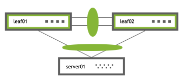
A basic MLAG configuration looks like this:
 |
|
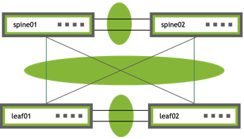
More elaborate configurations are also possible. The number of links between the host and the switches can be greater than two and does not have to be symmetrical. Additionally, because the two peer switches appear as a single switch to other bonding devices, you can also connect pairs of MLAG switches to each other in a switch-to-switch MLAG configuration:
 |
|
LACP and Dual-connected Links
Link Aggregation Control Protocol (LACP), the IEEE standard protocol for managing bonds, is used for verifying dual-connectedness. LACP runs on the dual-connected devices and on each of the MLAG peer switches. On a dual-connected device, the only configuration requirement is to create a bond that is managed by LACP.
On each of the peer switches, you must place the links that are connected to the dual-connected host or switch in the bond. This is true even if the links are a single port on each peer switch, where each port is placed into a bond, as shown below:
All of the dual-connected bonds on the peer switches have their system ID set to the MLAG system ID. Therefore, from the point of view of the hosts, each of the links in its bond is connected to the same system and so the host uses both links.
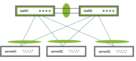
Each peer switch periodically makes a list of the LACP partner MAC addresses for all of their bonds and sends that list to its peer (using the clagd service). The LACP partner MAC address is the MAC address of the system at the other end of a bond (server01, server02, and server03 in the figure above). When a switch receives this list from its peer, it compares the list to the LACP partner MAC addresses on its switch. If any matches are found and the clag-id for those bonds match, then that bond is a dual-connected bond. You can find the LACP partner MAC address by the running net show bridge macs command.
Requirements
MLAG has these requirements:
- There must be a direct connection between the two peer switches configured with MLAG. This is typically a bond for increased reliability and bandwidth.
- There must be only two peer switches in one MLAG configuration, but you can have multiple configurations in a network for switch-to-switch MLAG.
- Both switches in the MLAG pair must be identical; they must both be the same model of switch and run the same Cumulus Linux release. See Upgrading Cumulus Linux.
- The dual-connected devices (servers or switches) can use LACP (IEEE 802.3ad or 802.1ax) to form the bond. In this case, the peer switches must also use LACP.
- Cumulus Linux does not support MLAG with 802.1X; the switch cannot synchronize 802.1X authenticated MAC addresses over the peerlink.
The Edgecore Minipack AS8000 and Cumulus Express CX-11128 switches do not support MLAG.
Basic Configuration
To configure MLAG, you need to create a bond that uses LACP on the dual-connected devices and configure the interfaces (including bonds, VLANs, bridges, and peer links) on each peer switch.
Follow these steps on each peer switch in the MLAG pair:
On the dual-connected device, such as a host or server that sends traffic to and from the switch, create a bond that uses LACP. The method you use varies with the type of device you are configuring.
If you cannot use LACP in your environment, you can configure the bonds in balance-xor mode.
Place every interface that connects to the MLAG pair from a dual-connected device into a bond, even if the bond contains only a single link on a single physical switch.
The following examples place swp1 in bond1 and swp2 in bond2. The examples also add a description for the bonds (an alias), which is optional.
cumulus@leaf01:~$ net add bond bond1 bond slaves swp1 cumulus@leaf01:~$ net add bond bond1 alias bond1 on swp1 cumulus@leaf01:~$ net add bond bond2 bond slaves swp2 cumulus@leaf01:~$ net add bond bond2 alias bond2 on swp2 cumulus@leaf01:~$ net pending cumulus@leaf01:~$ net commitAdd the following lines to the
/etc/network/interfacesfile:cumulus@leaf01:~$ sudo nano /etc/network/interfaces ... auto bond1 iface bond1 alias bond1 on swp1 bond-slaves swp1 ... auto bond2 iface bond2 alias bond2 on swp2 bond-slaves swp2 ...Add a unique MLAG ID (clag-id) to each bond.
You must specify a unique MLAG ID (clag-id) for every dual-connected bond on each peer switch so that switches know which links are dual-connected or are connected to the same host or switch. The value must be between 1 and 65535 and must be the same on both peer switches. A value of 0 disables MLAG on the bond.
The example commands below add an MLAG ID of 1 to bond1 and 2 to bond2:
cumulus@leaf01:~$ net add bond bond1 clag id 1 cumulus@leaf01:~$ net add bond bond2 clag id 2 cumulus@leaf01:~$ net pending cumulus@leaf01:~$ net commitIn the
/etc/network/interfacesfile, add the lineclag-id 1to theauto bond1stanza andclag-id 2toauto bond2stanza:cumulus@switch:~$ sudo nano /etc/network/interfaces ... auto bond1 iface bond1 alias bond1 on swp1 bond-slaves swp1 clag-id 1 auto bond2 iface bond2 alias bond2 on swp2 bond-slaves swp2 clag-id 2 ...Add the bonds you created above to a bridge. The example commands below add bond1 and bond2 to a VLAN-aware bridge.
On Mellanox switches, you must add all VLANs configured on the MLAG bond to the bridge so that traffic to the downstream device connected in MLAG is redirected successfully over the peerlink in case of an MLAG bond failure.
cumulus@leaf01:~$ net add bridge bridge ports bond1,bond2 cumulus@leaf01:~$ net pending cumulus@leaf01:~$ net commitEdit the
/etc/network/interfacesfile to add thebridge-ports bond1 bond2lines to theauto bridgestanza:cumulus@switch:~$ sudo nano /etc/network/interfaces ... auto bridge iface bridge bridge-ports bond1 bond2 bridge-vlan-aware yes ...Create the inter-chassis bond and the peer link VLAN (as a VLAN subinterface). You also need to provide the peer link IP address, the MLAG bond interfaces, the MLAG system MAC address, and the backup interface.
- By default, the NCLU command configures the inter-chassis bond with the name peerlink and the peer link VLAN with the name peerlink.4094. Use peerlink.4094 to ensure that the VLAN is independent of the bridge and spanning tree forwarding decisions.
- The peer link IP address is an unrouteable link-local address that provides layer 3 connectivity between the peer switches.
- Cumulus Linux provides a reserved range of MAC addresses for MLAG (between 44:38:39:ff:00:00 and 44:38:39:ff:ff:ff). Use a MAC address from this range to prevent conflicts with other interfaces in the same bridged network.
- Do not to use a multicast MAC address.
- Do not use the same MAC address for different MLAG pairs; make sure you specify a different MAC address for each MLAG pair in the network.
- The backup IP address is any layer 3 backup interface for the peer link, which is used in case the peer link goes down. The backup IP address is required and must be different than the peer link IP address. It must be reachable by a route that does not use the peer link. Use the loopback or management IP address of the switch.
The following examples show commands for both MLAG peers (leaf01 and leaf02).
The NCLU command is a macro command that:
- Automatically creates the inter-chassis bond (
peerlink) and the peer link VLAN subinterface (peerlink.4094), and adds thepeerlinkbond to the bridge - Configures the peer link IP address (
primaryis the link-local address) - Adds the MLAG system MAC address, the MLAG bond interfaces, and the backup IP address you specify
cumulus@leaf01:~$ net add clag peer sys-mac 44:38:39:BE:EF:AA interface swp49-50 primary backup-ip 10.10.10.2
cumulus@leaf01:~$ net pending
cumulus@leaf01:~$ net commit
To configure the backup link to a VRF, include the name of the VRF with the
backup-ipparameter. The following example configures the backup link to VRF RED:cumulus@leaf01:~$ net add clag peer sys-mac 44:38:39:BE:EF:AA interface swp49-50 primary backup-ip 10.10.10.2 vrf RED cumulus@leaf01:~$ net pending cumulus@leaf01:~$ net commitcumulus@leaf02:~$ net add clag peer sys-mac 44:38:39:BE:EF:AA interface swp49-50 primary backup-ip 10.10.10.1 cumulus@leaf02:~$ net pending cumulus@leaf02:~$ net commitTo configure the backup link to a VRF, include the name of the VRF with the
backup-ipparameter. The following example configures the backup link to VRF RED:cumulus@leaf02:~$ net add clag peer sys-mac 44:38:39:BE:EF:AA interface swp49-50 primary backup-ip 10.10.10.1 vrf RED cumulus@leaf02:~$ net pending cumulus@leaf02:~$ net commitEdit the
/etc/network/interfacesfile to add the following parameters, then run thesudo ifreload -acommand.- The inter-chasis bond (
peerlink) with two ports in the bond (swp49 and swp50 in the example command below) - The
peerlinkbond to the bridge - The peer link VLAN (
peerlink.4094) with the backup IP address, the peer link IP address (link-local), and the MLAG system MAC address (from the reserved range of addresses).
cumulus@leaf01:~$ sudo nano /etc/network/interfaces ... auto bridge iface bridge bridge-ports bond1 bond2 peerlink bridge-vlan-aware yes ... auto peerlink iface peerlink bond-slaves swp49 swp50auto peerlink.4094 iface peerlink.4094 clagd-backup-ip 10.10.10.2 clagd-peer-ip linklocal clagd-sys-mac 44:38:39:BE:EF:AA …
To configure the backup link to a VRF, include the name of the VRF with the
clagd-backup-ipparameter. The following example configures the backup link to VRF RED:cumulus@leaf01:~$ sudo nano /etc/network/interfaces ... auto peerlink.4094 iface peerlink.4094 clagd-backup-ip 10.10.10.2 vrf RED clagd-peer-ip linklocal clagd-sys-mac 44:38:39:BE:EF:AA ...Run the
sudo ifreload -acommand to apply all the configuration changes:cumulus@leaf01:~$ sudo ifreload -acumulus@leaf02:~$ sudo nano /etc/network/interfaces ... auto bridge iface bridge bridge-ports bond1 bond2 peerlink bridge-vlan-aware yes ... auto peerlink iface peerlink bond-slaves swp49 swp50auto peerlink.4094 iface peerlink.4094 clagd-backup-ip 10.10.10.1 clagd-peer-ip linklocal clagd-sys-mac 44:38:39:BE:EF:AA …
To configure the backup link to a VRF, include the name of the VRF with the
clagd-backup-ipparameter. The following example configures the backup link to VRF RED:cumulus@leaf02:~$ sudo nano /etc/network/interfaces ... auto peerlink.4094 iface peerlink.4094 clagd-backup-ip 10.10.10.1 vrf RED clagd-peer-ip linklocal clagd-sys-mac 44:38:39:BE:EF:AA ...Run the
sudo ifreload -acommand to apply all the configuration changes:cumulus@leaf02:~$ sudo ifreload -a
- Do not add VLAN 4094 to the bridge VLAN list; VLAN 4094 for the peer link subinterface cannot be configured as a bridged VLAN with bridge VIDs under the bridge.
- Do not use 169.254.0.1 as the MLAG peer link IP address; Cumulus Linux uses this address exclusively for BGP unnumbered interfaces.
- When you configure MLAG manually in the
/etc/network/interfacesfile, the changes take effect when you bring the peer link interface up with thesudo ifreload -acommand. Do not usesystemctl restart clagd.serviceto apply the new configuration. - The MLAG bond does not support layer 3 configuration.
MLAG synchronizes the dynamic state between the two peer switches but it does not synchronize the switch configurations. After modifying the configuration of one peer switch, you must make the same changes to the configuration on the other peer switch. This applies to all configuration changes, including:
- Port configuration, such as VLAN membership, MTU and bonding parameters.
- Bridge configuration, such as spanning tree parameters or bridge properties.
- Static address entries, such as static FDB entries and static IGMP entries.
- QoS configuration, such as ACL entries.
Optional Configuration
This section describes optional configuration procedures.
Set Roles and Priority
Each MLAG-enabled switch in the pair has a role. When the peering relationship is established between the two switches, one switch is put into the primary role and the other into the secondary role. When an MLAG-enabled switch is in the secondary role, it does not send STP BPDUs on dual-connected links; it only sends BPDUs on single-connected links. The switch in the primary role sends STP BPDUs on all single- and dual-connected links.
By default, the role is determined by comparing the MAC addresses of the two sides of the peering link; the switch with the lower MAC address assumes the primary role. You can override this by setting the priority option for the peer link:
cumulus@leaf01:~$ net add interface peerlink.4094 clag priority 2048
cumulus@leaf01:~$ net pending
cumulus@leaf01:~$ net commit
Edit the /etc/network/interfaces file and add the clagd-priority option, then run the ifreload -a command.
cumulus@switch:~$ sudo nano /etc/network/interfaces
...
auto peerlink.4094
iface peerlink.4094
    clagd-peer-ip linklocal
    clagd-backup-ip 10.10.10.2
    clagd-sys-mac 44:38:39:BE:EF:AA
    clagd-priority 2048
...
cumulus@switch:~$ sudo ifreload -a
The switch with the lower priority value is given the primary role; the default value is 32768 and the range is between 0 and 65535.
When the clagd service exits during switch reboot or if you stop the service on the primary switch, the peer switch that is in the secondary role becomes the primary.
However, if the primary switch goes down without stopping the clagd service for any reason, or if the peer link goes down, the secondary switch does not change its role. If the peer switch is determined to not be alive, the switch in the secondary role rolls back the LACP system ID to be the bond interface MAC address instead of the MLAG system MAC address (clagd-sys-mac) and the switch in primary role uses the MLAG system MAC address as the LACP system ID on the bonds.
Set clagctl Timers
The clagd service has a number of timers that you can tune for enhanced performance:
Timer | Description |
|---|---|
--reloadTimer <seconds> | The number of seconds to wait for the peer switch to become active. If the peer switch does not become active after the timer expires, the MLAG bonds leave the initialization (protodown) state and become active. This provides clagd with sufficient time to determine whether the peer switch is coming up or if it is permanently unreachable.The default is 300 seconds. |
--peerTimeout <seconds> | The number of seconds clagd waits without receiving any messages from the peer switch before it determines that the peer is no longer active. At this point, the switch reverts all configuration changes so that it operates as a standard non-MLAG switch. This includes removing all statically assigned MAC addresses, clearing the egress forwarding mask, and allowing addresses to move from any port to the peer port. After a message is again received from the peer, MLAG operation restarts. If this parameter is not specified, clagd uses ten times the local lacpPoll value. |
--initDelay <seconds> | The number of seconds clagd delays bringing up MLAG bonds and anycast IP addresses.The default is 180 seconds.NVIDIA recommends you set this parameter to 300 seconds in a scaled environment. |
--sendTimeout <seconds> | The number of seconds clagd waits until the sending socket times out. If it takes longer than the sendTimeout value to send data to the peer, clagd generates an exception.The default is 30 seconds. |
--lacpPoll <seconds> | The number of seconds clagd waits before obtaining local LACP information.The default is 2 seconds. |
To set a timer:
Run the net add interface peerlink.4094 clag args <timer> <value> command. The following example command sets the peerlink timer to 900 seconds:
cumulus@leaf01:~$ net add interface peerlink.4094 clag args --peerTimeout 900
cumulus@leaf01:~$ net pending
cumulus@leaf01:~$ net commit
Edit the /etc/network/interfaces file to add the clagd-args <timer> <value> line to the peerlink.4094 stanza, then run the ifreload -a command. The following example sets the peerlink timer to 900 seconds:
cumulus@switch:~$ sudo nano /etc/network/interfaces
...
auto peerlink.4094
iface peerlink.4094
    clagd-args --peerTimeout 900
    clagd-peer-ip linklocal
    clagd-backup-ip 10.10.10.2
    clagd-sys-mac 44:38:39:BE:EF:AA
    clagd-priority 2048
...
cumulus@switch:~$ sudo ifreload -a
Configure MLAG with a Traditional Mode Bridge
To configure MLAG with a traditional mode bridge instead of a VLAN-aware mode bridge, you must configure the peer link and all dual-connected links as untagged (native) ports on a bridge (note the absence of any VLANs in the bridge-ports line and the lack of the bridge-vlan-aware parameter below):
...
auto br0
iface br0
    bridge-ports peerlink bond1 bond2
...
The following example shows you how to allow VLAN 10 across the peer link:
...
auto br0.10
iface br0.10
    bridge-ports peerlink.10 bond1.10 bond2.10
    bridge-stp on
...
In an MLAG and traditional bridge configuration, NVIDIA recommends that you set bridge learning to off on all VLANs over the peerlink except for the layer 3 peerlink subinterface; for example:
...
auto peerlink
iface peerlink
    bridge-learning off

auto peerlink.1510
iface peerlink.1510
    bridge-learning off

auto peerlink.4094
iface peerlink.4094
...
Configure a Backup UDP Port
By default, Cumulus Linux uses UDP port 5342 with the backup IP address. To change the backup UDP port:
cumulus@leaf01:~$ net add interface peerlink.4094 clag args --backupPort 5400
cumulus@leaf01:~$ net pending
cumulus@leaf01:~$ net commit
Edit the /etc/network/interfaces file to add clagd-args --backupPort <port> to the auto peerlink.4094 stanza. For example:
...
auto peerlink.4094
iface peerlink.4094
    clagd-args --backupPort 5400
    clagd-backup-ip 10.10.10.2
    clagd-peer-ip linklocal
    clagd-sys-mac 44:38:39:BE:EF:AA
...
Run the sudo ifreload -a command to apply all the configuration changes:
cumulus@leaf01:~$ sudo ifreload -a
Best Practices
Follow these best practices when configuring MLAG on your switches.
MTU and MLAG
The MTU in MLAG traffic is determined by the bridge MTU. Bridge MTU is determined by the lowest MTU setting of an interface that is a member of the bridge. If you want to set an MTU other than the default of 9216 bytes, you must configure the MTU on each physical interface and bond interface that is a member of every MLAG bridge in the entire bridged domain.
The following example commands set an MTU of 1500 for each of the bond interfaces (peerlink, uplink, bond1, bond2), which are members of bridge bridge:
cumulus@switch:~$ net add bond peerlink mtu 1500
cumulus@switch:~$ net add bond uplink mtu 1500
cumulus@switch:~$ net add bond bond1 mtu 1500
cumulus@switch:~$ net add bond bond2 mtu 1500
cumulus@switch:~$ net pending
cumulus@switch:~$ net commit
Edit the /etc/network/interfaces file, then run the ifreload -a command. For example:
cumulus@switch:~$ sudo nano /etc/network/interfaces
...
auto bridge
iface bridge
    bridge-ports peerlink uplink bond1 bond2

auto peerlink
iface peerlink
    mtu 1500

auto bond1
iface bond1
    mtu 1500

auto bond2
iface bond2
    mtu 1500

auto uplink
iface uplink
    mtu 1500
...
cumulus@switch:~$ sudo ifreload -a
STP and MLAG
Always enable STP in your layer 2 network and BPDU Guard on the host-facing bond interfaces.
- The STP global configuration must be the same on both peer switches.
- The STP configuration for dual-connected ports must be the same on both peer switches.
- The STP priority must be the same on both peer switches.
- To minimize convergence times when a link transitions to the forwarding state, configure the edge ports (for tagged and untagged frames) with PortAdminEdge and BPDU guard enabled.
- Do not use a multicast MAC address for the LACP ID on systems connected to MLAG bonds; the switch drops STP BPDUs from a multicast MAC address.
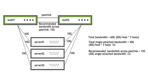
Peer Link Sizing
The peer link carries very little traffic when compared to the bandwidth consumed by dataplane traffic. In a typical MLAG configuration, most every connection between the two switches in the MLAG pair is dual-connected so the only traffic going across the peer link is traffic from the clagd process and some LLDP or LACP traffic; the traffic received on the peer link is not forwarded out of the dual-connected bonds.
However, there are some instances where a host is connected to only one switch in the MLAG pair; for example:
- You have a hardware limitation on the host where there is only one PCIE slot, and therefore, one NIC on the system, so the host is only single-connected across that interface.
- The host does not support 802.3ad and you cannot create a bond on it.
- You are accounting for a link failure, where the host becomes single connected until the failure is resolved.
etermine how much bandwidth is traveling across the single-connected interfaces and allocate half of that bandwidth to the peer link. On average, one half of the traffic destined to the single-connected host arrives on the switch directly connected to the single-connected host and the other half arrives on the switch that is not directly connected to the single-connected host. When this happens, only the traffic that arrives on the switch that is not directly connected to the single-connected host needs to traverse the peer link.
In addition, you might want to add extra links to the peer link bond to handle link failures in the peer link bond itself.
 |
|
When planning for link failures for a full rack, you need only allocate enough bandwidth to meet your site strategy for handling failure scenarios. For example, for a full rack with 40 servers and two switches, you might plan for four to six servers to lose connectivity to a single switch and become single connected before you respond to the event. Therefore, if you have 40 hosts each with 20G of bandwidth dual-connected to the MLAG pair, you might allocate between 20G and 30G of bandwidth to the peer link, which accounts for half of the single-connected bandwidth for four to six hosts.
Peer Link Routing
When enabling a routing protocol in an MLAG environment, it is also necessary to manage the uplinks; by default MLAG is not aware of layer 3 uplink interfaces. If there is a peer link failure, MLAG does not remove static routes or bring down a BGP or OSPF adjacency unless you use a separate link state daemon such as ifplugd.
When you use MLAG with VRR, set up a routed adjacency across the peerlink.4094 interface. If a routed connection is not built across the peer link, during an uplink failure on one of the switches in the MLAG pair, egress traffic might not be forwarded if the destination is on the switch whose uplinks are down.
To set up the adjacency, configure a BGP or OSPF unnumbered peering, as appropriate for your network.
For BGP, use a configuration like this:
cumulus@switch:~$ net add bgp neighbor peerlink.4094 interface remote-as internal
cumulus@switch:~$ net commit
For OSPF, use a configuration like this:
cumulus@switch:~$ net add interface peerlink.4094 ospf area 0.0.0.1
cumulus@switch:~$ net commit
If you are using EVPN and MLAG, you need to enable the EVPN address family across the peerlink.4094 interface as well:
cumulus@switch:~$ net add bgp neighbor peerlink.4094 interface remote-as internal
cumulus@switch:~$ net add bgp l2vpn evpn neighbor peerlink.4094 activate
cumulus@switch:~$ net commit
If you use NCLU to create an iBGP peering across the peer link, the net add bgp l2vpn evpn neighbor peerlink.4094 activate command creates a new eBGP neighborship when one is already configured for iBGP. The existing iBGP configuration is still valid.
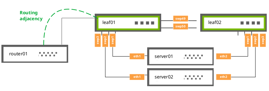
MLAG Routing Support
In addition to the routing adjacency over the peer link, Cumulus Linux supports routing adjacencies from attached network devices to MLAG switches under the following conditions:
- The router must physically attach to a single interface of a switch.
- The attached router must peer directly to a local address on the physically connected switch.
The router cannot:
- Attach to the switch over a MLAG bond interface.
- Form routing adjacencies to a virtual address (VRR or VRRP).
Configuration Examples
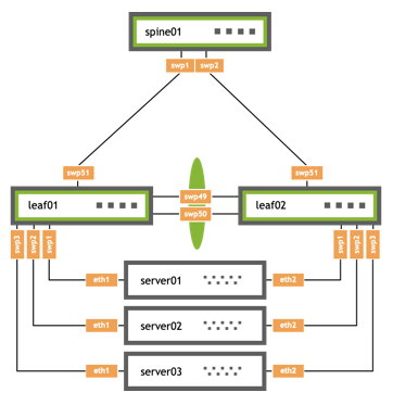
Basic Example
The example below shows a basic MLAG configuration, where:
- leaf01 and leaf02 are MLAG peers
- Three bonds are configured for MLAG, each with a single port, a peer link that is a bond with two member ports, and three VLANs on each port
cumulus@leaf01:~$ cat /etc/network/interfaces

auto lo
iface lo inet loopback
    address 10.10.10.1/32

auto mgmt
iface mgmt
    vrf-table auto
    address 127.0.0.1/8
    address ::1/128

auto eth0
iface eth0 inet dhcp
    vrf mgmt

auto bridge
iface bridge
    bridge-ports peerlink
    bridge-ports bond1 bond2 bond3
    bridge-vids 10 20 30
    bridge-vlan-aware yes

auto vlan10
iface vlan10
    address 10.1.10.2/24
    vlan-raw-device bridge
    vlan-id 10

auto vlan20
iface vlan20
    address 10.1.20.2/24
    vlan-raw-device bridge
    vlan-id 20

auto vlan30
iface vlan30
    address 10.1.30.2/24
    vlan-raw-device bridge
    vlan-id 30

auto swp51
iface swp51
    alias leaf to spine

auto swp49
iface swp49
    alias peerlink

auto swp50
iface swp50
    alias peerlink

auto peerlink
iface peerlink
    bond-slaves swp49 swp50

auto peerlink.4094
iface peerlink.4094
    clagd-backup-ip 10.10.10.2
    clagd-peer-ip linklocal
    clagd-priority 1000
    clagd-sys-mac 44:38:39:BE:EF:AA

auto swp1
iface swp1
    alias bond member of bond1
    mtu 9000

auto bond1
iface bond1
    alias bond1 on swp1
    mtu 9000
    clag-id 1
    bridge-access 10
    bond-slaves swp1
    bond-lacp-bypass-allow yes
    mstpctl-bpduguard yes
    mstpctl-portadminedge yes

auto swp2
iface swp2
    alias bond member of bond2
    mtu 9000

auto bond2
iface bond2
    alias bond2 on swp2
    mtu 9000
    clag-id 2
    bridge-access 20
    bond-slaves swp2
    bond-lacp-bypass-allow yes
    mstpctl-bpduguard yes
    mstpctl-portadminedge yes

auto swp3
iface swp3
    alias bond member of bond3
    mtu 9000

auto bond3
iface bond3
    alias bond3 on swp3
    mtu 9000
    clag-id 3
    bridge-access 30
    bond-slaves swp3
    bond-lacp-bypass-allow yes
    mstpctl-bpduguard yes
    mstpctl-portadminedge yes
cumulus@leaf02:~$ cat /etc/network/interfaces

auto lo
iface lo inet loopback
    address 10.10.10.2/32

auto mgmt
iface mgmt
    vrf-table auto
    address 127.0.0.1/8
    address ::1/128

auto eth0
iface eth0 inet dhcp
    vrf mgmt

auto bridge
iface bridge
    bridge-ports peerlink
    bridge-ports bond1 bond2 bond3
    bridge-vids 10 20 30
    bridge-vlan-aware yes

auto vlan10
iface vlan10
    address 10.1.10.3/24
    vlan-raw-device bridge
    vlan-id 10

auto vlan20
iface vlan20
    address 10.1.20.3/24
    vlan-raw-device bridge
    vlan-id 20

auto vlan30
iface vlan30
    address 10.1.30.3/24
    vlan-raw-device bridge
    vlan-id 30

auto swp51
iface swp51
    alias leaf to spine

auto swp49
iface swp49
    alias peerlink

auto swp50
iface swp50
    alias peerlink

auto peerlink
iface peerlink
    bond-slaves swp49 swp50

auto peerlink.4094
iface peerlink.4094
    clagd-backup-ip 10.10.10.1
    clagd-peer-ip linklocal
    clagd-priority 32768
    clagd-sys-mac 44:38:39:BE:EF:AA

auto swp1
iface swp1
    alias bond member of bond1
    mtu 9000

auto bond1
iface bond1
    alias bond1 on swp1
    mtu 9000
    clag-id 1
    bridge-access 10
    bond-slaves swp1
    bond-lacp-bypass-allow yes
    mstpctl-bpduguard yes
    mstpctl-portadminedge yes

auto swp2
iface swp2
    alias bond member of bond2
    mtu 9000

auto bond2
iface bond2
    alias bond2 on swp2
    mtu 9000
    clag-id 2
    bridge-access 20
    bond-slaves swp2
    bond-lacp-bypass-allow yes
    mstpctl-bpduguard yes
    mstpctl-portadminedge yes

auto swp3
iface swp3
    alias bond member of bond3
    mtu 9000

auto bond3
iface bond3
    alias bond3 on swp3
    mtu 9000
    clag-id 3
    bridge-access 30
    bond-slaves swp3
    bond-lacp-bypass-allow yes
    mstpctl-bpduguard yes
    mstpctl-portadminedge yes
cumulus@spine01:~$ cat /etc/network/interfaces

auto lo
iface lo inet loopback
    address 10.10.10.101/32

auto mgmt
iface mgmt
    vrf-table auto
    address 127.0.0.1/8
    address ::1/128

auto eth0
iface eth0 inet dhcp
    vrf mgmt

auto swp1
iface swp1
    alias leaf to spine

auto swp2
iface swp2
    alias leaf to spine
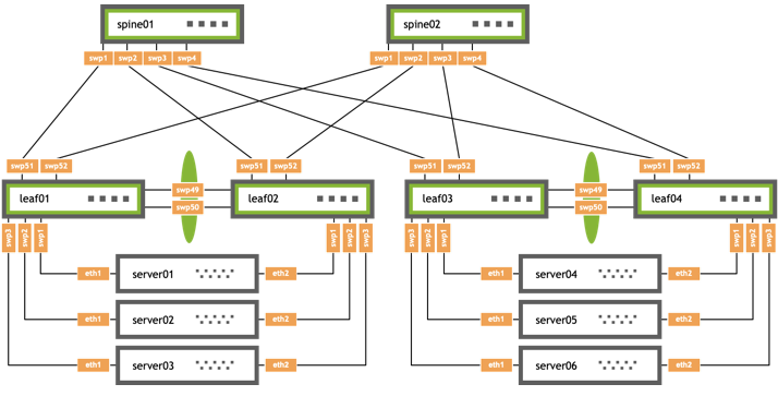
MLAG and BGP Example
The example configuration below shows an MLAG configuration where:
- leaf01 and leaf02 are MLAG peers, and leaf03 and leaf04 are are MLAG peers
- Three bonds are configured for MLAG, each with a single port, a peer link that is a bond with two member ports, and three VLANs on each port
- BGP unnumbered is configured on the leafs and spines with a routed adjacency across the
peerlink.4094interface
/etc/network/interfaces
cumulus@leaf01:~$ cat /etc/network/interfaces
auto lo
iface lo inet loopback
    address 10.10.10.1/32

auto mgmt
iface mgmt
    vrf-table auto
    address 127.0.0.1/8
    address ::1/128

auto eth0
iface eth0 inet dhcp
    vrf mgmt

auto bridge
iface bridge
    bridge-ports peerlink
    bridge-ports bond1 bond2 bond3
    bridge-vids 10 20 30
    bridge-vlan-aware yes

auto vlan10
iface vlan10
    address 10.1.10.2/24
    vlan-raw-device bridge
    vlan-id 10

auto vlan20
iface vlan20
    address 10.1.20.2/24
    vlan-raw-device bridge
    vlan-id 20

auto vlan30
iface vlan30
    address 10.1.30.2/24
    vlan-raw-device bridge
    vlan-id 30

auto swp51
iface swp51
    alias leaf to spine

auto swp52
iface swp52
    alias leaf to spine

auto swp49
iface swp49
    alias peerlink

auto swp50
iface swp50
    alias peerlink

auto peerlink
iface peerlink
    bond-slaves swp49 swp50

auto peerlink.4094
iface peerlink.4094
    clagd-backup-ip 10.10.10.2
    clagd-peer-ip linklocal
    clagd-priority 1000
    clagd-sys-mac 44:38:39:BE:EF:AA

auto swp1
iface swp1
    alias bond member of bond1
    mtu 9000

auto bond1
iface bond1
    alias bond1 on swp1
    mtu 9000
    clag-id 1
    bridge-access 10
    bond-slaves swp1
    bond-lacp-bypass-allow yes
    mstpctl-bpduguard yes
    mstpctl-portadminedge yes

auto swp2
iface swp2
    alias bond member of bond2
    mtu 9000

auto bond2
iface bond2
    alias bond2 on swp2
    mtu 9000
    clag-id 2
    bridge-access 20
    bond-slaves swp2
    bond-lacp-bypass-allow yes
    mstpctl-bpduguard yes
    mstpctl-portadminedge yes

auto swp3
iface swp3
    alias bond member of bond3
    mtu 9000

auto bond3
iface bond3
    alias bond3 on swp3
    mtu 9000
    clag-id 3
    bridge-access 30
    bond-slaves swp3
    bond-lacp-bypass-allow yes
    mstpctl-bpduguard yes
    mstpctl-portadminedge yes
cumulus@leaf02:~$ cat /etc/network/interfaces
auto lo
iface lo inet loopback
    address 10.10.10.2/32

auto mgmt
iface mgmt
    vrf-table auto
    address 127.0.0.1/8
    address ::1/128


auto eth0
iface eth0 inet dhcp
    vrf mgmt

auto bridge
iface bridge
    bridge-ports peerlink
    bridge-ports bond1 bond2 bond3
    bridge-vids 10 20 30
    bridge-vlan-aware yes

auto vlan10
iface vlan10
    address 10.1.10.3/24
    vlan-raw-device bridge
    vlan-id 10

auto vlan20
iface vlan20
    address 10.1.20.3/24
    vlan-raw-device bridge
    vlan-id 20

auto vlan30
iface vlan30
    address 10.1.30.3/24
    vlan-raw-device bridge
    vlan-id 30

auto swp51
iface swp51
    alias leaf to spine

auto swp52
iface swp52
    alias leaf to spine

auto swp49
iface swp49
    alias peerlink

auto swp50
iface swp50
    alias peerlink

auto peerlink
iface peerlink
    bond-slaves swp49 swp50

auto peerlink.4094
iface peerlink.4094
    clagd-backup-ip 10.10.10.1
    clagd-peer-ip linklocal
    clagd-priority 32768
    clagd-sys-mac 44:38:39:BE:EF:AA

auto swp1
iface swp1
    alias bond member of bond1
    mtu 9000

auto bond1
iface bond1
    alias bond1 on swp1
    mtu 9000
    clag-id 1
    bridge-access 10
    bond-slaves swp1
    bond-lacp-bypass-allow yes
    mstpctl-bpduguard yes
    mstpctl-portadminedge yes

auto swp2
iface swp2
    alias bond member of bond2
    mtu 9000

auto bond2
iface bond2
    alias bond2 on swp2
    mtu 9000
    clag-id 2
    bridge-access 20
    bond-slaves swp2
    bond-lacp-bypass-allow yes
    mstpctl-bpduguard yes
    mstpctl-portadminedge yes

auto swp3
iface swp3
    alias bond member of bond3
    mtu 9000

auto bond3
iface bond3
    alias bond3 on swp3
    mtu 9000
    clag-id 3
    bridge-access 30
    bond-slaves swp3
    bond-lacp-bypass-allow yes
    mstpctl-bpduguard yes
    mstpctl-portadminedge yes
cumulus@leaf03:~$ cat /etc/network/interfaces
auto lo
iface lo inet loopback
    address 10.10.10.3/32

auto mgmt
iface mgmt
    vrf-table auto
    address 127.0.0.1/8
    address ::1/128


auto eth0
iface eth0 inet dhcp
    vrf mgmt

auto bridge
iface bridge
    bridge-ports peerlink
    bridge-ports bond1 bond2 bond3
    bridge-vids 10 20 30
    bridge-vlan-aware yes

auto vlan10
iface vlan10
    address 10.1.10.2/24
    vlan-raw-device bridge
    vlan-id 10

auto vlan20
iface vlan20
    address 10.1.20.2/24
    vlan-raw-device bridge
    vlan-id 20

auto vlan30
iface vlan30
    address 10.1.30.2/24
    vlan-raw-device bridge
    vlan-id 30

auto swp51
iface swp51
    alias leaf to spine

auto swp52
iface swp52
    alias leaf to spine

auto swp49
iface swp49
    alias peerlink

auto swp50
iface swp50
    alias peerlink

auto peerlink
iface peerlink
    bond-slaves swp49 swp50

auto peerlink.4094
iface peerlink.4094
    clagd-backup-ip 10.10.10.4
    clagd-peer-ip linklocal
    clagd-priority 1000
    clagd-sys-mac 44:38:39:BE:EF:BB

auto swp1
iface swp1
    alias bond member of bond1
    mtu 9000

auto bond1
iface bond1
    alias bond1 on swp1
    mtu 9000
    clag-id 1
    bridge-access 10
    bond-slaves swp1
    bond-lacp-bypass-allow yes
    mstpctl-bpduguard yes
    mstpctl-portadminedge yes

auto swp2
iface swp2
    alias bond member of bond2
    mtu 9000

auto bond2
iface bond2
    alias bond2 on swp2
    mtu 9000
    clag-id 2
    bridge-access 20
    bond-slaves swp2
    bond-lacp-bypass-allow yes
    mstpctl-bpduguard yes
    mstpctl-portadminedge yes

auto swp3
iface swp3
    alias bond member of bond3
    mtu 9000

auto bond3
iface bond3
    alias bond3 on swp3
    mtu 9000
    clag-id 3
    bridge-access 30
    bond-slaves swp3
    bond-lacp-bypass-allow yes
    mstpctl-bpduguard yes
    mstpctl-portadminedge yes
cumulus@leaf04:~$ cat /etc/network/interfaces
auto lo
iface lo inet loopback
    address 10.10.10.4/32

auto mgmt
iface mgmt
    vrf-table auto
    address 127.0.0.1/8
    address ::1/128

auto eth0
iface eth0 inet dhcp
    vrf mgmt

auto bridge
iface bridge
    bridge-ports peerlink
    bridge-ports bond1 bond2 bond3
    bridge-vids 10 20 30
    bridge-vlan-aware yes

auto vlan10
iface vlan10
    address 10.1.10.3/24
    vlan-raw-device bridge
    vlan-id 10

auto vlan20
iface vlan20
    address 10.1.20.3/24
    vlan-raw-device bridge
    vlan-id 20

auto vlan30
iface vlan30
    address 10.1.30.3/24
    vlan-raw-device bridge
    vlan-id 30

auto swp51
iface swp51
    alias leaf to spine

auto swp52
iface swp52
    alias leaf to spine

auto swp49
iface swp49
    alias peerlink

auto swp50
iface swp50
    alias peerlink

auto peerlink
iface peerlink
    bond-slaves swp49 swp50

auto peerlink.4094
iface peerlink.4094
    clagd-backup-ip 10.10.10.3
    clagd-peer-ip linklocal
    clagd-priority 32768
    clagd-sys-mac 44:38:39:BE:EF:BB

auto swp1
iface swp1
    alias bond member of bond1
    mtu 9000

auto bond1
iface bond1
    alias bond1 on swp1
    mtu 9000
    clag-id 1
    bridge-access 10
    bond-slaves swp1
    bond-lacp-bypass-allow yes
    mstpctl-bpduguard yes
    mstpctl-portadminedge yes

auto swp2
iface swp2
    alias bond member of bond2
    mtu 9000

auto bond2
iface bond2
    alias bond2 on swp2
    mtu 9000
    clag-id 2
    bridge-access 20
    bond-slaves swp2
    bond-lacp-bypass-allow yes
    mstpctl-bpduguard yes
    mstpctl-portadminedge yes

auto swp3
iface swp3
    alias bond member of bond3
    mtu 9000

auto bond3
iface bond3
    alias bond3 on swp3
    mtu 9000
    clag-id 3
    bridge-access 30
    bond-slaves swp3
    bond-lacp-bypass-allow yes
    mstpctl-bpduguard yes
    mstpctl-portadminedge yes
cumulus@spine01:~$ cat /etc/network/interfaces
auto lo
iface lo inet loopback
    address 10.10.10.101/32

auto mgmt
iface mgmt
    vrf-table auto
    address 127.0.0.1/8
    address ::1/128

auto eth0
iface eth0 inet dhcp
    vrf mgmt
auto swp1
iface swp1
    alias leaf to spine

auto swp2
iface swp2
    alias leaf to spine

auto swp3
iface swp3
    alias leaf to spine

auto swp4
iface swp4
    alias leaf to spine
cumulus@spine02:~$ cat /etc/network/interfaces
auto lo
iface lo inet loopback
    address 10.10.10.102/32

auto mgmt
iface mgmt
    vrf-table auto
    address 127.0.0.1/8
    address ::1/128

auto eth0
iface eth0 inet dhcp
    vrf mgmt

auto swp1
iface swp1
    alias leaf to spine

auto swp2
iface swp2
    alias leaf to spine

auto swp3
iface swp3
    alias leaf to spine

auto swp4
iface swp4
    alias leaf to spine
/etc/frr/frr.conf
cumulus@leaf01:~$ cat /etc/frr/frr.conf
...
service integrated-vtysh-config
!
log syslog informational
!
router bgp 65101
 bgp router-id 10.10.10.1
 bgp bestpath as-path multipath-relax
 neighbor underlay peer-group
 neighbor underlay remote-as external
 neighbor peerlink.4094 interface remote-as internal
 neighbor swp51 interface peer-group underlay
 neighbor swp52 interface peer-group underlay
 !
 !
 address-family ipv4 unicast
  redistribute connected
 exit-address-family
 !
!
line vty
!
cumulus@leaf02:~$ cat /etc/frr/frr.conf
...
service integrated-vtysh-config
!
log syslog informational
!
router bgp 65101
 bgp router-id 10.10.10.2
 bgp bestpath as-path multipath-relax
 neighbor underlay peer-group
 neighbor underlay remote-as external
 neighbor peerlink.4094 interface remote-as internal
 neighbor swp51 interface peer-group underlay
 neighbor swp52 interface peer-group underlay
 !
 !
 address-family ipv4 unicast
  redistribute connected
 exit-address-family
 !
!

!
line vty
!
cumulus@leaf03:~$ cat /etc/frr/frr.conf
...
service integrated-vtysh-config
!
log syslog informational
!
router bgp 65102
 bgp router-id 10.10.10.3
 bgp bestpath as-path multipath-relax
 neighbor underlay peer-group
 neighbor underlay remote-as external
 neighbor peerlink.4094 interface remote-as internal
 neighbor swp51 interface peer-group underlay
 neighbor swp52 interface peer-group underlay
 !
 !
 address-family ipv4 unicast
  redistribute connected
 exit-address-family
!

!
line vty
!
cumulus@leaf04:~$ cat /etc/frr/frr.conf
...
service integrated-vtysh-config
!
log syslog informational
!
router bgp 65102
 bgp router-id 10.10.10.4
 bgp bestpath as-path multipath-relax
 neighbor underlay peer-group
 neighbor underlay remote-as external
 neighbor peerlink.4094 interface remote-as internal
 neighbor swp51 interface peer-group underlay
 neighbor swp52 interface peer-group underlay
 !
 !
 address-family ipv4 unicast
  redistribute connected
 exit-address-family
 !

!
line vty
!
cumulus@spine01:~$ cat /etc/frr/frr.conf
...
service integrated-vtysh-config
!
log syslog informational
!
!
router bgp 65199
 bgp router-id 10.10.10.101
 bgp bestpath as-path multipath-relax
 neighbor underlay peer-group
 neighbor underlay remote-as external
 neighbor swp1 interface peer-group underlay
 neighbor swp2 interface peer-group underlay
 neighbor swp3 interface peer-group underlay
 neighbor swp4 interface peer-group underlay
 !
 !
 address-family ipv4 unicast
  redistribute connected
 exit-address-family
!

!
line vty
!
cumulus@spine02:~$ cat /etc/frr/frr.conf
...
service integrated-vtysh-config
!
log syslog informational
!
!
router bgp 65199
 bgp router-id 10.10.10.102
 bgp bestpath as-path multipath-relax
 neighbor underlay peer-group
 neighbor underlay remote-as external
 neighbor swp1 interface peer-group underlay
 neighbor swp2 interface peer-group underlay
 neighbor swp3 interface peer-group underlay
 neighbor swp4 interface peer-group underlay
 !
 !
 address-family ipv4 unicast
  redistribute connected
 exit-address-family
!

!
line vty
!
Troubleshooting
Use the following troubleshooting tips to check that MLAG is configured and working correctly.
Check MLAG Status
To check the status of your MLAG configuration, run the NCLU net show clag command or the Linux clagctl command. For example:
cumulus@switch:~$ net show clag
The peer is alive
    Peer Priority, ID, and Role: 4096 44:38:39:FF:00:01 primary
     Our Priority, ID, and Role: 8192 44:38:39:FF:00:02 secondary
          Peer Interface and IP: peerlink.4094 linklocal
                      Backup IP: 192.168.1.12 (inactive)
                     System MAC: 44:38:39:FF:00:01

CLAG Interfaces
Our Interface      Peer Interface     CLAG Id   Conflicts              Proto-Down Reason
----------------   ----------------   -------   --------------------   -----------------
           bond1   bond1              1         -                      -
           bond2   bond2              2         -                      -
Show All MLAG Settings
To see all MLAG settings, run the clagctl params command:
cumulus@leaf01:~$ clagctl params
clagVersion = 1.4.0
clagDataVersion = 1.4.0
clagCmdVersion = 1.1.0
peerIp = linklocal
peerIf = peerlink.4094
sysMac = 44:38:39:be:ef:aa
lacpPoll = 2
currLacpPoll = 2
peerConnect = 1
cmdConnect = 1
peerLinkPoll = 1
switchdReadyTimeout = 120
reloadTimer = 300
periodicRun = 4
priority = 1000
quiet = False
debug = 0x0
verbose = False
log = syslog
vm = True
peerPort = 5342
peerTimeout = 20
initDelay = 180
sendTimeout = 30
sendBufSize = 65536
forceDynamic = False
dormantDisable = False
redirectEnable = False
backupIp = 10.10.10.2
backupVrf = None
backupPort = 5342
vxlanAnycast = None
neighSync = True
permanentMacSync = True
cmdLine = /usr/sbin/clagd --daemon linklocal peerlink.4094 44:38:39:BE:EF:AA --priority 1000 --backupIp 10.10.10.2
peerlinkLearnEnable = False
View the MLAG Log File
By default, when running, the clagd service logs status messages to the /var/log/clagd.log file and to syslog. Example log file output is shown below:
cumulus@spine01:~$ sudo tail /var/log/clagd.log
2016-10-03T20:31:50.471400+00:00 spine01 clagd[1235]: Initial config loaded
2016-10-03T20:31:52.479769+00:00 spine01 clagd[1235]: The peer switch is active.
2016-10-03T20:31:52.496490+00:00 spine01 clagd[1235]: Initial data sync to peer done.
2016-10-03T20:31:52.540186+00:00 spine01 clagd[1235]: Role is now primary; elected
2016-10-03T20:31:54.250572+00:00 spine01 clagd[1235]: HealthCheck: role via backup is primary
2016-10-03T20:31:54.252642+00:00 spine01 clagd[1235]: HealthCheck: backup active
2016-10-03T20:31:54.537967+00:00 spine01 clagd[1235]: Initial data sync from peer done.
2016-10-03T20:31:54.538435+00:00 spine01 clagd[1235]: Initial handshake done.
2016-10-03T20:31:58.527464+00:00 spine01 clagd[1235]: leaf03-04 is now dual connected.
2016-10-03T22:47:35.255317+00:00 spine01 clagd[1235]: leaf01-02 is now dual connected.
Monitor the clagd Service
Due to the critical nature of the clagd service, systemd continuously monitors its status by receiving notify messages every 30 seconds. If the clagd service terminates or becomes unresponsive for any reason and systemd receives no messages after 60 seconds, systemd restarts the clagd service. systemd logs these failures in the /var/log/syslog file and, on the first failure, also generates a cl-supportfile.
Monitoring is configured and enabled automatically as long as the clagd service is enabled (the peer IP address (clagd-peer-ip), the MLAG system MAC address (clagd-sys-mac), and the backup IP address (clagd-backup-ip) are configured for an interface) and the clagd service is running. If you stop clagd with the systemctl stop clagd.service command, clagd monitoring also stops.
You can check if clagd is enabled and running with the cl-service-summary or the systemctl status command:
cumulus@switch:~$ cl-service-summary
Service cron               enabled    active
Service ssh                enabled    active
Service syslog             enabled    active
Service asic-monitor       enabled    inactive
Service clagd              enabled    active
...
cumulus@switch:~$ systemctl status clagd.service
 ● clagd.service - Cumulus Linux Multi-Chassis LACP Bonding Daemon
    Loaded: loaded (/lib/systemd/system/clagd.service; enabled)
    Active: active (running) since Mon 2016-10-03 20:31:50 UTC; 4 days ago
        Docs: man:clagd(8)
    Main PID: 1235 (clagd)
    CGroup: /system.slice/clagd.service
            ├─1235 /usr/bin/python /usr/sbin/clagd --daemon 169.254.255.2 peerlink.4094 44:38:39:FF:40:90 --prior...
            └─15795 /usr/share/mgmt-vrf/bin/ping6 -L -c 1 ff02::1 -I peerlink.409

Feb 01 23:19:30 leaf01 clagd[1717]: Cleanup is executing.
Feb 01 23:19:31 leaf01 clagd[1717]: Cleanup is finished
Feb 01 23:19:31 leaf01 clagd[1717]: Beginning execution of clagd version 1.3.0
Feb 01 23:19:31 leaf01 clagd[1717]: Invoked with: /usr/sbin/clagd --daemon 169.254.255.2 peerlink.4094 44:38:39:FF:40:94 --pri...168.0.12
Feb 01 23:19:31 leaf01 clagd[1717]: Role is now secondary
Feb 01 23:19:31 leaf01 clagd[1717]: Initial config loaded
Feb 01 23:19:31 leaf01 systemd[1]: Started Cumulus Linux Multi-Chassis LACP Bonding Daemon.
Feb 01 23:24:31 leaf01 clagd[1717]: HealthCheck: reload timeout.
Feb 01 23:24:31 leaf01 clagd[1717]: Role is now primary; Reload timeout
...
Large Packet Drops on the Peer Link Interface
A large volume of packet drops across one of the peer link interfaces can be expected. These drops serve to prevent looping of BUM (broadcast, unknown unicast, multicast) packets. When a packet is received across the peer link, if the destination lookup results in an egress interface that is a dual-connected bond, the switch does not forward the packet (to prevent loops). This results in a drop being recorded on the peer link.
To check packet drops across peer link interfaces, run the following command:
Run the net show counters command. The number of dropped packets is displayed in the RX_DRP column.
cumulus@switch:~$ net show counters

Kernel Interface table
Iface            MTU    RX_OK    RX_ERR    RX_DRP    RX_OVR    TX_OK    TX_ERR    TX_DRP    TX_OVR  Flg
-------------  -----  -------  --------  --------  --------  -------  --------  --------  --------  -----
bond1           9216        0         0         0         0      542         0         0         0  BMmU
bond2           9216        0         0         0         0      542         0         0         0  BMmU
bridge          9216        0         0         0         0       17         0         0         0  BMRU
eth0            1500     5497         0         0         0      933         0         0         0  BMRU
lo             65536     1328         0         0         0     1328         0         0         0  LRU
mgmt           65536      790         0         0         0        0         0        33         0  OmRU
peerlink        9216    23626         0       520         0    23665         0         0         0  BMmRU
peerlink.4094   9216     8013         0         0         0     8017         0         0         0  BMRU
swp1            9216        5         0         0         0      553         0         0         0  BMsRU
swp2            9216        3         0         0         0      552         0         0         0  BMsRU
swp49           9216    11822         0         0         0    11852         0         0         0  BMsRU
swp50           9216    11804         0         0         0    11841         0         0         0  BMsRU
swp51           9216        0         0         0         0      292         0         0         0  BMRU
Run the ethtool -S <interface> command:
cumulus@leaf01:mgmt:~$ ethtool -S swp49
NIC statistics:
     rx_queue_0_packets: 136
     rx_queue_0_bytes: 36318
     rx_queue_0_drops: 0
     rx_queue_0_xdp_packets: 0
     rx_queue_0_xdp_tx: 0
     rx_queue_0_xdp_redirects: 0
     rx_queue_0_xdp_drops: 0
     rx_queue_0_kicks: 1
     tx_queue_0_packets: 200
     tx_queue_0_bytes: 44244
     tx_queue_0_xdp_tx: 0
     tx_queue_0_xdp_tx_drops: 0
     tx_queue_0_kicks: 195
Duplicate LACP Partner MAC Warning
When you run the clagctl command, you might see output similar to this:
bond1 bond1 52 duplicate lacp - partner mac
This occurs when you have multiple LACP bonds between the same two LACP endpoints; for example, an MLAG switch pair is one endpoint and an ESXi host is another. These bonds have duplicate LACP identifiers, which are MAC addresses. This same warning might trigger when you have a cabling or configuration error.
Peer Link Interfaces and the protodown State
In addition to the standard UP and DOWN administrative states, an interface that is a member of an MLAG bond can also be in a protodown state. When MLAG detects a problem that might result in connectivity issues, it can put that interface into protodown state. Such connectivity issues include:
- When the peer link goes down but the peer switch is up (the backup link is active).
- When the bond is configured with an MLAG ID but the
clagdservice is not running (either deliberately stopped or crashes). - When an MLAG-enabled node is booted or rebooted, the MLAG bonds are placed in a
protodownstate until the node establishes a connection to its peer switch, or five minutes have elapsed.
When an interface goes into a protodown state, it results in a local OPER DOWN (carrier down) on the interface.
To show an interface in protodown state, run the NCLU net show bridge link command or the Linux ip link show command. For example:
cumulus@switch:~$ net show bridge link
3: swp1 state DOWN: <NO-CARRIER,BROADCAST,MULTICAST,MASTER,UP> mtu 9216 master pfifo_fast master host-bond1 state DOWN mode DEFAULT qlen 500 protodown on
    link/ether 44:38:39:00:69:84 brd ff:ff:ff:ff:ff:ff