Protocol Independent Multicast - PIM
Protocol Independent Multicast (PIM) is a multicast control plane protocol that advertises multicast sources and receivers over a routed layer 3 network. Layer 3 multicast relies on PIM to advertise information about multicast capable routers, and the location of multicast senders and receivers. For this reason, multicast cannot be sent through a routed network without PIM.
Cumulus Linux does not support IPv6 multicast routing with PIM.
PIM has two modes of operation: Sparse Mode (PIM-SM) and Dense Mode (PIM-DM).
Cumulus Linux supports only PIM Sparse Mode.
PIM Overview
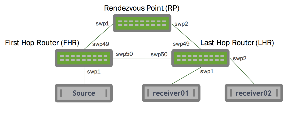
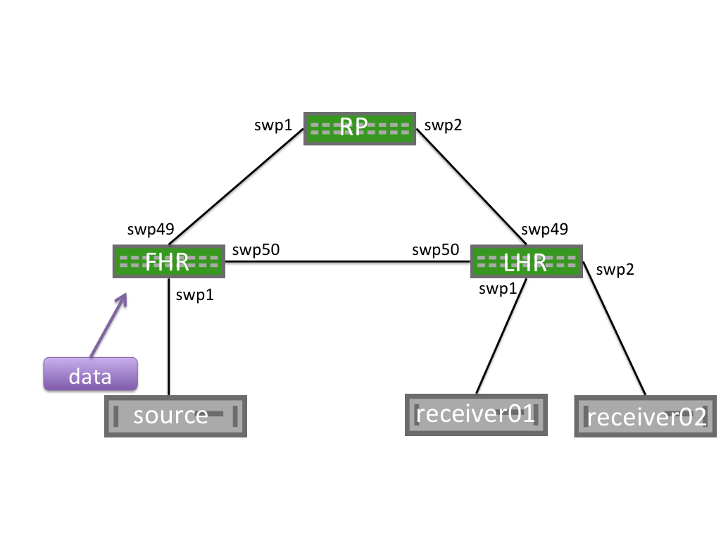
The following illustration shows a PIM configuration. The table below the illustration describes the network elements.
Network Element | Description |
|---|---|
| First Hop Router (FHR) | The router attached to the source. The FHR is responsible for the PIM register process. |
| Last Hop Router (LHR) | The last router in the path, attached to an interested multicast receiver. There is a single LHR for each network subnet with an interested receiver, however multicast groups can have multiple LHRs throughout the network. |
| Rendezvous Point (RP) | Allows for the discovery of multicast sources and multicast receivers. The RP is responsible for sending PIM Register Stop messages to FHRs. The PIM RP address must be globally routable.
|
| PIM Shared Tree (RP Tree) or (*,G) Tree | The multicast tree rooted at the RP. When receivers want to join a multicast group, join messages are sent along the shared tree towards the RP. |
| PIM Shortest Path Tree (SPT) or (S,G) Tree | The multicast tree rooted at the multicast source for a given group. Each multicast source has a unique SPT. The SPT can match the RP Tree, but this is not a requirement. The SPT represents the most efficient way to send multicast traffic from a source to the interested receivers. |
| Outgoing Interface (OIF) | Indicates the interface on which a PIM or multicast packet is to be sent out. OIFs are the interfaces towards the multicast receivers. |
| Incoming Interface (IIF) | Indicates the interface on which a multicast packet is received. An IIF can be the interface towards the source or towards the RP. |
| Reverse Path Forwarding Interface (RPF Interface) | The path used to reach the RP or source. There must be a valid PIM neighbor to determine the RPF unless directly connected to source. |
| Multicast Route (mroute) | Indicates the multicast source and multicast group as well as associated OIFs, IIFs, and RPF information. |
| Star-G mroute (*,G) | Represents the RP Tree. The * is a wildcard indicating any multicast source. The G is the multicast group. An example (*,G) is (*, 239.1.2.9). |
| S-G mroute (S,G) | This is the mroute representing the source entry. The S is the multicast source IP. The G is the multicast group. An example (S,G) is (10.1.1.1, 239.1.2.9). |
PIM Messages
PIM Message |
Description |
|---|---|
| PIM Hello | Announce the presence of a multicast router on a segment. PIM hellos are sent every 30 seconds by default. For example:22.1.2.2 > 224.0.0.13 |
| PIM Join/Prune (J/P) | Indicate the groups that a multicast router wants to receive or no longer receive. Often PIM join/prune messages are described as distinct message types, but are actually a single PIM message with a list of groups to join and a second list of groups to leave. PIM J/P messages can be to join or prune from the SPT or RP trees (also called (*,G) joins or (S,G) joins). Note: PIM join/prune messages are sent to PIM neighbors on individual interfaces. Join/prune messages are never unicast. 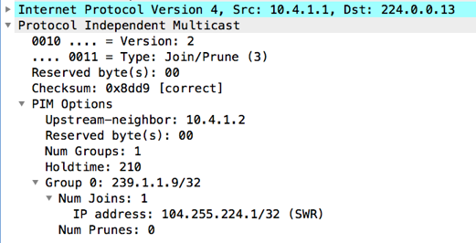 This PIM join/prune is for group 239.1.1.9, with 1 join and 0 prunes for the group. Join/prunes for multiple groups can exist in a single packet. The following shows an S,G Prune example: 21:49:59.470885 IP (tos 0x0, ttl 255, id 138, offset 0, flags [none], proto PIM (103), length 54) |
| PIM Register | Unicast packets sent from an FHR destined to the RP to advertise a multicast group. The FHR fully encapsulates the original multicast packet in PIM register messages. The RP is responsible for decapsulating the PIM register message and forwarding it along the (*,G) tree towards the receivers. |
| PIM Null Register | A special type of PIM register message where the Null-Register flag is set within the packet. Null register messages are used for an FHR to signal to an RP that a source is still sending multicast traffic. Unlike normal PIM register messages, null register messages do not encapsulate the original data packet. |
| PIM Register Stop | Sent by an RP to the FHR to indicate that PIM register messages must no longer be sent. For example:21:37:00.419379 IP (tos 0x0, ttl 255, id 24, offset 0, flags [none], proto PIM (103), length 38) |
| IGMP Membership Report (IGMP Join) | Sent by multicast receivers to tell multicast routers of their interest in a specific multicast group. IGMP join messages trigger PIM *,G joins. IGMP version 2 queries are sent to the all hosts multicast address, 224.0.0.1. IGMP version 2 reports (joins) are sent to the group’s multicast address. IGMP version 3 messages are sent to an IGMP v3 specific multicast address, 224.0.0.22. |
| IGMP Leave | Tell a multicast router that a multicast receiver no longer wants the multicast group. IGMP leave messages trigger PIM *,G prunes. |
PIM Neighbors
When PIM is configured on an interface, PIM Hello messages are sent to the link local multicast group 224.0.0.13. Any other router configured with PIM on the segment that hears the PIM Hello messages builds a PIM neighbor with the sending device.
PIM neighbors are stateless. No confirmation of neighbor relationship is exchanged between PIM endpoints.
Configure PIM
To configure PIM, run the following commands:
Configure the PIM interfaces. You must enable PIM on all interfaces facing multicast sources or multicast receivers, as well as on the interface where the RP address is configured.
cumulus@switch:~$ net add interface swp1 pimIn Cumulus Linux 4.0 the sm keyword is no longer required. In Cumulus Linux releases 3.7 and earlier, the correct command is
net add interface swp1 pim sm.Enable IGMP on all interfaces with hosts attached. IGMP version 3 is the default. Only specify the version if you exclusively want to use IGMP version 2. SSM requires the use of IGMP version 3. You must configure IGMP on all interfaces where multicast receivers exist.
cumulus@switch:~$ net add interface swp1 igmpFor ASM, configure a group mapping for a static RP:
cumulus@switch:~$ net add pim rp 192.168.0.1
cumulus@switch:~$ net pending
cumulus@switch:~$ net commit
Each PIM enabled device must configure a static RP to a group mapping and all PIM-SM enabled devices must have the same RP to group mapping configuration.
IP PIM RP group ranges can overlap. Cumulus Linux performs a longest prefix match (LPM) to determine the RP. In the following example, if the group is in 224.10.2.5, RP 192.168.0.2 is selected. If the group is in 224.10.15, RP 192.168.0.1 is selected:
cumulus@switch:~$ net add pim rp 192.168.0.1 224.10.0.0/16
cumulus@switch:~$ net add pim rp 192.168.0.2 224.10.2.0/24
PIM is included in the FRRouting package. For proper PIM operation, PIM depends on Zebra. PIM also relies on unicast routing to be configured and operational for RPF operations. You must configure a routing protocol or static routes.
Edit the
/etc/frr/daemonsfile and addpimd=yesto the end of the file:cumulus@switch:~$ sudo nano /etc/frr/daemons ... pimd=yes ...Restart FRR with this command:
cumulus@switch:~$ sudo systemctl restart frr.service
Restarting FRR restarts all the routing protocol daemons that are enabled and running.
In the vtysh shell, run the following commands to configure the PIM interfaces. PIM must be enabled on all interfaces facing multicast sources or multicast receivers, as well as on the interface where the RP address is configured.
In Cumulus Linux 4.0 the sm keyword is no longer required.
cumulus@switch:~$ sudo vtysh

switch# configure terminal
switch(config)# interface swp1
switch(config-if)# ip pim
Enable IGMP on all interfaces with hosts attached. IGMP version 3 is the default. Only specify the version if you exclusively want to use IGMP version 2.
switch(config-if)# ip igmp
switch(config-if)# exit
switch(config)#
You must configure IGMP on all interfaces where multicast receivers exist.
For ASM, configure a group mapping for a static RP:
switch(config)# ip pim rp 192.168.0.1
switch(config)# exit
switch# write memory
switch#  exit
cumulus@switch:~$
Each PIM enabled device must configure a static RP to a group mapping and all PIM-SM enabled devices must have the same RP to group mapping configuration.
IP PIM RP group ranges can overlap. Cumulus Linux performs a longest prefix match (LPM) to determine the RP. In the following example, if the group is in 224.10.2.5, RP 192.168.0.2 is selected. If the group is in 224.10.15, RP 192.168.0.1 is selected:
switch(config)# ip pim rp 192.168.0.1 224.10.0.0/16
switch(config)# ip pim rp 192.168.0.2 224.10.2.0/24
PIM Sparse Mode (PIM-SM)
PIM Sparse Mode (PIM-SM) is a pull multicast distribution method; multicast traffic is only sent through the network if receivers explicitly ask for it. When a receiver pulls multicast traffic, the network must be periodically notified that the receiver wants to continue the multicast stream.
This behavior is in contrast to PIM Dense Mode (PIM-DM), where traffic is flooded, and the network must be periodically notified that the receiver wants to stop receiving the multicast stream.
PIM-SM has three configuration options:
- Any-source Mulitcast (ASM) is the traditional, and most commonly deployed PIM implementation. ASM relies on rendezvous points to connect multicast senders and receivers that then dynamically determine the shortest path through the network between source and receiver, to efficiently send multicast traffic.
- Bidirectional PIM (BiDir) forwards all traffic through the multicast rendezvous point (RP) instead of tracking multicast source IPs, allowing for greater scale while resulting in inefficient forwarding of network traffic.
- Source Specific Multicast (SSM) requires multicast receivers to know exactly from which source they want to receive multicast traffic instead of relying on multicast rendezvous points. SSM requires the use of IGMPv3 on the multicast clients.
Cumulus Linux only supports ASM and SSM. PIM BiDir is not currently supported.
For additional information, see RFC 7761 - Protocol Independent Multicast - Sparse Mode.
Any-source Multicast Routing (ASM)
Multicast routing behaves differently depending on whether the source is sending before receivers request the multicast stream, or if a receiver tries to join a stream before there are any sources.
Receiver Joins First
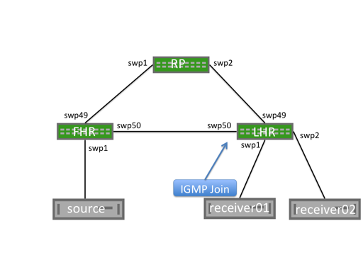
When a receiver joins a group, an IGMP membership join message is sent to the IGMPv3 multicast group, 224.0.0.22. The PIM multicast router for the segment that is listening to the IGMPv3 group receives the IGMP membership join message and becomes an LHR for this group.
This creates a (*,G) mroute with an OIF of the interface on which the IGMP Membership Report is received and an IIF of the RPF interface for the RP.
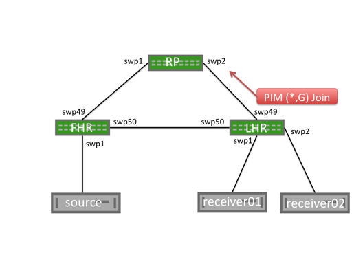
The LHR generates a PIM (*,G) join message and sends it from the interface towards the RP. Each multicast router between the LHR and the RP builds a (*,G) mroute with the OIF being the interface on which the PIM join message is received and an Incoming Interface of the reverse path forwarding interface for the RP.
When the RP receives the (*,G) Join message, it does not send any additional PIM join messages. The RP maintains a (*,G) state as long as the receiver wants to receive the multicast group.
Unlike multicast receivers, multicast sources do not send IGMP (or PIM) messages to the FHR. A multicast source begins sending, and the FHR receives the traffic and builds both a (*,G) and an (S,G) mroute. The FHR then begins the PIM register process.
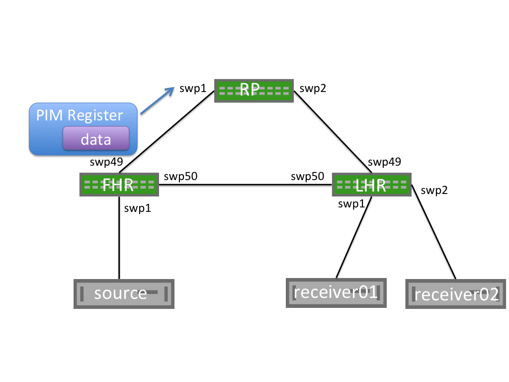
PIM Register Process
When a first hop router (FHR) receives a multicast data packet from a source, the FHR does not know if there are any interested multicast receivers in the network. The FHR encapsulates the data packet in a unicast PIM register message. This packet is sourced from the FHR and destined to the RP address. The RP builds an (S,G) mroute, decapsulates the multicast packet, and forwards it along the (*,G) tree.
As the unencapsulated multicast packet travels down the (*,G) tree towards the interested receivers, at the same time, the RP sends a PIM (S,G) join towards the FHR. This builds an (S,G) state on each multicast router between the RP and FHR.
When the FHR receives a PIM (S,G) join, it continues encapsulating and sending PIM register messages, but also makes a copy of the packet and sends it along the (S,G) mroute.
The RP then receives the multicast packet along the (S,G) tree and sends a PIM register stop to the FHR to end the register process.
 |  |
PIM SPT Switchover
When the LHR receives the first multicast packet, it sends a PIM (S,G) join towards the FHR to efficiently forward traffic through the network. This builds the shortest path tree (SPT), or the tree that is the shortest path to the source. When the traffic arrives over the SPT, a PIM (S,G) RPT prune is sent up the shared tree towards the RP. This removes multicast traffic from the shared tree; multicast data is only sent over the SPT.
You can configure SPT switchover on a per-group basis, allowing for some groups to never switch to a shortest path tree; this is also called SPT infinity. The LHR now sends both (*,G) joins and (S,G) RPT prune messages towards the RP.
To configure a group to never follow the SPT, create the necessary prefix-lists, then configure SPT switchover for the spt-range prefix-list:
cumulus@switch:~$ sudo vtysh
switch# configure terminal
switch(config)# ip prefix-list spt-range permit 235.0.0.0/8 ge 32
switch(config)# ip prefix-list spt-range permit 238.0.0.0/8 ge 32
switch(config)# ip pim spt-switchover infinity prefix-list spt-range
switch(config)# end
switch# exit
cumulus@switch:~$
To view the configured prefix-list, run the vtysh show ip mroute command or the NCLU net show mroute command. The following command shows that 235.0.0.0 is configured for SPT switchover, identified by pimreg.
switch# show ip mroute
Source          Group           Proto  Input      Output     TTL  Uptime
*               235.0.0.0       IGMP   swp31s0    pimreg     1    00:03:3
                                IGMP              br1        1    00:03:38
*               238.0.0.0       IGMP   swp31s0    br1        1    00:02:08
Sender Starts Before Receivers Join
A multicast sender can send multicast data without any additional IGMP or PIM signaling. When the FHR receives the multicast traffic, it encapsulates it and sends a PIM register to the rendezvous point (RP).
When the RP receives the PIM register, it builds an (S,G) mroute; however, there is no (*,G) mroute and no interested receivers.
The RP drops the PIM register message and immediately sends a PIM register stop message to the FHR.
Receiving a PIM register stop without any associated PIM joins leaves the FHR without any outgoing interfaces. The FHR drops this multicast traffic until a PIM join is received.
PIM register messages are sourced from the interface that receives the multicast traffic and are destined to the RP address. The PIM register is not sourced from the interface towards the RP.
PIM Null-Register
To notify the RP that multicast traffic is still flowing when the RP has no receiver, or if the RP is not on the SPT tree, the FHR periodically sends PIM null register messages. The FHR sends a PIM register with the Null-Register flag set, but without any data. This special PIM register notifies the RP that a multicast source is still sending, in case any new receivers come online.
After receiving a PIM Null-Register, the RP immediately sends a PIM register stop to acknowledge the reception of the PIM null register message.
Source Specific Multicast Mode (SSM)
The source-specific multicast method uses prefix lists to configure a receiver to only allow traffic to a multicast address from a single source. This removes the need for an RP, as the source must be known before traffic can be accepted. There is no additional PIM configuration required to enable SSM beyond enabling PIM and IGMPv3 on the relevant interfaces.
Receiver Joins First
When a receiver sends an IGMPv3 Join with the source defined the LHR builds an S,G entry and sends a PIM S,G join to the PIM neighbor closest to the source, according to the routing table.
The full path between LHR and FHR contains an S,G state, although no multicast traffic is flowing. Periodic IGMPv3 joins between the receiver and LHR, as well as PIM S,G joins between PIM neighbors, maintain this state until the receiver leaves.
When the sender begins, traffic immediately flows over the pre-built SPT from the sender to the receiver.
Sender Starts Before Receivers Join
In SSM when a sender begins sending, the FHR does not have any existing mroutes. The traffic is dropped and nothing further happens until a receiver joins. SSM does no rely on an RP; there is no PIM Register process.
Differences between Source Specific Multicast and Any Source Multicast
SSM differs from ASM multicast in the following ways:
- An RP is not configured or used. SSM does not require an RP since receivers always know the addresses of the senders.
- There is no *,G PIM Join message. The multicast sender is always known so the PIM Join messages used in SSM are always S,G Join messages.
- There is no Shared Tree or *,G tree. The PIM join message is always sent towards the source, building the SPT along the way. There is no shared tree or *,G state.
- IGMPv3 is required. ASM allows for receivers to specify only the group they want to join without knowledge of the sender. This can be done in both IGMPv2 and IGMPv3. Only IGMPv3 supports requesting a specific source for a multicast group (the sending an S,G IGMP join)
- No PIM Register process or SPT Switchover. Without a shared tree or RP, there is no need for the PIM register process. S,G joins are sent directly towards the FHR.
PIM Active-Active with MLAG
For a multicast sender or receiver to be supported over a dual-attached MLAG bond, you must configure pim active-active.
To configure PIM active-active with MLAG, run the following commands:
On the VLAN interface where multicast sources or receivers exist, configure
pim active-activeandigmp. For example:cumulus@switch:~$ net add vlan 12 pim active-active cumulus@switch:~$ net add vlan 12 igmp cumulus@switch:~$ net pending cumulus@switch:~$ net commit
Enabling PIM active-active automatically enables PIM on that interface.
Confirm PIM active-active is configured with the
net show pim mlag summarycommand:cumulus@leaf01:mgmt:~$ net show pim mlag summary MLAG daemon connection: up MLAG peer state: up Zebra peer state: up MLAG role: PRIMARY Local VTEP IP: 0.0.0.0 Anycast VTEP IP: 0.0.0.0 Peerlink: peerlink.4094 Session flaps: mlagd: 0 mlag-peer: 0 zebra-peer: 0 Message Statistics: mroute adds: rx: 5, tx: 5 mroute dels: rx: 0, tx: 0 peer zebra status updates: 1 PIM status updates: 0 VxLAN updates: 0
Configure
ip pim active-activeon the VLAN interface where the multicast source or receiver exists along with the requiredip igmpcommand.cumulus@leaf01:~$ sudo vtysh leaf01# configure terminal leaf01(config)# interface vlan12 leaf01(config-if)# ip pim active-active leaf01(config-if)# ip igmp
Enabling PIM active-active automatically enables PIM on that interface.
Confirm that PIM active-active is configured with the
show ip pim mlag summarycommand:leaf01# show ip pim mlag summary MLAG daemon connection: up MLAG peer state: up Zebra peer state: up MLAG role: PRIMARY Local VTEP IP: 0.0.0.0 Anycast VTEP IP: 0.0.0.0 Peerlink: peerlink.4094 Session flaps: mlagd: 0 mlag-peer: 0 zebra-peer: 0 Message Statistics: mroute adds: rx: 5, tx: 5 mroute dels: rx: 0, tx: 0 peer zebra status updates: 1 PIM status updates: 0 VxLAN updates: 0
Multicast Sender
When a multicast sender is attached to an MLAG bond, the sender hashes the outbound multicast traffic over a single member of the bond. Traffic is received on one of the MLAG enabled switches. Regardless of which switch receives the traffic, it is forwarded over the MLAG peer link to the other MLAG-enabled switch, because the peerlink is always considered a multicast router port and will always receive the multicast stream.
Traffic from multicast sources attached to an MLAG bond is always sent over the MLAG peerlink. Be sure to size the peerlink appropriately to accommodate this traffic.
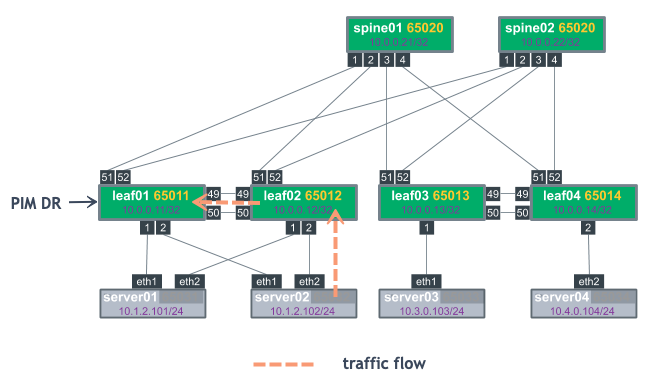
The PIM DR for the VLAN where the source resides is responsible for sending the PIM register towards the RP. The PIM DR is the PIM speaker with the highest IP address on the segment. After the PIM register process is complete and traffic is flowing along the Shortest Path Tree (SPT), either MLAG switch will forward traffic towards the receivers.
Examples are provided below that show the flow of traffic between server02 and server03:
- Step 1: server02 sends traffic to leaf02. leaf02 forwards traffic to leaf01 because the peerlink is a multicast router port. leaf01 also receives a PIM register from leaf02. leaf02 syncs the *,G table from leaf01 as an MLAG active-active peer.
- Step 2: leaf02 has the *,G route indicating that traffic is to be forwarded toward spine01. Either leaf02 or leaf01 sends this traffic directly based on which MLAG switch receives it from the attached source. In this case, leaf02 receives the traffic on the MLAG bond and forwards it directly upstream.
| Step 1 | Step 2 |
|---|---|
 | 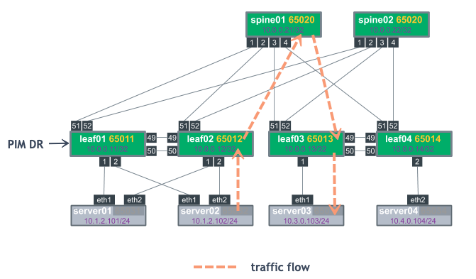 |
To show the PIM DR, run the NCLU net show pim interface command or the vtysh show ip pim interface command. The following example shows that in Vlan12 the DR is 10.1.2.12.
cumulus@leaf01:mgmt:~$ net show pim interface
Interface         State          Address  PIM Nbrs           PIM DR  FHR IfChannels
lo                   up        10.0.0.11         0            local    0          0
pimreg               up          0.0.0.0         0            local    0          0
swp51                up        10.0.0.11         1        10.0.0.21    0          4
swp52                up        10.0.0.11         1        10.0.0.22    0          0
vlan12               up        10.1.2.11         1        10.1.2.12    0          2
PIM joins sent towards the source can be ECMP load shared by upstream PIM neighbors (spine01 and spine02 in the example above). Either MLAG member can receive the PIM join and forward traffic, regardless of DR status.
Multicast Receiver
A dual-attached multicast receiver sends an IGMP join on the attached VLAN. The specific interface that is used is determined based on the host. The IGMP join is received on one of the MLAG switches, and the IGMP join is added to the IGMP Join table and layer 2 MDB table. The layer 2 MDB table, like the unicast MAC address table, is synced via MLAG control messages over the peerlink. This allows both MLAG switches to program IGMP and MDB table forwarding information.
Both switches send *,G PIM Join messages towards the RP. If the source is already sending, both MLAG switches receive the multicast stream.
Traditionally, the PIM DR is the only node to send the PIM *,G Join, but to provide resiliency in case of failure, both MLAG switches send PIM *,G Joins towards the RP to receive the multicast stream.
To prevent duplicate multicast packets, a Designated Forward (DF) is elected. The DF is the primary member of the MLAG pair. As a result, the MLAG secondary does not put the VLAN in the Outgoing Interface List (OIL), preventing duplicate multicast traffic.
Verify PIM
The following outputs are based on the Cumulus Reference Topology with cldemo-pim.
Source Starts First
On the FHR, an mroute is built, but the upstream state is Prune. The FHR flag is set on the interface receiving multicast. Run the NCLU net show commands to review detailed output for the FHR. For example:
cumulus@fhr:~$ net show mroute
Source          Group           Proto  Input      Output     TTL  Uptime
172.16.5.105    239.1.1.1       none   br0        none       0    --:--:--
!
cumulus@fhr:~$ net show pim upstream
Iif Source Group State Uptime JoinTimer RSTimer KATimer RefCnt
br0 172.16.5.105 239.1.1.1 Prune 00:07:40 --:--:-- 00:00:36 00:02:50 1
!
cumulus@fhr:~$ net show pim upstream-join-desired
Interface Source          Group           LostAssert Joins PimInclude JoinDesired EvalJD
!
cumulus@fhr:~$ net show pim interface
Interface  State          Address  PIM Nbrs           PIM DR  FHR
br0           up       172.16.5.1         0            local    1
swp51         up        10.1.0.17         1            local    0
swp52         up        10.1.0.19         0            local    0
!
cumulus@fhr:~$ net show pim state
Source           Group            IIF    OIL
172.16.5.105     239.1.1.1        br0
!
cumulus@fhr:~$ net show pim interface detail
Interface : br0
State     : up
Address   : 172.16.5.1
Designated Router
-----------------
Address   : 172.16.5.1
Priority  : 1
Uptime    : --:--:--
Elections : 2
Changes   : 0

FHR - First Hop Router
----------------------
239.1.1.1 : 172.16.5.105 is a source, uptime is 00:27:43
On the RP, no mroute state is created, but the net show pim upstream output includes the Source and Group:
cumulus@rp01:~$ net show mroute
Source          Group           Proto  Input      Output     TTL  Uptime
!
cumulus@rp01:~$ net show pim upstream
Iif       Source          Group           State       Uptime   JoinTimer RSTimer   KATimer   RefCnt
swp30     172.16.5.105    239.1.1.1       Prune       00:00:19 --:--:--  --:--:--  00:02:46       1
As a receiver joins the group, the mroute output interface on the FHR transitions from none to the RPF interface of the RP:
cumulus@fhr:~$ net show mroute
Source          Group           Proto  Input      Output     TTL  Uptime
172.16.5.105    239.1.1.1       PIM    br0        swp51      1    00:05:40
!
cumulus@fhr:~$ net show pim upstream
Iif       Source          Group           State       Uptime   JoinTimer RSTimer   KATimer   RefCnt
br0       172.16.5.105    239.1.1.1       Prune       00:48:23 --:--:--  00:00:00  00:00:37       2
!

cumulus@fhr:~$ net show pim upstream-join-desired
Interface Source          Group           LostAssert Joins PimInclude JoinDesired EvalJD
swp51     172.16.5.105    239.1.1.1       no         yes   no         yes         yes
!
cumulus@fhr:~$ net show pim state
Source           Group            IIF    OIL
172.16.5.105     239.1.1.1        br0    swp51

cumulus@rp01:~$ net show mroute
Source          Group           Proto  Input      Output     TTL  Uptime
*               239.1.1.1       PIM    lo         swp1       1    00:09:59
172.16.5.105    239.1.1.1       PIM    swp30      swp1       1    00:09:59
!
cumulus@rp01:~$ net show pim upstream
Iif       Source          Group           State       Uptime   JoinTimer RSTimer   KATimer   RefCnt
lo        *               239.1.1.1       Joined      00:10:01 00:00:59  --:--:--  --:--:--       1
swp30     172.16.5.105    239.1.1.1       Joined      00:00:01 00:00:59  --:--:--  00:02:35       1
!
cumulus@rp01:~$ net show pim upstream-join-desired
Interface Source          Group           LostAssert Joins PimInclude JoinDesired EvalJD
swp1      *               239.1.1.1       no         yes   no         yes         yes
!
cumulus@rp01:~$ net show pim state
Source           Group            IIF    OIL
*                239.1.1.1        lo     swp1
172.16.5.105     239.1.1.1        swp30  swp1
Receiver Joins First
On the LHR attached to the receiver:
cumulus@lhr:~$ net show mroute
Source          Group           Proto  Input      Output     TTL  Uptime
*               239.2.2.2       IGMP   swp51      br0        1    00:01:19
!
cumulus@lhr:~$ net show pim local-membership
Interface Address         Source          Group           Membership
br0       172.16.1.1      *               239.2.2.2       INCLUDE
!
cumulus@lhr:~$ net show pim state
Source           Group            IIF    OIL
*                239.2.2.2        swp51  br0
!
cumulus@lhr:~$ net show pim upstream
Iif       Source          Group           State       Uptime   JoinTimer RSTimer   KATimer   RefCnt
swp51     *               239.2.2.2       Joined      00:02:07 00:00:53  --:--:--  --:--:--       1
!
cumulus@lhr:~$ net show pim upstream-join-desired
Interface Source          Group           LostAssert Joins PimInclude JoinDesired EvalJD
br0       *               239.2.2.2       no         no    yes        yes         yes
!
cumulus@lhr:~$ net show igmp groups
Interface Address         Group           Mode Timer    Srcs V Uptime
br0       172.16.1.1      239.2.2.2       EXCL 00:04:02    1 3 00:04:12
!
cumulus@lhr:~$ net show igmp sources
Interface Address         Group           Source          Timer Fwd Uptime
br0       172.16.1.1      239.2.2.2       *               03:54   Y 00:04:21
On the RP
cumulus@rp01:~$ net show mroute
Source          Group           Proto  Input      Output     TTL  Uptime
*               239.2.2.2       PIM    lo         swp1       1    00:00:03
!
cumulus@rp01:~$ net show pim state
Source           Group            IIF    OIL
*                239.2.2.2        lo     swp1
!
cumulus@rp01:~$ net show pim upstream
Iif       Source          Group           State       Uptime   JoinTimer RSTimer   KATimer   RefCnt
lo        *               239.2.2.2       Joined      00:05:17 00:00:43  --:--:--  --:--:--       1
!
cumulus@rp01:~$ net show pim upstream-join-desired
Interface Source          Group           LostAssert Joins PimInclude JoinDesired EvalJD
swp1      *               239.2.2.2       no         yes   no         yes         yes
Source Starts First
On the FHR, an mroute is built, but the upstream state is Prune. The FHR flag is set on the interface receiving multicast.
Use the vtysh show ip commands to review detailed output for the FHR. For example:
cumulus@fhr:~$ sudo vtysh
fhr# show ip mroute
Source          Group           Proto  Input      Output     TTL  Uptime
172.16.5.105    239.1.1.1       none   br0        none       0    --:--:--

fhr# show ip pim upstream
Iif Source Group State Uptime JoinTimer RSTimer KATimer RefCnt
br0 172.16.5.105 239.1.1.1 Prune 00:07:40 --:--:-- 00:00:36 00:02:50 1

fhr# show ip pim upstream-join-desired
Interface Source          Group           LostAssert Joins PimInclude JoinDesired EvalJD
!
fhr# show ip pim interface
Interface  State          Address  PIM Nbrs           PIM DR  FHR
br0           up       172.16.5.1         0            local    1
swp51         up        10.1.0.17         1            local    0
swp52         up        10.1.0.19         0            local    0

fhr# show ip pim state
Source           Group            IIF    OIL
172.16.5.105     239.1.1.1        br0

fhr# show ip pim interface detail
Interface : br0
State     : up
Address   : 172.16.5.1
Designated Router
-----------------
Address   : 172.16.5.1
Priority  : 1
Uptime    : --:--:--
Elections : 2
Changes   : 0

FHR - First Hop Router
----------------------
239.1.1.1 : 172.16.5.105 is a source, uptime is 00:27:43
On the RP, no mroute state is created, but the show ip pim upstream output includes the Source and Group:
rp01# show ip mroute
Source          Group           Proto  Input      Output     TTL  Uptime

rp01# show ip pim upstream
Iif       Source          Group           State       Uptime   JoinTimer RSTimer   KATimer   RefCnt
swp30     172.16.5.105    239.1.1.1       Prune       00:00:19 --:--:--  --:--:--  00:02:46       1
As a receiver joins the group, the mroute output interface on the FHR transitions from none to the RPF interface of the RP:
fhr# show ip mroute
Source          Group           Proto  Input      Output     TTL  Uptime
172.16.5.105    239.1.1.1       PIM    br0        swp51      1    00:05:40

fhr# show ip pim upstream
Iif       Source          Group           State       Uptime   JoinTimer RSTimer   KATimer   RefCnt
br0       172.16.5.105    239.1.1.1       Prune       00:48:23 --:--:--  00:00:00  00:00:37       2

fhr# show ip pim upstream-join-desired
Interface Source          Group           LostAssert Joins PimInclude JoinDesired EvalJD
swp51     172.16.5.105    239.1.1.1       no         yes   no         yes         yes

fhr# show ip pim state
Source           Group            IIF    OIL
172.16.5.105     239.1.1.1        br0    swp51

rp01# show ip mroute
Source          Group           Proto  Input      Output     TTL  Uptime
*               239.1.1.1       PIM    lo         swp1       1    00:09:59
172.16.5.105    239.1.1.1       PIM    swp30      swp1       1    00:09:59

rp01# show ip pim upstream
Iif       Source          Group           State       Uptime   JoinTimer RSTimer   KATimer   RefCnt
lo        *               239.1.1.1       Joined      00:10:01 00:00:59  --:--:--  --:--:--       1
swp30     172.16.5.105    239.1.1.1       Joined      00:00:01 00:00:59  --:--:--  00:02:35       1

rp01# show ip pim upstream-join-desired
Interface Source          Group           LostAssert Joins PimInclude JoinDesired EvalJD
swp1      *               239.1.1.1       no         yes   no         yes         yes

rp01# show ip pim state
Source           Group            IIF    OIL
*                239.1.1.1        lo     swp1
172.16.5.105     239.1.1.1        swp30  swp1
Receiver Joins First
On the LHR attached to the receiver:
lhr# show ip mroute
Source          Group           Proto  Input      Output     TTL  Uptime
*               239.2.2.2       IGMP   swp51      br0        1    00:01:19

lhr# show ip pim local-membership
Interface Address         Source          Group           Membership
br0       172.16.1.1      *               239.2.2.2       INCLUDE

lhr# show ip pim state
Source           Group            IIF    OIL
    *                239.2.2.2        swp51  br0

lhr# show ip pim upstream
Iif       Source          Group           State       Uptime   JoinTimer RSTimer   KATimer   RefCnt
swp51     *               239.2.2.2       Joined      00:02:07 00:00:53  --:--:--  --:--:--       1

lhr# show ip pim upstream-join-desired
Interface Source          Group           LostAssert Joins PimInclude JoinDesired EvalJD
br0       *               239.2.2.2       no         no    yes        yes         yes

lhr# show ip igmp groups
Interface Address         Group           Mode Timer    Srcs V Uptime
    br0       172.16.1.1      239.2.2.2       EXCL 00:04:02    1 3 00:04:12

lhr# show ip igmp sources
Interface Address         Group           Source          Timer Fwd Uptime
br0       172.16.1.1      239.2.2.2       *               03:54   Y 00:04:21
On the RP:
rp01# show ip mroute
Source          Group           Proto  Input      Output     TTL  Uptime
*               239.2.2.2       PIM    lo         swp1       1    00:00:03

rp01# show ip pim state
    Source           Group            IIF    OIL
    *                239.2.2.2        lo     swp1

rp01# show ip pim upstream
Iif       Source          Group           State       Uptime   JoinTimer RSTimer   KATimer   RefCnt
lo        *               239.2.2.2       Joined      00:05:17 00:00:43  --:--:--  --:--:--       1
rp01# show ip pim upstream-join-desired
Interface Source          Group           LostAssert Joins PimInclude JoinDesired EvalJD
swp1      *               239.2.2.2       no         yes   no         yes         yes
Additional PIM Features
Custom SSM multicast group ranges
PIM considers 232.0.0.0/8 the default SSM range. You can change the SSM range by defining a prefix-list and attaching it to the ssm-range command. You can change the default SSM group or add additional group ranges to be treated as SSM groups.
If you use the ssm-range command, all SSM ranges must be in the prefix-list, including 232.0.0.0/8.
Create a prefix-list with the permit keyword to match address ranges that should be treated as SSM groups and deny keyword for those ranges which should not be treated as SSM enabled ranges.
cumulus@switch:~$ net add routing prefix-list ipv4 my-custom-ssm-range seq 5 permit 232.0.0.0/8 ge 32
cumulus@switch:~$ net add routing prefix-list ipv4 my-custom-ssm-range seq 10 permit 238.0.0.0/8 ge 32
Apply the custom prefix-list as an ssm-range
cumulus@switch:~$ net add pim ssm prefix-list my-custom-ssm-range
cumulus@switch:~$ net pending
cumulus@switch:~$ net commit
To view the configured prefix-lists, run the net show ip prefix-list command:
cumulus@switch:~$ net show ip prefix-list my-custom-ssm-range
ZEBRA: ip prefix-list my-custom-ssm-range: 1 entries
   seq 5 permit 232.0.0.0/8 ge 32
PIM: ip prefix-list my-custom-ssm-range: 1 entries
   seq 10 permit 232.0.0.0/8 ge 32
Create a prefix-list with the permit keyword to match address ranges that you want to treat as SSM groups and the deny keyword for the ranges you do not want to treat as SSM-enabled ranges:
cumulus@switch:~$ sudo vtysh
switch# configure terminal
switch(config)# ip prefix-list ssm-range seq 5 permit 232.0.0.0/8 ge 32
switch(config)# ip prefix-list ssm-range seq 10 permit 238.0.0.0/8 ge 32
Apply the custom prefix-list as an ssm-range:
switch(config)# ip pim ssm prefix-list ssm-range
switch(config)# exit
switch# write memory
switch# exit
cumulus@switch:~$
To view the configured prefix-lists, run the show ip prefix-list my-custom-ssm-range command:
switch#  show ip prefix-list my-custom-ssm-range
ZEBRA: ip prefix-list my-custom-ssm-range: 1 entries
   seq 5 permit 232.0.0.0/8 ge 32
PIM: ip prefix-list my-custom-ssm-range: 1 entries
   seq 10 permit 232.0.0.0/8 ge 32
PIM and ECMP
PIM uses the RPF procedure to choose an upstream interface to build a forwarding state. If you configure equal-cost multipaths (ECMP), PIM chooses the RPF based on the ECMP hash algorithm.
Run the net add pim ecmp command to enable PIM to use all the available nexthops for the installation of mroutes. For example, if you have four-way ECMP, PIM spreads the S,G and *,G mroutes across the four different paths.
cumulus@switch:~$ net add pim ecmp
cumulus@switch:~$ net pending
cumulus@switch:~$ net commit
Run the ip pim ecmp rebalance command to recalculate all stream paths in the event of a loss of path over one of the ECMP paths. Without this command, only the streams that are using the path that is lost are moved to alternate ECMP paths. Rebalance does not affect existing groups.
cumulus@switch:~$ net add pim ecmp rebalance
cumulus@switch:~$ net pending
cumulus@switch:~$ net commit
The rebalance command might cause some packet loss.
Run the ip pim ecmp command to enable PIM to use all the available nexthops for the installation of mroutes. For example, if you have four-way ECMP, PIM spreads the S,G and *,G mroutes across the four different paths.
cumulus@switch:~$ sudo vtysh
switch# configure terminal
switch(config)# ip pim ecmp
switch(config)# exit
switch# write memory
switch# exit
cumulus@switch:~$
Run the ip pim ecmp rebalance command to recalculate all stream paths in the event of a loss of path over one of the ECMP paths. Without this command, only the streams that are using the path that is lost are moved to alternate ECMP paths. Rebalance does not affect existing groups.
cumulus@switch:~$ sudo vtysh

switch# configure terminal
switch(config)# ip pim ecmp rebalance
switch(config)# exit
switch# write memory
switch# exit
cumulus@switch:~$
The rebalance command might cause some packet loss.
To show which nexthop is selected for a specific source/group, run the show ip pim nexthop command from the vtysh shell:
cumulus@switch:~$ sudo vtysh
switch# show ip pim nexthop
Number of registered addresses: 3
Address         Interface      Nexthop
-------------------------------------------
6.0.0.9         swp31s0        169.254.0.9
6.0.0.9         swp31s1        169.254.0.25
6.0.0.11        lo             0.0.0.0
6.0.0.10        swp31s0        169.254.0.9
6.0.0.10        swp31s1        169.254.0.25
IP Multicast Boundaries
Multicast boundaries enable you to limit the distribution of multicast traffic by setting boundaries with the goal of pushing multicast to a subset of the network.
With such boundaries in place, any incoming IGMP or PIM joins are dropped or accepted based upon the prefix-list specified. The boundary is implemented by applying an IP multicast boundary OIL (outgoing interface list) on an interface.
To configure the boundary, first create a prefix-list as described above, then run the following commands to configure the IP multicast boundary:
cumulus@switch:~$ net add interface swp1 multicast boundary oil <prefix-list>
cumulus@switch:~$ net pending
cumulus@switch:~$ net commit
cumulus@switch:~$ sudo vtysh
switch# configure terminal
switch(config)# interface swp1
switch(config-if)# ip multicast boundary oil <prefix-list>
switch(config-if)# end
switch# write memory
switch# exit
cumulus@switch:~$
Multicast Source Discovery Protocol (MSDP)
You can use the Multicast Source Discovery Protocol (MSDP) to connect multiple PIM-SM multicast domains together, using the PIM-SM RPs. By configuring any cast RPs with the same IP address on multiple multicast switches (primarily on the loopback interface), the PIM-SM limitation of only one RP per multicast group is relaxed. This allows for an increase in both failover and load-balancing throughout.
When an RP discovers a new source (typically a PIM-SM register message), a source-active (SA) message is sent to each MSDP peer. The peer then determines if any receivers are interested.
Cumulus Linux MSDP support is primarily for anycast-RP configuration, rather than multiple multicast domains. You must configure each MSDP peer in a full mesh, as SA messages are not received and reforwarded.
Cumulus Linux currently only supports one MSDP mesh group.
The following steps demonstrate how to configure a Cumulus switch to use the MSDP:
Add an anycast IP address to the loopback interface for each RP in the domain:
cumulus@rp01:~$ net add loopback lo ip address 10.1.1.1/32
cumulus@rp01:~$ net add loopback lo ip address 10.1.1.100/32
On every multicast switch, configure the group to RP mapping using the anycast address:
cumulus@switch:$ net add pim rp 10.1.1.100 224.0.0.0/4
cumulus@switch:$ net pending
cumulus@switch:$ net commit
Configure the MSDP mesh group for all active RPs (the following example uses 3 RPs). The mesh group must include all RPs in the domain as members, with a unique address as the source. This configuration results in MSDP peerings between all RPs.
cumulus@rp01:$ net add msdp mesh-group cumulus member 100.1.1.2
cumulus@rp01:$ net add msdp mesh-group cumulus member 100.1.1.3

cumulus@rp02:$ net add msdp mesh-group cumulus member 100.1.1.1
cumulus@rp02:$ net add msdp mesh-group cumulus member 100.1.1.3

cumulus@rp03:$ net add msdp mesh-group cumulus member 100.1.1.1
cumulus@rp03:$ net add msdp mesh-group cumulus member 100.1.1.2
Pick the local loopback address as the source of the MSDP control packets:
cumulus@rp01:$ net add msdp mesh-group cumulus source 100.1.1.1

cumulus@rp02:$ net add msdp mesh-group cumulus source 100.1.1.2

cumulus@rp03:$ net add msdp mesh-group cumulus source 100.1.1.3
Inject the anycast IP address into the IGP of the domain. If the network is unnumbered and uses unnumbered BGP as the IGP, avoid using the anycast IP address for establishing unicast or multicast peerings. For PIM-SM, ensure that the unique address is used as the PIM hello source by setting the source:
cumulus@rp01:$ net add loopback lo pim use-source 100.1.1.1
cumulus@rp01:$ net pending
cumulus@rp01:$ net commit
Edit the
/etc/network/interfacesfile to add an anycast IP address to the loopback interface for each RP in the domain. For example:cumulus@rp01:~$ sudo nano /etc/network/interfaces auto lo iface lo inet loopback address 10.0.0.11/32 address 10.1.1.1/32 ...Run the
ifreload -acommand to load the new configuration:cumulus@switch:~$ ifreload -aOn every multicast switch, configure the group to RP mapping using the anycast address:
cumulus@rp01:~$ sudo vtysh

rp01# configure terminal
rp01(config)# ip pim rp 10.1.1.100 224.0.0.0/4
Configure the MSDP mesh group for all active RPs (the following example uses 3 RPs). The mesh group must include all RPs in the domain as members, with a unique address as the source. This configuration results in MSDP peerings between all RPs.
rp01(config)# ip msdp mesh-group cumulus member 100.1.1.2
rp01(config)# ip msdp mesh-group cumulus member 100.1.1.3

rp02(config)# ip msdp mesh-group cumulus member 100.1.1.1
rp02(config)# ip msdp mesh-group cumulus member 100.1.1.3

rp03(config)# ip msdp mesh-group cumulus member 100.1.1.1
rp03(config)# ip msdp mesh-group cumulus member 100.1.1.2
Pick the local loopback address as the source of the MSDP control packets
rp01# ip msdp mesh-group cumulus source 100.1.1.1
rp02# ip msdp mesh-group cumulus source 100.1.1.2
rp03# ip msdp mesh-group cumulus source 100.1.1.3
Inject the anycast IP address into the IGP of the domain. If the network is unnumbered and uses unnumbered BGP as the IGP, avoid using the anycast IP address for establishing unicast or multicast peerings. For PIM-SM, ensure that the unique address is used as the PIM hello source by setting the source:
rp01# interface lo
rp01(config-if)# ip pim use-source 100.1.1.1
rp01(config-if)# end
rp01# write memory
rp01# exit
cumulus@rp01:~$
PIM in a VRF
VRFs divide the routing table on a per-tenant basis, ultimately providing for separate layer 3 networks over a single layer 3 infrastructure. With a VRF, each tenant has its own virtualized layer 3 network, so IP addresses can overlap between tenants.
PIM in a VRF enables PIM trees and multicast data traffic to run inside a layer 3 virtualized network, with a separate tree per domain or tenant. Each VRF has its own multicast tree with its own RP(s), sources, and so on. Therefore, you can have one tenant per corporate division, client, or product; for example.
VRFs on different switches typically connect or are peered over subinterfaces, where each subinterface is in its own VRF, provided MP-BGP VPN is not enabled or supported.
To configure PIM in a VRF, run the following commands.
First, add the VRFs and associate them with switch ports:
cumulus@switch:~$ net add vrf blue
cumulus@switch:~$ net add vrf purple
cumulus@switch:~$ net add interface swp1 vrf blue
cumulus@switch:~$ net add interface swp2 vrf purple
Then add the PIM configuration to FRR, review and commit the changes:
cumulus@switch:~$ net add interface swp1 pim sm
cumulus@switch:~$ net add interface swp2 pim sm
cumulus@switch:~$ net add bgp vrf blue auto 65001
cumulus@switch:~$ net add bgp vrf purple auto 65000
cumulus@switch:~$ net add bgp vrf blue router-id 10.1.1.1
cumulus@switch:~$ net add bgp vrf purple router-id 10.1.1.2
cumulus@switch:~$ net add bgp vrf blue neighbor swp1 interface remote-as external
cumulus@switch:~$ net add bgp vrf purple neighbor swp2 interface remote-as external
cumulus@switch:~$ net pending
cumulus@switch:~$ net commit
First, edit the /etc/network/interfaces file and to the VRFs and associate them with switch ports, then run ifreload -a to reload the configuration.
cumulus@switch:~$ sudo nano /etc/network/interfaces
...
auto swp1
iface swp1
    vrf blue

auto swp2
iface swp2
    vrf purple

auto blue
iface blue
    vrf-table auto

auto purple
iface purple
    vrf-table auto
...
Then add the PIM configuration to FRR. You can do this in vtysh:
cumulus@switch:~$ sudo vtysh

switch# configure terminal
switch(config)# interface swp1
switch(config-if)# ip pim sm
switch(config-if)# exit
switch(config)# interface swp2
switch(config-if)# ip pim sm
switch(config-if)# exit
switch(config)# router bgp 65001 vrf blue
switch(config-router)# bgp router-id 10.1.1.2
switch(config-router)# neighbor swp1 interface remote-as external
switch(config-router)# exit
switch(config)# router bgp 65000 vrf purple
switch(config-router)# bgp router-id 10.1.1.1
switch(config-router)# neighbor swp2 interface remote-as external
switch(config-router)# end
switch# write memory
switch# exit
cumulus@switch:~$
To show VRF information, run the NCLU net show mroute vrf <vrf-name> command or the vtysh show ip mroute vrf <vrf-name> command:
cumulus@fhr:~$ net show mroute vrf blue
Source          Group           Proto  Input      Output     TTL  Uptime
11.1.0.1        239.1.1.1       IGMP   swp32s0    swp32s1    1    00:01:13
                                IGMP              br0.200    1    00:01:13
*               239.1.1.2       IGMP   mars       pimreg1001 1    00:01:13
                                IGMP              swp32s1    1    00:01:12
                                IGMP              br0.200    1    00:01:13
BFD for PIM Neighbors
You can use bidirectional forward detection (BFD) for PIM neighbors to quickly detect link failures. When you configure an interface, include the pim bfd option. For example:
cumulus@switch:~$ net add interface swp31s3 pim bfd
cumulus@switch:~$ net pending
cumulus@switch:~$ net commit
cumulus@switch:~$ sudo vtysh

switch# configure terminal
switch(config)# interface swp31s3
switch(config-if)# ip pim bfd
switch(config-if)# end
switch# write memory
switch# exit
cumulus@switch:~$
Troubleshooting
FHR Stuck in Registering Process
When a multicast source starts, the FHR sends unicast PIM register messages from the RPF interface towards the source. After the PIM register is received by the RP, a PIM register stop message is sent from the RP to the FHR to end the register process. If an issue occurs with this communication, the FHR becomes stuck in the registering process, which can result in high CPU, as PIM register packets are generated by the FHR CPU and sent to the RP CPU.
To assess this issue:
Review the FHR. The output interface of pimreg can be seen here. If this does not change to an interface within a few seconds, the FHR is likely stuck.
cumulus@fhr:~$ net show mroute
Source          Group           Proto  Input      Output     TTL  Uptime
172.16.5.105    239.2.2.3       PIM    br0        pimreg     1    00:03:59
To troubleshoot the issue:
Validate that the FHR can reach the RP. If the RP and FHR can not communicate, the registration process fails:
cumulus@fhr:~$ ping 10.0.0.21 -I br0
PING 10.0.0.21 (10.0.0.21) from 172.16.5.1 br0: 56(84) bytes of data.
^C
--- 10.0.0.21 ping statistics ---
4 packets transmitted, 0 received, 100% packet loss, time 3000ms
On the RP, use
tcpdumpto see if the PIM register packets are arriving:cumulus@rp01:~$ sudo tcpdump -i swp30 tcpdump: verbose output suppressed, use -v or -vv for full protocol decode listening on swp30, link-type EN10MB (Ethernet), capture size 262144 bytes 23:33:17.524982 IP 172.16.5.1 > 10.0.0.21: PIMv2, Register, length 66If PIM registration packets are being received, verify that they are seen by PIM by issuing
debug pim packetsfrom within FRRouting:cumulus@fhr:~$ sudo vtysh -c "debug pim packets" PIM Packet debugging is on cumulus@rp01:~$ sudo tail /var/log/frr/frr.log 2016/10/19 23:46:51 PIM: Recv PIM REGISTER packet from 172.16.5.1 to 10.0.0.21 on swp30: ttl=255 pim_version=2 pim_msg_size=64 checksum=a681Repeat the process on the FHR to see if PIM register stop messages are being received on the FHR and passed to the PIM process:
cumulus@fhr:~$ sudo tcpdump -i swp51
23:58:59.841625 IP 172.16.5.1 > 10.0.0.21: PIMv2, Register, length 28
23:58:59.842466 IP 10.0.0.21 > 172.16.5.1: PIMv2, Register Stop, length 18

cumulus@fhr:~$ sudo vtysh -c "debug pim packets"
PIM Packet debugging is on

cumulus@fhr:~$ sudo tail -f /var/log/frr/frr.log
2016/10/19 23:59:38 PIM: Recv PIM REGSTOP packet from 10.0.0.21 to 172.16.5.1 on swp51: ttl=255 pim_version=2 pim_msg_size=18 checksum=5a39
No *,G Is Built on LHR
The most common reason for a *,G to not be built on an LHR is for if both PIM and IGMP are not enabled on an interface facing a receiver.
lhr# show run
!
interface br0
 ip igmp
 ip ospf area 0.0.0.0
 ip pim sm
To troubleshoot this issue, if both PIM and IGMP are enabled, ensure that IGMPv3 joins are being sent by the receiver:
cumulus@lhr:~$ sudo tcpdump -i br0 igmp
tcpdump: verbose output suppressed, use -v or -vv for full protocol decode
listening on br0, link-type EN10MB (Ethernet), capture size 262144 bytes
00:03:55.789744 IP 172.16.1.101 > igmp.mcast.net: igmp v3 report, 1 group record(s)
No mroute Created on FHR
To troubleshoot this issue:
Verify that multicast traffic is being received:
cumulus@fhr:~$ sudo tcpdump -i br0
tcpdump: verbose output suppressed, use -v or -vv for full protocol decode
listening on br0, link-type EN10MB (Ethernet), capture size 262144 bytes
00:11:52.944745 IP 172.16.5.105.51570 > 239.2.2.9.1000: UDP, length 9
Verify that PIM is configured on the interface facing the source:
fhr# show run
!
interface br0
ip ospf area 0.0.0.0
ip pim sm
If PIM is configured, verify that the RPF interface for the source matches the interface on which the multicast traffic is received:
fhr# show ip rpf 172.16.5.105
Routing entry for 172.16.5.0/24 using Multicast RIB
Known via "connected", distance 0, metric 0, best
* directly connected, br0
Verify that an RP is configured for the multicast group:
fhr# show ip pim rp-info
RP address       group/prefix-list   OIF         I am RP
10.0.0.21        224.0.0.0/4         swp51       no
No S,G on RP for an Active Group
An RP does not build an mroute when there are no active receivers for a multicast group, even though the mroute was created on the FHR.
cumulus@rp01:~$ net show mroute
Source          Group           Proto  Input      Output     TTL  Uptime
spine01#

cumulus@rp01:~$ net show mroute
Source          Group           Proto  Input      Output     TTL  Uptime
172.16.5.105    239.2.2.9       none   br0        none       0    --:--:--
This is expected behavior. You can see the active source on the RP with either the NCLU net show pim upstream command or the vtysh show ip pim upstream command:
cumulus@rp01:~$ net show pim upstream
Iif       Source          Group           State       Uptime   JoinTimer RSTimer   KATimer   RefCnt
swp30     172.16.5.105    239.2.2.9       Prune       00:08:03 --:--:--  --:--:--  00:02:20       1
No mroute Entry Present in Hardware
Use the cl-resource-query command to verify that the hardware IP multicast entry is the maximum value:
cumulus@switch:~$ cl-resource-query  | grep Mcast
  Total Mcast Routes:         450,   0% of maximum value    450
For Spectrum chipsets, refer to TCAM Resource Profiles for Spectrum Switches.
Verify MSDP Session State
To verify the state of MSDP sessions, run either the NCLU net show msdp mesh-group command or the vtysh show ip msdp mesh-group command:
cumulus@switch:~$ net show msdp mesh-group
Mesh group : pod1
  Source : 100.1.1.1
  Member                 State
  100.1.1.2        established
  100.1.1.3        established
cumulus@switch:~$
cumulus@switch:~$ net show msdp peer
Peer                       Local        State    Uptime   SaCnt
100.1.1.2              100.1.1.1  established  00:07:21       0
100.1.1.3              100.1.1.1  established  00:07:21       0
View the Active Sources
To review the active sources learned locally (through PIM registers) and from MSDP peers, run either the NCLU net show msdp sa command or the vtysh show ip msdp sa command:
cumulus@switch:~$ net show msdp sa
Source                     Group               RP  Local  SPT    Uptime
44.1.11.2              239.1.1.1        100.1.1.1      n    n  00:00:40
44.1.11.2              239.1.1.2        100.1.1.1      n    n  00:00:25
Example Configurations
Caveats and Errata
- Cumulus Linux only supports PIM sparse mode (PIM-SM), any-source multicast (PIM-SM ASM), and source-specific multicast (SSM). Dense mode and bidirectional multicast are not supported.
- Non-native forwarding (register decapsulation) is not supported. Initial packet loss is expected while the PIM *,G tree is built from the rendezvous point to the FHR to trigger native forwarding.
- Cumulus Linux does not currently build an S,G mroute when forwarding over an *,G tree.