Data Center Host to ToR Architecture
This chapter discusses the various architectures and strategies available from the top of rack (ToR) switches all the way down to the server hosts.
Layer 2 - Traditional Spanning Tree - Single Attached
Example | Summary |
|---|---|
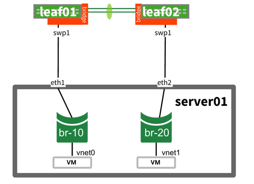 | Bond and Etherchannel are not configured on host to multiple switches (bonds can still occur but only to one switch at a time), so leaf01 and leaf02 see two different MAC addresses. |
Benefits | Considerations |
|---|---|
|
|
Active-Active Mode | Active-Passive Mode | L2 to L3 Demarcation |
|---|---|---|
| None (not possible with traditional spanning tree) | VRR |
You can configure VRR on a pair of switches at any level in the network. However, the higher up the network, the larger the layer 2 domain becomes. The benefit is layer 2 reachability. The drawback is that the layer 2 domain is more difficult to troubleshoot, does not scale as well, and the pair of switches running VRR needs to carry the entire MAC address table of everything below it in the network. Cumulus Professional Services recommends minimizing the layer 2 domain as much as possible. For more information, see this presentation. |
Example Configuration
auto bridge
iface bridge
  bridge-vlan-aware yes
  bridge-ports swp1 peerlink
  bridge-vids 1-2000
  bridge-stp on

auto bridge.10
iface bridge.10
  address 10.1.10.2/24

auto peerlink
iface peerlink
    bond-slaves glob swp49-50

auto swp1
iface swp1
  mstpctl-portadminedge yes
  mstpctl-bpduguard yes
auto eth1
iface eth1 inet manual

auto eth1.10
iface eth1.10 inet manual

auto eth2
iface eth1 inet manual

auto eth2.20
iface eth2.20 inet manual

auto br-10
iface br-10 inet manual
  bridge-ports eth1.10 vnet0

auto br-20
iface br-20 inet manual
  bridge-ports eth2.20 vnet1
Layer 2 - MLAG
Example | Summary |
|---|---|
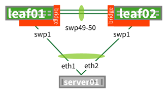 | MLAG (multi-chassis link aggregation) uses both uplinks at the same time. VRR enables both spines to act as gateways simultaneously for HA (high availability) and active-active mode (both are used at the same time). |
Benefits | Considerations |
|---|---|
| 100% of links utilized |
|
| Active-Active Mode | Active-Passive Mode | L2 to L3 Demarcation | More Information |
|---|---|---|---|
| VRR | None |
|
|
Example Configuration
auto bridge
iface bridge
  bridge-vlan-aware yes
  bridge-ports host-01 peerlink
  bridge-vids 1-2000
  bridge-stp on

auto bridge.10
iface bridge.10
  address 172.16.1.2/24
  address-virtual 44:38:39:00:00:10 172.16.1.1/24

auto peerlink
iface peerlink
    bond-slaves glob swp49-50

auto peerlink.4094
iface peerlink.4094
    address 169.254.1.1/30
    clagd-enable yes
    clagd-peer-ip 169.254.1.2
    clagd-system-mac 44:38:39:FF:40:94

auto host-01
iface host-01
  bond-slaves swp1
  clag-id 1
  {bond-defaults removed for brevity}
auto bond0
iface bond0 inet manual
  bond-slaves eth0 eth1
  {bond-defaults removed for brevity}

auto bond0.10
iface bond0.10 inet manual

auto vm-br10
iface vm-br10 inet manual
  bridge-ports bond0.10 vnet0
Layer 3 - Single-attached Hosts
Example | Summary |
|---|---|
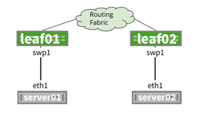 | The server (physical host) has only has one link to one ToR switch. |
Benefits | Considerations |
|---|---|
|
|
FHR (First Hop Redundancy) | More Information |
|---|---|
| No redundancy for ToR, uses single ToR as gateway. | For additional bandwidth, links between host and leaf can be bonded. |
Example Configuration
/etc/network/interfaces file
auto swp1
iface swp1
  address 172.16.1.1/30
/etc/frr/frr.conf file
router ospf
  router-id 10.0.0.11
interface swp1
  ip ospf area 0
/etc/network/interfaces file
auto swp1
iface swp1
  address 172.16.2.1/30
/etc/frr/frr.conf file
router ospf
  router-id 10.0.0.12
interface swp1
  ip ospf area 0
auto eth1
iface eth1 inet static
  address 172.16.1.2/30
  up ip route add 0.0.0.0/0 nexthop via 172.16.1.1
auto eth1
iface eth1 inet static
  address 172.16.2.2/30
  up ip route add 0.0.0.0/0 nexthop via 172.16.2.1
Layer 3 - Redistribute Neighbor
Example | Summary |
|---|---|
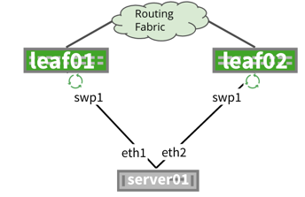 | The Redistribute neighbor daemon grabs ARP entries dynamically and uses the redistribute table for FRRouting to take these dynamic entries and redistribute them into the fabric. |
Benefits | Considerations |
|---|---|
| Configuration in FRRouting is simple (route map plus redistribute table) |
|
| FHR (First Hop Redundancy) | More Information |
|---|---|
|
Layer 3 - Routing on the Host
Example | Summary |
|---|---|
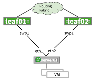 | Routing on the host means there is a routing application (such as FRRouting, either on the bare metal host (no VMs or containers) or the hypervisor (for example, Ubuntu with KVM). This is highly recommended by the Professional Services team. |
Benefits | Considerations |
|---|---|
|
|
FHR (First Hop Redundancy) | More Information |
|---|---|
|
Layer 3 - Routing on the VM
Example | Summary |
|---|---|
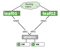 | Instead of routing on the hypervisor, each virtual machine uses its own routing stack. |
Benefits | Considerations |
|---|---|
In addition to routing on host:
|
|
FHR (First Hop Redundancy) | More Information |
|---|---|
|
Layer 3 - Virtual Router
Example | Summary |
|---|---|
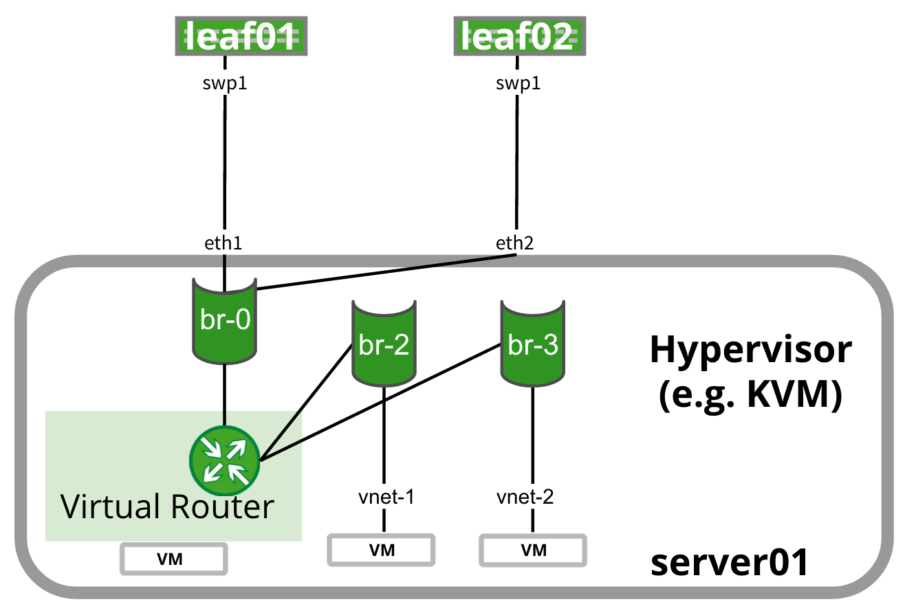 | Virtual router (vRouter) runs as a VM on the hypervisor or host and sends routes to the ToR using BGP or OSPF. |
Benefits | Considerations |
|---|---|
In addition to routing on a host:
|
|
FHR (First Hop Redundancy) | More Information |
|---|---|
|
Layer 3 - Anycast with Manual Redistribution
Example | Summary |
|---|---|
 | In contrast to routing on the host (preferred), this method allows you to route to the host. The ToRs are the gateway, as with redistribute neighbor, except because there is no daemon running, you must manually configure the networks under the routing process. There is a potential to black hole unless you run a script to remove the routes when the host no longer responds. |
Benefits | Considerations |
|---|---|
|
|
| FHR (First Hop Redundancy) |
|---|
| The gateways are the ToRs, exactly like redistribute neighbor with an equal cost route installed. |
Example Configuration
/etc/network/interfaces file
auto swp1
iface swp1
  address 172.16.1.1/30
/etc/frr/frr.conf file
router ospf
  router-id 10.0.0.11
interface swp1
  ip ospf area 0
/etc/network/interfaces file
auto swp2
iface swp2
  address 172.16.1.1/30
/etc/frr/frr.conf file
router ospf
  router-id 10.0.0.12
interface swp1
  ip ospf area 0
auto lo
iface lo inet loopback

auto lo:1
iface lo:1 inet static
  address 172.16.1.2/32
  up ip route add 0.0.0.0/0 nexthop via 172.16.1.1 dev eth0 onlink nexthop via 172.16.1.1 dev eth1 onlink

auto eth1
iface eth2 inet static
  address 172.16.1.2/32

auto eth2
iface eth2 inet static
  address 172.16.1.2/32
Layer 3 - EVPN with Symmetric VXLAN Routing
Symmetric VXLAN routing is configured directly on the ToR, using EVPN for both VLAN and VXLAN bridging as well as VXLAN and external routing.
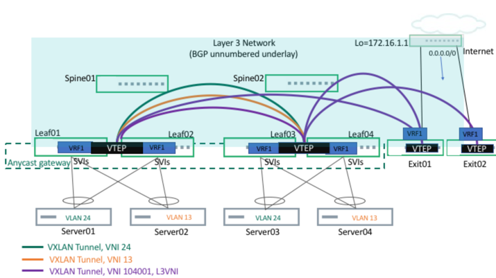
Each server is configured on a VLAN, with a total of two VLANs for the setup. MLAG is also set up between servers and the leafs. Each leaf is configured with an anycast gateway and the servers default gateways are pointing towards the corresponding leaf switch IP gateway address. Two tenant VNIs (corresponding to two VLANs/VXLANs) are bridged to corresponding VLANs.
Benefits | Considerations |
|---|---|
| Needs MLAG (with the same considerations as the MLAG section above). |
| Active-Active Mode | Active-Passive Mode | Demarcation | More Information |
|---|---|---|---|
| VRR | None | ToR layer |
Example /etc/network/interfaces File Configuration
# Loopback interface
auto lo
iface lo inet loopback
  address 10.0.0.11/32
  clagd-vxlan-anycast-ip 10.0.0.112
  alias loopback interface

# Management interface
 auto eth0
 iface eth0 inet dhcp
    vrf mgmt

auto mgmt
iface mgmt
    address 127.0.0.1/8
    address ::1/128
    vrf-table auto

# Port to Server01
auto swp1
iface swp1
  alias to Server01
  # This is required for Vagrant only
  post-up ip link set swp1 promisc on

# Port to Server02
auto swp2
iface swp2
  alias to Server02
  # This is required for Vagrant only
  post-up ip link set swp2 promisc on

# Port to Leaf02
auto swp49
iface swp49
  alias to Leaf02
  # This is required for Vagrant only
  post-up ip link set swp49 promisc on

# Port to Leaf02
auto swp50
iface swp50
  alias to Leaf02
  # This is required for Vagrant only
  post-up ip link set swp50 promisc on

# Port to Spine01
auto swp51
iface swp51
  mtu 9216
  alias to Spine01

# Port to Spine02
auto swp52
iface swp52
  mtu 9216
  alias to Spine02

# MLAG Peerlink bond
auto peerlink
iface peerlink
  mtu 9000
  bond-slaves swp49 swp50

# MLAG Peerlink L2 interface.
# This creates VLAN 4094 that only lives on the peerlink bond
# No other interface will be aware of VLAN 4094
auto peerlink.4094
iface peerlink.4094
  address 169.254.1.1/30
  clagd-peer-ip 169.254.1.2
  clagd-backup-ip 10.0.0.12
  clagd-sys-mac 44:39:39:ff:40:94
  clagd-priority 100

# Bond to Server01
auto bond01
iface bond01
  mtu 9000
  bond-slaves swp1
  bridge-access 13
  clag-id 1

# Bond to Server02
auto bond02
iface bond02
  mtu 9000
  bond-slaves swp2
  bridge-access 24
  clag-id 2

# Define the bridge for STP
auto bridge
iface bridge
  bridge-vlan-aware yes
  # bridge-ports includes all ports related to VxLAN and CLAG.
  # does not include the Peerlink.4094 subinterface
  bridge-ports bond01 bond02 peerlink vni13 vni24 vxlan4001
  bridge-vids 13 24
  bridge-pvid 1

# VXLAN Tunnel for Server1-Server3 (Vlan 13)
auto vni13
iface vni13
  mtu 9000
  vxlan-id 13
  vxlan-local-tunnelip 10.0.0.11
  bridge-access 13
  mstpctl-bpduguard yes
  mstpctl-portbpdufilter yes

#VXLAN Tunnel for Server2-Server4 (Vlan 24)
auto vni24
iface vni24
  mtu 9000
  vxlan-id 24
  vxlan-local-tunnelip 10.0.0.11
  bridge-access 24
  mstpctl-bpduguard yes
  mstpctl-portbpdufilter yes

auto vxlan4001
iface vxlan4001
    vxlan-id 104001
    vxlan-local-tunnelip 10.0.0.11
    bridge-access 4001

auto vrf1
iface vrf1
   vrf-table auto

#Tenant SVIs - anycast GW
auto vlan13
iface vlan13
    address 10.1.3.11/24
    address-virtual 44:39:39:ff:00:13 10.1.3.1/24
    vlan-id 13
    vlan-raw-device bridge
    vrf vrf1

auto vlan24
iface vlan24
    address 10.2.4.11/24
    address-virtual 44:39:39:ff:00:24 10.2.4.1/24
    vlan-id 24
    vlan-raw-device bridge
    vrf vrf1

#L3 VLAN interface per tenant (for L3 VNI)
auto vlan4001
iface vlan4001
    hwaddress 44:39:39:FF:40:94
    vlan-id 4001
    vlan-raw-device bridge
    vrf vrf1
# Loopback interface
auto lo
iface lo inet loopback
  address 10.0.0.12/32
  clagd-vxlan-anycast-ip 10.0.0.112
  alias loopback interface

# Management interface
auto eth0
iface eth0 inet dhcp
    vrf mgmt

auto mgmt
iface mgmt
    address 127.0.0.1/8
    address ::1/128
    vrf-table auto

# Port to Server01
auto swp1
iface swp1
  alias to Server01
  # This is required for Vagrant only
  post-up ip link set swp1 promisc on

# Port to Server02
auto swp2
iface swp2
  alias to Server02
  # This is required for Vagrant only
  post-up ip link set swp2 promisc on

# Port to Leaf01
auto swp49
iface swp49
  alias to Leaf01
  # This is required for Vagrant only
  post-up ip link set swp49 promisc on

# Port to Leaf01
auto swp50
iface swp50
  alias to Leaf01
  # This is required for Vagrant only
  post-up ip link set swp50 promisc on

# Port to Spine01
auto swp51
iface swp51
  mtu 9216
  alias to Spine01

# Port to Spine02
auto swp52
iface swp52
  mtu 9216
  alias to Spine02

# MLAG Peerlink bond
auto peerlink
iface peerlink
  mtu 9000
  bond-slaves swp49 swp50

# MLAG Peerlink L2 interface.
# This creates VLAN 4094 that only lives on the peerlink bond
# No other interface will be aware of VLAN 4094
auto peerlink.4094
iface peerlink.4094
  address 169.254.1.2/30
  clagd-peer-ip 169.254.1.1
  clagd-backup-ip 10.0.0.11
  clagd-sys-mac 44:39:39:ff:40:94
  clagd-priority 200

# Bond to Server01
auto bond01
iface bond01
  mtu 9000
  bond-slaves swp1
  bridge-access 13
  clag-id 1

# Bond to Server02
auto bond02
iface bond02
  mtu 9000
  bond-slaves swp2
  bridge-access 24
  clag-id 2

# Define the bridge for STP
auto bridge
iface bridge
  bridge-vlan-aware yes
  # bridge-ports includes all ports related to VxLAN and CLAG.
  # does not include the Peerlink.4094 subinterface
  bridge-ports bond01 bond02 peerlink vni13 vni24 vxlan4001
  bridge-vids 13 24
  bridge-pvid 1

auto vxlan4001
iface vxlan4001
     vxlan-id 104001
     vxlan-local-tunnelip 10.0.0.12
     bridge-access 4001

# VXLAN Tunnel for Server1-Server3 (Vlan 13)
auto vni13
iface vni13
  mtu 9000
  vxlan-id 13
  vxlan-local-tunnelip 10.0.0.12
  bridge-access 13
  mstpctl-bpduguard yes
  mstpctl-portbpdufilter yes

#VXLAN Tunnel for Server2-Server4 (Vlan 24)
auto vni24
iface vni24
  mtu 9000
  vxlan-id 24
  vxlan-local-tunnelip 10.0.0.12
  bridge-access 24
  mstpctl-bpduguard yes
  mstpctl-portbpdufilter yes

auto vrf1
iface vrf1
   vrf-table auto

auto vlan13
iface vlan13
    address 10.1.3.12/24
    address-virtual 44:39:39:ff:00:13 10.1.3.1/24
    vlan-id 13
    vlan-raw-device bridge
    vrf vrf1

auto vlan24
iface vlan24
    address 10.2.4.12/24
    address-virtual 44:39:39:ff:00:24 10.2.4.1/24
    vlan-id 24
    vlan-raw-device bridge
    vrf vrf1

#L3 VLAN interface per tenant (for L3 VNI)
auto vlan4001
iface vlan4001
    hwaddress 44:39:39:FF:40:94
    vlan-id 4001
    vlan-raw-device bridge
    vrf vrf1
auto lo
iface lo inet loopback

auto eth0
iface eth0 inet dhcp

auto eth1
iface eth1 inet manual
  bond-master uplink
  # Required for Vagrant
  post-up ip link set promisc on dev eth1

auto eth2
iface eth2 inet manual
  bond-master uplink
  # Required for Vagrant
  post-up ip link set promisc on dev eth2

auto uplink
iface uplink inet static
  mtu 9000
  bond-slaves none
  bond-mode 802.3ad
  bond-miimon 100
  bond-lacp-rate 1
  bond-min-links 1
  bond-xmit-hash-policy layer3+4
  address 10.1.3.101
  netmask 255.255.255.0
  post-up ip route add default via 10.1.3.1
auto lo
iface lo inet loopback

auto eth0
iface eth0 inet dhcp

auto eth1
iface eth1 inet manual
  bond-master uplink
  # Required for Vagrant
  post-up ip link set promisc on dev eth1

auto eth2
iface eth2 inet manual
  bond-master uplink
  # Required for Vagrant
  post-up ip link set promisc on dev eth2

auto uplink
iface uplink inet static
  mtu 9000
  bond-slaves none
  bond-mode 802.3ad
  bond-miimon 100
  bond-lacp-rate 1
  bond-min-links 1
  bond-xmit-hash-policy layer3+4
  address 10.2.4.102
  netmask 255.255.255.0
  post-up ip route add default via 10.2.4.1