VXLAN Active-active Mode
VXLAN active-active mode enables a pair of MLAG switches to act as a single VTEP, providing active-active VXLAN termination for bare metal as well as virtualized workloads.
Terminology
Term | Definition |
|---|---|
| VTEP | The virtual tunnel endpoint. This is an encapsulation and decapsulation point for VXLANs. |
| active-active VTEP | A pair of switches acting as a single VTEP. |
| ToR | The top of rack switch; also referred to as a leaf or access switch. |
| spine | The aggregation switch for multiple leafs. Specifically used when a data center is using a Clos network architecture. Read more about spine-leaf architecture in this white paper. |
| exit leaf | A switch dedicated to peering the Clos network to an outside network; also referred to as a border leaf, service leaf, or edge leaf. |
| anycast | An IP address that is advertised from multiple locations. Anycast enables multiple devices to share the same IP address and effectively load balance traffic across them. With VXLAN, anycast is used to share a VTEP IP address between a pair of MLAG switches. |
| RIOT | Routing in and out of tunnels. A Broadcom feature for routing in and out of tunnels. Allows a VXLAN bridge to have a switch VLAN interface associated with it, and traffic to exit a VXLAN into the layer 3 fabric. Also called VXLAN Routing. |
| VXLAN routing | The industry standard term for the ability to route in and out of a VXLAN. Equivalent to the Broadcom RIOT feature. |
| clagd-vxlan-anycast-ip | The anycast address for the MLAG pair to share and bind to when MLAG is up and running. |
Configure VXLAN Active-active Mode
VXLAN active-active mode requires the following underlying technologies to work correctly.
| Technology | More Information |
|---|---|
| MLAG | Refer to MLAG for more detailed configuration information. Example configurations are provided below. |
| OSPF or BGP | Refer to OSPF or BGP for more detailed configuration information. Example configurations for BGP are provided below. |
| STP | You must enable BPDU filter and BPDU guard in the VXLAN interfaces if STP is enabled in the bridge that is connected to the VXLAN. Example configurations are provided below. |
Active-active VTEP Anycast IP Behavior
You must provision each individual switch within an MLAG pair with a virtual IP address in the form of an anycast IP address for VXLAN data-path termination. The VXLAN termination address is an anycast IP address that you configure as a clagd parameter (clagd-vxlan-anycast-ip) under the loopback interface. clagd dynamically adds and removes this address as the loopback interface address as follows:
- When the switches boot up,
ifupdown2places all VXLAN interfaces in a PROTO_DOWN state. The configured anycast addresses are not configured yet. - MLAG peering takes place and a successful VXLAN interface consistency check between the switches occurs.
clagd(the daemon responsible for MLAG) adds the anycast address to the loopback interface as a second address. It then changes the local IP address of the VXLAN interface from a unique address to the anycast virtual IP address and puts the interface in an UP state.
For the anycast address to activate, you must configure a VXLAN interface on each switch in the MLAG pair.
Failure Scenario Behaviors
Scenario | Behavior |
|---|---|
| The peer link goes down. | The primary MLAG switch continues to keep all VXLAN interfaces up with the anycast IP address while the secondary switch brings down all VXLAN interfaces and places them in a PROTO_DOWN state. The secondary MLAG switch removes the anycast IP address from the loopback interface. |
| One of the switches goes down. | The other operational switch continues to use the anycast IP address. |
clagd is stopped. | All VXLAN interfaces are put in a PROTO_DOWN state. The anycast IP address is removed from the loopback interface and the local IP addresses of the VXLAN interfaces are changed from the anycast IP address to unique non-virtual IP addresses. |
| MLAG peering could not be established between the switches. | clagd brings up all the VXLAN interfaces after the reload timer expires with the configured anycast IP address. This allows the VXLAN interface to be up and running on both switches even though peering is not established. |
| The peer link goes down but the peer switch is up (the backup link is active). | All VXLAN interfaces are put into a PROTO_DOWN state on the secondary switch. |
| The anycast IP address is different on the MLAG peers. | The VXLAN interface is placed into a PROTO_DOWN state on the secondary switch. |
Check VXLAN Interface Configuration Consistency
The active-active configuration for a given VXLAN interface must be consistent between the MLAG switches for correct traffic behavior. MLAG ensures that the configuration consistency is met before bringing up the VXLAN interfaces:
- The anycast virtual IP address for VXLAN termination must be the same on each pair of switches.
- A VXLAN interface with the same VXLAN ID must be configured and administratively up on both switches.
Run the clagctl command to check if any VXLAN switches are in a PROTO_DOWN state.
Configure the Anycast IP Address
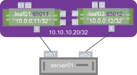
With MLAG peering, both switches use an anycast IP address for VXLAN encapsulation and decapsulation. This enables remote VTEPs to learn the host MAC addresses attached to the MLAG switches against one logical VTEP, even though the switches independently encapsulate and decapsulate layer 2 traffic originating from the host. You can configure the anycast address under the loopback interface, as shown below.
auto lo
iface lo inet loopback
  address 10.0.0.11/32
  clagd-vxlan-anycast-ip 10.10.10.20
auto lo
iface lo inet loopback
  address 10.0.0.12/32
  clagd-vxlan-anycast-ip 10.10.10.20
Example VXLAN Active-Active Configuration
The VXLAN interfaces are configured with individual IP addresses, which clagd changes to anycast upon MLAG peering.
FRRouting Configuration
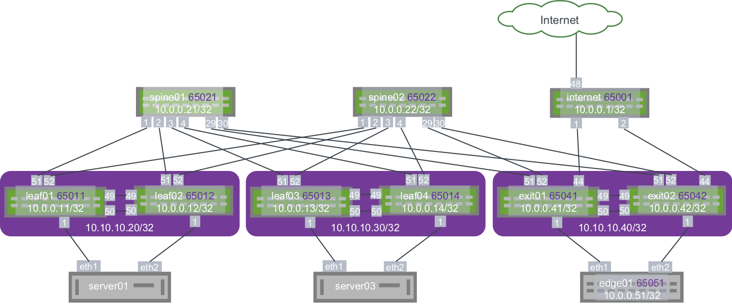
You can configure the layer 3 fabric using BGP or OSPF. The following example uses BGP unnumbered. The MLAG switch configuration for the topology above is:
Layer 3 IP Addressing
The IP address configuration for this example:
auto lo
iface lo inet loopback
  address 10.0.0.21/32

auto eth0
iface eth0 inet dhcp

# downlinks
auto swp1
iface swp1

auto swp2
iface swp2

auto swp3
iface swp3

auto swp4
iface swp4

auto swp29
iface swp29

auto swp30
iface swp30
auto lo
iface lo inet loopback
    address 10.0.0.22/32

auto eth0
iface eth0 inet dhcp

# downlinks
auto swp1
iface swp1

auto swp2
iface swp2

auto swp3
iface swp3

auto swp4
iface swp4

auto swp29
iface swp29

auto swp30
iface swp30
auto lo
iface lo inet loopback
    address 10.0.0.11/32
    clagd-vxlan-anycast-ip 10.10.10.20

auto eth0
iface eth0 inet dhcp

# peerlinks
auto swp49
iface swp49

auto swp50
iface swp50

auto peerlink
iface peerlink
  bond-slaves swp49 swp50

auto peerlink.4094
iface peerlink.4094
  address 169.254.1.1/30
  clagd-peer-ip 169.254.1.2
  clagd-backup-ip 10.0.0.12
  clagd-sys-mac 44:38:39:FF:40:94

# Downlinks
auto swp1
iface swp1

auto bond0
iface bond0
    bond-slaves swp1
    clag-id 1

auto bridge
iface bridge
  bridge-vlan-aware yes
  bridge-ports peerlink bond0 vni10 vni20
  bridge-vids 10 20

auto vlan10
iface vlan10

auto vlan20
iface vlan20

auto vni10
iface vni10
  vxlan-id 10
  vxlan-local-tunnelip 10.0.0.11
  bridge-access 10
  mstpctl-bpduguard yes
  mstpctl-portbpdufilter yes

auto vni20
iface vni20
  vxlan-id 20
  vxlan-local-tunnelip 10.0.0.11
  bridge-access 20
  mstpctl-bpduguard yes
  mstpctl-portbpdufilter yes

# uplinks
auto swp51
iface swp51

auto swp52
iface swp52
auto lo
iface lo inet loopback
    address 10.0.0.12/32
  clagd-vxlan-anycast-ip 10.10.10.20

auto eth0
iface eth0 inet dhcp

# peerlinks
auto swp49
iface swp49

auto swp50
iface swp50

auto peerlink
iface peerlink
  bond-slaves swp49 swp50

auto peerlink.4094
iface peerlink.4094
  address 169.254.1.2/30
  clagd-peer-ip 169.254.1.1
  clagd-backup-ip 10.0.0.11
  clagd-sys-mac 44:38:39:FF:40:94

# Downlinks
auto swp1
iface swp1

auto bond0
iface bond0
    bond-slaves swp1
    clag-id 1

auto bridge
iface bridge
  bridge-vlan-aware yes
  bridge-ports peerlink bond0 vni10 vni20
  bridge-vids 10 20

auto vlan10
iface vlan10

auto vlan20
iface vlan20

auto vni10
iface vni10
  vxlan-id 10
  vxlan-local-tunnelip 10.0.0.12
  bridge-access 10
  mstpctl-bpduguard yes
  mstpctl-portbpdufilter yes

auto vni20
iface vni20
  vxlan-id 20
  vxlan-local-tunnelip 10.0.0.12
  bridge-access 20
  mstpctl-bpduguard yes
  mstpctl-portbpdufilter yes

# uplinks
auto swp51
iface swp51

auto swp52
iface swp52
auto lo
iface lo inet loopback
  address 10.0.0.13/32
  clagd-vxlan-anycast-ip 10.10.10.30

auto eth0
iface eth0 inet dhcp

# peerlinks
auto swp49
iface swp49

auto swp50
iface sw50p

auto peerlink
iface peerlink
  bond-slaves swp49 swp50

auto peerlink.4094
iface peerlink.4094
  address 169.254.1.1/30
  clagd-peer-ip 169.254.1.2
  clagd-backup-ip 10.0.0.14
  clagd-sys-mac 44:38:39:FF:40:95

# Downlinks
auto swp1
iface swp1

auto bond0
iface bond0
    bond-slaves swp1
    clag-id 1

auto bridge
iface bridge
  bridge-vlan-aware yes
  bridge-ports peerlink bond0 vni10 vni20
  bridge-vids 10 20

auto vlan10
iface vlan10

auto vlan20
iface vlan20

auto vni10
iface vni10
  vxlan-id 10
  vxlan-local-tunnelip 10.0.0.13
  bridge-access 10
  mstpctl-bpduguard yes
  mstpctl-portbpdufilter yes

auto vni20
iface vni20
  vxlan-id 20
  vxlan-local-tunnelip 10.0.0.13
  bridge-access 20
  mstpctl-bpduguard yes
  mstpctl-portbpdufilter yes

# uplinks
auto swp51
iface swp51

auto swp52
iface swp52
auto lo
iface lo inet loopback
  address 10.0.0.14/32
  clagd-vxlan-anycast-ip 10.10.10.30

auto eth0
iface eth0 inet dhcp

# peerlinks
auto swp49
iface swp49

auto swp50
iface swp50

auto peerlink
iface peerlink
  bond-slaves swp49 swp50

auto peerlink.4094
iface peerlink.4094
  address 169.254.1.2/30
  clagd-peer-ip 169.254.1.1
  clagd-backup-ip 10.0.0.13
  clagd-sys-mac 44:38:39:FF:40:95

# Downlinks
auto swp1
iface swp1

auto bond0
iface bond0
    bond-slaves swp1
    clag-id 1

auto bridge
iface bridge
  bridge-vlan-aware yes
  bridge-ports peerlink bond0 vni10 vni20
  bridge-vids 10 20

auto vlan10
iface vlan10

auto vlan20
iface vlan20

auto vni10
iface vni10
  vxlan-id 10
  vxlan-local-tunnelip 10.0.0.14
  bridge-access 10
  mstpctl-bpduguard yes
  mstpctl-portbpdufilter yes

auto vni20
iface vni20
  vxlan-id 20
  vxlan-local-tunnelip 10.0.0.14
  bridge-access 20
  mstpctl-bpduguard yes
  mstpctl-portbpdufilter yes

# uplinks
auto swp51
iface swp51

auto swp52
iface swp52
Host Configuration
In this example, the servers are running Ubuntu 14.04. A layer2 bond must be mapped from server01 and server03 to the respective switch. In Ubuntu, you use subinterfaces.
auto lo
iface lo inet loopback

auto lo
iface lo inet static
  address 10.0.0.31/32

auto eth0
iface eth0 inet dhcp

auto eth1
iface eth1 inet manual
    bond-master bond0

auto eth2
iface eth2 inet manual
    bond-master bond0

auto bond0
iface bond0 inet static
  bond-slaves none
  bond-miimon 100
  bond-min-links 1
  bond-mode 802.3ad
  bond-xmit-hash-policy layer3+4
  bond-lacp-rate 1
  address 172.16.1.101/24

auto bond0.10
iface bond0.10 inet static
  address 172.16.10.101/24

auto bond0.20
iface bond0.20 inet static
  address 172.16.20.101/24
auto lo
iface lo inet loopback

auto lo
iface lo inet static
  address 10.0.0.33/32

auto eth0
iface eth0 inet dhcp

auto eth1
iface eth1 inet manual
    bond-master bond0

auto eth2
iface eth2 inet manual
    bond-master bond0

auto bond0
iface bond0 inet static
  bond-slaves none
  bond-miimon 100
  bond-min-links 1
  bond-mode 802.3ad
  bond-xmit-hash-policy layer3+4
  bond-lacp-rate 1
  address 172.16.1.103/24

auto bond0.10
iface bond0.10 inet static
  address 172.16.10.103/24

auto bond0.20
iface bond0.20 inet static
  address 172.16.20.103/24
Troubleshooting
Run the clagctl command to show MLAG behavior and any inconsistencies that might arise between a MLAG pair.
cumulus@leaf01$ clagctl
The peer is alive
      Our Priority, ID, and Role: 32768 44:38:39:00:00:35 primary
    Peer Priority, ID, and Role: 32768 44:38:39:00:00:36 secondary
          Peer Interface and IP: peerlink.4094 169.254.1.2
                VxLAN Anycast IP: 10.10.10.30
                      Backup IP: 10.0.0.14 (inactive)
                      System MAC: 44:38:39:ff:40:95
CLAG Interfaces
Our Interface      Peer Interface     CLAG Id   Conflicts     Proto-Down Reason
----------------   ----------------   -------   -----------   -----------------
           bond0   bond0              1         -             -
         vxlan20   vxlan20            -         -             -
          vxlan1   vxlan1             -         -             -
         vxlan10   vxlan10            -         -             -
The additions to normal MLAG behavior are:
Output | Explanation |
|---|---|
VXLAN Anycast IP: 10.10.10.30 | The anycast IP address being shared by the MLAG pair for VTEP termination is in use and is 10.10.10.30. |
Conflicts: - | There are no conflicts for this MLAG Interface. |
Proto-Down Reason: - | The VXLAN is up and running (there is no Proto-Down). |
In the following example the vxlan-id on VXLAN10 is switched to the wrong vxlan-id. When you run the clagctl command, VXLAN10 is down because this switch is the secondary switch and the peer switch takes control of VXLAN. The reason code is vxlan-single indicating that there is a vxlan-id mis-match on VXLAN10.
cumulus@leaf02$ clagctl
The peer is alive
    Peer Priority, ID, and Role: 32768 44:38:39:00:00:11 primary
      Our Priority, ID, and Role: 32768 44:38:39:00:00:12 secondary
          Peer Interface and IP: peerlink.4094 169.254.1.1
                VxLAN Anycast IP: 10.10.10.20
                      Backup IP: 10.0.0.11 (inactive)
                      System MAC: 44:38:39:ff:40:94
CLAG Interfaces
Our Interface      Peer Interface     CLAG Id   Conflicts      Proto-Down Reason
----------------   ----------------   -------   ------------   -----------------
           bond0   bond0              1         -              -
         vxlan20   vxlan20            -         -              -
          vxlan1   vxlan1             -         -              -
         vxlan10   -                  -         -              vxlan-single
Considerations
Use VLAN for Peer Link Only Once
Do not reuse the VLAN for the peer link layer 3 subinterface for any other interface in the system. A high VLAN ID value is recommended. For more information on VLAN ID ranges, refer to the VLAN-aware bridge chapter.
Bonds with Vagrant in Cumulus VX
Bonds (or LACP Etherchannels) fail to work in a Vagrant configuration unless the link is set to promiscuous mode. This is a limitation on virtual topologies only and is not needed on real hardware.
auto swp49
iface swp49
  #for vagrant so bonds work correctly
  post-up ip link set $IFACE promisc on

auto swp50
iface swp50
  #for vagrant so bonds work correctly
  post-up ip link set $IFACE promisc on
For more information on using Cumulus VX and Vagrant, refer to the Cumulus VX documentation.