Troubleshoot Layer 1
This chapter describes how to troubleshoot layer 1 issues that can affect the port modules connecting a switch to a network.
Background - High Speed Ethernet Technologies
Before we describe various troubleshooting methods, it’s helpful to understand some background information.
Specifications
The following specifications are useful in understanding and troubleshooting layer 1 problems:
- IEEE 802.3 specifications define the technologies and link characteristics of the various types and speeds of Ethernet technologies.
- SFF MSA specifications define the specifics of the hardware construction and implementations of features of the SFP and QSFP modules themselves.
Form Factors
Modern Ethernet modules come in one of two form factors:
- Small Form factor Pluggables (SFP)
- Quad Small Form factor Pluggables (QSFP)
Each contains an EEPROM with information about the module’s capabilities, and various groups of required or optional registers to query or control aspects of the module when needed. The main values are decoded in the output from the ethtool -m <swp> command.
The memory locations for the various fields in the EEPROM and the common registers are defined in the SFF/MSA specifications:
- SFP: SFF-8472: Management Interface for SFP+ (PDF)
- QSFP: SFF-8636 Management Interface for 4-lane Modules and Cables (PDF)
Identifiers used in the first byte of the module memory map:
- 0x03: SFP/SFP+/SFP28 - One 10G or 25G lane - Small Form factor Pluggable
- 0x0d: QSFP+ - Four 10G lanes - Quad SFP (40G total)
- 0x11: QSFP28 - Four 25G or 50G lanes (100G or 200G total) - Quad SFP with 25G or 50G lanes
- 0x18: QSFP-DD - Eight 50G lanes (400G total) - Quad SFP with a recessed extra card-edge connector to enable 8 lanes of 50G
Encoding
There are two parts of high-speed Ethernet that are grouped under encoding in the output from the ethtool -m <swp> command:
The way to represent bits on the wire or optical fiber:
- NRZ (also known as PAM2): Has two voltage (or laser) levels signifying a 0 and 1. Negative voltage level = 0, positive voltage = 1. Used on all Ethernet technologies below lane speeds of 50Gbps.
- PAM4 encoding: Has four signal level signifying two bits (00,01,10,11). These level are much closer together than the levels in NRZ/PAM2, so signal integrity is an even greater concern. PAM4 encoding is used on 50G lanes.
The way the bits are joined together into a frame to be able to facilitate functions like clock recovery and error checking and correction:
- 64B/66B: Two control bits with a 1/0 transition are added to the front of a 64 bit frame to ensure that the clock can sync every 66 bits.
- RS-FEC encoding (528,514) or (544,514): Uses 14 or 30 bits to enable correction of bit errors on the receive side (see the FEC section below).
- BaseR FEC encoding: Steals a bit in the 64B/66B control word to re-encode and add a smaller level of error correction than RS-FEC.
The relationship between lane speed and encoding methods is described in this table:
| Lane Speed | Encoding |
|---|---|
| 10G | Uses 64B/66B framing then encoded in NRZ — actually 10.3125 Gbps on the wire. |
| 25G | Uses 64B/66B framing then encoded in NRZ — actually 25.78125 Gbps on the wire. Can also use RS-FEC (528,514) or Base-R FEC. |
| 50G | Uses PAM4 encoding and RS-FEC (544,514). |
The SerDes (Serial/Deserializer) is the component in the port that converts byte data to and from a set of bit streams (lanes), where:
- SFP ports use 1 lane
- QSFP ports use 4 lanes
- QSFP-DD ports use 8 lanes
On the ASIC, the 40G, 100G and 200G SerDes devices are 4 lanes; 400G SerDes uses 8 lanes. So an SFP port is actually one lane on a four lane SerDes. Depending on the platform design, this sometimes affects how SFP ports can be configured and broken out.
Combining these two ideas, port speeds are created using the following formulas:
| Port Speed | Number of Lanes |
|---|---|
| 1G | One 10G or 25G lane clocked at 1G. Or, on a 1G fixed copper switch, a 1G lane. |
| 10G | One 10G lane. |
| 25G | One 25G lane. |
| 40G | Four 10G lanes. |
| 50G | Two 25G lanes (NRZ) or one 50G lane (PAM4). |
| 100G | Four 25G lanes (100G-SR4/CR4 NRZ) or two 50G lanes (100G-CR2 PAM4). |
| 200G | Four 50G lanes. |
| 400G | Eight 50G lanes. |
Active and Passive Modules and Cables
From the point of view of the port, modules and cables can be classified as either active or passive.
Active cables and modules contain transmitters that regenerate the bit signals over the cable. All optical modules are active. 10/100/1000BaseT and 10GBaseT are active modules and contain an onboard PHY that handles the BaseT autonegotiation and TX/RX to the remote BaseT device. For active modules, the port only has to provide a TX signal with a base level of power to the module, and the module uses the power it receives on the port power bus to regenerate the signal to the remote side.
Although some copper cable assemblies are active, they are extremely rare.
Passive cables (copper DACs) directly connect the port side of the module to the copper twinax media on the other side of the module in the assembly. The port TX lines provide the power to drive the signal to the remote end. The port goes through a training sequence with the remote end port to tune the power TX and RX parameters to optimize the received signal and ensure correct clock and data recovery at each RX end.
Compliance Codes, Ethernet Type, Ethmode Type, Interface Type
These four terms essentially mean the same thing: the type of Ethernet technology that the module implements.
In order for the port to know the characteristics of the module that is inserted, the SFP or QSFP module EEPROMs have a standardized set of data to describe the module characteristics. These values appear in the output of ethtool -m <swp>.
The compliance codes describe the type of Ethernet technology the module implements. Examples include 1000Base-T, 10GBase-SR, 10GBase-CR, 40GBase-SR4 and 100GBase-CR4.
The first part of the compliance code gives the full line rate speed of the technology.
The last part of the compliance code specifies the Ethernet technology and the number of lanes used:
- -T: Twisted pair.
- CR: Copper twinax (passive DAC). CR4 uses a bundle of 4 twinax cables for 4 lanes, CR2 uses 2 cables, CR uses 1.
- SR: Optical short range. SR4 uses a bundle of 4 fibers for 4 lanes.
- LR: Optical long range. LR4 uses 4 wavelengths over one fiber pair to transmit 4 lanes over long distances (kilometers).
- xWDM (SWDM, CWDM, DWDM): Optical wavelength multiplexed technologies (various). Multiple lanes are transmitted by different wavelengths.
An active module with a passive module compliance code and vice versa would cause the port to be set up incorrectly and may affect signal integrity.
Some modules have vendor specific coding, are older, or are using a proprietary vendor technology that is not listed in the standards. As a result, they are not recognized by default and need to be overridden to the correct compliance code. On Mellanox platforms, the port firmware automatically overrides certain supported modules to the correct compliance code. On Broadcom platforms, the /usr/share/cumulus/portwd.conf file contains known overrides for certain modules. On Broadcom platforms, the user can also create an override file in /etc/cumulus/portwd.conf to specify that a module is best represented by a particular compliance code.
The override file uses the vendor OUI (preferred, more reliable) or the vendor name, plus the vendor PN — all from the module EEPROM — to specify the correct override compliance code of the module. For example:
[cables]
44:7c:7f,C41MF=40g-sr4
DELL EMC,C41MF=40g-sr4
Digital Diagnostic Monitoring/Digital Optical Monitoring (DDM/DOM)
DDM/DOM is an optional capability that vendors can implement on their optical transceivers to display to the user various useful measurements about the optical power. The values are generally reliable within a 10% tolerance. A value of 0.0000 generally indicates the value is not implemented by the vendor.
The most useful DDM/DOM values when troubleshooting a problem link are:
- RX optical power (receiver signal average optical power)
- TX optical power (laser output power)
The location of DDM/DOM fields are standardized, so if DDM/DOM capability is present on a module, the values are displayed in the output of ethtool -m <swp>.
For each DDM/DOM value there can be thresholds to mark a high or low warning or an alarm when the value exceeds that threshold.
Generally, an alarm value indicates the level required for the signal to be within the vendor’s design tolerance, and the warning level is a little bit closer to expected norms.
When a warning or alarm is triggered, the flag flips from Off to On. Reading that value with ethtool -m or NVIDIA NetQ (or some other monitoring software) resets this flag back to Off after it is read.
Autonegotiation
The definition of autonegotiation (or autoneg) has changed slightly with each new Ethernet speed and technology. As a result, there are 3 different types of autoneg (IEEE 802.3 clauses 28, 37, 73), which apply to various Ethernet technologies that Cumulus Linux supports:
- 10/100/1000/10GBASE-T (twisted pair, clause 28): The original Ethernet autoneg, which negotiates speed and duplex (full/half) and flow control (link pause) on full-duplex. Mandatory for 1G/10G data rates over twisted pair.
- 1000BASE-X (optical, clause 37): Detects unidirectional link conditions (no RX on one side). If a unidirectional link condition occurs, clause 37 autoneg signals the port to bring the link down; this avoids blackholing traffic.
- 40G/100G/25G/50G/200G/400GBASE-CR (DAC, clause 73): Negotiates speed, performs link training to improve the bit error rate (BER) and negotiates FEC.
Many Ethernet technologies used in Cumulus Linux switches do not have autoneg capability. Notably:
- All 10G DAC and optical links do not have autonegotiation; only 10GBASE-T and backplane links have autoneg standards. Backplane links do not exist on Cumulus Linux switch ports.
- All optical links except 1G optical do not have autonegotiation.
Thus, only about half of all modern link types even support autoneg, leading to much confusion regarding whether to enable or disable autoneg.
The next three subsections provide guidance on when and how to enable autonegotiation.
Ethernet Link Types and Autonegotiation
1000BASE-T and 10GBASE-T fixed copper ports require autonegotiation for 1G and 10G speeds. This is the default setting and cannot be disabled for 1G speeds. Disabling autoneg on these ports requires setting the speed to 100Mbps or 10Mbps and the correct duplex setting.
1000BASE-T SFPs have an onboard PHY that does the autonegotiation automatically on the RJ45 side without involving the port. Do not change the default autoneg setting on these ports; on Mellanox switches, autoneg is ON while on Broadcom switches, autoneg is OFF.
For 1000BASE-X, autonegotiation is highly recommended on 1G optical links to detect unidirectional link failures.
For all other optical modules besides 1000BASE-X, there is no autonegotiation standard.
For 10G DACs, there is no autonegotiation.
For DAC cables on speeds higher than 25G, autonegotiation is unnecessary, but is useful because it can improve signal integrity by link training. It also negotiates speed and FEC, but this is less useful since the neighbor speed and FEC is usually known.
On Broadcom platforms, when autonegotiation is enabled, the output of sudo l1-show <swp> displays the local advertised autonegotiation capabilities and the remote advertised autonegotiation capabilities, provided the link is up.
General Autonegotiation Guidance
- When autoneg is supported on an Ethernet type, both sides of the link must be configured with the same autoneg setting.
- Cumulus Linux sets a default for autoneg and/or speed, duplex and FEC for each port based on the ASIC and port speed. On Mellanox platforms running Cumulus Linux, autoneg defaults to ON. On Broadcom platforms running Cumulus Linux, autoneg and FEC default to OFF, and the maximum speed for the port as defined in
ports.conf. - If autoneg is OFF — which is called force mode — then speed, duplex and FEC must also be specified if a non-default value for the port is desired. If autoneg is ON, then speed, duplex and FEC should not be specified. The only exception to this is for 1000BASE-X optical interfaces, where speed is 1000 and autoneg is ON in order to get unidirectional link detection.
- If autoneg is enabled on a link type that does not support autoneg, the port enters autodetect mode (see the next section) to try and determine the most likely speed and FEC settings to bring the link up. This feature is usually successful, but if the link does not come up, it may be necessary to disable autoneg and set these link settings manually.
- There is no concept of autoneg of MTU. To change the MTU from the default setting, configure it explicitly.
- Generally, the duplex setting can be ignored except on 10M/100M links. The default is Full. Although it can be configured, it has no option except Full on speeds higher than 1G and is autonegotiated on 1000BASE-T links.
Autodetect
As a result of the confusion about when autoneg applies to a link type, many Ethernet software vendors, including Cumulus Linux, allow autoneg ON to be configured on every interface type. When autonegotiation is ON, but is not supported on a link type, the port software tries to determine the most likely link settings to bring the link up. Cumulus Linux calls this feature autodetect, but it is not directly configurable.
When autonegotiation is enabled on a port, the behavior is as follows:
- On Mellanox platforms, when autoneg is ON, the port is always in autodetect mode. The port steps through a list of possible autoneg, speed and FEC settings for the port and module combination until the link comes up. The default configuration is autoneg ON, which essentially means autodetect on for Mellanox switches.
- On Broadcom platforms, if autoneg is available on the Ethernet type, it is enabled. On Ethernet types that do not support autoneg, Cumulus Linux treats autoneg as autodetect. At the port hardware level it sets:
- Autoneg to OFF.
- Speed to the max speed defined in
ports.conf. - FEC to RS on 100G, FEC BaseR on 25G, and OFF everywhere else.
Autodetect is a local feature. The neighbor is assumed to either be configured with autoneg off and speed, duplex and FEC set manually, or using some equivalent algorithm to determine the correct speed, duplex and FEC settings.
To see the user configured settings for autoneg, speed, duplex and FEC versus the actual operational state on the port hardware, use the l1-show command.
The autodetect feature is usually successful, but if the link does not come up, it may be necessary to disable autonegotiation and configure the link settings manually.
FEC
Forward Error Correction (FEC) is an algorithm used to correct bit errors along a medium. FEC encodes the data stream so that the remote device can correct a certain number of bit errors by decoding the stream.
The target IEEE bit error rate (BER) in high-speed Ethernet is 10-12. At 25G lane speeds and above, this may not be achievable without error correction, depending on the media type and length. See Switch Port Attributes for a more detailed discussion of FEC requirements for certain cable types.
Both sides of a link must have the same FEC encoding algorithm enabled for the link to come up. If both sides appear to have a working signal path but the link is down, there could be an autoneg mismatch or FEC mismatch in the configuration.
FEC Encoding Algorithms and Settings
- The Reed-Solomon RS-FEC(528,514) algorithm adds 14 bits of encoding information to a 514 bit stream. It replaces and uses the same amount of overhead in the 64B/66B encoding, so that the bit rate is not affected. It can correct 7 bit errors in a 514 bit stream. RS(528,514) is used on 25G (NRZ) lanes, including 25G, 50G-CR2 and 100G-SR4/CR4 interfaces.
- The Reed-Solomon RS-FEC(544,514) algorithm adds 30 bits of overhead to correct 14+ bit errors per 514 bits. FEC RS is required on 50G (PAM4) lanes, hence, all 200G, 400G, 100G-CR2 and 50G-CR interfaces.
- Base-R (also known as FireCode/FC) FEC adds 32 bits per 32 blocks of 64B/66B to correct 11 bits per 2048 bits. It replaces one bit per block, so it uses the same amount of overhead as 64B/66B encoding. It is used in 25G interfaces only. The algorithm executes faster than the RS-FEC algorithm, so latency is reduced. Both RS-FEC and Base-R FEC are implemented in hardware.
- None/Off: FEC is optional and is often useful on 25G lanes, which includes 100G-SR4/CR4 and 50G-CR2 links. If the cable quality is good enough to achieve a BER of 10-12 without FEC, then there is no reason to enable it. 10G/40G links should never require FEC. If a 10G/40G link has errors, replace the cable or module that is causing the error. None/Off is the default setting on Broadcom switches since autoneg OFF is the default setting.
- Auto: FEC can be autonegotiated between 2 devices. When autoneg is ON, the default FEC setting is auto to enable FEC capability information to be sent and received with the neighbor. The port FEC active/operational setting is set to the result of the negotiation. Auto is the default setting on Mellanox switches since autoneg ON is the default setting.
In some cases, the configured value may be different than the operational value. In such cases, the l1-show command displays both values. For example:
- Configured: Auto, Operational: RS.
- Configured: RS, but link is down, so Operational is: None/Off
Signal Integrity
The goal of Ethernet protocols and technologies is to enable the bits generated on one side of a link to be received correctly on the other side. The next two sections provide information as to what might be happening on the link level when the link is down or bits are not being received correctly.
Link State: RX Power, Signal Detection, Signal Lock, Carrier Detection, RX Fault
Various characteristics show the state of a link. All characteristics may not be available to display on all platforms.
- RX power: On optical modules with DDM/DOM capabilities, the module shows the power level of the received signal. Note that a module can receive a signal with plenty of power, but still not be able to recover the data from a signal because it is distorted.
- Signal detected: A signal is received from the remote device on the local port receiver.
- Signal lock: The local port receiver is locked onto a good signal that is received from the remote side.
- Carrier detected: Both ends of the link are able to understand the data being sent to them. The link should be up on both sides.
- RX fault (None, Local, Remote or Local/Remote): The local end or the remote end is alerting that it is not receiving and/or understanding a good signal and bit stream.
- Local fault indicates the local end does not have signal lock or cannot understand the data sent to it on its RX path.
- Remote fault indicates that the local end RX path has signal lock and can understand the bit stream from the neighbor, but the remote neighbor is sending alerts over that working path indicating that it has no signal lock or cannot understand the data sent to it over its own RX path.
On Broadcom switches, if both sides are showing signal lock, but not carrier, it could be there is an autoneg mismatch or FEC mismatch in the configuration.
Eyes
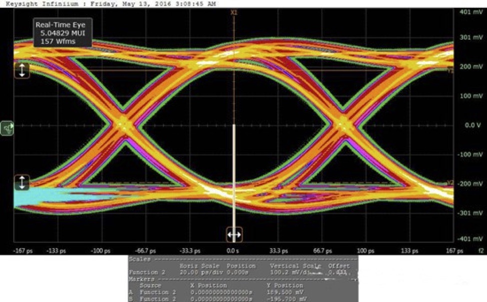
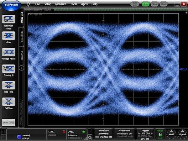
When a 1 or a 0 bit is transmitted across a link, it is represented on the electrical side of the port as either a high voltage level or a low voltage level, respectively. If an oscilloscope is attached to those leads, as the bit stream is transmitted across it, the transitions between 1 and 0 would form a pattern in the shape of an eye.
The farther the distance between the 1 and 0, the more open the eye appears. The better — that is, more open — the eye is, the less likely it is for a bit to be misread. When a bit is misread, it causes a bit-error, which would result in an FCS error on the entire packet being received. A lower eye measurement generally translates to a larger bit error rate (BER). FEC can correct bit errors up to a point.
Eyes are not measured on fixed copper ports, nor are they measured when a link is down.
Each hardware vendor implements some quantitative measurement of eyes and some kind of qualitative measurement.
On a Mellanox switch, the eyes are assigned a height in mV and a grade. As a rule of thumb for speeds below 100G (NRZ encoding), when the grade goes below 4000, the error rate or stability of the link may be negatively impacted.
On a Broadcom switch, the eyes are assigned a value for up, down, left, right (U,D,L,R) measurements from the center of the eye. As a rule of thumb, when the up or down measurement goes below 100 or the left/right measurement goes below 150, the error rate or stability of the link may be negatively impacted.
Note that these rules of thumb are only an indicator when troubleshooting a problem link. A link may have no stability problems with a measurement below these values, and FEC may correct all errors presented on such a link. For some interface types, FEC is required for the very reason to remove errors up to BER levels that are expected on the media.
For 50G lanes (200G- and 400G-capable ports), the link uses PAM4 encoding, which has 3 eyes stacked on top of each other and therefore much smaller eye measurements. The rules of thumb mentioned above do not apply. As noted earlier, FEC is required on these links.
l1-show Command
Because Linux Ethernet tools do not have a unified approach to the various vendor driver implementations and areas that affect layer 1, the l1-show command was added to Cumulus Linux versions 3.7.7 and 4.0.0 in order to show all layer 1 aspects of a Cumulus Linux port and link.
The command must be run as root. The syntax for the command is:
cumulus@switch:~$ sudo l1-show PORTLIST
Here is the output from a 25G DAC link on a Broadcom switch:
cumulus@switch:~$ sudo l1-show swp43
Port:  swp43
  Module Info
      Vendor Name: Mellanox               PN: MCP2M00-A003
      Identifier: 0x03 (SFP)              Type: 25g-cr
  Configured State
      Admin: Admin Up     Speed: 25G      MTU: 9216
      Autoneg: Off                        FEC: Off
  Operational State
      Link Status: Kernel: Up             Hardware: Up
      Speed: Kernel: 25G                  Hardware: 25G
      Autoneg: Off                        FEC: Off
      TX Power (mW): None
      RX Power (mW): None
      Topo File Neighbor: mlx-switch-1, swp43
      LLDP Neighbor:      mlx-switch-1, swp43
  Port Hardware State:
      Rx Fault: None                      Carrier Detect: yes
      Rx Signal: Detect: Y                Signal Lock: Y
      Ethmode Type: 25g-cr                Interface Type: CR
      Speed: 25G                          Autoneg: Off
      MDIX: ForcedNormal, Normal          FEC: Off
      Local Advrtsd: None                 Remote Advrtsd: None
      Eyes: L: 281, R: 296, U: 118, D: 118
Here is the output from the Mellanox 2410 switch on the other side of the same link:
cumulus@2410-switch:~$ sudo l1-show swp43
Port:  swp43
  Module Info
      Vendor Name: Mellanox               PN: MCP2M00-A003
      Identifier: 0x03 (SFP)              Type: 25g-cr
  Configured State
      Admin: Admin Up     Speed: 25G      MTU: 9216
      Autoneg: On                         FEC: Auto
  Operational State
      Link Status: Kernel: Up             Hardware: Up
      Speed: Kernel: 25G                  Hardware: 25G
      Autoneg: On (Autodetect enabld)     FEC: None
      TX Power (mW): None
      RX Power (mW): None
      Topo File Neighbor: bcm-switch-1, swp43
      LLDP Neighbor:      bcm-switch-1, swp43
  Port Hardware State:
      Compliance Code: 100GBASE-CR4 or 25GBASE-CR CA-L
      Cable Type: Passive copper cable
      Speed: 25G                          Autodetect: Enabled
      Eyes: 79                            Grade: 5451
      Troubleshooting Info: No issue was observed.
The output is organized into the following sections:
- Module Info: Shows the basic information about the module, according to the module EEPROM.
- Configured State: Shows the configuration information of the port as defined in the kernel.
- Operational State: Shows the high level details of the actual link status of the port in the hardware and kernel.
- Port Hardware State: Shows the low level port information from the port on the switch ASIC.
Module Information
The vendor name, vendor part number, identifier (QSFP/SFP type), and type (compliance codes) are read from the vendor EEPROM. If a compliance code override is being applied on a Broadcom platform, it is noted here. See Compliance Codes, Ethernet Type, Ethmode Type, Interface type above for an explanation.
Module Info
    Vendor Name: Mellanox               PN: MCP2M00-A003
    Identifier: 0x03 (SFP)              Type: 25g-cr
Configured State
The configured state reflects the configuration that has been applied to the kernel via ifupdown2 or NCLU. The switchd daemon translates the kernel state to the platform hardware state and keeps them in sync.
Configured State
    Admin: Admin Up     Speed: 25G      MTU: 9216
    Autoneg: On                         FEC: Auto
- Admin state:
- Admin Up means the kernel has enabled the port via NCLU,
ifupdown2, or temporarily viaip set line <swp> up. - Admin Down means the kernel has disabled the port.
- Admin Up means the kernel has enabled the port via NCLU,
- Speed:
- The configured speed in the kernel.
- The maximum speed is set in
/etc/cumulus/ports.conf. - The speed can be lowered using NCLU or
ifupdown2. - If autonegotiation is enabled, this output displays the negotiated or autodetected speed.
- MTU: The configured MTU setting in the kernel.
- Autoneg: The configured autoneg state in the kernel. See the discussion in the Autonegotiation section for more information.
- FEC: The configured state of FEC in the kernel. See the discussion in the FEC section above for more information.
Operational State
The operational state shows the current state of the link in the kernel and in the switch hardware.
  Operational State
      Link Status: Kernel: Up             Hardware: Up
      Speed: Kernel: 25G                  Hardware: 25G
      Autoneg: On (Autodetect enabld)     FEC: None
      TX Power (mW): None
      RX Power (mW): None
      Topo File Neighbor: switch-1, swp43
      LLDP Neighbor:      switch-1, swp43
- Link Status and Speed: Normally the kernel state and hardware state should match, unless the link is in some unstable or transitory state.
- Autoneg/Autodetect: See the discussion in the Autonegotiation section above for more information about the meaning of these values.
- FEC: The operational state of FEC on the link. See the discussion in the FEC section above for more information about the meaning of these values.
- TX Power/RX Power: These values are read from the module DDM/DOM fields to indicate the optical power strength measured on the module if the module implements the feature. Sometimes both are supported, sometimes only RX, sometimes neither. This is not applicable to DAC and twisted pair interfaces.
- Topo File Neighbor: If the
/etc/ptm.d/topology.dotfile is populated and theptmddaemon is active, the entry matching this interface is shown. - LLDP Neighbor: If the
lldpddaemon is running and LLDP data is received from the neighbor, the neighbor information is shown here.
Port Hardware State
The port hardware state shows additional low level port information. Since different hardware vendors have different approaches to how the port information is organized, the output varies between vendors.
Here is the output on Mellanox platforms:
  Port Hardware State:
      Compliance Code: 100GBASE-CR4 or 25GBASE-CR CA-L
      Cable Type: Passive copper cable
      Speed: 25G                          Autodetect: Enabled
      Eyes: 79                            Grade: 5451
      Troubleshooting Info: No issue was observed.
The Mellanox port firmware automatically troubleshoots link problems and displays items of concern in the Troubleshooting Info section of this output.
Here is the output on Broadcom platforms:
  Port Hardware State:
      Rx Fault: None                      Carrier Detect: yes
      Rx Signal: Detect: Y                Signal Lock: Y
      Ethmode Type: 25g-cr                Interface Type: CR
      Speed: 25G                          Autoneg: Off
      MDIX: ForcedNormal, Normal          FEC: Off
      Local Advrtsd: None                 Remote Advrtsd: None
      Eyes: L: 281, R: 296, U: 118, D: 118
See the discussions in the FEC, Autonegotiation and Signal Integrity sections above for more details about each value.
Methodology to Troubleshoot Layer 1 Problems
This section contains a troubleshooting methodology and checklist for helping to resolve layer 1 issues for modules.
The root cause of a layer 1 problem falls into one of these three categories:
- Configuration issues: A misconfiguration on one neighbor or the other, or a configuration mismatch between the neighbors.
- Hardware issues: Failures in fiber patches or modules and, on rare occasions, a QSFP or SFP port.
- Switch driver errors in handling a particular module type. These are very rare and can usually be worked around.
To resolve a layer 1 problem, follow these steps:
- Characterize and classify the problem.
- Design a test that best displays the lowest level indicator of that problem behavior. The hierarchy view of
l1-showis often the best tool to find this indicator. - Make changes based on the problem type that lead toward isolating the root cause of the failure. Use the test to track progress.
- Identify if the issue is likely a configuration issue or a hardware issue. If unclear, start with configuration first.
- For configuration issues, ensure the configuration on both ends of the link matches the guidance in this guide and in Switch Port Attributes.
- For hardware issue isolate the faulty component by methodically moving and replacing components as described in Isolate Faulty Hardware below.
- Once the root cause is isolated, make the changes permanent to resolve the problem. For faulty hardware, replace the failed component.
Classify the Layer 1 Problem
Layer 1 problems can be classified as follows:
- Link down or flapping
- Physical errors on link — these are not the same as drops, which are layer 2 or layer 3 switching issues
- Signal integrity issues — which manifest as errors, link down or link flapping
- MTU size mismatches
- High power module issues
- I2C issues
See the sections below for specific guidance for each problem type.
Isolate Faulty Hardware
When you suspect that one of the components in a link is faulty, use the following approach to determine which component is faulty.
First, identify the faulty behavior at the lowest level possible, then design a test that best displays that behavior. Use the hierarchy output of l1-show to find the best indicator. Here are some examples of tests you can use:
- No RX power: Examine the RX power in the Operational State section of the
l1-showoutput. - Local side is not receiving signal: On Broadcom platforms, examine the RX Fault field for the presence of Local.
- Remote side is sending RX Faults: On Mellanox platforms, check the Troubleshooting info for neighbor is sending remote faults. On Broadcom platforms, examine the RX Fault field for the presence of Remote.
- Errors on link when FEC is not required: Examine the HwIfInErrors counters in
ethtool -S <swp>to see if they are incrementing over time.
Try swapping the modules and fibers to determine which component is bad:
- Swap the DAC, AOC or fiber patch cable(s) along the path with known good cables. Does the test indicate that the symptoms change?
- Swap the modules between the local and remote. Does the test indicate the symptoms move with the module or stay on the same neighbor?
- Loopback tests: Move one of the modules to the neighbor and connect the two modules back-to-back in the same switch, ideally with the same cable. What does the test indicate now? Now, move both modules to the other side and repeat. Try to isolate the issue to a single fiber, module, port, platform or configuration.
- Replace each module one at a time with a different module of the same type; the current module could be bad.
- Replace each module with a different module from a different vendor.
Troubleshoot Down or Flapping Links
A down or flapping link can exhibit any or all of the following symptoms:
l1-showreturns Link Status: Kernel: Down and Hardware: Down for the operational state.ip link show <swp>returns <NO-CARRIER,BROADCAST,MULTICAST,UP>. An up link returns something like <BROADCAST,MULTICAST,UP,LOWER_UP>.ip link showchanges every second or two, indicating the link is flapping up or down.- Log messages in
/var/log/linkstateindicate the carrier is flapping up or down. - No LLDP data is received, or it is flapping.
To begin troubleshooting, examine the output of l1-show on both ends of the link if possible. The output contains all the pertinent information to help troubleshoot the link.
cumulus@switch~$ sudo l1-show swp10
Port:  swp10
  Module Info
      Vendor Name: FINISAR CORP.          PN: FTLX8574D3BCL
      Identifier: 0x03 (SFP)              Type: 10g-sr
  Configured State
      Admin: Admin Up     Speed: 10G      MTU: 9216
      Autoneg: On                         FEC: Auto
  Operational State
      Link Status: Kernel: Up             Hardware: Up
      Speed: Kernel: 10G                  Hardware: 10G
      Autoneg: On (Autodetect enabld)     FEC: None
      TX Power (mW): [0.5267]
      RX Power (mW): [0.5427]
      Topo File Neighbor: qct-ix8-51, swp3
      LLDP Neighbor:      qct-ix8-51, swp3
  Port Hardware State:
      Compliance Code: 10G Base-SR
      Cable Type: Optical Module (separated)
      Speed: 10G                          Autodetect: Enabled
      Eyes: 411                           Grade: 41609
      Troubleshooting Info: No issue was observed.
Working from top to bottom of the l1-show output on both sides of the link, ask the questions listed below.
Examine Module Information
Module Info
    Vendor Name: FINISAR CORP.          PN: FTLX8574D3BCL
    Identifier: 0x03 (SFP)              Type: 10g-sr
- Does the module vendor name and vendor part number match the module that is believed to be installed? That is, is this port the correct port with the link problem? Is the right module installed?
- Does the module type match the technology that is expected for this link? For example, if there is a 100G DAC installed, then is this value Type: 100G-CR4? See the discussion in Compliance Codes, Ethernet Type, Ethmode Type, Interface Type for more informatioon.
- Does the device at the remote end recognize the module as the same Ethernet type that the local switch recognizes? Vendor outputs differ, so if the remote device is not a Cumulus Linux device, consult the vendor documentation to determine how to display the Ethernet type for the installed module.
Examine Configured State
Configured State
    Admin: Admin Up     Speed: 10G      MTU: 9216
    Autoneg: On                         FEC: Auto
- Admin: Is the link Admin Up? Is the link configured and enabled?
- Speed: Is the configured speed correct? Does it match the remote side’s configured speed?
- MTU: Does the MTU match on both sides? Note that an MTU mismatch won’t prevent the link from coming up, but it does affect traffic forwarding.
- Autoneg: Does this setting match what is configured and expected? See the Autonegotiation section above for details.
- FEC: Is the FEC setting correctly configured? See the FEC section above for details.
Examine Operational State
Operational State
    Link Status: Kernel: Up             Hardware: Up
    Speed: Kernel: 10G                  Hardware: 10G
    Autoneg: On (Autodetect enabld)     FEC: None
    TX Power (mW): [0.5267]
    RX Power (mW): [0.5427]
    Topo File Neighbor: qct-ix8-51, swp3
    LLDP Neighbor:      qct-ix8-51, swp3
- Link status (Kernel and Hardware): What is the current state of both?
- Normally these values should be in sync.
- When troubleshooting a link down issue, one or both of these values is down (usually both).
- In a link flapping issue, one or both of these values may change every second or less, so the output of this field may not represent the value in the next moment in time.
- Speed (Kernel and Hardware): Does the operational speed match the configured speed?
- When the link is up, the kernel and hardware operational values should be in sync with each other and the configured speed.
- When the link is down and autoneg is enabled, the kernel value is Unknown! since the hardware has not synced to a speed.
- When the link is down and autoneg is disabled, the kernel speed displays the configured value. The Hardware field may show various values, depending on implementation of the particular hardware interface.
- Autoneg/Autodetect: Normally the operational value matches the configured value. This is informational only, but it is useful to know if autodetect is enabled. See the detailed sections on autonegotiation and autodetect for more information.
- FEC: This field is only useful for informational purposes, since it displays the actual FEC only when the link is up.
- When the link is down, the operational FEC is None.
- When the link is up, this field shows the actual FEC value working on the link.
- TX/RX Power (optical modules only): If the module supports laser power DDM/DOM, are these values in working ranges?
- Check the Laser rx power high/low alarm and Laser rx power high/low warning thresholds in the output of
ethtool -m <swp>to see what the expected low and high values are. - A short range module should TX in the range of 0.6-1.0 mW and should work with RX power in the range of > 0.05 mW.
- Long range optical modules have TX power above 1.0 mW.
- When in doubt, consult the technical specifications for the particular module.
- A value of 0.0000 or 0.0 indicates that the module does not support DDM/DOM TX or RX power, or no signal is being transmitted or received.
- If the TX Power is 0.0000 or 0.0, then either the module does not support TX DDM/DOM or the module lasers are disabled for some reason.
- If the RX Power is 0.0000 or 0.0, then either the module does not support RX DDM/DOM or no signal is being received on the module receivers.
- A value of 0.0001 indicates that the module supports DDM/DOM, but no signal is being transmitted or received.
- If the TX Power is 0.0001, then the module lasers are likely to be disabled for some reason.
- If the RX Power is 0.0001, then no signal is being received on the module receivers.
- On a QSFP module, check the value for each of the four lanes. Sometimes only one lane is failing and the entire link is down as a result.
- Check the Laser rx power high/low alarm and Laser rx power high/low warning thresholds in the output of
- Topo File Neighbor: If a
ptmdtopology file is configured on the switch, this helps to quickly identify the expected link neighbor. - LLDP Neighbor: Does this match the expected neighbor and port?
- This value is the neighbor and port reported via LLDP.
- If the link is down, this value is normally blank.
Examine Port Hardware State
Mellanox Switches
The following values come from the Mellanox port firmware:
Port Hardware State:
    Compliance Code: 25GBASE-CR CA-S
    Cable Type: Passive copper cable
    Speed: N/A                          Autodetect: Enabled
    Eyes: 0                             Grade: 0
    Troubleshooting Info: Auto-negotiation no partner detected.
- Compliance Code:
- Does the interface type recognized by the firmware match the type of module installed? That is, does the Mellanox firmware correctly recognize the module type?
- Cable type: Does the cable type recognized by the firmware match the type installed?
- Speed:
- Does the speed match the expected speed?
- If autoneg is enabled and the link is down, N/A may be displayed, or not the expected speed.
- Autodetect:
- If Enabled, then perhaps the link algorithm is failing with the neighbor.
- Try disabling autoneg and setting a forced speed.
- See the detailed sections on autonegotiation and autodetect for more guidance.
- Eyes/Grade:
- If the link is not up, all zeros are displayed.
- If the link is up, the RX eye (mV) and grade values are displayed.
- See the discussion in the Eyes section for more information.
- Troubleshooting Info:
- What does the firmware assess as the problem? Although it is at the end of the output, this is sometimes the first place to look for basic guidance.
- Examples:
The port is closed by command. Please check that the interface is enabled.Configure the port so it is set to Admin Up.The cable is unplugged.There is no module detected. Check to see if a module in installed in this port, or reseat the module.Auto-negotiation no partner detected.The link is down due to not seeing the neighbor. Unfortunately, this is not very helpful to determine the cause alone.- Check the configurations on both sides for an autoneg or FEC configuration mismatch.
- If the link is a fiber link and the module supports RX/TX Power DDM/DOM, check the RX Power and TX Power values in the Operational State output of
l1-showto help determine which component may have failed. - Follow the steps in Isolate Faulty Hardware; use this value or the RX/TX Power DDM/DOM value as the test.
Force Mode no partner detected.Autoneg/autodetect is disabled, link is down due to not seeing the neighbor. Again, this is not very helpful to determine the cause alone.- Check the configurations on both sides for a speed, autoneg or FEC configuration mismatch.
- If the link is a fiber link and the module supports RX/TX Power DDM/DOM, check the RX Power and TX Power values in the Operational State output of
l1-showto help determine which component may have failed. - Follow the steps in Isolate Faulty Hardware; use this value or the RX/TX Power DDM/DOM value as the test.
Neighbor is sending remote faults. This end of the link is receiving data from the neighbor, but the neighbor is not receiving recognizable data from the local port. See RX Fault in the Signal Integrity section above for details. The local device is not transmitting, the remote receiver is not receiving recognizable data or is broken, or the path to the remote is broken.
Broadcom Switches
The following examples are Port Hardware State outputs from Broadcom switches:
Example 1: 100G optical link. Link is up.
Port Hardware State:
    Rx Fault: None                      Carrier Detect: yes
    Rx Signal: Detect: YYYY             Signal Lock: YYYY
    Ethmode Type: 100g-sr4              Interface Type: SR4
    Speed: 100G                         Autoneg: Off
    MDIX: ForcedNormal, Normal          FEC: CL91 (RS)
    Local Advrtsd: None                 Remote Advrtsd: None
    Eyes: L: 234, R: 265, U: 68, D: 68, L: 250, R: 234, U: 80, D: 82,
          L: 250, R: 234, U: 76, D: 82, L: 250, R: 234, U: 84, D: 84
Example 2: 100G DAC link. Link is down. Local neighbor has autoneg enabled, remote neighbor does not have autoneg enabled.
Port Hardware State:
    Rx Fault: Local                     Carrier Detect: no
    Rx Signal: Detect: YYYY             Signal Lock: YNNN
    Ethmode Type: 100g-cr4              Interface Type: CR4
    Speed: 25G                          Autoneg: On
    MDIX: ForcedNormal, Normal          FEC: Off
    Local Advrtsd:  fd = 100GB hd =  intf = medium = copper pause =  lb =  flags =
    Remote Advrtsd: None    <=No autoneg capabilities from neighbor
    Eyes: L: 0, R: 0, U: 0, D: 0, L: 0, R: 0, U: 0, D: 0,
          L: 0, R: 0, U: 0, D: 0, L: 0, R: 0, U: 0, D: 0
For additional explanation of the first two lines of each output, see the Signal Integrity section.
- Rx Fault: Which side is reporting Rx Fault — Local, Remote or LocalRemote (both)?
- Rx Fault: Local: One or more of these problems exist:
- The remote device is not transmitting.
- The local receiver is not receiving recognizable data.
- The local receiver is broken.
- The fiber or copper DAC path from the remote is broken.
- Rx Fault: Remote: One or more of these problems exist:
- The local device is not transmitting.
- The remote receiver is not receiving recognizable data.
- The remote receiver is broken.
- The fiber or copper DAC path to the remote is broken.
- In either of these cases, check the following:
- Check the configurations on both sides for an autoneg or FEC configuration mismatch.
- If the link is a fiber link and the module supports RX/TX Power DDM/DOM, check the RX Power and TX Power values in the Operation State output of
l1-showto help determine which component may have failed. - Follow the steps in Isolate Faulty Hardware; use this value or the RX/TX Power DDM/DOM value as the test.
- Rx Fault: Local: One or more of these problems exist:
- Carrier Detect:
- Is carrier detected on both sides?
- If yes, on 10G speeds and above, this indicates both ends of the link are up. 1G fiber marks unidirectional failures as carrier down only if autoneg is enabled.
- This value is no if the link is down. Check for a speed, autoneg or FEC configuration mismatch, then follow the steps in Isolate Faulty Hardware.
- Rx Signal Detect:
- If Y, then a signal is received from the neighbor.
- If N, then a signal was not received. Follow the steps in Isolate Faulty Hardware to determine the location of the failure.
- If the port has multiple lanes, there is one character per lane.
- RX Signal Lock:
- If Y, then the local port receiver is locked onto the RX signal bit transitions (clock).
- If N, then the local port is not locked onto an RX signal. Check for a speed configuration mismatch, then follow the steps in Isolate Faulty Hardware to determine the location of the failure.
- Note in Example 2 that autonegotiation is done on the first channel out of four, so Signal Lock is only Y on the first channel until the negotiation is successful.
- Ethmode Type: Does the cable type match the type of cable installed?
- Speed:
- Does the speed match the expected speed?
- If autonegotiation is enabled and the link is down, this may be N/A, or not the expected speed.
- In Example 2, with autonegotiation failed, the speed is showing as 25G since the 100G link is has not completed autonegotiation.
- Autoneg:
- Is there an autonegotiation protocol running? Is that expected based on the configuration?
- In Example 1, the port has autoneg/autodetect configured, but since there is no Autoneg protocol for 100G optical, the port correctly shows Autoneg: Off.
- FEC:
- Does the current active FEC value match the neighbor FEC active value?
- If FEC is being autonegotiated, this value is the result of that negotiation when successful.
- Local Advrtsd: If autonegotiation is enabled, this value represents the autonegotiation capabilities that the local port is sending.
- Remote Advrtsd: If autonegotiation is enabled, this value represents the autonegotiation capabilities received from the remote port.
- Are the autonegotiation capabilities received from the neighbor if autoneg is enabled?
- Is autoneg enabled on the remote?
- Do the local and remote ports have common values that they can negotiate to?
- Eyes:
- If the link is not up, the values for all entries is 0.
- If the link is up, these values are the RX eye values.
- See the discussion in the Eyes section for more information.
If both sides are showing Signal Lock: Y on the first lane or all lanes, but Carrier Detect: no and/or RX fault: Local, then it is likely that there is an autoneg mismatch or FEC mismatch in the configuration.
RX Signal Failure Examples
Here is the output from l1-show for an AOC (on swp6) with failed RX on lane 3. Since an AOC is an integrated fiber assembly, the entire assembly must be replaced.
  Port:  swp6
  Module Info
      Vendor Name: XXXXX                  PN: AOC-XXXX
      Identifier: 0x0d (QSFP+)            Type: 40g-sr4
  Configured State
      Admin: Admin Up     Speed: 40G      MTU: 9216
      Autoneg: Off                        FEC: Off
  Operational State
      Link Status: Kernel: Down           Hardware: Down <=Link is down, Kernel and Hardware
      Speed: Kernel: 40G                  Hardware: 40G
      Autoneg: Off                        FEC: None (down)
      TX Power (mW): [1.1645, 1.171, 1.1155, 1.0945]
      RX Power (mW): [0.159, 0.1732, 0.153, 0.0067]  <=Low power on lane 3
      Topo File Neighbor: switch_1, swp6
      LLDP Neighbor:      None, None
  Port Hardware State:
      Rx Fault: Local  <=Local RX Failed  Carrier Detect: no <=No bi-directional communication
      Rx Signal: Detect: YYYY             Signal Lock: YYYN  <=No signal lock on lane 3
      Ethmode Type: 40g-sr4               Interface Type: SR4
      Speed: 40G                          Autoneg: Off
      MDIX: ForcedNormal, Normal          FEC: Off
      Local Advrtsd: None                 Remote Advrtsd: None
      Eyes: L: 357, R: 326, U: 211, D: 219, L: 328, R: 312, U: 206, D: 211,
            L: 359, R: 343, U: 211, D: 200, L: 0, R: 0, U: 0, D: 0 <= No valid eye on lane 3
Here is the l1-show output for an AOC with failed lanes 0 and 1. Note that signal lock is bouncing, and sometimes shows Y. The AOC must be replaced:
Port:  swp8
  Module Info
      Vendor Name: XXXX                   PN: AOC-XXXX
      Identifier: 0x0d (QSFP+)            Type: 40g-sr4
  Configured State
      Admin: Admin Up     Speed: 40G      MTU: 9216
      Autoneg: Off                        FEC: Off
  Operational State
      Link Status: Kernel: Down           Hardware: Down <=Link is down, Kernel and Hardware
      Speed: Kernel: 40G                  Hardware: 40G
      Autoneg: Off                        FEC: None (down)
      TX Power (mW): [1.1762, 1.1827, 1.1272, 1.1062]
      RX Power (mW): [0.0001, 0.0001, 0.5255, 0.64]  <=Low power on lanes 0,1
      Topo File Neighbor: switch_2, swp10
      LLDP Neighbor:      None, None
  Port Hardware State:
      Rx Fault: Local  <=Local RX Failed  Carrier Detect: no <=No bi-directional communication
      Rx Signal: Detect: YYYY             Signal Lock: YNYY  <=No lock on lane 1 at moment of capture
      Ethmode Type: 40g-sr4               Interface Type: SR4
      Speed: 40G                          Autoneg: Off
      MDIX: ForcedNormal, Normal          FEC: Off
      Local Advrtsd: None                 Remote Advrtsd: None
      Eyes: L: 0, R: 0, U: 0, D: 0, L: 0, R: 0, U: 0, D: 0,  <=No valid eyes on lanes 0,1
            L: 359, R: 359, U: 214, D: 226, L: 359, R: 359, U: 243, D: 264
Troubleshoot Physical Errors on a Link
Physical errors on a link are a result of signal integrity issues, or when the required FEC type is not configured on a particular module/cable type.
As discussed in the FEC section, the target bit error rate (BER) in high-speed Ethernet is 10-12. When BER exceeds this value it may be necessary to address this issue by either configuring the correct FEC setting or replacing a marginal module, cable or fiber patch. If the resulting BER on a link with correctly configured FEC is still unacceptable, then one of the hardware components in the link needs to be replaced to resolve the errors.
See the discussions in FEC and Troubleshoot Signal Integrity Issues for more details.
Error counters for a port can be seen by running the ethtool -S <swp> | grep Errors command. If FEC is enabled, then these counters only count errors that were not corrected by FEC.
On Mellanox switches, counts of bit errors that are corrected by FEC on a link can be seen when you run the sudo l1-show <swp> --pcs-errors command.
Since errors can occur during link up/down transitions, it is best to check error counters over a period of time to ensure they are incrementing regularly rather than displaying stale counts from when the link last transitioned up or down. The /var/log/linkstate log files show historical link up/down transitions on a switch.
Troubleshoot Signal Integrity Issues
Signal integrity issues are often a root cause of different types of symptoms:
If the signal integrity is very poor or non-existent, then the link stays down.
If the signal integrity is too marginal, then the link may flap with or without FEC enabled.
If the signal integrity is marginal, then the link may display physical error counts. Depending on the link speed and cable type, it may be that the module or cable is expected to have some margin of error in signal integrity. In these cases, FEC is expected or required to be used to correct errors to reach the target IEEE bit error rate (BER) of 10-12 on the link. See the discussion in FEC for guidance.
If FEC is enabled and the bitstream cannot be recovered acceptably, the link stays down. If the signal integrity is marginal, but bad enough that FEC cannot correct an acceptable rate of errors, the link flaps when FEC signals a restart of the link to attempt to restore an acceptable bitstream.
Error counters for a port can be seen when you run the ethtool -S <swp> | grep Errors command. If FEC is enabled, then these counters only count errors that were not corrected by FEC.
On Mellanox switches, counts of bit errors that are corrected by FEC on a link can be seen when you run the sudo l1-show <swp> --pcs-errors command.
Signal integrity issues are physical issues and some hardware component in the link usually must be replaced to fix the link. Follow the steps in Isolate Faulty Hardware to isolate and replace the failed hardware component.
On rare occasions, if a module is not recognized correctly and is configured as the wrong type (active vs. passive), it can cause a signal integrity issue.
See the discussions in Active and Passive Modules and Cables, Compliance Codes, Ethernet Type, Ethmode Type, Interface Type and Examine Module Information for more details.
Troubleshoot MTU Size Mismatches
Usually an MTU size mismatch is discovered when higher layer protocols like OSPF adjacencies fail or non-fragmentable packets are lost. Generally, an MTU settings mismatch does not affect link operational status.
To troubleshoot a suspected MTU problem, use the Configured State section in the output of l1-show:
Configured State
    Admin: Admin Up     Speed: 10G      MTU: 9216 <===
    Autoneg: On                         FEC: Auto
- Compare the MTU configuration with the neighbor’s configured MTU. Do they match?
- Note that different vendors sometimes have different interpretations on the MTU value and may vary by a few bytes from another vendor. Research the vendor documentation to determine if this value needs to be adjusted in the configuration to match a neighbor.
Troubleshoot High Power Module Issues
The SFF specifications allow for modules of different power consumption levels along with a request/grant procedure to enable higher levels.
An SFP module can have 3 different power classes:
- 1.0W
- 1.5W
- 2.0W
Cumulus Linux enables power class 2 (1.5W) by default. All Cumulus Linux switches support 1.5W across all SFP ports simultaneously.
A QSFP module can have 8 different power classes:
- 1.5W
- 2.0W
- 2.5W
- 3.5W
- 4.0W
- 4.5W
- 5.0W
- 10.0W
Low power mode is power class 1 (1.5W). This is the state during initial boot.
After hardware initialization, Cumulus Linux enables normal power mode on QSFP modules by default — power classes 2-4, 2.0W to 3.5W.
All Cumulus Linux switches support 3.5W across all QSFP ports simultaneously.
Some modules require high power modes for driving long distance lasers. Power classes 5-8 — 4.0W, 4.5W, 5.0W, 10.0W — are high power modes. If a high power mode is needed by the module, it can request it and be granted if the switch or port supports it.
To determine if a switch support higher power modes, consult the hardware manufacturer specifications for power limitations for a switch in question.
Mellanox switches vary in their support of high power modules. For example, on some Mellanox Spectrum 1 switches, only the first and last two QSFP ports support up to QSFP power class 6 (4.5W) and only the first and last two SFP ports support SFP power class 3 (2.0W) modules. Other Spectrum 1 switches do not support high power ports at all. Consult the hardware manufacturer specifications for exact details of which ports support high power modules.
Broadcom switches do not restrict power levels on a per-port basis; the power rating is done for the entire SFP or QSFP power bus.
Cumulus Linux supports power classes up to 7 (5.0W) on each Broadcom QSFP port, but the total power rating must remain below the total power rating per bus.
The total bus power rating is the default power rating per port type (SFP: 1.5W, QSFP: 3.5W) multiplied by the number of ports of each type present on the bus.
On Broadcom switches, since not all modules pull the full power rating, it possible to insert one high power module in a fully populated switch without issue. If more high power modules are needed, then ports should be left empty to account for the extra power required by the high power module.
To see the requested and enabled status for high power module, refer to the output of sudo ethtool -m. The following output is from a device of power class between 1-4 (1.5W to 3.5W). High power class is not requested by the module or enabled by the switch.
cumulus@switch:mgmt:~# sudo ethtool -m swp53
        Identifier                                : 0x11 (QSFP28)
        Extended identifier                       : 0x00
        Extended identifier description           : 1.5W max. Power consumption <= ignore for high power modules
        Extended identifier description           : No CDR in TX, No CDR in RX
        Extended identifier description           : High Power Class (> 3.5 W) not enabled <= high power mode not requested or enabled
The following is the output from a power class 7 (5.0W) module. The module is requesting power class 7, but it not is supported or enabled by the switch. The switch only supports power class 6 on this port.
cumulus@switch:mgmt:~# sudo ethtool -m swp49
[sudo] password for cumulus:
       Identifier                                : 0x11 (QSFP28)
       Extended identifier                       : 0xcf
       Extended identifier description           : 3.5W max. Power consumption  <= ignore for high power modules
       Extended identifier description           : CDR present in TX, CDR present in RX
       Extended identifier description           : 5.0W max. Power consumption,  High Power Class (> 3.5 W) not enabled <= Request 5.0W, not enabled
The following is the output from a power class 6 (4.5W) module. The module is requesting power class 6, and it is enabled by the switch.
cumulus@switch:mgmt:~# sudo ethtool -m swp3
        Identifier                                : 0x11 (QSFP28)
        Extended identifier                       : 0xce
        Extended identifier description           : 3.5W max. Power consumption <= ignore for high power modules
        Extended identifier description           : CDR present in TX, CDR present in RX
        Extended identifier description           : 4.5W max. Power consumption,  High Power Class (> 3.5 W) enabled <= Request 4.5W, enabled
Troubleshoot I2C issues
Ethernet switches contain multiple I2C buses set up in order for the switch CPU to communicate low speed control information with the port modules, fans and power supplies within the system.
On rare occasions, a port module with a defective I2C component or firmware can fail so badly that it locks up one or more I2C buses. Depending on the particular hardware design of a switch and the way in which the failure occurs, different symptoms of this failure are displayed. Often traffic continues to work for a while in this failed condition, but sometimes the failure can cause modules to be incorrectly configured, resulting in link failures or increased error rates on a link. In the worst case, the switch reboots or locks up.
Since I2C issues are in the low speed control circuitry of a module, they are not caused or affected by the high speed traffic rates on the data side of the module. Nor are they caused by software bugs in Cumulus Linux.
When the I2C bus has issues or lockups, installed port modules may no longer show up in the output of sudo l1-show <swp> or sudo ethtool -m <swp>. A significant number of smbus or i2c or EEPROM read errors may be present in /var/log/syslog. Note that once one module has locked up the bus, some or all of the other modules will exhibit problems, making it nearly impossible to tell which module caused the failure.
The overwhelming number of I2C lockups are caused by failed I2C components or defective designs in port modules. Most failures are caused by low priced vendor modules, but even high price, high quality modules can fail, only with much lower incidence; that is, they have a higher MTBF rating.
You might resolve the issue if you remove each port module one by one until the problem clears — this may indicate which module caused the failure. However, often the bus may be blocked in a way that requires a reboot or power cycle to clear the I2C failure. Clearing the failure in one of these ways may work for a while, but unfortunately when the conditions are right again, hours, days or months later, the marginal I2C component may fail again and lock up the switch again.
In the worst situations, a switch may have multiple bad or marginal I2C modules from the same vendor batch installed, making it difficult to figure out which module or modules are bad.
Because I2C problems can be very pernicious, often showing up again much later after the problem is cleared, it is advised to deal with them rapidly and forcefully.
To verify that an I2C failure is occurring, run sudo tail -F /var/log/syslog and look for smbus or i2c or EEPROM read errors appearing repeatedly or in bursts.
Based on the failure scenario when the issue is discovered, choose when to address this issue — immediately or during a maintenance window.
- If traffic or the switch operation is negatively affected and traffic cannot be routed through a redundant network, then something must be done immediately.
- If traffic can be routed around the failing switch, allowing troubleshooting to proceed on the failed switch, then proceed to reroute traffic in order to find an appropriate time to troubleshoot the failing switch.
- To troubleshoot the failure and/or restore the switch to working, the following options are available based on the urgency of the situation:
- Remove port modules one-by-one to see if the condition clears. This provides low probability of clearing the I2C failure, but possibly provides lower impact to traffic. If successful, this approach might reveal the problem module.
- Restart
switchdby running thesudo systemctl reset-failed ; sudo systemctl restart switchdcommand. Verify the condition is cleared after the restart is complete. This provides a medium probability of clearing the I2C failure, and a medium impact to traffic. It does not provide a way to discover which module failed. - Reboot the switch and verify the condition is cleared after the reboot is complete. This provides a high probability of clearing the I2C failure, but also a high impact to traffic. It does not provide a way to discover which module failed.
- Power cycle the switch and verify the condition is cleared after the reboot is complete. This provides a very high probability of clearing the I2C failure, but also a very high impact to traffic. It does not provide a way to discover which module failed.
- If the I2C failure recurs soon after a power cycle, then you need to combine a binary strategy of removing half the modules at a time and power cycling.
- If after removing all the modules, and power cycling, if the I2C errors are still occurring, the next step is to remove each power supply and fan one by one between power cycles to see if one of those devices is blocking the I2C bus.
- If all modules are removed, and each power supply and fan has been tested independently, and the I2C failures are still occurring, then the final step is to replace the switch.
If the switch is operational again due to one of the above methods, but the module that caused the problem has not been identified, try the following approach:
- If there is a history in the
syslogfiles of occasional errors on one module in advance of the failure, then remove or replace that module first. - Replace any module that has caused problems in the past.
- Replace all modules in the switch.
If needed, contact the NVIDIA Enterprise Support team for additional help.