Data Center Network Deployments
Three deployment types are commonly deployed for network management in the data center:
- Out-of-Band Management (recommended)
- In-band Management
- High Availability
This topic provides a summary of each type.
NetQ operates over layer 3, and can operate in both layer 2 bridged and layer 3 routed environments. NVIDIA recommends a layer 3 routed environment whenever possible.
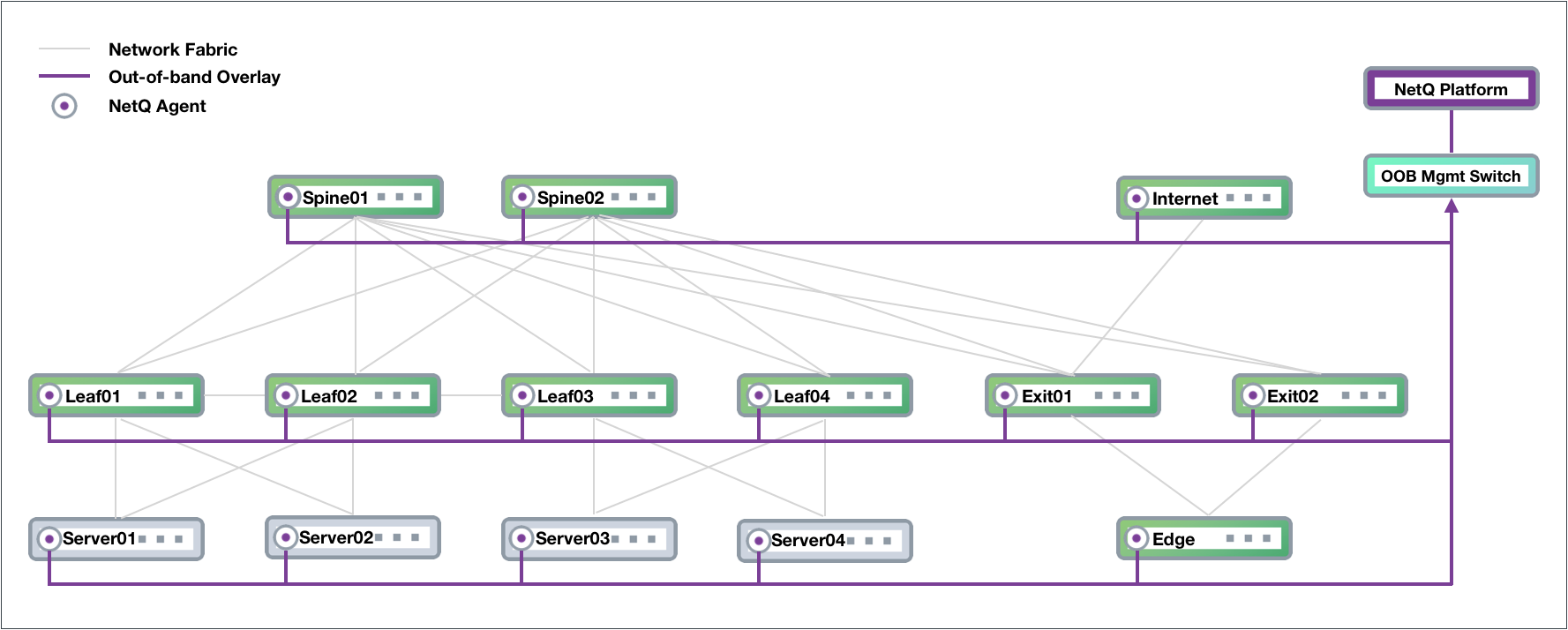
Out-of-band Management Deployment
NVIDIA recommends deploying NetQ on an out-of-band (OOB) management network to separate network management traffic from standard network data traffic, but does not require it. This figure shows a sample Clos-based network fabric design for a data center using an OOB management network overlaid on top, where NetQ resides.
The physical network hardware includes:
- Spine switches: aggregate and distribute data; also known as an aggregation switch, end-of-row (EOR) switch or distribution switch
- Leaf switches: where servers connect to the network; also known as a Top of Rack (TOR) or access switch
- Server hosts: host applications and data served to the user through the network
- Exit switch: where connections to outside the data center occur; also known as Border Leaf or Service Leaf
- Edge server (optional): where the firewall is the demarcation point, peering can occur through the exit switch layer to Internet (PE) devices
- Internet device (PE): where provider edge (PE) equipment communicates at layer 3 with the network fabric
The diagram shows physical connections (in the form of grey lines) between Spine 01 and four Leaf devices and two Exit devices, and Spine 02 and the same four Leaf devices and two Exit devices. Leaf 01 and Leaf 02 connect to each other over a peerlink and act as an MLAG pair for Server 01 and Server 02. Leaf 03 and Leaf 04 connect to each other over a peerlink and act as an MLAG pair for Server 03 and Server 04. The Edge connects to both Exit devices, and the Internet node connects to Exit 01.
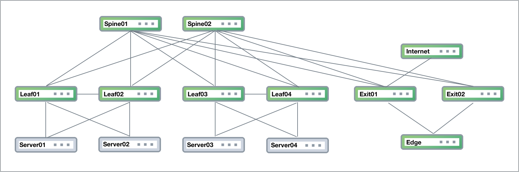
Data Center Network Example
The physical management hardware includes:
- OOB Management Switch: aggregation switch that connects to all network devices through communications with the NetQ Agent on each node
- NetQ Platform: hosts the telemetry software, database and user interfaces (refer to description above)
These switches connect to each physical network device through a virtual network overlay, shown with purple lines.
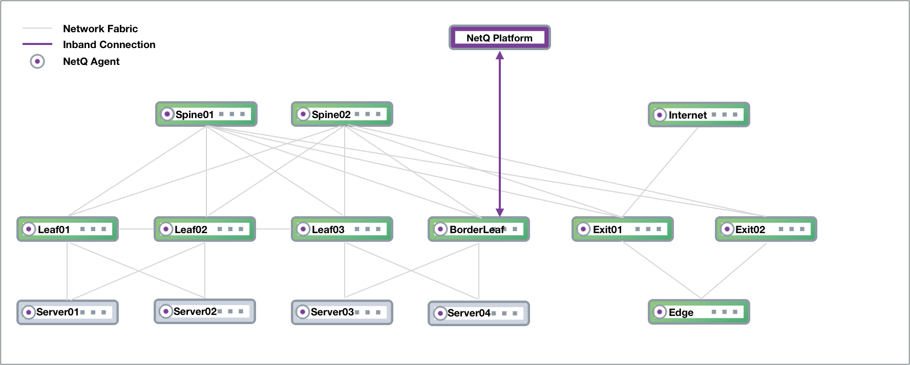
In-band Management Deployment
While not the preferred deployment method, you might choose to implement NetQ within your data network. In this scenario, there is no overlay and all traffic to and from the NetQ Agents and the NetQ Platform traverses the data paths along with your regular network traffic. The roles of the switches in the Clos network are the same, except that the NetQ Platform performs the aggregation function that the OOB management switch performed. If your network goes down, you might not have access to the NetQ Platform for troubleshooting.
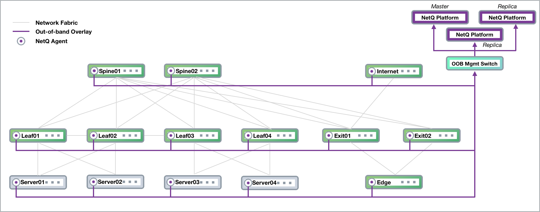
High Availability Deployment
NetQ supports a high availability deployment for users who prefer a solution in which the collected data and processing provided by the NetQ Platform remains available through alternate equipment should the platform fail for any reason. In this configuration, three NetQ Platforms are deployed, with one as the master and two as workers (or replicas). Data from the NetQ Agents is sent to all three switches so that if the master NetQ Platform fails, one of the replicas automatically becomes the master and continues to store and provide the telemetry data. This example is based on an OOB management configuration, and modified to support high availability for NetQ.