Manage Switch Configurations
You can use the NetQ UI to configure switches using one or more switch configurations. To enable consistent application of configurations, switch configurations can contain network templates for SNMP, NTP, and user accounts, VLAN and MLAG settings, and configuration profiles for interfaces and NetQ Agents.
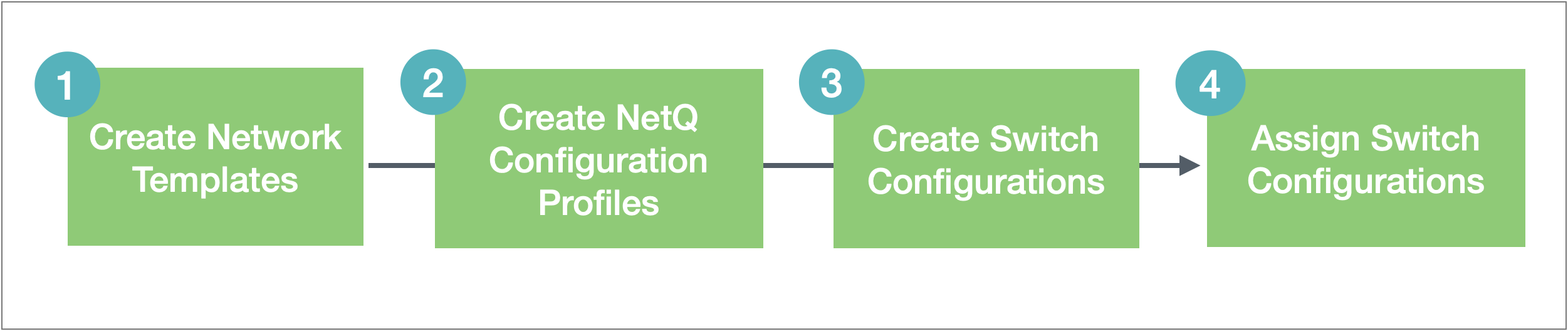
If you intend to use network templates or configuration profiles, the recommended workflow is as follows:
If you do not want to use the templates or profiles, simply skip to switch configuration.
Manage Network Templates
Network templates provide administrators the option to create switch configuration profiles that can be applied to multiple switches. They can help reduce inconsistencies with switch configuration and speed the process of initial configuration and upgrades. No default templates are provided.
View Network Templates
You can view existing templates using the Network Templates card.
Open the lifecycle management (Manage Switch Assets) dashboard.
Click Configuration Management.
Locate the Network Templates card.
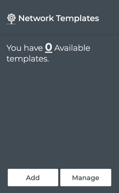
Click Manage to view the list of existing switch templates.
Create Network Templates
No default templates are provided on installation of NetQ. This enables you to create configurations that match your specifications.
To create a network template:
Open the lifecycle management (Manage Switch Assets) dashboard.
Click Configuration Management.
Click Add on the Network Templates card.
Decide which aspects of configuration you want included in this template: SNMP, NTP, LLDP, and/or User accounts.
You can specify your template in any order, but to complete the configuration, you must open the User form to click Save and Finish.
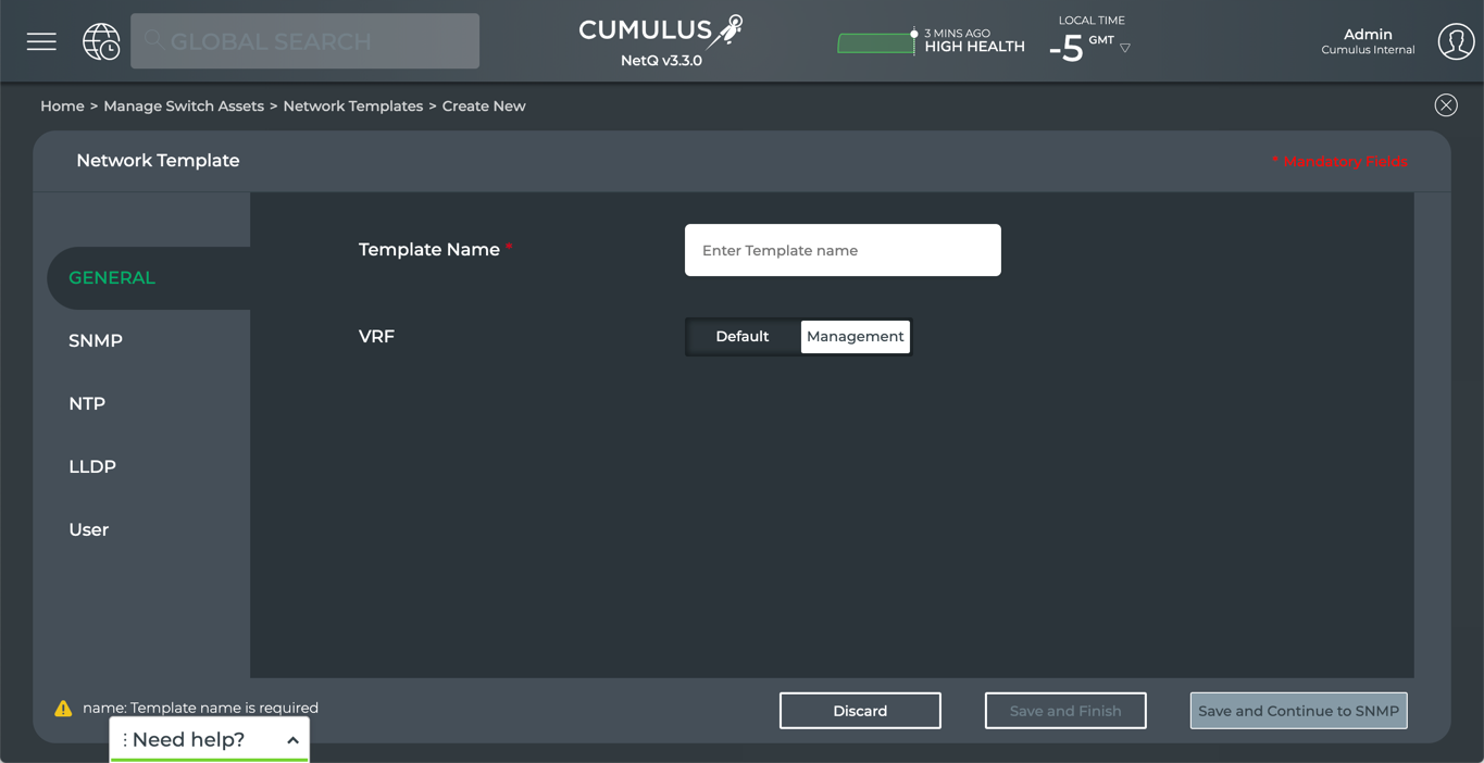
Configure the template using the following instructions.
Provide a name for the template. You must provide a name, which can have a maximum of 22 characters, including spaces.
Accept the VRF selection of Management, or optionally change it to Default. Note that changing the VRF might cause some agents to become unresponsive.
Click Save and Continue to SNMP or select another tab.
SNMP provides a way to query, monitor, and manage your devices in addition to NetQ.
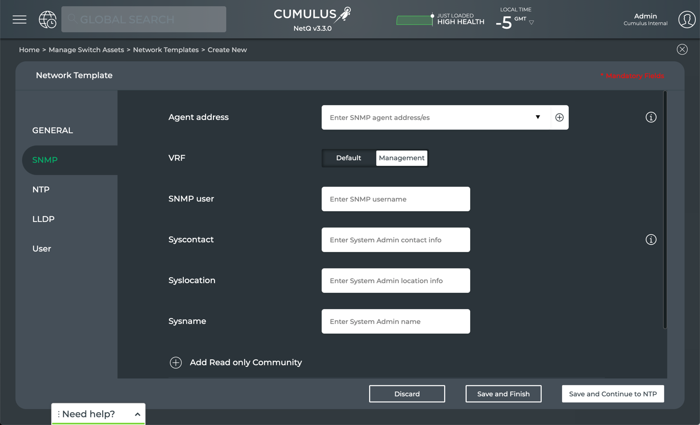
To create a network template with SNMP parameters included:
Enter the IP addresses of the SNMP Agents on the switches and hosts in your network.
You can enter individual IP addresses, a range of IP addresses, or select from the address categories provided (click
 ).
).After adding one of these, you can create another set of addresses by clicking
 . Continue until you have entered all desired SNMP agent addresses.
Accept the management VRF or change to the default VRF.
Enter the SNMP username(s) of persons who have access to the SNMP server.
Enter contact information for the SNMP system administrator, including an email address or phone number, their location, and name.
Restrict the hosts that should accept SNMP packets:
Click
next to Add Read only Community.
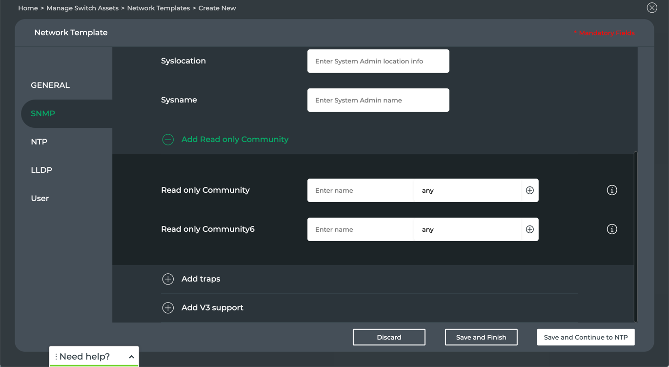
- Enter the name of an IPv4 or IPv6 community string.
- Indicate which hosts should accept messages:
Accept any to indicate all hosts are to accept messages (default), or enter the hostnames or IP addresses of the specific hosts that should accept messages. - Click to add additional community strings.
Specify traps to be included:
Click
next to Add traps.
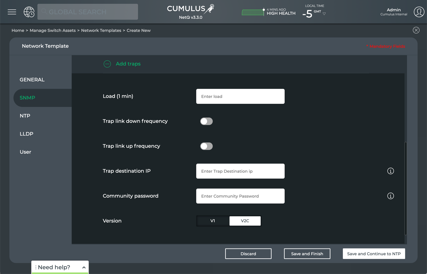
- Specify the traps as follows:
Parameter Description Load (1 min) Threshold CPU load must cross within a minute to trigger a trap Trap link down frequency Toggle on to set the frequency at which to collect link down trap information. Default value is 60 seconds. Trap link up frequency Toggle on to set the frequency at which to collect link up trap information. Default value is 60 seconds. IQuery Secname Security name for SNMP query Trap Destination IP IPv4 or IPv6 address where the trap information is to be sent. This can be a local host or other valid location. Community Password Authorization password. Any valid string, where an exclamation mark (!) is the only allowed special character. Version SNMP version to use
If you are using SNMP version 3, specify relevant V3 support parameters:
Click
next to Add V3 support.
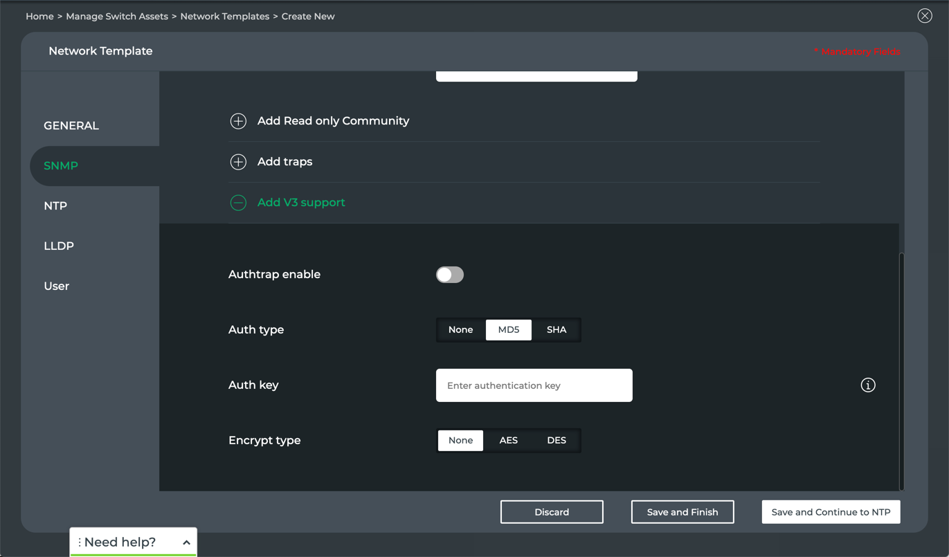
- Toggle Authtrap enable to configure authentication for users accessing the SNMP server.
- Select an authorization type.
For either MDS or SHA, enter an authorization key and optionally specify AES or DES encryption.
- Click Save and Continue to NTP or select another tab.
Switches and hosts must be kept in time synchronization with the NetQ appliance or VM to ensure accurate data reporting. NTP is one protocol that can be used to synchronize the clocks of these devices. None of the parameters are required. Specify those which apply to your configuration.
To create a network template with NTP parameters included:
- Click NTP.
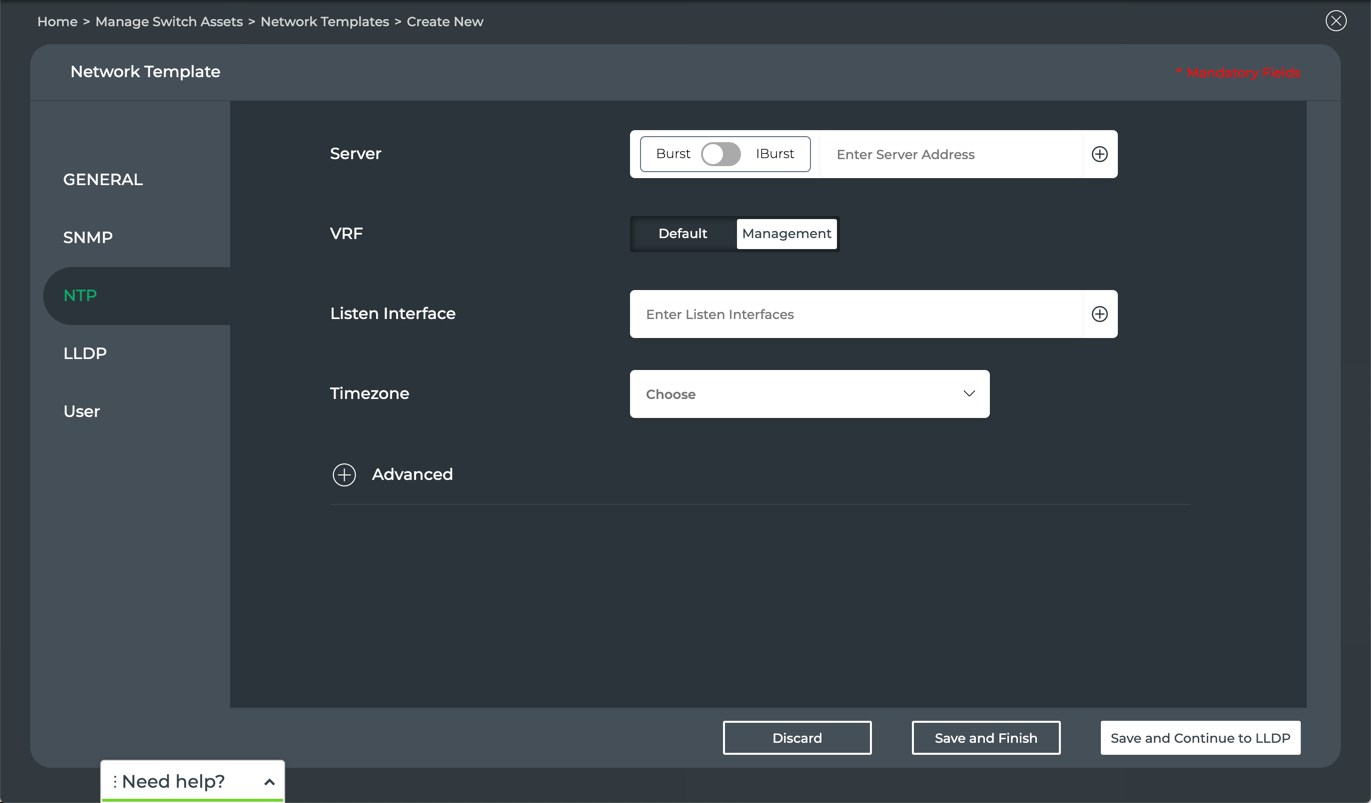
Enter the address of one or more of your NTP servers. Toggle to choose between Burst and IBurst to specify whether the server should send a burst of packets when the server is reachable or unreachable, respectively.
Specify either the Default or Management VRF for communication with the NTP server.
Enter the interfaces that the NTP server should listen to for synchronization. This can be a IP, broadcast, manycastclient, or reference clock address.
Select the timezone of the NTP server.
Specify advanced parameters:
Click
next to Advanced.
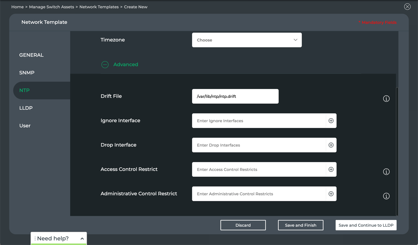
- Specify the location of a Drift file containing the frequency offset between the NTP server clock and the UTC clock. It is used to adjust the system clock frequency on every system or service start. Be sure that the location you enter can be written by the NTP daemon.
- Enter an interface for the NTP server to ignore. Click to add more interfaces to be ignored.
- Enter one or more interfaces from which the NTP server should drop all messages. Click to add more interfaces to be dropped.
- Restrict query and configuration access to the NTP server.
For each restriction, enter restrict followed by the value. Common values include:
ClickValue Description default Block all queries except as explicitly indicated kod (kiss-o-death) block all, but time and statistics queries nomodify block changes to NTP configuration notrap block control message protocol traps nopeer block the creation of a peer noquery block NTP daemon queries, but allow time queries to add more access control restrictions. - Restrict administrative control (host) access to the NTP server.
Enter the IP address for a host or set of hosts, with or without a mask, followed by a restriction value (as described in step 5.) If no mask is provided, 255.255.255.255 is used. If *default* is specified for query/configuration access, entering the IP address and mask for a host or set of hosts in this field allows query access for these hosts (explicit indication).
Click to add more administrative control restrictions.
- Click Save and Continue to LLDP or select another tab.
LLDP advertises device identities, capabilities, and neighbors. The network template enables you to specify how often you want the advertisement to take place and how long those messages should remain alive on the network.
To create a network template with LLDP parameters included:
- Click LLDP.
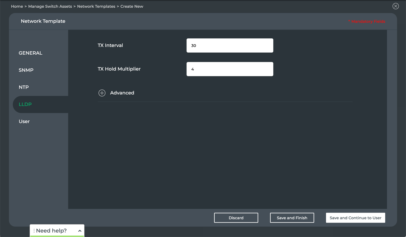
Enter the interval, in seconds, that you want LLDP to transmit neighbor information and statistics.
Enter how many times the transmit interval you want for LLDP messages to live on the network.
Optionally, specify advanced features by clicking
next to Advanced.
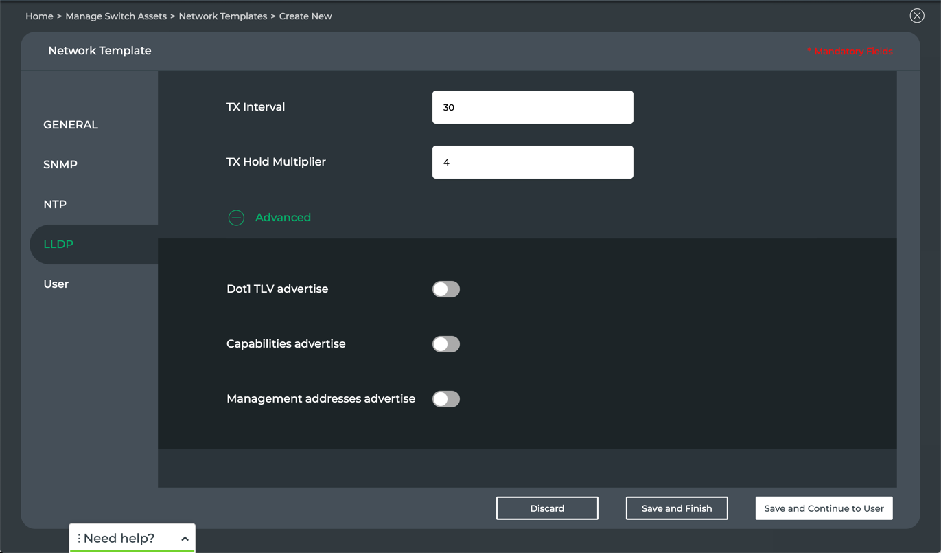
- Enable advertisement of IEEE 802.1Q TLV (type-length-value) structures, including port description, system name, description and capabilities, management address, and custom names. Mandatory TLVs include end of LLDPPDU, chassis ID, port ID, and time-to-live.
- Enable advertisement of system capability codes for the nodes. For example:
Code Capability B Bridge (Switch) C DOCSIS Cable Device O Other P Repeater R Router S Station T Telephone W WLAN Access Point - Enable advertisement of the IP address used for management of the nodes.
- Click Save and Continue to User or select another tab.
Creating a User template controls who or what accounts can access the switch and what permissions they have with respect to the data found (read/write/execute). You can also control access using groups of users. No parameters are required. Specify parameters which apply to your specific configuration need.
To create a network template with user parameters included:
- Click User.
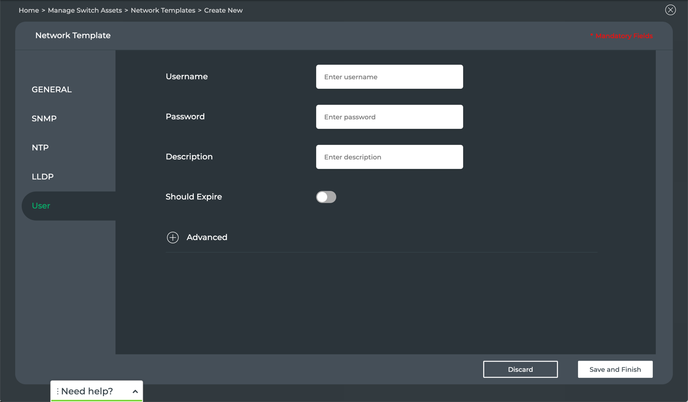
Enter the username and password for one or more users.
Provide a description of the users.
Toggle Should Expire to set the password to expire on a given date.
The current date and time are automatically provided. Click in the field to modify this to the appropriate expiration date.
Specify advanced parameters:
Click
next to Advanced.
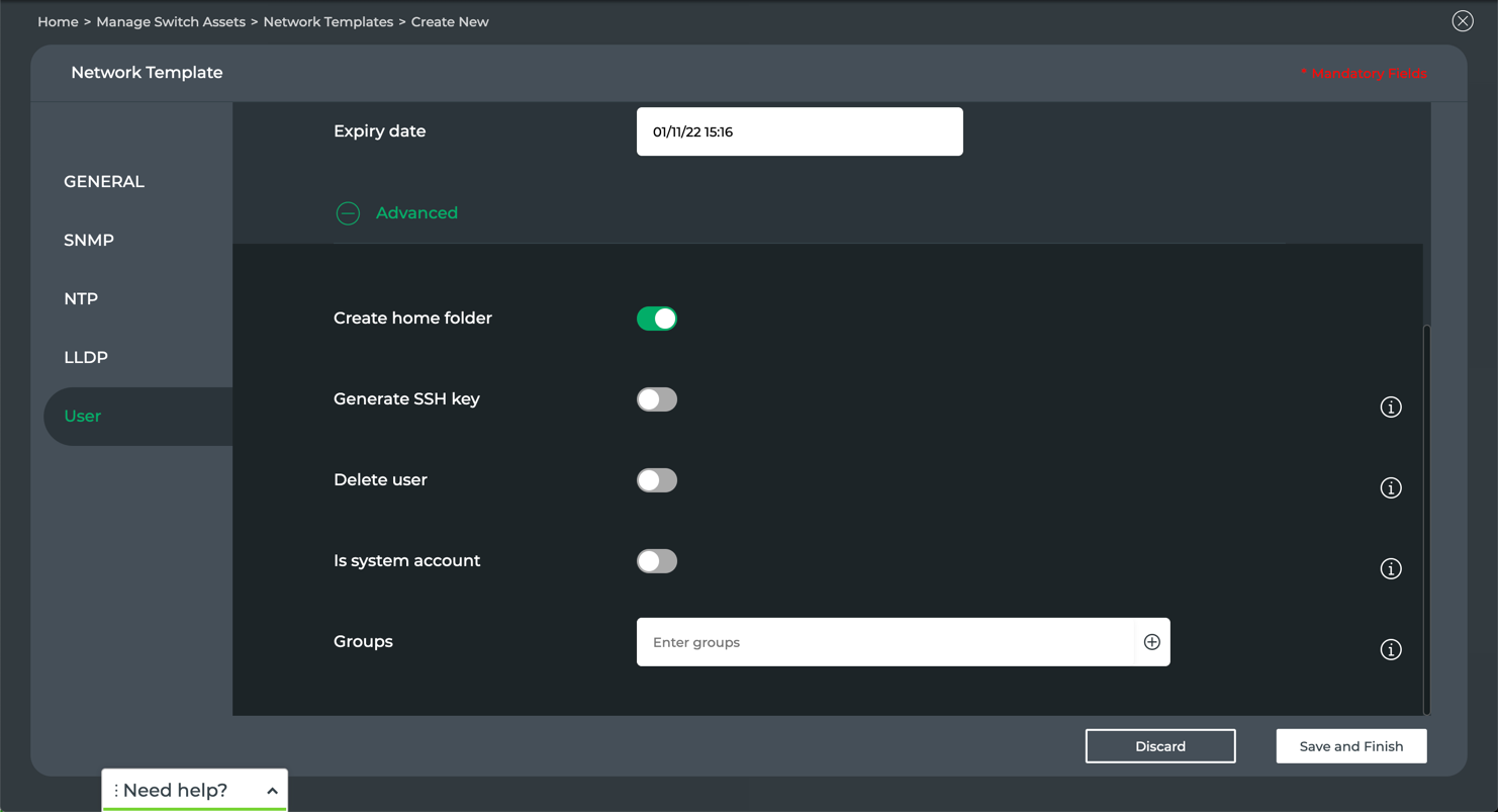
- If you do not want a home folder created for this user or account, toggle Create home folder.
- Generate an SSH key pair for this user(s). Toggle Generate SSH key. When generation is selected, the key pair is stored in the /home/<user>/.ssh directory.
- If you are looking to remove access for the user or account, toggle Delete user. If you do not want to remove the directories associated with this user or account at the same time, leave toggle as is (default, do not delete).
- Identify this account as a system account. Toggle Is system account. System users have no expiration date assigned. Their IDs are selected from the SYS_UID_MIN-SYS_UID_MAX range.
- To specify additional access groups these users belongs to, enter the group names in the Groups field.
Click to add additional groups.
- Click Save and Finish.
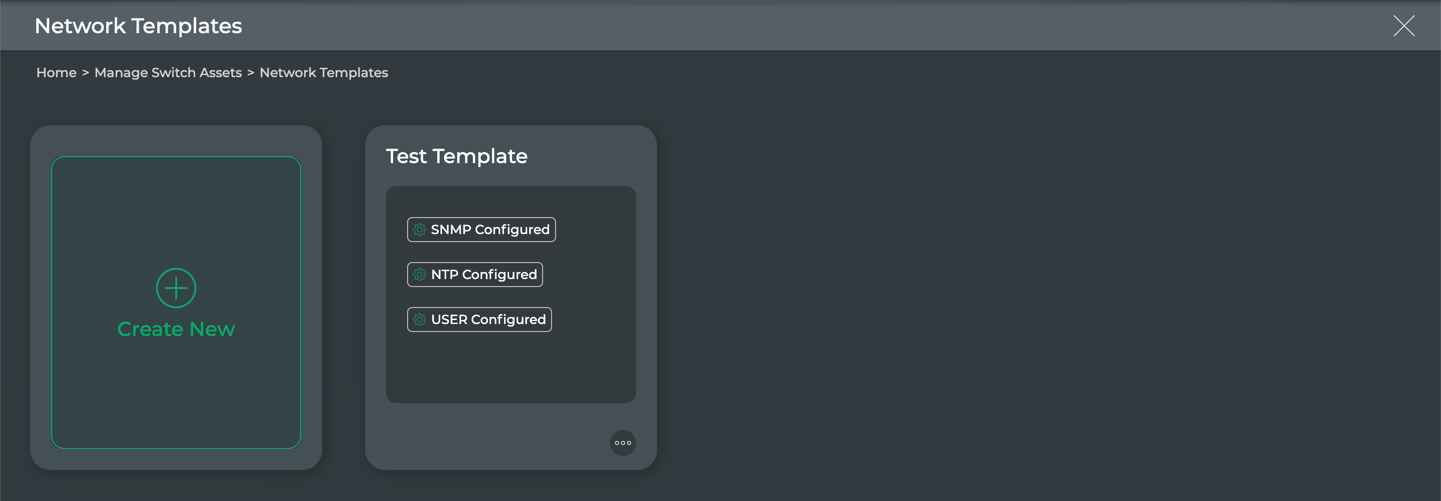
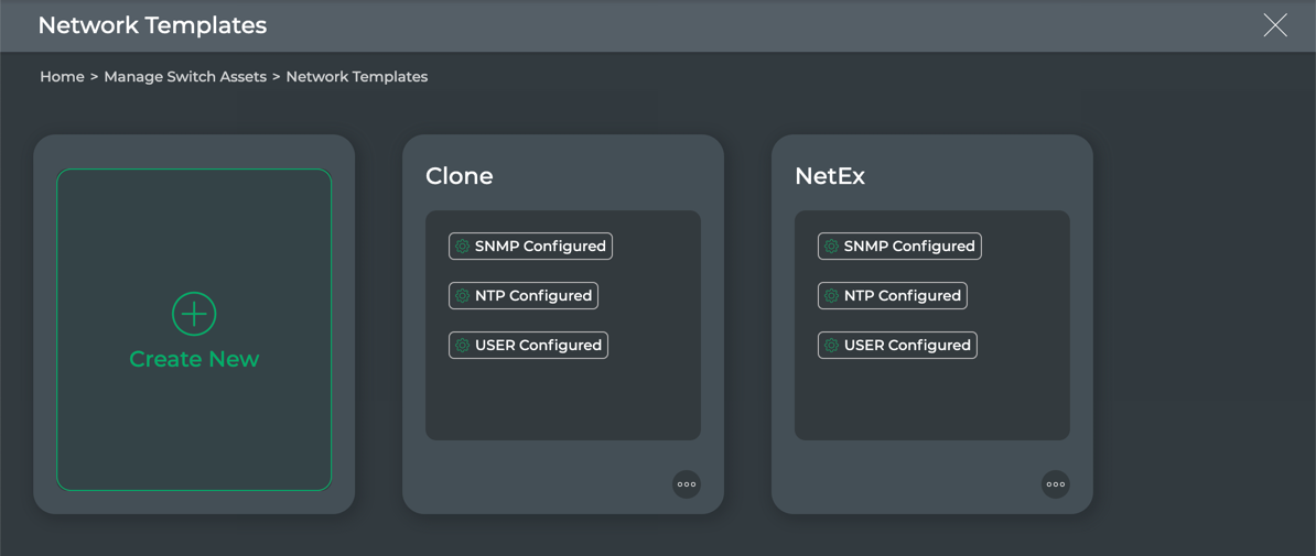
Once you have finished the template configuration, you are returned to the network templates library.
This shows the new template you created and which forms have been included in the template. You might only have one or two of the forms in a given template.
Modify Network Templates
For each template that you have created, you can edit, clone, or discard it altogether.
Edit a Network Template
You can change a switch configuration template at any time. The process is similar to creating the template.
To edit a network template:
Enter template edit mode in one of two ways:
Hover over the template , then click
 (edit).
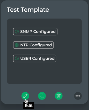
Click
 , then select Edit.
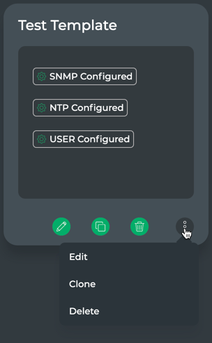
Modify the parameters of the various forms in the same manner as when you created the template.
Click User, then Save and Finish.
Clone a Network Template
You can take advantage of a template that is significantly similar to another template that you want to create by cloning an existing template. This can save significant time and reduce errors.
To clone a network template:
Enter template clone mode in one of two ways:
Hover over the template , then click
 (clone).
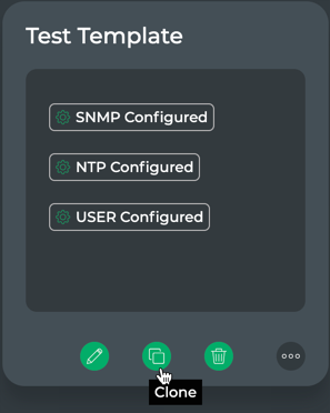
Click
, then select Clone.
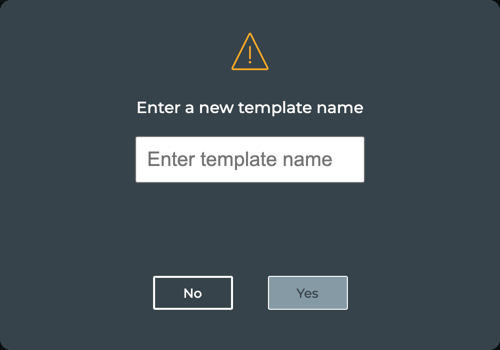
Enter a new name for this cloned template and click Yes. Or to discard the clone, click No.
Modify the parameters of the various forms in the same manner as when you created the template to create the new template.
Click User, then Save and Finish.
The newly cloned template is now visible on the template library.
Delete a Network Template
You can remove a template when it is no longer needed.
To delete a network template, do one of the following:
Hover over the template , then click
(delete).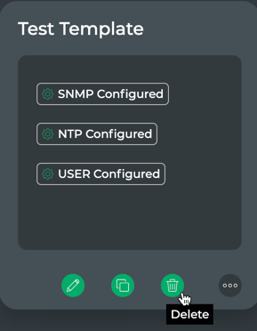
Click
, then select Delete.
The template is no longer visible in the network templates library.
Manage NetQ Configuration Profiles
You can set up a configuration profile to indicate how you want NetQ configured when it is installed or upgraded on your Cumulus Linux switches.
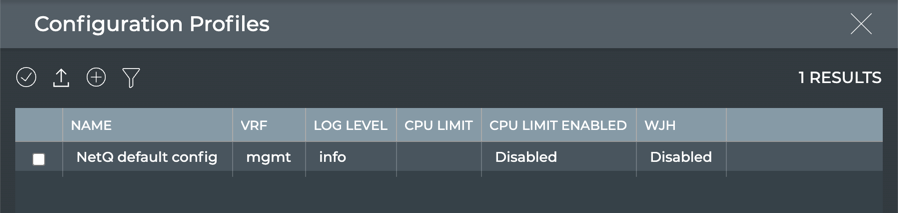
The default configuration profile, NetQ default config, is set up to run in the management VRF and provide info level logging. Both WJH and CPU Limiting are disabled.
You can view, add, and remove NetQ configuration profiles at any time.
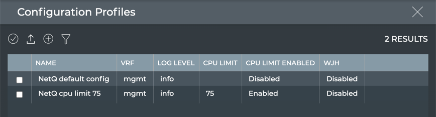
View NetQ Configuration Profiles
To view existing profiles:
Click
 (Switches) in the workbench header, then click Manage switches, or click
  (Main Menu) and select Manage Switches.
Click Configuration Management.
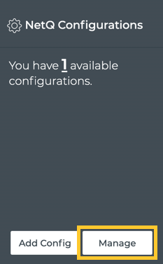
Click Manage on the NetQ Configurations card.
Note that the initial value on first installation of NetQ shows one profile. This is the default profile provided with NetQ.
- Review the profiles.
Run the netq lcm show netq-config command:
cumulus@switch:~$ netq lcm show netq-config
ID                        Name            Default Profile                VRF             WJH       CPU Limit Log Level Last Changed
------------------------- --------------- ------------------------------ --------------- --------- --------- --------- -------------------------
config_profile_3289efda36 NetQ default co Yes                            mgmt            Disable   Disable   info      Tue Jan  5 05:25:31 2021
db4065d56f91ebbd34a523b45 nfig
944fbfd10c5d75f9134d42023
eb2b
config_profile_233c151302 CPU limit 75%   No                             mgmt            Disable   75%       info      Mon Jan 11 19:11:35 2021
eb8ee77d6c27fe2eaca51a9bf
2dfcbfd77d11ff0af92b807de
a0dd
Create NetQ Configuration Profiles
You can specify four options when creating NetQ configuration profiles:
- Basic: Assign a VRF, and enable or disable what just happened (WJH) feature
- Advanced: Set logging level, and enable or disable CPU limit feature
To create a profile:
Click
(Switches) in the workbench header, then click Manage switches, or click (Main Menu) and select Manage Switches.Click Configuration Management.
Click Manage on the NetQ Configurations card.
Click
(Add Config) above the listing.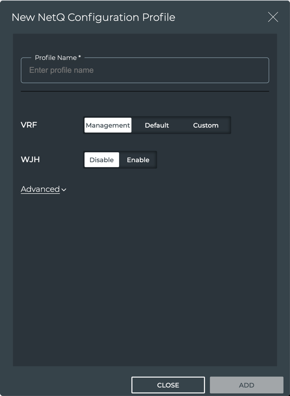
Enter a name for the profile. This is required.
If you do not want NetQ Agent to run in the management VRF, select either Default or Custom. The Custom option lets you enter the name of a user-defined VRF.
Optionally enable WJH.
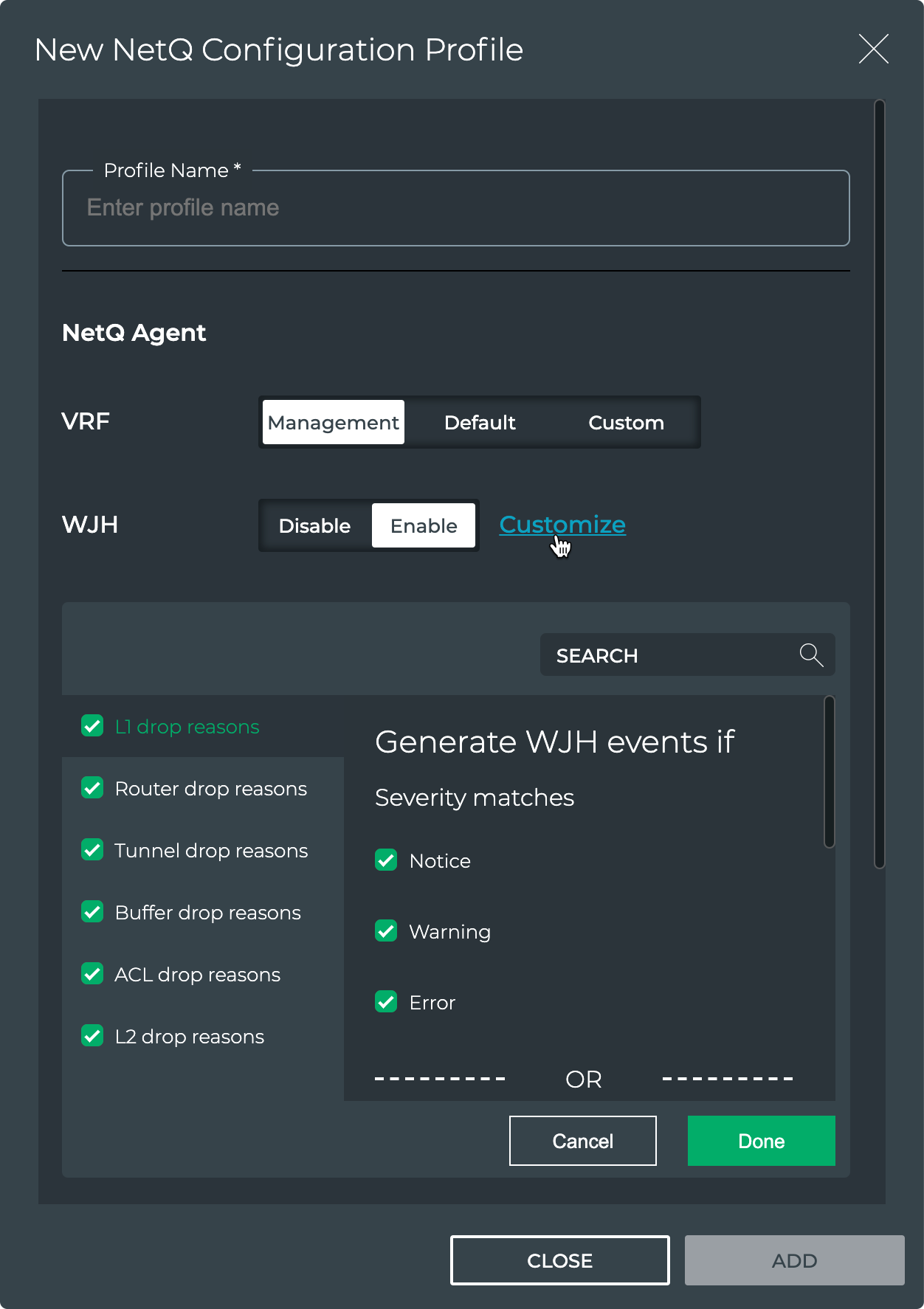
Refer to What Just Happened for information about configuring this feature, and to WJH Event Messages Reference for a description of the drop reasons. WJH is only available on Mellanox switches.
If you choose to enable WJH for this profile, you can use the default configuration which collects all statistics, or you can select Customize to select which categories and drop reasons you want collected. This is an Early Access capability. Click on each category and drop reason you do not want collected, then click Done. You can discard your changes (return to all categories and drop reasons) by clicking Cancel.
To set a logging level, click Advanced, then choose the desired level.
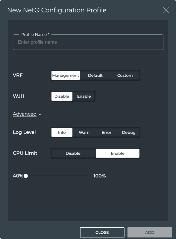
Optionally set a CPU usage limit for the NetQ Agent. Click Enable and drag the dot to the desired limit.
Refer to this Knowledge Base article for information about this feature.
Click Add to complete the configuration or Close to discard the configuration.
This example shows the addition of a profile with the CPU limit set to 75 percent.
Remove NetQ Configuration Profiles
To remove a NetQ configuration profile:
Click
(Switches) in the workbench header, then click Manage switches, or click (Main Menu) and select Manage Switches.Click Configuration Management.
Click Manage on the NetQ Configurations card.
Select the profile(s) you want to remove and click
 (Delete).
Manage Switch Configuration
To ease the consistent configuration of your switches, NetQ enables you to create and manage multiple switch configuration profiles. Each configuration can contain Cumulus Linux, NetQ Agent, and switch settings. These can then be applied to a group of switches at once.
You can view, create, and modify switch configuration profiles and their assignments at any time using the Switch Configurations card.
New switch configuration features introduced with release 3.3.0 are Early Access features and are provided in advance of general availability to enable customers to try them out and provide feedback. These features are bundled into the netq-apps package so there is no need to install a separate software package. The features are enabled by default and marked in the documentation here as Early Access.
View Switch Configuration Profiles
You can view existing switch configuration profiles using the Switch Configurations card.
Open the lifecycle management (Manage Switch Assets) dashboard.
Click
, then select Manage Switches. Alternately, click  in a workbench header.
Click Configuration Management.
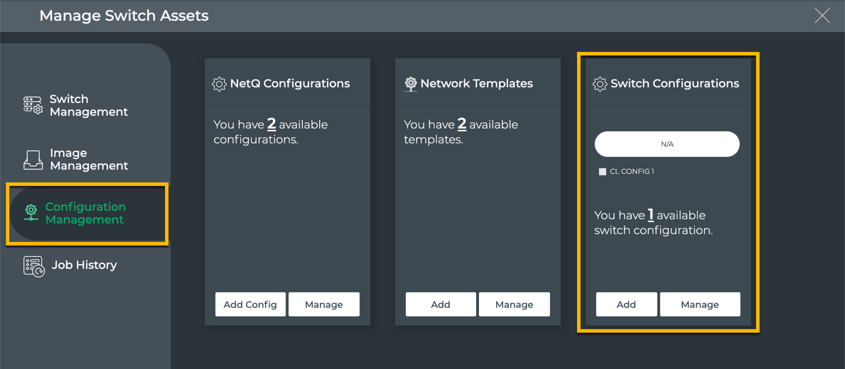
Locate the Switch Configurations card.
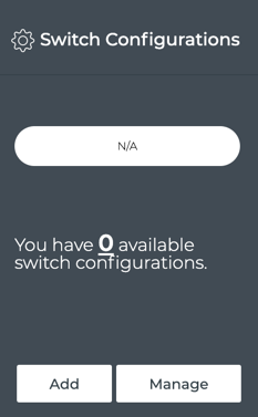
Click Manage to view the list of existing switch templates.
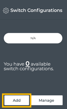
Create Switch Configuration Profiles
No default configurations are provided on installation of NetQ. This enables you to create configurations that match your specifications.
To create a switch configuration profile:
Open the lifecycle management (Manage Switch Assets) dashboard.
Click Configuration Management.
Click Add on the Switch Configurations card.
You must begin with the Cumulus Linux option. Then you can decide which other aspects of configuration you want included in this template: NetQ Agent, VLANs, MLAG, and/or interfaces.
Specify the settings for each using the following instructions.
The VLAN, MLAG, Interface profiles and Interfaces settings are provided as Early Access capabilities.
Four configuration items are available for the Cumulus Linux configuration portion of the switch configuration profile. Items with a red asterisk (*) are required.
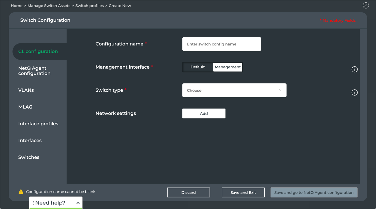
Enter a name for the configuration. The name can be a maximum of 22 characters, including spaces.
Enter the management interface (VLAN ID) to be used for communications with the switches with this profile assigned. Commonly this is either eth0 or eth1.
Select the type of switch that will have this configuration assigned from the Switch type dropdown. Currently this includes Mellanox SN series of switches.
Choose carefully as once this has been selected, it cannot be changed for the given switch configuration profile. You must create a new profile.
If you want to include network settings in this configuration, click Add.
This opens the Network Template forms. You can select an existing network template to pre-populate the parameters already specified in that template, or you can start from scratch to create a different set of network settings.
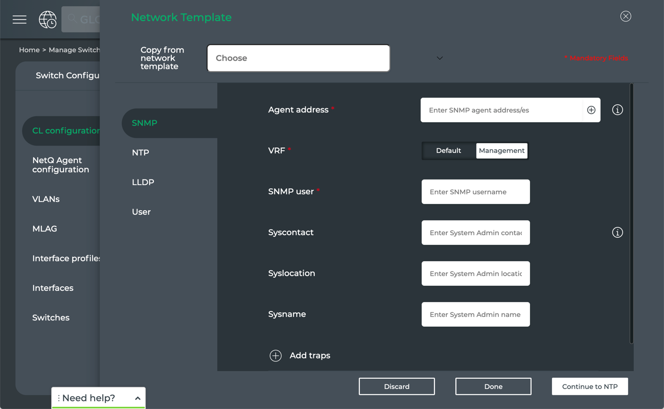 To use an existing network template as a starting point:
Select the template from the dropdown.
If you have selected a network template that has any SNMP parameters specified, verify those parameters and specify any additional required parameters, then click Continue or click NTP.
If the selected network template has any NTP parameters specified, verify those parameters and specify any additional required parameters, then click Continue or click LLDP.
If the selected network template has any LLDP parameters specified, verify those parameters, then click Continue or click User.
If the selected network template has any User parameters specified, verify those parameters and specify any additional required parameters, then click Done.
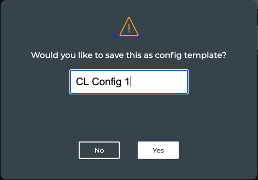
If you think this Cumulus Linux configuration is one that you will use regularly, you can make it a template. Enter a name for the configuration and click Yes.
 To create a new set of network settings:
Select the various forms to specify parameters for this configuration. Note that selected parameters are required on each form, noted by red asterisks (*). Refer to Create Network Templates for a description of the fields.
When you have completed the network settings, click Done.
If you are not on the User form, you need to go to that tab for the Done option to appear.
In either case, if you change your mind about including network settings, click
 to exit the form.
- Click one of the following:
- Discard to clear your entries and start again
- Save and go to NetQ Agent configuration to configure additional switch configuration parameters
- Save and deploy on switches if the switch configuration is now complete
- Click NetQ Agent Configuration.
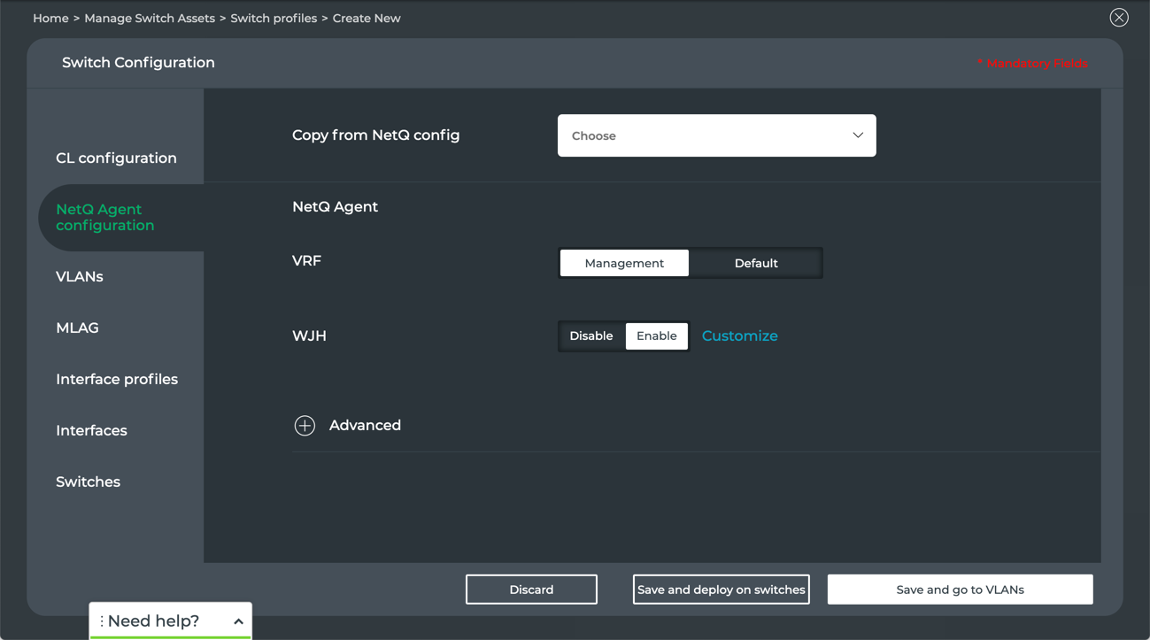
Select an existing NetQ Configuration profile or create a custom one.
To use an existing network template as a starting point:
- Select the configuration profile from the dropdown.
- Modify any of the parameters as needed.
To create a new configuration profile:
- Select values as appropriate for your situation. Refer to Create NetQ Configuration Profiles for descriptions of these parameters.
- Click one of the following:
- Discard to clear your entries and start again
- Save and go to VLANs to configure additional switch configuration parameters
- Save and deploy on switches if the switch configuration is now complete
This is an Early Access capability.
Click VLANs.
Click Add VLAN/s if none are present, or click
to add more VLANs to the switch configuration.
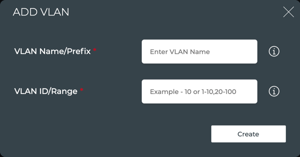
Enter a name for the VLAN when creating a single VLAN or enter a prefix (combined with the VLAN ID) for multiple VLANs.
Enter a single VLAN ID (1-4096) or a range of IDs. When entering multiple IDs, separate them by commas and do not use spaces. For example, you can enter them:
- One at a time: 25,26,27,28,85,86,87,88,89,112
- As a set of ranges and individual IDs: 25-28,85-89 or 25-28,85-89,112
- As a single range: 25-28 or 85-89
Click Create.
The VLAN/s are displayed in the VLAN list. Once VLANs are in the list, they can be exported, modified, removed, and duplicated using the menu above the list. Simply select one, all, or filter for a subset of VLANs, then click the relevant menu icon.
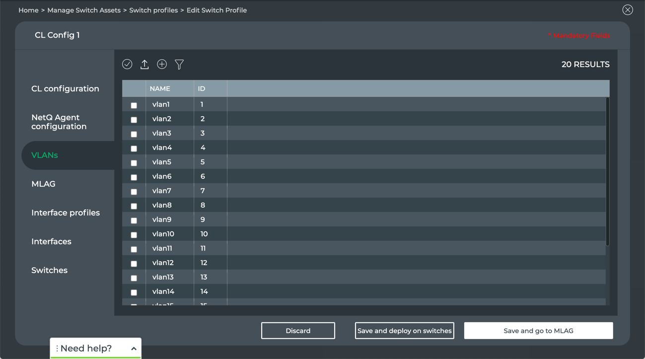
- Click one of the following:
- Discard to clear your entries and start again
- Save and go to MLAG to configure additional switch configuration parameters
- Save and deploy on switches if the switch configuration is now complete
MLAG is disabled by default. If you want to include MLAG in the switch configuration, you must enable it.
- Click Enable.
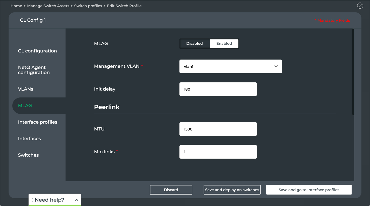
Select the VLAN over which MLAG traffic is communicated. If you have created VLANs already, select the VLAN from the Management VLAN dropdown. If you have not yet created any VLANs, refer to VLAN tab and then return here.
Accept the default (180 seconds) or modify the amount of time
clagdshould wait to bring up the MLAG bonds and anycast IP addresses.Specify the peerlink. Note items with a red asterisk (*) are required.
- Enter the supported MTU for this link
- Enter the minimum number of links to use. Add additional links to handle link failures of the peerlink bond itself.
- Select the private VLAN (PVID) from the dropdown. If you have not yet created any VLANs, refer to VLAN tab and then return here.
- Enter a tagged VLAN range to link switches.
- Designate which ports are to be used, including ingress and egress ports.
- Click one of the following:
- Discard to clear your entries and start again
- Save and go to Interface profiles to configure additional switch configuration parameters
- Save and deploy on switches if the switch configuration is now complete
This is an Early Access capability.
Every interface requires at least one interface profile. Specifically, a bond, SVI, sub-interface, or port interface require at least one corresponding interface profile. For example, for a given bond interface, you must have at least one bond interface profile. For a given SVI, you must have at least one SVI interface profile. And so forth. Each of these can be configured independently. That is, configuring a bond interface and interface profile does not require you to configure any of the other SVI, sub-interface or port interface options.
Interface profiles are used to speed configuration of switches by configuring common capabilities of an interface component and then referencing that profile in the component specification.
Add Bond Profiles
You can create a new bond profile or import an existing one to modify. Bond profiles are used to specify interfaces in the switch configuration.
To create a new bond profile:
Click Interface profiles.
Click Create if no profiles yet exist, or click
to add another bond profile.
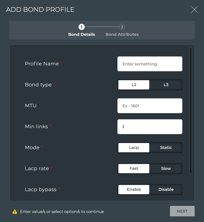
Enter a unique name for the bond profile. Note that items with a red asterisk (*) are required.
Click on the type of bond this profile is to support; either layer 2 (L2) or layer 3 (L3).
Enter the supported MTU for this bond profile.
Enter the minimum number of links to use. Add additional links to handle link failures of the bond itself.
Select the mode this profile is to support: either Lacp or Static.
Choosing Lacp (link aggregation control protocol) allows for redundancy by load-balancing traffic across all available links. Choosing Static provides no load balancing.
If you select LACP, then you must also specify:
- The LACP rate: how often to expect PDUs at the switch; Fast–every second, or Slow–every 30 seconds
- Whether to enable or disable LACP bypass: Enable allows a bond configured in 802.3ad mode to become active and forward traffic even when there is no LACP partner
Enable or disable whether the bond must be dually connected. When enabled, you must specify the associated MLAG identifier.
Click Next to specify the bond attributes.
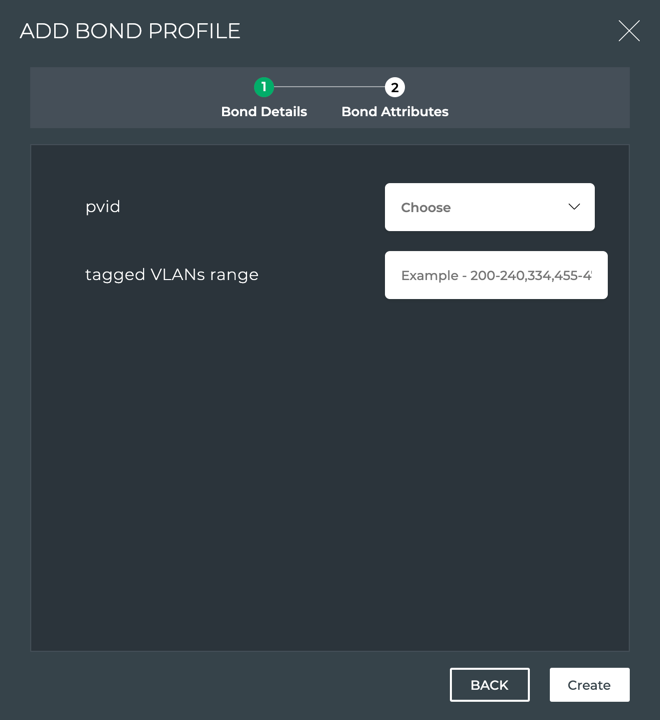
Select a private VLAN ID (pvid) from the dropdown for communication.
Assign one or more tagged VLANs to support traffic from more than one VLAN on a port.
Review your specification, clicking Back to review the bond details.
When you are satisfied with the bond profile specification, click Create.
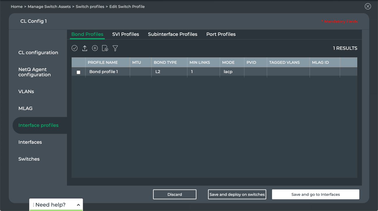
The bond profiles are displayed in the Bond list. Once bonds are in the list, they can be exported, modified, removed, and duplicated using the menu above the list. Simply select one, all, or filter for a subset of bonds, then click the relevant menu icon.
To import an existing bond profile:
Click Interface profiles.
Click Import if no profiles yet exist, or click
 to import a bond profile.
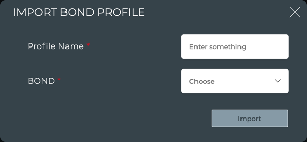
Enter a name for this new bond profile.
Select a bond from the dropdown.
Click Import.
Select the profile from the list and click
to edit it.
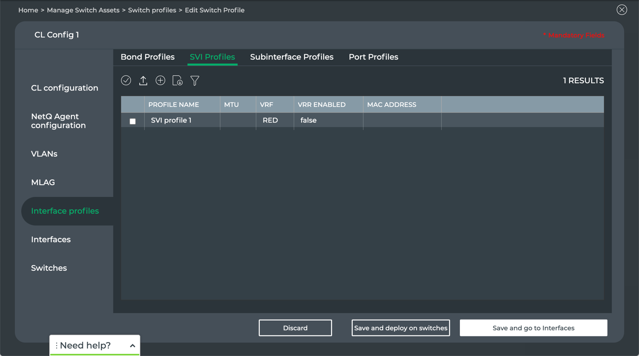
Add SVI Profiles
You can create a new SVI profile or import an existing one to modify. SVI profiles are used to specify interfaces in the switch configuration.
To create a new SVI profile:
Click Interface profiles.
Click SVI Profiles.
Click Create if no profiles yet exist, or click
to add a new SVI profile.
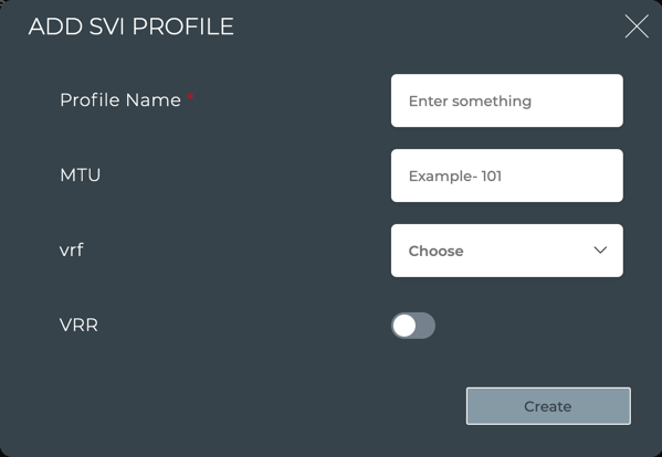
Enter a unique name for the SVI profile.
Enter the supported MTU for this SVI profile.
Select a VRF profile from the dropdown, or enter the name of a VRF and click Add VRF.
Enable VRR if desired, and enter the associated MAC address.
Click Create.
The SVI profiles are displayed in the SVI list. Once SVIs are in the list, they can be exported, modified, removed, and duplicated using the menu above the list. Simply select one, all, or filter for a subset of SVIs, then click the relevant menu icon.
To import an existing SVI profile:
Click Interface profiles.
Click SVI Profiles.
Click Import if no profiles yet exist, or click
to import an SVI profile.
Enter a name for this new SVI profile.
Select an SVI from the dropdown.
Click Import.
Select the profile from the list and click
to edit it.
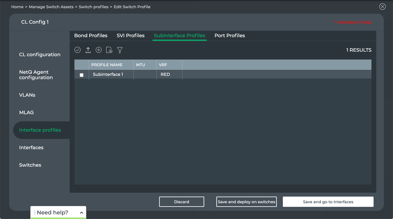
Add Sub-interfaces Profiles
You can create a new subinterface profile or import an existing one to modify. Subinterface profiles are used to specify interfaces in the switch configuration.
Click Interface profiles.
Click Subinterface Profiles.
Click Create if no profiles yet exist, or click
to add a new sub-interface profile.
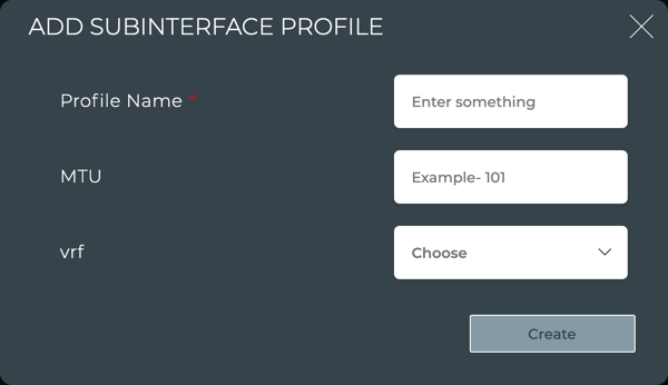
Enter a unique name for the subinterface profile.
Enter the supported MTU for this subinterface profile.
Select a VRF profile from the dropdown, or enter the name of a VRF and click Add VRF.
Click Create.
The subinterface profiles are displayed in the subinterface list. Once subinterfaces are in the list, they can be exported, modified, removed, and duplicated using the menu above the list. Simply select one, all, or filter for a subset of subinterfaces, then click the relevant menu icon.
To import an existing subinterface profile:
Click Interface profiles.
Click Subinterface Profiles.
Click Import if no profiles yet exist, or click
to import a subinterface profile.

Enter a name for this new subinterface profile.
Select a subinterface from the dropdown.
Click Import.
Select the profile from the list and click
to edit it.
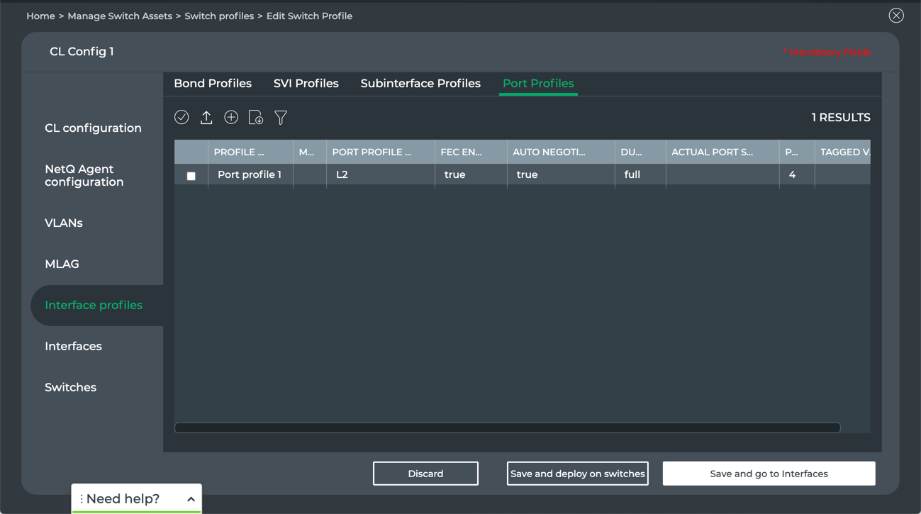
Add Port Profiles
You can create a new port profile or import an existing one to modify. Port profiles are used to specify interfaces in the switch configuration.
Click Interface profiles.
Click Port Profiles.
Click Create if no profiles yet exist, or click
to add a new port profile.
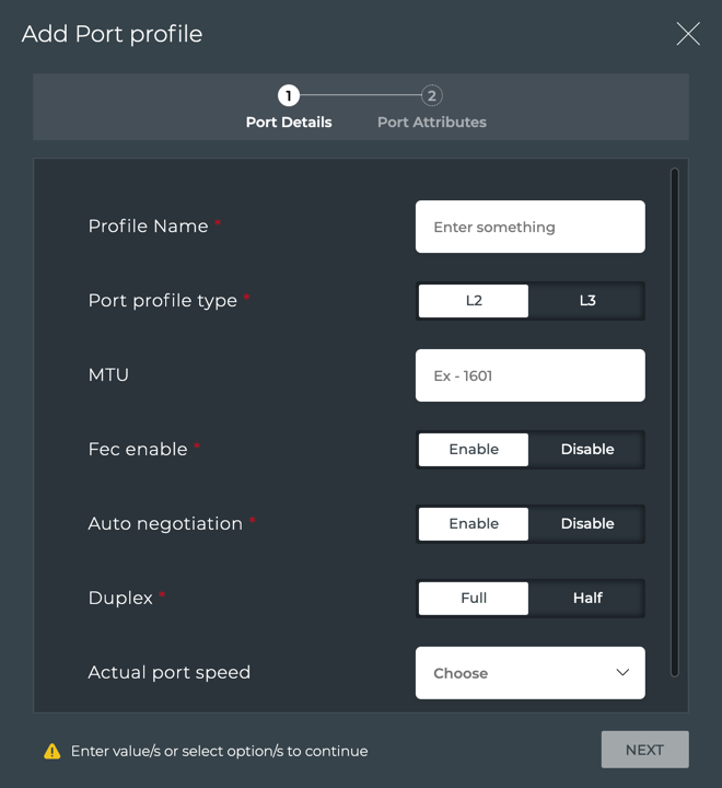
Enter a unique name for the port profile. Note that items with a red asterisk (*) are required.
Click on the type of port this profile is to support; either layer 2 (L2) or layer 3 (L3).
Enter the supported MTU for this port profile.
Enable or disable forward error correction (FEC).
Enable or disable auto-negotiation of link speeds.
Specify the whether to support transmit and receive on this port (Full duplex) or either transmit or receive on this port (Half duplex).
Specify the port speed from the dropdown. Choices are based on the switch type selected iin the CL configuration tab.
Click Next to specify port attributes.

Select a private VLAN ID (pvid) for communication from the dropdown.
Assign one or more tagged VLANs to support traffic from more than one VLAN on a port.
Review your specification, clicking Back to review the bond details.
When you are satisfied with the port profile specification, click Create.
The port profiles are displayed in the Port list. Once ports are in the list, they can be exported, modified, removed, and duplicated using the menu above the list. Simply select one, all, or filter for a subset of ports, then click the relevant menu icon.
To import an existing port profile:
Click Interface profiles.
Click Port Profiles.
Click Import if no profiles yet exist, or click
to import a port profile.
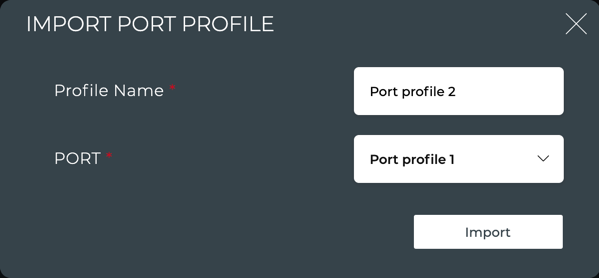
Enter a name for this new port profile.
Select a port profile from the dropdown.
Click Import.
Select the profile from the list and click
to edit it.Now that you have one complete interface profile defined, click one of the following:
- Discard to clear your entries and start again
- Save and go to Interfaces to configure additional switch configuration parameters
- Save and deploy on switches if the switch configuration is now complete
This is an Early Access capability.
Every interface requires at least one interface profile. Specifically, a bond, SVI, sub-interface, or port interface require at least one corresponding interface profile. For example, for a given bond interface, you must have at least one bond interface profile. For a given SVI, you must have at least one SVI interface profile. And so forth. Each of these can be configured independently. That is, configuring a bond interface and interface profile does not require you to configure any of the other SVI, sub-interface or port interface options.
Interfaces identify how and where communication occurs.
Add Bonds
Bonds indicate how switches are connected to each other. You must have at least one bond interface profile specified to configure a bond interface (return to the Interface Profiles tab and see Add Bond Interface Profiles if needed).
Click Interfaces.
Click Create if no bonds exist yet, or click
to add a new bond.
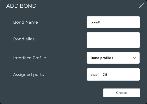
Enter a unique name for the bond.
Optionally enter an alias for the bond.
Select a bond profile from the dropdown. If you have not yet created one, follow the instructions in the Interface Profiles tab and then return here.
Assign the ports included in this bond. The port name is provided based on the switch type selection you made earlier. The port numbers are entered here.
When you are satisfied with the bond specification, click Create.
The bonds are displayed in the Bond list. Once bonds are in the list, they can be exported, modified, removed, and duplicated using the menu above the list. Simply select one, all, or filter for a subset of bonds, then click the relevant menu icon.
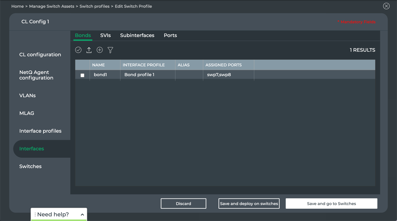
- Repeat these steps to add additional bonds as needed. Then continue to specifying SVIs.
Add SVIs
Add SVIs (switch virtual interfaces) to your switch configuration when you need a virtual interface at layer 3 to a VLAN. You must have at least one SVI interface profile specified to configure an SVI interface (return to the Interface Profiles tab and see Add SVI Interface Profiles if needed).
Click Interfaces.
Click SVIs.
Click Create if no SVIs exist, or click
to add a new SVI.
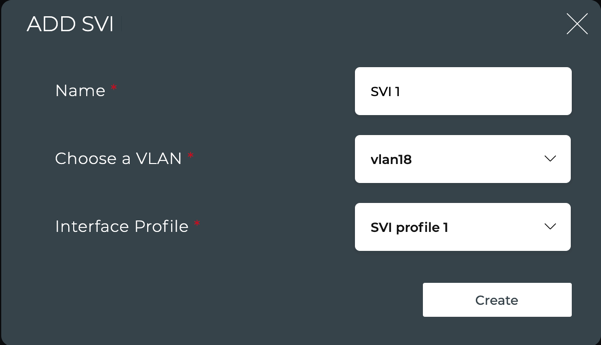
Enter a unique name for the SVI.
Select a VLAN to apply to this SVI.
Select an SVI profile to apply to this SVI. If you have not yet created one, follow the instructions in the Interface Profiles tab and then return here.
When you are satisfied with your SVI specification, click Create.
The SVIs are displayed in the SVI list. Once SVIs are in the list, they can be exported, modified, removed, and duplicated using the menu above the list. Simply select one, all, or filter for a subset of SVIs, then click the relevant menu icon.
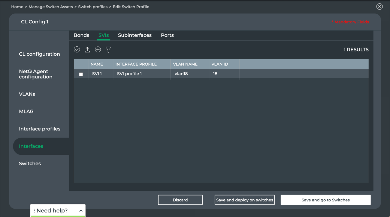
- Repeat these steps to add additional SVIs as needed. Then continue to specifying subinterfaces.
Add Subinterfaces
Add subinterface to your switch configuration when you want a VLAN associated with a given interface. You must have at least one subinterface interface profile specified to configure a bond interface (return to the Interface Profiles tab and see Add Subinterface Profiles if needed).
Click Interfaces.
Click Subinterfaces.
Click Create if no subinterfaces exist, or click
to add a new subinterface.
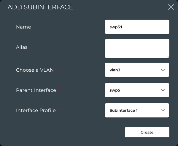
Enter a unique name for the subinterface in the format <parent-interface-name:vlan-subinterface-id>. For example, swp2:1.
Optionally enter an alias for this subinterface.
Select a VLAN to apply to this subinterface. This should match the name you specified in step 4.
Select a parent interface from the dropdown. This should match the name you specified in step 4.
Select a subinterface profile to apply to this subinterface.
When you are satisfied with your subinterface specification, click Create.
The subinterfaces are displayed in the subinterface list. Once subinterfaces are in the list, they can be exported, modified, removed, and duplicated using the menu above the list. Simply select one, all, or filter for a subset of subinterfaces, then click the relevant menu icon.
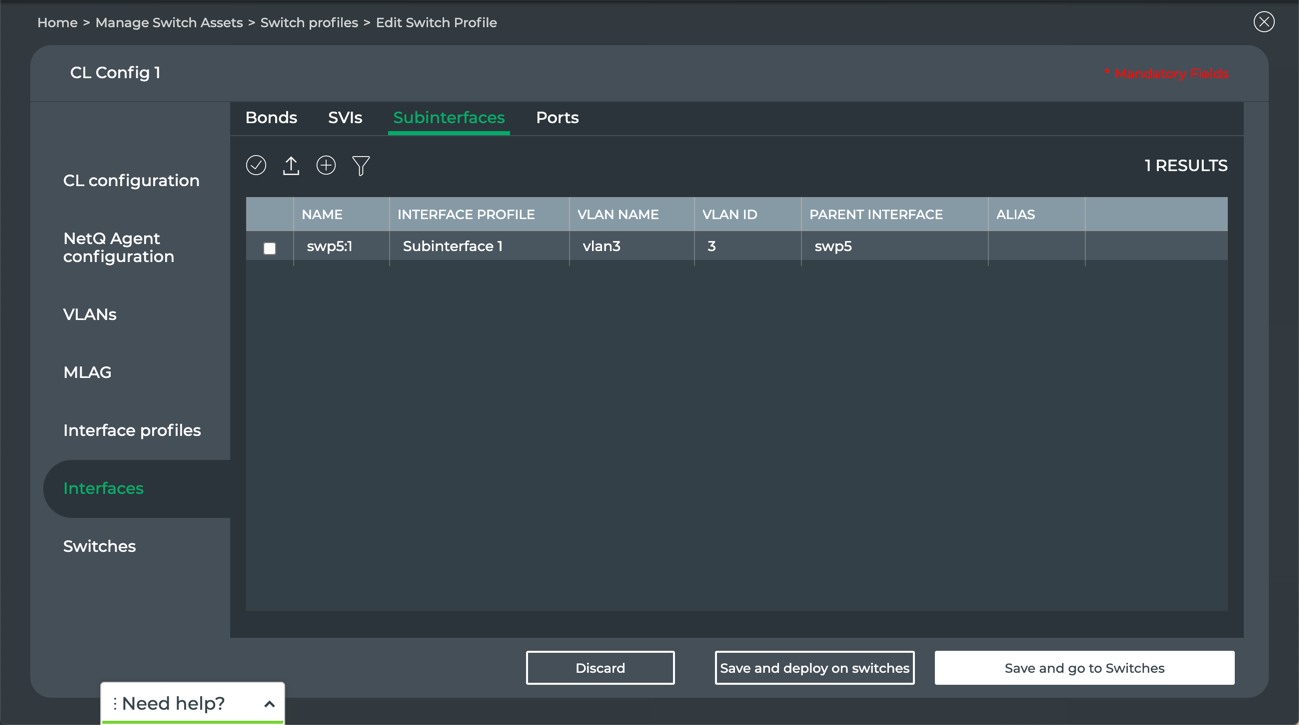
- Repeat these steps to add additional subinterfaces as needed. Then continue to specifying ports.
Add Ports
This tab describes all of the ports on the identified switch type. The port name and bond are provided by default (based on your previous switch configuration entries). For each port, you must define the speed and assign an interface profile. Optionally you can configure ports to be split to support multiple interfaces. Any caveats related to port configuration on the specified type of switch are listed under the port listing.
You must have at least one port interface profile specified to configure a port interface (return to the Interface Profiles tab and see Add Port Interface Profiles if needed).
Click Interfaces.
Click Ports.
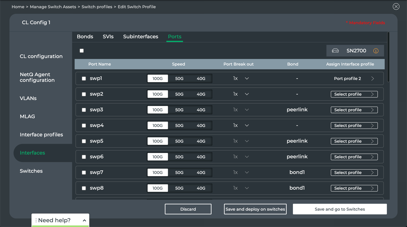
For each port, verify the port speed. For any port that should be other than the default highlighted, click on the alternate speed choice.
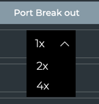
If you want to break out selected ports, choose the split value from the dropdown.
In the example above, swp1 has its speed set to 100 Gbps. On the Mellanox SN2700 switch being configured here, this port can then be broken into two 50 Gbps speed interfaces or four 25 Gbps speed interfaces. Some limitations on other ports can occur when you break out a given port. In this case, if we were to choose a 4x breakout, swp2 would become unavailable and you would not be able to configure that port.
If a port is missing a bond (all ports must have a bond), return to Interfaces > Bonds to assign it.
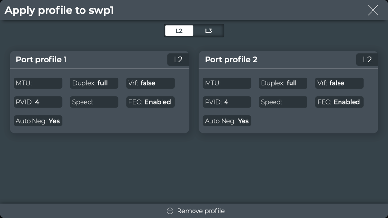
Assign an interface profile for each port by clicking on the Select profile link.
Click L2 or L3 to view available port profiles. If you have not yet created one, follow the instructions in the Interface Profiles tab and then return here.
Click on the port profile card to select it and return to the port list. If you accidentally select the wrong port profile, simply click on the profile name and reselect a different profile.
- When you are satisfied with the port specification for all ports, click one of the following:
- Discard to clear your entries and start again.
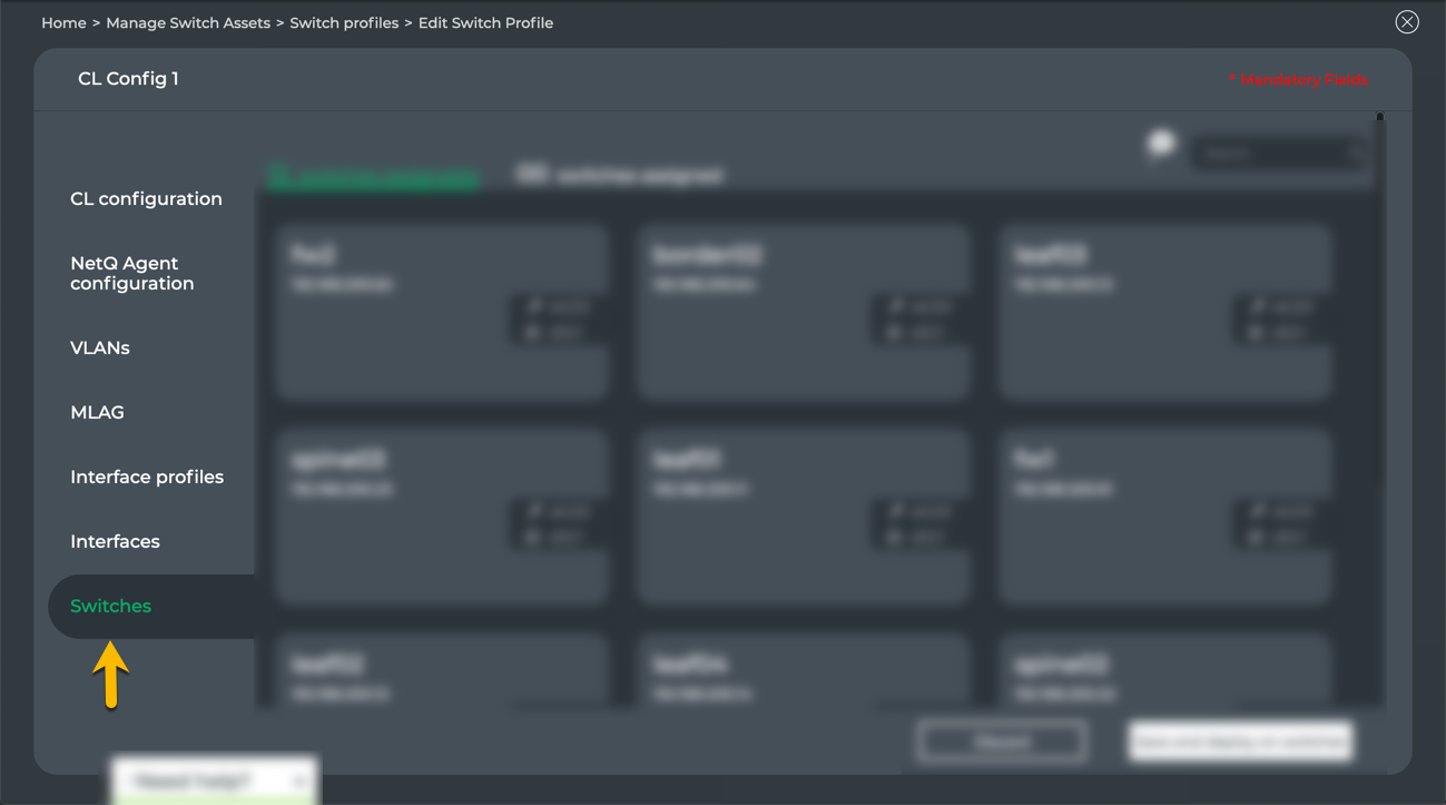
- Save and go to Switches to assign the switch configuration to switches now.
- Save and deploy on switches to complete the switch configuration and go to your switch configurations listing. You can edit the configuration to assign it to switches at a later time.
Assign Switch Configuration Profiles to Switches
After you have completed one or more switch configurations, you can assign them to one or more switches.
To assign a switch configuration:
Open the Switches tab in the switch configuration you want to assign:
If you have just completed creating a switch configuration and are still within the configuration page, simply click the Switches tab.
If you want to apply a previously saved configuration, click
on a workbench header > click Configuration Management > click Manage on the Switch Configurations card > locate the desired configuration > click > select Edit > click the Switches tab.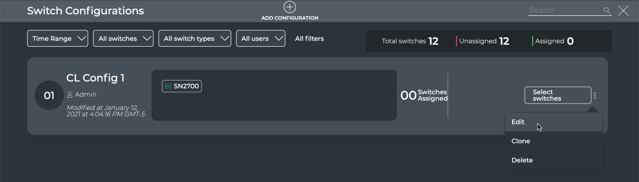
In either case, you should land on the switch configuration page with the Switches tab open.
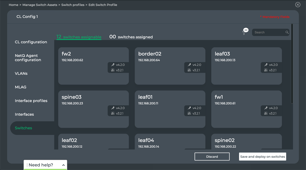
- Above the switches (left), the number of switches that can be assigned and the number of switches that have already been assigned a switch configuration
- Above the switches (right), management tools to help find the switches you want to assign with this configuration, including filter and search.
Select the switches to be assigned this configuration. Each switch selected must have items specified that are particular to that switch. This can be done in one of two ways:
- Select an individual switch by clicking on the switch card
- Filter or search for switches and then click Save and deploy on switches
Either way, a per-instance variables form appears for the selected or one of the selected switches.
This is an Early Access capability.
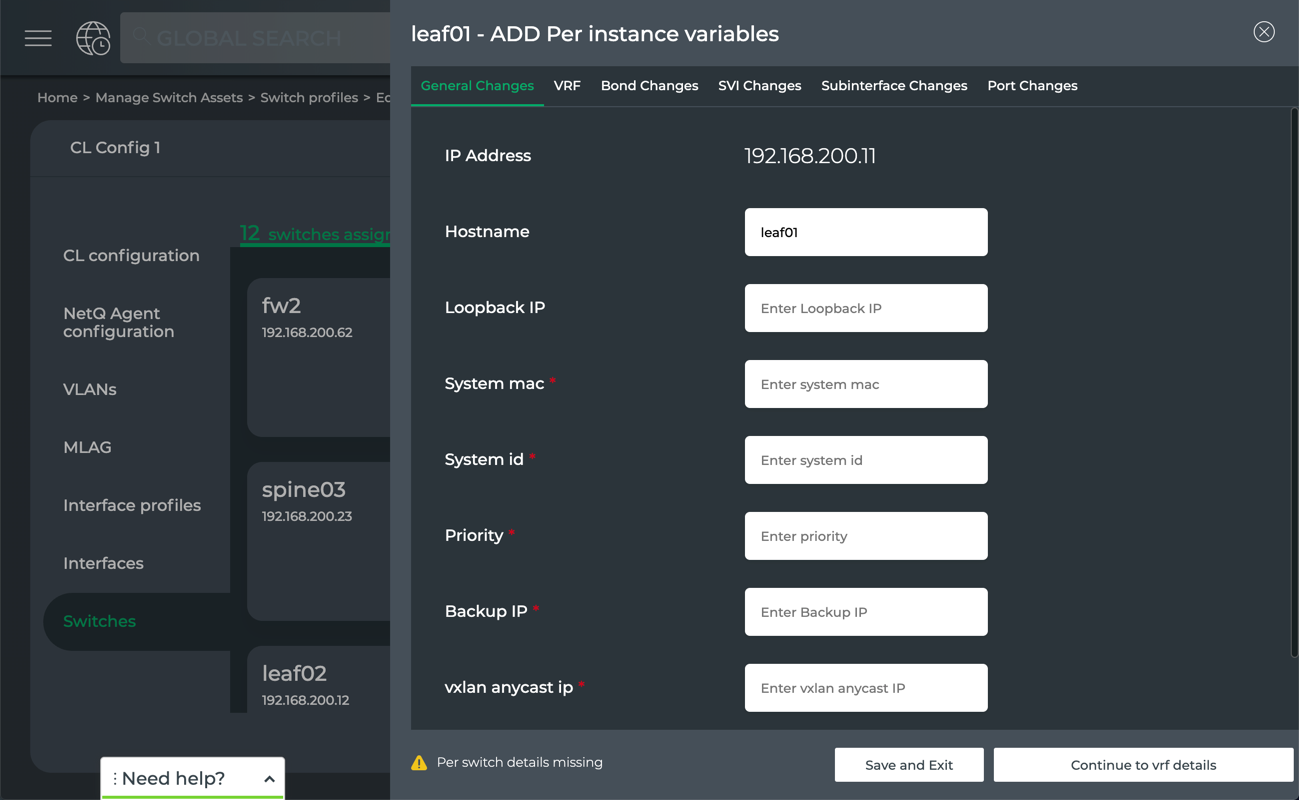
Enter the required parameters for each switch using the following instructions.
This is an Early Access capability.
Verify the IP address of the switch.
Optionally change the hostname of the switch.
Enter the loopback IP address for the switch.
Enter the System MAC address for the switch.
Enter the system ID for the switch.
Enter a priority for the switch in the format of an integer, where zero (0) is the lowest priority.
Enter a backup IP address for the switch in the event it becomes unreachable.
Enter a VXLAN anycast IP address for the switch.
Enter the name of a VRF for the switch.
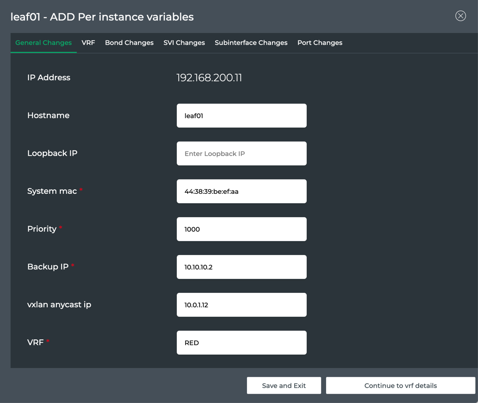
- Click Continue to vrf details, or click Save and Exit to come back later to finish the specification. If you choose to save and exit, click
 on the switch card to return to the per instance variable definition pages.
The VRF identified in General Changes is presented. Optionally add the associated IPv4 and IPv6 addresses for this VRF.
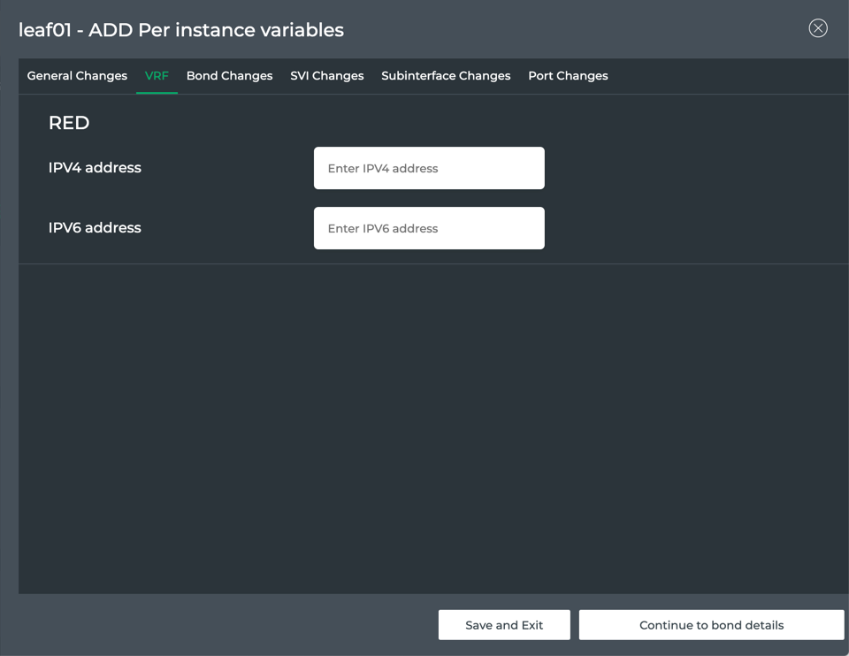
Click Continue to bond details, or click Save and Exit to come back later to finish the specification. If you choose to save and exit, click
on the switch card to return to the per instance variable definition pages. This topic is in development.
The SVIs specified are presented. If no SVIs are defined and there should be, return to the Interface Profiles and Interfaces tabs to specify them.
Optionally add the associated IPv4 and IPv6 addresses this switch should use for these SVIs.
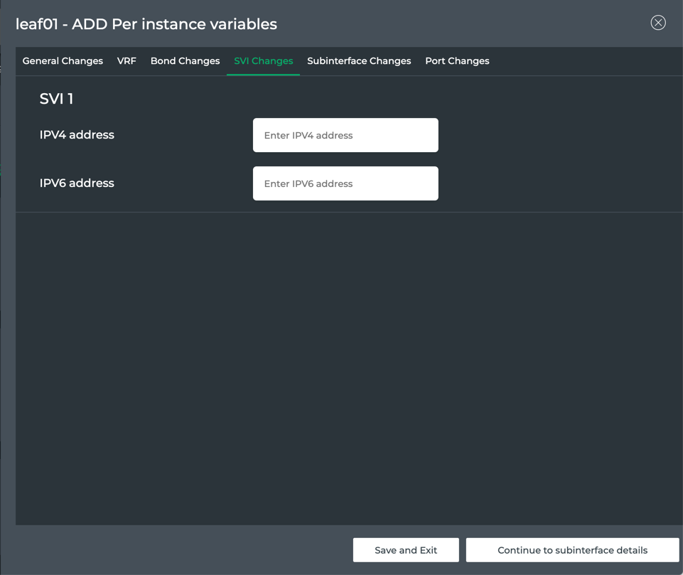
Click Continue to subinterface details, or click Save and Exit to come back later to finish the specification. If you choose to save and exit, click
on the switch card to return to the per instance variable definition pages.The subinterfaces specified are presented. If no subinterfaces are defined and there should be, return to the Interface Profiles and Interfaces tabs to specify them.
Optionally add the associated IPv4 and IPv6 addresses this switch should use for these subinterfaces.
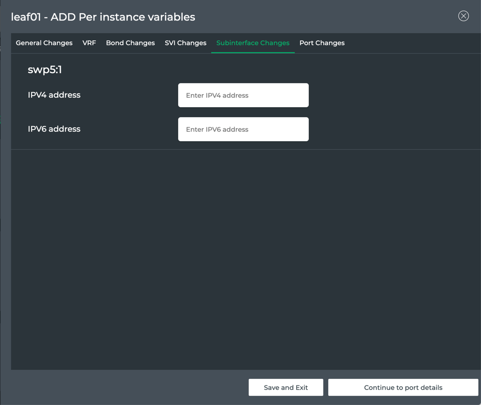
Click Continue to port details, or click Save and Exit to come back later to finish the specification. If you choose to save and exit, click
on the switch card to return to the per instance variable definition pages. This topic is in development.Click Save and Exit.
To run the job to apply the configuration, click Save and deploy on switches.
Enter a name for the job (maximum of 22 characters including spaces). Verify the configuration name and number of switches you have selected to assign this configuration to. then click Continue.
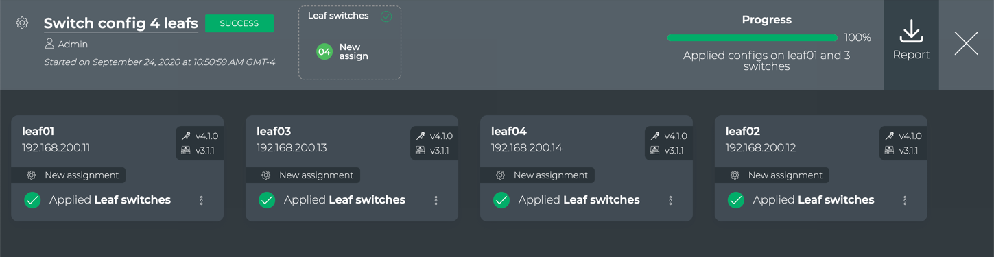
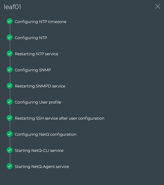
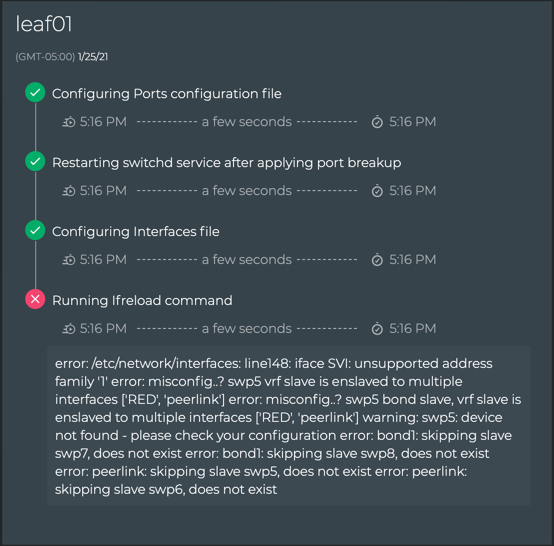
This opens the monitoring page for the assignment jobs, similar to the upgrade jobs. The job title bar indicates the name of the switch configuration being applied and the number of switches that to be assigned with the configuration. (After you have multiple switch configurations created, you might have more than one configuration being applied in a single job.) Each switch element indicates its hostname, IP address, installed Cumulus Linux and NetQ versions, a note indicating this is a new assignment, the switch configuration being applied, and a menu that provides the detailed steps being executed. The last is useful when the assignment fails as any errors are included in this popup.
Click
 to return to the switch configuration page where you can either create another configuration and apply it. If you are finished assigning switch configurations to switches, click
  to return to the lifecycle management dashboard.
When you return the dashboard, your Switch Configurations card on the Configuration Management tab shows the new configurations, and the Config Assignment History card appears on the Job History tab that shows a summary status of all configuration assignment jobs attempted.
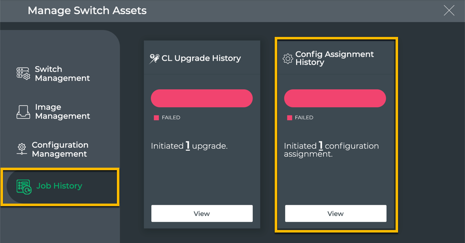
Click View on the Config Assignment History card to open the details of all assignment jobs. Refer to Manage Switch Configurations for more detail about this card.
Edit a Switch Configuration
You can edit a switch configuration at any time. After you have made changes to the configuration, you can apply it to the same set of switches or modify the switches using the configuration as part of the editing process.
To edit a switch configuration:
Locate the Switch Configurations card on the Configuration Management tab of the lifecycle management dashboard.
Click Manage.
Locate the configuration you want to edit. Scroll down or filter the listing to help find the configuration when there are multiple configurations.
Click
, then select Edit.Follow the instructions in Create Switch Configuration Profiles, starting at Step 5, to make any required edits.
Clone a Switch Configuration
You can clone a switch configuration assignment job at any time.
To clone an assignment job:
Locate the Switch Configurations card on the Configuration Management tab of the lifecycle management dashboard.
Click Manage.
Locate the configuration you want to clone. Scroll down or filter the listing to help find the configuration when there are multiple configurations.
Click
, then select Clone.Click
, then select Edit.Change the Configuration Name.
Follow the instructions in Create Switch Configuration Profiles, starting at Step 5, to make any required edits.
Remove a Switch Configuration
You can remove a switch configuration at any time; however if there are switches with the given configuration assigned, you must first assign an alternate configuration to those switches.
To remove a switch configuration:
Locate the Switch Configurations card on the Configuration Management tab of the lifecycle management dashboard.
Click Manage.
Locate the configuration you want to remove. Scroll down or filter the listing to help find the configuration when there are multiple configurations.
Click
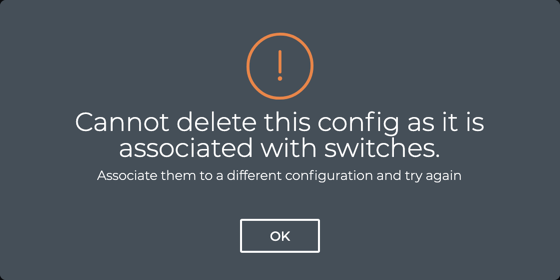
, then select Delete.If any switches are assigned to this configuration, an error message appears. Assign a different switch configuration to the relevant switches and repeat the removal steps.
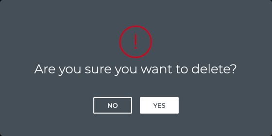
Otherwise, confirm the removal by clicking Yes.
Assign Existing Switch Configuration Profiles
You can assign existing switch configurations to one or more switches at any time. You can also change the switch configuration already assigned to a switch.
If you need to create a new switch configuration, follow the instructions in Create Switch Configuration Profiles.
Add an Assignment
As new switches are added to your network, you might want to use a switch configuration to speed the process and make sure it matches the configuration of similarly designated switches.
To assign an existing switch configuration to switches:
Locate the Switch Configurations card on the Configuration Management tab of the lifecycle management dashboard.
Click Manage.
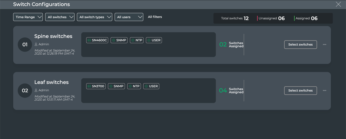
Locate the configuration you want to assign.
Scroll down or filter the listing by:
- Time Range: Enter a range of time in which the switch configuration was created, then click Done.
- All switches: Search for or select individual switches from the list, then click Done.
- All switch types: Search for or select individual switch series, then click Done.
- All users: Search for or select individual users who created a switch configuration, then click Done.
- All filters: Display all filters at once to apply multiple filters at once. Additional filter options are included here. Click Done when satisfied with your filter criteria.
By default, filters show all of the items of the given filter type until it is restricted by these settings.
Click Select switches in the switch configuration summary.
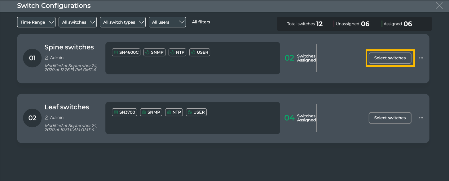
Select the switches that you want to assign to the switch configuration.
Scroll down or use the filter and Search options to help find the switches of interest. You can filter by role, Cumulus Linux version, or NetQ version. The badge on the filter icon indicates the number of filters applied. Colors on filter options are only used to distinguish between options. No other indication is intended.
In this example, we have three roles defined, and we have selected to filter on the spine role.
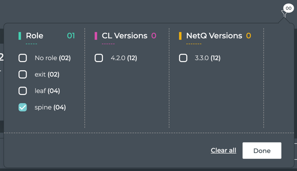
The result is four switches. Note that only the switches that meet the criteria and have no switch configuration assigned are shown. In this example, there are two additional switches with the spine role, but they already have a switch configuration assigned to them. Click on the link above the list to view those switches.
Continue narrowing the list of switches until all or most of the switches are visible.
Click on each switch card to be given the switch configuration.
When you select a card, if the per-switch variables have not already been specified, you must complete that first. Refer to Assign Switch Configuration Profiles to Switches beginning at step 2, then return here. If a switch has an incomplete specification of the required variables, click
to enter the required information.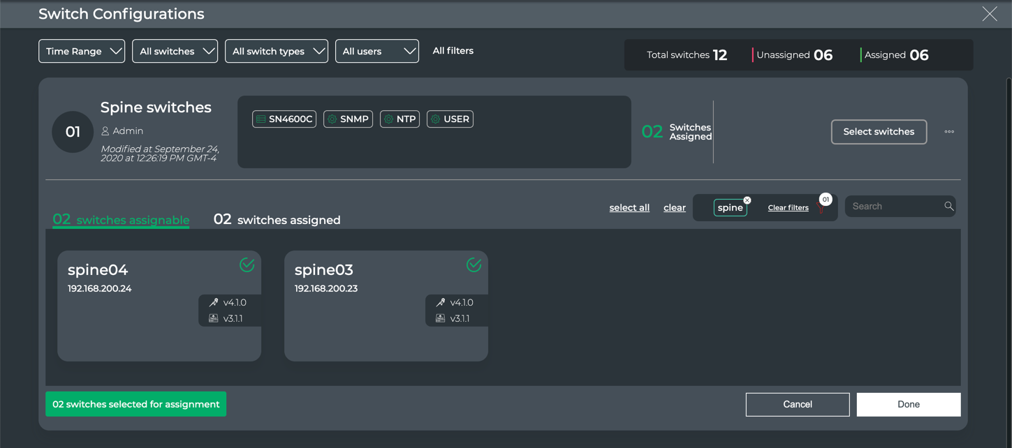
Verify all of the switches are selected that you want applied with this configuration, then click Done.
If you have additional switches that you want to assign a different switch configuration, follow Steps 3-7 for each switch configuration.
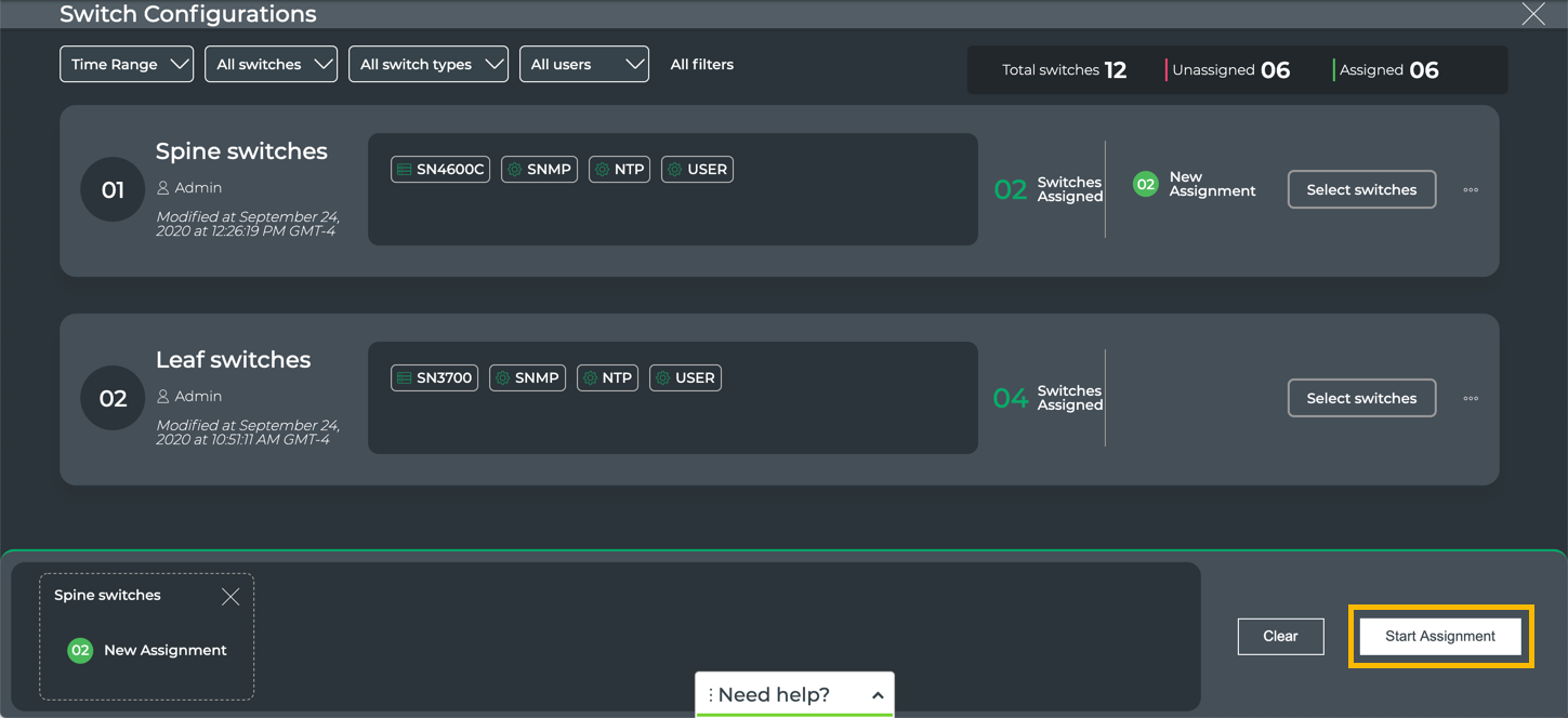
A job is created with each of the assignments configured. It is shown at the botton of the page. If you have multiple configuration assignments, they all become part of a single assignment job.
Click Start Assignment to start the job.
This example shows only one switch configuration assignment.
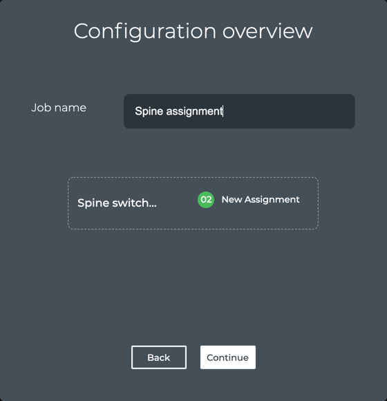
Enter a name for the job (maximum of 22 characters including spaces), then click Continue.
Watch the progress or click
to return to the switch configuration page where you can either create another configuration and apply it. If you are finished assigning switch configurations to switches, click to return to the lifecycle management dashboard.The Config Assignment History card on the Job History tab is updated to include the status of the job you just ran.
Change the Configuration Assignment on a Switch
You can change the switch configuration assignment at any time. For example you might have a switch that is starting to experience reduced performance, so you want to run What Just Happened on it to see if there is a particular problem area. You can reassign this switch to a new configuration with WJH enabled on the NetQ Agent while you test it. Then you can change it back to its original assignment.
To change the configuration assignment on a switch:
Locate the Switch Configurations card on the Configuration Management tab of the lifecycle management dashboard.
Click Manage.
Locate the configuration you want to assign. Scroll down or filter the listing to help find the configuration when there are multiple configurations.
Click Select switches in the switch configuration summary.
Select the switches that you want to assign to the switch configuration.
Scroll down or use the filter and Search options to help find the switch(es) of interest.
Click on each switch card to be given the switch configuration.
When you select a card, if the per-switch variables have not already been specified, you must complete that first. Refer to Assign Switch Configuration Profiles to Switches beginning at step 2, then return here. If a switch has an incomplete specification of the required variables, click
to enter the required information.Click Done.
Click Start Assignment.
Watch the progress.
On completion, each switch shows the previous assignment and the newly applied configuration assignment.
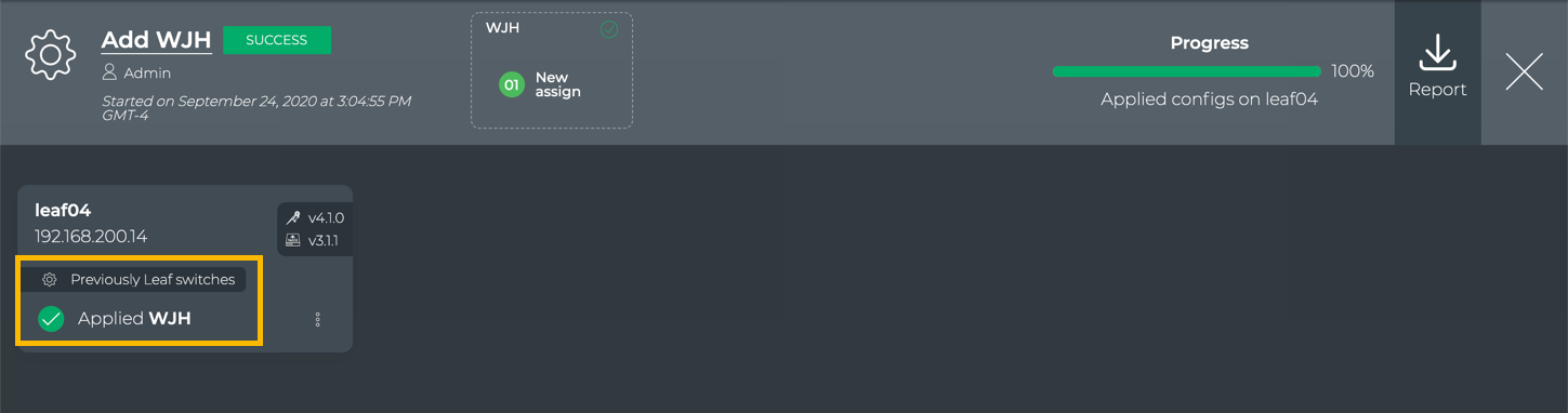
Click
to return to the switch configuration page where you can either create another configuration and apply it. If you are finished assigning switch configurations to switches, click to return to the lifecycle management dashboard.The Config Assignment History card on the Job History tab is updated to include the status of the job you just ran.
View Switch Configuration History
You can view a history of switch configuration assignments using the Config Assignment History card.
To view a summary, locate the Config Assignment History card on the lifecycle management dashboard.
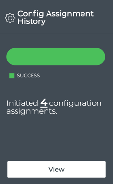
To view details of the assignment jobs, click View.
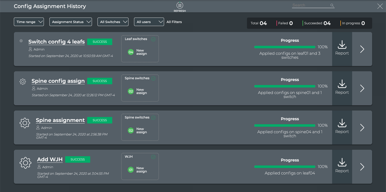
Above the jobs, a number of filters are provided to help you find a particular job. To the right of those is a status summary of all jobs. Click ![]() in the job listing to see the details of that job. Click
in the job listing to see the details of that job. Click ![]() to return to the lifecycle management dashboard.
to return to the lifecycle management dashboard.