Extending the EVPN/VXLAN Fabric with DCI
This section describes how to extend EVPN and VXLAN fabrics across data centers and use EVPN and VXLAN to interconnect them. Because EVPN and VXLAN leverages control plane MAC learning, you need to extend the signaling (control plane) domain across data centers or interconnect multiple control plane domains.
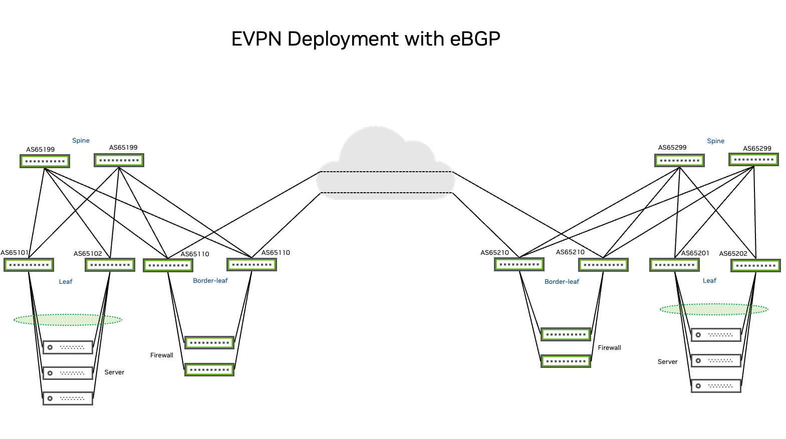
This environment demonstrates a best practice configuration for several use cases including layer 2 extension using EVPN signaling with type-1, type-2 and type-4 routes; layer 3 extension and routing using EVPN type-5 routes; and inter-VLAN routing using EVPN symmetric routing for distributed routing in an EVPN and VXLAN fabric. Examples also provide a route leaking scenario for inter POD communication.
The configuration examples use the NVUE Object Model and NVUE CLI to set an all-active-server-redundant environment with EVPN multihoming to configure an EVPN fabric with standardized layer 2 redundancy on ToR (top-of-rack) switches. All PODs that this document references belong to the same administrative domain or are under the same organization. This document does not address interconnects of different fabrics belonging to different administrative domains. The design on each POD is orthogonal to the other.
When using the symmetric model, each VTEP bridges and routes traffic (ingress and egress). The leaf ingress host port bridges layer 2 traffic (through the VLAN and layer 2 VNI), then routes the traffic to a special transit VNI called a layer 3 VNI, which all routed VXLAN traffic uses. You must route all VXLAN traffic to this layer 3 VNI, tunnel the traffic across the layer 3 infrastructure, and route off the layer 3 VNI to the appropriate VLAN at the destination VTEP. The traffic is then bridged to the destination host.
In this model, the leaf switches only need to host the VLANs (mapped to VNIs) located on the rack, the layer 3 VNI, and its associated VLAN. This is because the ingress leaf switch does not need to know the destination VNI.
Multitenancy requires one layer 3 VNI per VRF, and you must configure all switches participating in that VRF with the same layer 3 VNI. The egress leaf uses the layer 3 VNI to identify the VRF that routes the packet. For additional examples, refer to the Cumulus Linux documentation and EVPN traffic flows in a virtualized environment.
EVPN multihoming (EVPN-MH) is the standards-based MLAG replacement for providing layer 2 server redundancy on the top-of-rack level.
BUM Traffic
Head-end-replication (HER), or ingress replication, uses an inclusive multicast Ethernet tag (IMET) route (type-3) to automatically discover remote PEs to set up BUM traffic over VXLAN. This is the default configuration option. You can also use Protocol-Independent Multicast Sparse Mode (PIM-SM); however for DCI environments, PIM design is complex and requires additional planning. Keep in mind that most third-party E-LINE, E-LAN, layer 3 VPN, and VPWS service providers do not support multicast traffic. For data center interconnect over dark fiber, DWDM using multicast underlay routing with PIM-SM presents a significant multicast network design challenge. NVIDIA recommends HER for DCI.
Design your EVPN and VXLAN Fabric
The section covers the basic considerations for designing your DCI EVPN and VXLAN fabric. For detailed information, refer to the Cumulus Linux VXLAN and EVPN Network Reference Design Guide.
Plan an Autonomous System Number Schema
The following is a list of autonomous system (AS) numbering schema considerations across the DCI EVPN fabric:
- Assign a unique identifier (AS number) to each logical group of devices.
- Assign each leaf its own, unique AS number.
- Assign each group of spines (all the spines connected to the same set of leaf switches or PODs) a common AS number. Each POD in the network must have a unique set of AS numbers for its spines.
- Assign each group of super spines (connected to the same set of spines) a common AS number.
- Assign each border leaf pair (or triplet) belonging to the same POD a common AS number. Each POD in the network must have a unique set of AS numbers on its border leafs.
Assigning each border leaf pair a common AS number prevents locally advertised prefixes from each POD from circling back over the redundant path through the border leafs of the interconnected POD (through the DCI). A single DCI link in between PODs avoids this problem, as there is only one path between each POD, without any redundancy. However, a common AS number on border leafs prevents them from serving hosts with EVPN-MH connections, as EVPN-MH requires different AS numbers on participating leafs.
Underlay and Overlay Considerations
EVPN-VXLAN is an overlay technology that creates a topology-independent underlay fabric. Decoupling the underlay from the overlay creates a network with multitenancy, redundancy, and host mobility across a vendor-agnostic ecosystem. However, to establish VXLAN tunnels from leaf to leaf, the network must distribute tunnel source addresses (usually a loopback) using an underlay routing protocol. This allows all VXLAN peers to have the host route of each tunnel destination as a /32 prefix in their routing tables. This is a fundamental principle of EVPN and VXLAN—each leaf requires a host route of all the corresponding PE VXLAN tunnel destination addresses in its routing table so that it can establish end-to-end VXLAN tunnels.
The following command shows the VXLAN tunnel destination address of the corresponding PE:
cumulus@leaf01:mgmt:~$ nv show nve vxlan source
         operational  applied
-------  -----------  ----------
address  10.10.10.1   10.10.10.1
Apply the VXLAN tunnel source address configuration with the following NVUE configuration statement:
nv set nve vxlan source address 10.10.10.1
For the underlay, any well-known IGP that can quickly converge and provide multipath is sufficient, such as OSPF, IS-IS, and BGP. OSPF is popular in enterprise environments and is a safe choice. However, OSPF has been rejected by web-scale operators due to its lack of multiprotocol support. Enterprise environments use OSPFv2 because IGP is designed for IPv4, whereas OSPFv3 is for IPv6. If your network requires an OSPF-only underlay with multiprotocol support, you must run two separate instances of OSPF.
For IS-IS, many operators feel that a link-state protocol is inherently unsuited for a richly connected network such as the Clos topology. Link state protocols propagate link state changes to all routers in their respective area, even to routers that have no direct connection or dependency on the failed link.
BGP addresses these limitations and is designed to scale and provide a loop-free topology at any size. BGP powers the internet, is well known to engineers, and has a standardized implementation across the entire vendor ecosystem. BGP is less chatty than link state routing protocols and natively supports multi-protocol extensions (IPv4, IPv6, MPLS, and EVPN). However, BGP requires a few modifications to operate in a data center.
So, do you use iBGP, eBGP, or both in an underlay and overlay environment? Given that the entire network is under the same administrative domain and belongs to the same entity or company, iBGP might be the obvious choice. However, in modern data centers eBGP is the most common deployment model because it is simpler to understand and deploy than iBGP. The iBGP path-selection algorithm, and the rules that govern which routes are forwarded, can be confusing. There are also limitations to iBGP multipath support under certain conditions, such as when a route is advertised by two different nodes. And there is still no consensus on the positioning of iBGP route reflectors.
The routing protocol stack that Cumulus Linux uses is FRR. With Cumulus Linux, FRR uses a data center profile configuration that sets the hold timer to nine seconds and the keepalive timer to three seconds to reduce the BGP default convergence timers. As a result, BGP in a data center environment has a unique behavior, detailed extensively in BGP in the Data Center.
This document focuses on eBGP as an underlay and overlay environment, and uses the default routing instance (VRF) for underlay communication and to distribute VTEP sources. The document uses non-default (also non-management) VRF instances for individual EVPN tenants.
Plan Route Targets and Route Distinguishers
When there is no explicit configuration for RD and RT import and export statements for a VNI, Cumulus Linux derives them automatically using the <vxlan-local-tunnelip>:<VNI> format for the RD and the <AS>:<VNI> format for the RT. Although you can explicitly define an RD per VNI, you can also automatically derive it by not defining an RD.
Route targets define to which VPN a BGP learned or locally injected prefix belongs. Route targets are the mechanism you use to control VPN prefix memberships. A prefix can be a member of a single VPN or multiple VPNs; therefore, do not use automatically generated route targets and use the auto import and export functionality instead. The examples in this document manually define the route targets, and import and export them. When you use different VNIs for each DC location or POD (downstream VNI), make sure that import statements cover the corresponding route targets.
Plan Ethernet Segment Identifiers
Ethernet segment identifiers (ESIs) define multihomed Ethernet segments and use EVPN type-1 and type-4 routes. To extend layer 2 across data centers, these routes are also exchanged over DCI and ESIs local to a POD. They operate across the entire EVPN fabric and must be unique for each Ethernet segment. Cumulus Linux derives a 10-byte ESI value (type 3) from the Ethernet segment system MAC address (6-byte) and a local discriminator value (3-byte).
You can also plan and configure the ESI numbering scheme across the entire fabric manually. You must have a unique ESI, which you can configure with the following command:
cumulus@switch:~$ nv set interface <interface> evpn multihoming segment identifier <ESI number>
The ESI number for the configuration must start with 00, which indicates if the operator manages and configures the ESI. You must separate the numbers with colons, for example 00:00:00:00:00:00:aa:00:00:01.
For a layer 3 extension (VRF handover), where you only exchange type-5 prefixes, ESI numbers are less significant because type-1 and type-4 prefixes do not pass on to the DCI. Consistent, unique ESIs across the fabric are a design best practice.