Data Center Networking Concepts
Overlay, Underlay, and Tunneling
Network virtualization is the carving up of a single physical network into many virtual networks. Virtualizing a resource allows it to be shared by multiple users. In the case of virtual networks, each user is under the illusion that there are no other users of the network. To preserve the illusion, virtual networks are isolated from one another.
A virtual network implemented with protocols that leave the transit nodes unaware of it is called a virtual network overlay. An underlay is the network that transports the overlay network. Underlay networks can be L2 or L3 networks. L2 underlay networks today are typically based on Ethernet, with segmentation accomplished through VLANs. Internet is an example of an L3 underlay network, where autonomous systems use interior gateway protocols (IGPs) such as OSPF and IS-IS to run control planes, and use BGP as the Internet-wide routing protocol. MPLS networks are a legacy underlay WAN technology that falls between L2 and L3. Overlay networks implement network virtualization concepts, where L2 and L3 tunneling encapsulation VXLAN, GRE and IPSec serves as the transport overlay protocol, sometimes referred to as OTV (Overlay Transport Virtualization).
In data centers, the role of the underlay is to provide reachability for the entire network. The underlay doesn’t actually have any intelligence to keep track of the endpoints or define the end-to-end networking. It provides the ability for all devices in the network to communicate with each other. In overlay environments, routing information is typically aggregated in top-of-rack switches (for bare-metal endpoints) or server hypervisors (for virtualized workloads).
In an overlay virtual network, a tunnel endpoint is termed a network virtualization edge (NVE). The ingress NVE, which marks the start of the virtual network overlay, adds the tunnel header. The egress NVE, which marks the end of the virtual network overlay, strips off the tunnel header.
The tunnel header can be constructed using an L2 header or an L3 header. Examples of L2 tunnels include double VLAN tag (Q-in-Q or double-Q), TRILL, and Mac-in-Mac (IEEE 802.1ah). Popular L3 tunnel headers include VXLAN, GRE, and MPLS.
Benefits of Using Overlay
Some of the benefits of the virtual network overlays over non-overlays include:
- Scalability. Virtual network overlays scale much better. Because the network core does not have to store forwarding table state for the virtual networks, it operates with much less state. As a consequence, a single physical network can support a larger number of virtual networks.
- Rapid provisioning. Virtual network overlays allow for rapid provisioning of virtual networks. Rapid provisioning is possible because you configure only the affected edges, not the entire network.
- Reuse of existing equipment. Only the edges participating in the virtual networks need to support the semantics of virtual networks. This also makes overlays extremely cost effective. If you want to try out an update to the virtual network software, only the edges need to be touched, whereas the rest of the network can hum along just fine.
- Independence from geographical location. As long as end to end MTU permits, overlay networks can transport endpoint traffic across domains as if they’re directly attached to each other. This makes disaster recovery and data replication very easy. As most of the modern overlay technologies are pure IP based and the whole internet supports IP, overlay networks allow you to interconnect domains over a shared environment.
Virtual Extensible LAN
Many data centers today have moved from a legacy L2 design to a modern L3 architecture. L3 designs allow simplified troubleshooting, clear upgrade strategies, multi-vendor support, small failure domains, and less vendor lock-in. However, many applications, storage appliances and tenant considerations still require L2 adjacency.
VXLAN is widely deployed in many L3 data centers to provide L2 connectivity between hosts for specific applications. This is done by encapsulating L2 frames in L3 packets. VXLAN is an Overlay Technology as it allows you to stretch L2 connections over an intervening L3 network by encapsulating (tunneling) Ethernet frames in an IP-UDP packet with a VXLAN header.
When a host sends traffic that belongs to a VNI, as shown in figure 2, the traffic is encapsulated in UDP and IP headers. This is then sent across the underlay network, just like normal IP traffic. When the packet reaches the destination switch, the packet is decapsulated and delivered to the destination server.
Figure 2 - VXLAN Communication
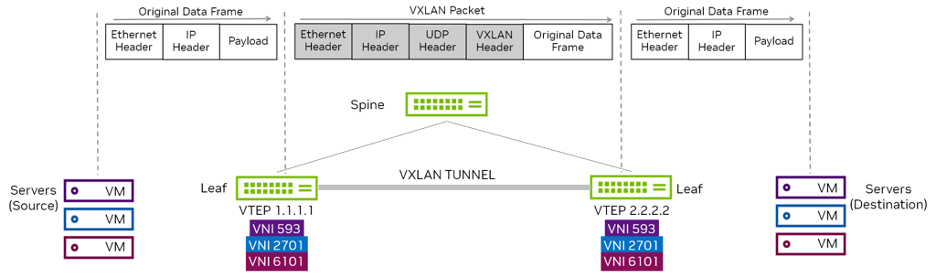
In the 2 tier leaf-spine topology, the leaf switches handle all the VXLAN functions that include creating the virtual networks and mapping VLANs to VNIs. The spine switches just pass traffic and are unaware that VXLAN even exists. By using VXLAN here, scaling the overlay network does not affect the underlay, and the other way round.
Virtual Tunnel Endpoints
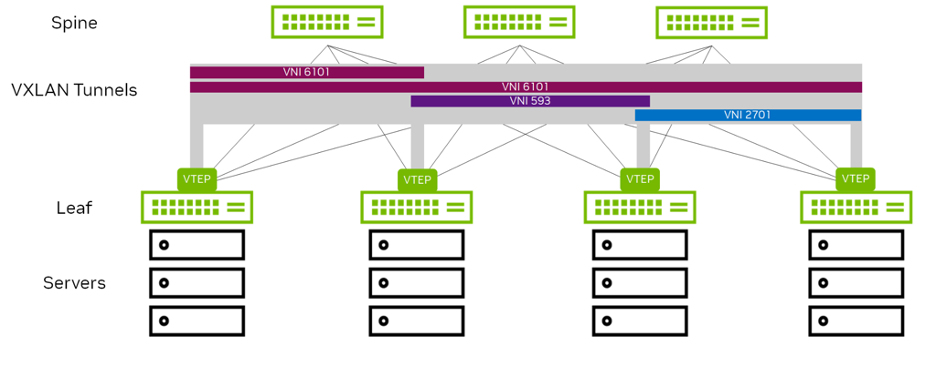
VTEPs are used to originate and terminate the VXLAN tunnel, and map a VLAN to a VNI and a VNI to a VLAN. As shown above in Figure 2, a VTEP is an edge device on a VXLAN network. It is either the start of a VXLAN tunnel, where the user data frame is encapsulated, or the end point of a VXLAN tunnel, where the user data frame is decapsulated.
These are the top-of-rack switches (for bare-metal endpoints) and server hypervisors (for virtualized workloads). A VTEP requires an IP address (often a loopback address) and uses this address as the source/destination tunnel IP address. The VTEP IP address must be advertised into the routed domain so the VXLAN tunnel endpoints can reach each other. You can have multiple VNIs (VXLANs) using one VTEP IP address. Each switch that hosts a VTEP must have a VXLAN-supported chipset, such as Spectrum. VXLAN is a point-to-multipoint tunnel. Multicast or broadcast packets can be sent from a single VTEP to multiple VTEPs in the network.
Figure 3 - VXLAN Tunnel and VTEPs within a Data Center
Benefits of Using VXLAN
VXLAN is an overlay technology that uses encapsulation to allow L2 overlay VLANs to span across L3 networks. L2 networks have some inherent disadvantages:
- Because they rely on STP, the capability for redundancy and multiple paths is limited by the functionality of spanning tree.
- Using STP downscales the size and radius of an L2 segment due to characteristics and limitations of STP itself.
- Due to its characteristics, an L2 broadcast domain also defines the blast radius of a network. The larger L2 domain (with or without STP being used) also refers to the larger blast-radius.
- STP convergence is very slow.
- Redundancy is normally only limited to two devices due to MLAG.
VXLAN overcomes these deficiencies and allows the network operator to optimize on an L3 routed fabric. A L2 overlay can still be accomplished, but no longer requires STP for control plane convergence due to the reliance of EVPN as the control plane. EVPN exchanges MAC information through a BGP address family, instead of relying on the inefficiencies of broadcast flood and learn. Plus, VXLAN uses a 24-bit ID that can define up to 16 million virtual networks, whereas VLAN only has a 12-bit ID and is limited to 4094 virtual networks.
Border Gateway Protocol
BGP is the routing protocol that runs the Internet. It manages how packets get routed from network to network by exchanging routing and reachability information.
BGP is an increasingly popular protocol for use in the data center as it lends itself well to the rich interconnections in a Clos topology.
BGP directs packets between autonomous systems (AS), which are a set of routers under a common administration. Each router maintains a routing table that controls how packets are forwarded. Because BGP was originally designed to peer between independently managed enterprises and service providers, each such enterprise is treated as an AS responsible for a set of network addresses. Each such AS is given a unique number called an autonomous system number (ASN).
The ASN is central to how BGP builds a forwarding topology. A BGP route advertisement carries with it not only the ASN of the originator, but also the list of ASNs that this route advertisement passes through. When forwarding a route advertisement, a BGP speaker adds itself to this list. This list of ASNs is called the AS path. BGP uses the AS path to detect and avoid loops.
When you use BGP to peer between autonomous systems, the peering is eBGP. When you use BGP within an autonomous system, the peering is iBGP. eBGP peers have different ASNs while iBGP peers have the same ASN. The recommendation is to use eBGP for EVPN deployments.
Auto BGP
In a two-tier leaf and spine environment, you can use Auto BGP to generate 32-bit ASNs automatically so that you do not have to think about which numbers to configure. Auto BGP helps build optimal ASN configurations in your data center to avoid suboptimal routing and path hunting, which occurs when you assign the wrong spine ASNs. Auto BGP makes no changes to standard BGP behavior or configuration.
To use auto BGP to assign an ASN automatically on the leaf:
nv set router bgp autonomous-system leaf
To use auto BGP to assign an ASN automatically on the spine:
nv set router bgp autonomous-system spine
The auto BGP leaf and spine keywords are only used to configure the ASN. The configuration files and nv show commands display the AS number.
BGP Unnumbered
One of the requirements for BGP to establish peering is to have IP addresses configured for L3 communication.This requires IPv4 and IPv6 address configuration on links connecting neighboring routers, which in a large network can consume a lot of address space and can require a separate IP address for each peer-facing interface. The BGP neighbors only connect and exchange routes when all of the configurations are correct. Configuring BGP in large data centers can be repetitive, time-consuming, and error-prone. BGP unnumbered helps to avoid these issues.
The BGP unnumbered standard in RFC 5549 uses ENHE and does not require that you advertise an IPv4 prefix together with an IPv4 next hop. You can configure BGP peering between your Cumulus Linux switches and exchange IPv4 prefixes without having to configure an IPv4 address on each switch; BGP uses unnumbered interfaces.
The next hop address for each prefix is an IPv6 link-local address, which BGP assigns automatically to each interface. Using the IPv6 link-local address as a next hop instead of an IPv4 unicast address, BGP unnumbered saves you from having to configure IPv4 addresses on each interface.
The following example commands show a basic BGP unnumbered configuration for two switches, leaf01 and spine01, which are eBGP peers. As seen below, the only difference in a BGP unnumbered configuration is that the BGP neighbor is an interface and not an IP address.
leaf01 configuration
nv set router bgp autonomous-system 65101
nv set router bgp router-id 10.10.10.1
nv set vrf default router bgp neighbor swp51 remote-as external
nv set vrf default router bgp address-family ipv4-unicast network 10.10.10.1/32
nv set vrf default router bgp address-family ipv4-unicast network 10.1.10.0/24
nv config apply
spine01 configuration
nv set router bgp autonomous-system 65199
nv set router bgp router-id 10.10.10.101
nv set vrf default router bgp neighbor swp1 remote-as external
nv set vrf default router bgp address-family ipv4-unicast network 10.10.10.101/32
nv config apply
Design Considerations
- Use auto BGP in new deployments to avoid conflicting ASNs in an existing configuration.
- BGP unnumbered simplifies configuration and is recommended to be used in data center deployments.
Route Distinguisher (RD) and Route Target (RT)
Route Distinguisher
Virtual networks allow the reuse of an address. In other words, an address is unique only within a virtual network. A common, well understood example of this is the use of the 10.x.x.x subnet in IPv4. The 10.x address space is a private address space, so different organizations can reuse the address with impunity. Similarly, different virtual networks can reuse the same 10.x IPv4 address. This is true also for L2 addresses. So, BGP needs to keep the Building Blocks of Ethernet VPN separate from the advertisement of an address in one virtual network from the advertisement of the same address in a different virtual network. That is the job of a RD.
When exchanging VPN addresses, BGP prepends an 8-byte RD to every address. This combination of RD plus address makes the address globally unique. The RD format used for this purpose (RFC4364) is IP address + a unique number in the format of x.x.x.x:y this gives overlapping IP space uniqueness across EVPN domain, hence RD used in an EVPN domain must be unique.
Route Target
BGP advertisements carry path attributes, which provide extra information about a network address. They carry information such as the next hop IP address for a prefix, whether to propagate an advertisement, and so on, as encoded bits. Path attributes take several forms, including well-known attributes, communities, and extended communities. RT is a specific path attribute that encodes the virtual network it represents. A BGP speaker advertising virtual networks and their addresses uses a specific RT called the export RT. A BGP speaker receiving and using the advertisement uses this RT to decide into which local virtual network to add the routes. This is called the import RT. In a typical VPN configuration, you must configure both import and export RTs.
RD, RT, and BGP Processing
RD and RT both identify the virtual network from which a packet arrives. Every BGP implementation maintains two kinds of routing tables: a global one and one per virtual network. BGP runs the best-path algorithm on the global table to pick a single path to advertise for each prefix to its peers. Because the RD is unique to each originator, all copies of a route are advertised to a neighbor. To install routes into a virtual network’s routing table, BGP first uses the import RT clause to select specific candidate routes from the global table to import into this virtual network. Then, it runs the best-path algorithm again on the imported candidate routes, but this time within the context of the virtual network’s routing table. If the same address is advertised with multiple RTs, the best-path algorithm selects the best one.
Auto RD and RT
RD and RT are automatically generated using VLAN/VXLAN and VRF. When Free Range Routing (FRR) learns about a local VNI and there is no explicit configuration for that VNI in FRR, the switch derives the RD, and import and export RTs for this VNI automatically. The RD uses RouterId:VNI-Index and the import and export RTs use AS:VNI. For routes that come from an L2 VNI (type-2 and type-3), the RD uses the VXLAN local tunnel IP address (VXLAN-local-tunnelip) from the L2 VNI interface instead of the RouterId (VXLAN-local-tunnelip:VNI). EVPN route exchange uses the RD and RTs.
Cumulus Linux treats the import RT as *:VNI to determine which received routes apply to a particular VNI. This only applies when the switch auto-derives the import RT. If you do not want to derive RDs and RTs automatically or have an existing deployment with non-Cumulus switches that do not support auto RTs or work with a different schema, you can define them manually.
Ethernet Virtual Private Network
EVPN is a feature offered with Cumulus Linux that provides a scalable, interoperable end-to-end control-plane solution using Border Gateway Protocol (BGP). It is a standards-based protocol that can carry both L2 MAC and L3 IP information simultaneously to optimize routing and switching decisions. This control plane technology uses Multiprotocol BGP (MP-BGP) for MAC and IP address endpoint distribution, in turn minimizing flooding.
EVPN supports redundancy, load sharing, and multi-tenant segmentation. It provides virtual multi-point bridged connectivity between different L2 domains over an IP or IP/MPLS backbone network. EVPN also provides the benefit of fast convergence for host and VM mobility over VXLAN tunnels and ARP suppression.
With the advent of VXLAN in the data center, EVPN was adopted as the solution for network virtualization in the data center. Cumulus Linux supports the EVPN address family with both eBGP and iBGP peering. In a typical 2-tier Clos network where the leafs are VTEPs, if you use BGP sessions between the leafs and spines for underlay routing, the same sessions exchange EVPN routes. The spine switches act as route forwarders and do not install any forwarding state as they are not VTEPs. When the switch exchanges EVPN routes over iBGP peering, you can use OSPF as the IGP or resolve next hops using iBGP.
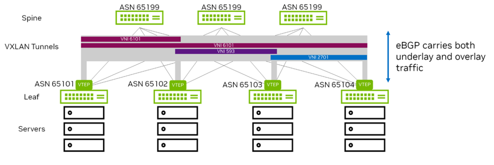
As shown in Figure 4, a typical data center uses just a few eBGP elements:
- Assign a unique identifier (AS number) to each logical group of devices.
- Assign each leaf its own identifier (AS number).
- Assign each group of spines (all the spines connected to the same set of leafs) a common identifier (AS number).
- Assign each group of super-spines (connected to the same set of spines) a common identifier (AS number).
- Set up peering between spine and leaf devices.
- Add a simple routing policy to share loopback address information.
- Add a routing policy to disallow leaf switches as transit devices.
- Enable load balancing.
Figure 4 - EVPN Deployment with eBGP
Benefits of Deploying EVPN
EVPN is a standardized control plane protocol that offers controller-less VXLAN tunnels. It also offers scale, redundancy, fast convergence and robustness while reducing broadcast, unknown unicast, and multicast (BUM) traffic across a data center core. Deploying EVPN provides many advantages to an L3 data center:
- Simplicity. EVPN uses the BGP routing protocol. BGP is also the preferred routing protocol for data center infrastructures. The same routing protocol can be used for both infrastructure and virtual topologies.
- Controller-less VXLAN tunnels. No controller is needed for VXLAN tunnels, as EVPN provides peer discovery with authentication natively. This also mitigates the chance of rogue VTEPs in a network and dealing with complicated controller redundancy, and scaling issues caused by controller.
- ARP Suppression. Cumulus EVPN reduces broadcast traffic within a data center by allowing the local leaf switch to respond to a host’s ARP requests instead of forwarding throughout the data center. Cumulus Linux enables ARP suppression by default.
- Scale and robustness. EVPN uses the BGP routing protocol. BGP is very mature, scalable, flexible and robust. It is the primary routing protocol for the Internet and data centers. It supports routing policy and filtering, which provides granular control over traffic flow.
- Fast convergence and host mobility. Cumulus EVPN supports the new BGP MAC mobility extended community, offering fast convergence and reducing discovery traffic after a MAC or VM move. MAC stickiness is also supported, preventing specific host mobility if desired.
- Support for VXLAN active-active mode. Cumulus EVPN integrates with MLAG and multihoming, thereby providing host dual homing for redundancy.
- Multitenancy. EVPN uses the RDs and RTs to separate tenants within a data center.
- VXLAN Routing. Cumulus EVPN supports IP routing between VXLAN VNIs in overlay networks and is supported with Spectrum chipsets. VXLAN routing within a VRF is also supported.
- Interoperability between vendors. The standardized multiprotocol BGP (MP-BGP) is used for the EVPN control plane. As long as vendor implementations maintain adherence to both the VXLAN and EVPN standards, interoperability is assured.
EVPN Route Types
Table 1 shows the different Route Types (RTs) used in EVPN. The minimum required RTs needed to operate an EVPN network are RT-2, RT-3, and RT-5. The rest are optional and dependent on the choices you make in building your network.
| Route Type | What it carries | Primary use |
|---|---|---|
| Type 1 | Ethernet Segment Auto Discovery | Used in the data center in support of multihomed endpoints. |
| Type 2 | MAC, VNI, IP | Advertises reachability to a specific MAC address, and optionally its IP address. |
| Type 3 | Inclusive Multicast Route | Required for Broadcast, Unknown Unicast and Multicast (BUM) traffic delivery across EVPN networks - provides information about P-tunnels that should be used to send the traffic. |
| Type 4 | Ethernet Segment Route | Discovers VTEPs attached to the same Ethernet Segment and for Designated Forwarder Election used for BUM traffic. |
| Type 5 | IP Prefix, L3 VNI | Advertises prefix (not /32 or /128), routes such as summarized routes in a virtual L3 network. |
| Type 6 | Multicast group membership info | Information about interested multicast groups derived from IGMP. |
| Type 7 | Multicast Membership Report Synch Route | IGMP synchronization mechanism that would allow all PE devices serving given ES to share their state - this route is used to coordinate the IGMP Membership Report. |
| Type 8 | Multicast Leave Synch Route | IGMP synchronization mechanism that would allow all PE devices serving given ES to share their state - this route is used to coordinate the IGMP Leave Group. |
| Type 9 | Per-region I-PMSI Auto Discovery | Auto-Discovery routes used to announce the tunnels that instantiate an Inclusive PMSI - to all PEs in the same VPN. |
| Type 10 | S-PMSI Auto Discovery | Auto-Discovery routes used to announce the tunnels that instantiate a Selective PMSI - to some of the PEs in the same VPN. |
| Type 11 | Leaf Auto Discovery | Used for explicit leaf tracking purposes. Triggered by I/S-PMSI A-D routes and targeted at triggering route’s (re-)advertiser. |
Multi-Chassis Link Aggregation and Multihoming
Multi-Chassis Link Aggregation (MLAG)
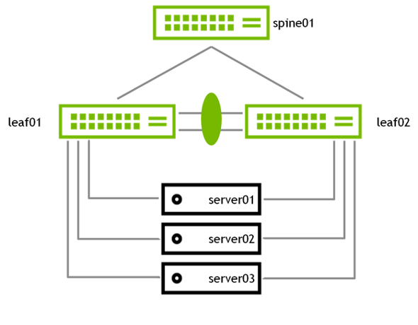
MLAG enables a pair of switches to act redundantly in an active-active architecture and appear as a single, logical device from the perspective of the host. The two switches in an MLAG pair are connected by a link or bonded links called the peer link. In a basic MLAG configuration, as shown in Figure 5, leaf01 and leaf02 are MLAG peers. MLAG is on three bonds, each with a single port, a peer link that is a bond with two member ports, and three VLANs on each port.
Figure 5 - Basic MLAG Cconfiguration
VRR enables a pair of switches to act as a single gateway for HA and Active-Active server links. VRR enables hosts to communicate with any redundant switch without reconfiguration by running dynamic router protocols or router redundancy protocols. Redundant switches respond to ARP requests from hosts. The switches respond in an identical manner, but if one fails, the other redundant switches continue to respond.
A device that connects to an MLAG bond believes there is a single device on the other end of the bond and only forwards one copy of the transit frames. With the virtual MAC active on both MLAG devices, either MLAG device handles the frame it receives. Cumulus Linux supports both VRR and VRRP. VRRP allows two or more network devices in an active or standby configuration to share a single virtual default gateway. However, VRRP cannot be used in an EVPN configuration.
Multihoming (EVPN-MH)
EVPN-MH is a standards-based replacement for the proprietary MLAG protocol in data center deployments. It provides an all-active server connectivity without the need for peer links between ToR switches. EVPN-MH enables multi-vendor interoperability with a single BGP-EVPN control plane. This protocol allows easier data center deployments without the need of understanding and using proprietary protocols.
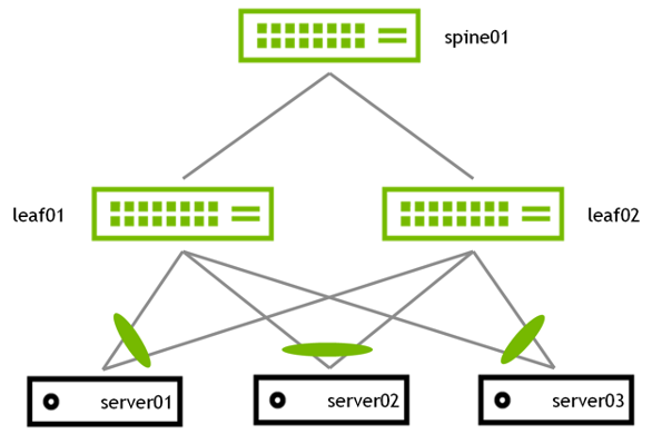
EVPN-MH uses BGP-EVPN type-1, type-2 and type-4 routes to discover Ethernet segments (ES) and to forward traffic to them. The MAC and neighbor databases synchronize between the ES peers through these routes as well. An ES is a group of switch links that attach to the same server. As seen in Figure 6, EVPN-MH eliminates the need for peer links or inter-switch links between the top of rack switch.
Figure 6 - Basic EVPN-MH Configuration
Design Considerations
Sometimes MLAG is still required in VXLAN environments for redundant host connectivity. EVPN-MH is an opportunity to move off proprietary MLAG solutions. Most MLAG systems allow dual homing across only two paths. In practice, MLAG systems are limited to dual core switches because it is extremely difficult to maintain a coherent state between more than two devices with submicrosecond refresh times. EVPN-MH, on the other hand, can scale beyond two leaf switches. VXLAN helps remove the need for back-to-back leaf-to-spine switch connections as required by MLAG. EVPN-MH goes one step further and eliminates any need for MLAG in server-to-leaf connectivity.
Multihoming uses EVPN messages to communicate host connectivity, and it dynamically builds L2 adjacency to servers using host connectivity information. Where MLAG requires LAG IDs, multihoming uses Ethernet segment IDs. Interfaces are mapped to segments that act like logical connections to the same end host. Additionally, moving to multihoming improves network vendor interoperability by using a protocol standard form of redundancy in the switch. Because multihoming is part of the EVPN address family, an open standard protocol, any vendor implementing multihoming through the RFC specification can be part of the Ethernet segment.
The switch selects a designated forwarder (DF) for each Ethernet segment. The DF forwards flooded traffic received through the VXLAN overlay to the locally attached Ethernet segment. You need to specify a preference on an Ethernet segment for the DF election, as this leads to predictable failure scenarios. The EVPN VTEP with the highest DF preference setting becomes the DF.
MLAG uses both uplinks at the same time. VRR enables both devices to act as gateways simultaneously for HA and active-active mode (both are used at the same time).
The disadvantages of using MLAG are:
- More complicated (more moving parts)
- More configuration
- No interoperability between vendors
- ISL (inter-switch link) required
- MLAG can be formed with a maximum of 2x leaf switches
Where possible, EVPN-MH is recommended over MLAG.
The advantages of using EVPN MH:
- You don’t need ISL anymore
- You can use BGP everywhere
- It is a standards-based implementation that can be used in a multivendor environment
- It can be formed with more than 2x leaves and can create more than two multihomed server-to-leaf connectivity for active-active load balancing and resiliency
To configure EVPN-MH:
- Enable EVPN multihoming:
nv set evpn multihoming enable on
- Set the Ethernet segment ID:
nv set interface bond1 bond member swp1
nv set interface bond2 bond member swp2
nv set interface bond3 bond member swp3
nv set interface bond1 evpn multihoming segment local-id 1
nv set interface bond2 evpn multihoming segment local-id 2
nv set interface bond3 evpn multihoming segment local-id 3
- Set the Ethernet segment system MAC address:
nv set interface bond1-3 evpn multihoming segment mac-address 44:38:39:BE:EF:AA
nv set interface bond1-3 evpn multihoming segment df-preference 50000
- Configure multihoming uplinks:
nv set interface swp51-54 evpn multihoming uplink on
nv config apply