EVPN Deployment Scenarios
EVPN for L2 Deployments
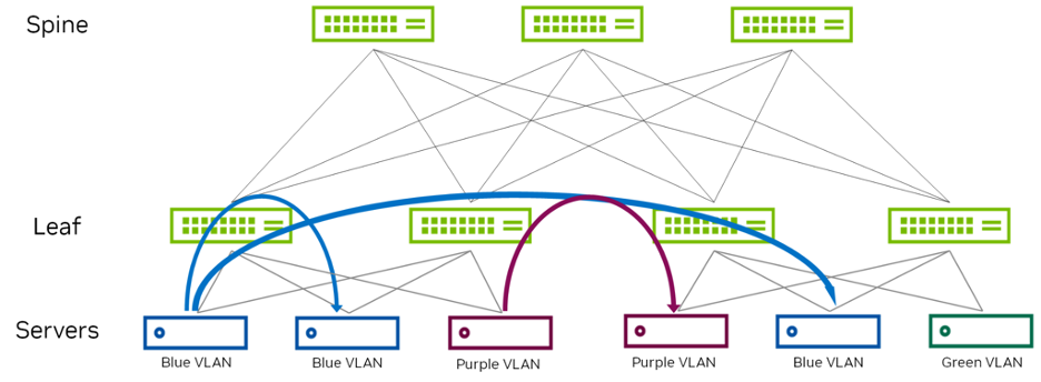
L2 EVPN deployment uses a bridged overlay as seen in Figure 7. It provides Ethernet bridging in an EVPN network and extends VLANs between the leaf devices across VXLAN tunnels. These leaf-to-leaf VXLAN tunnels are useful in networks that require connectivity between leaf devices but do not need inter-VLAN routing. As a result, the intelligence is at the leaf layer. The spine layer simply provides connectivity between leaf devices. Leaf devices establish VTEPs to connect to other leaf devices. The tunnels enable communication between leaf devices and Ethernet-connected end systems in the data center.
Figure 7 - L2 EVPN Example
STP is a L2 switching protocol, which ensures loop-free network topologies by always creating a single path tree structure through the network. If there is a link failure or the network is reconfigured, all network traffic is halted while the spanning tree algorithm recalculates the allowed loop-free paths. However, this is no longer necessary due to the inherent split-horizon functionality.
Points to consider:
- This is useful when L2 domains are divided by L3 fabrics and need to be stretched over them (such as legacy L2 applications, ESF, and so on.)
- Each ToR (leaf) is a VTEP and hosts the VLANs (mapped to VNIs) located on its rack.
- To have an extended L2 domain, the specific VNI has to be configured on the applicable VTEPs.
- Using this type of environment doesn’t allow inter-VLAN connectivity. For routing between different VNIs, we need to look at L3 deployment models or an external gateway, outside the fabric in order to perform routing between VLANs.
Scenarios to consider using L2 EVPN:
- When you have the subnet across the racks in a data center.
- When the architecture uses a firewall as the gateway. For example, if your security policy defines that all inter-VLAN traffic must go through a firewall, the L3 gateway functionality is provided by design outside the fabric, so the bridged overlay architecture is a good fit.
- When you have an existing Ethernet-based data center network and want to introduce EVPN/VXLAN. Because the bridged overlay approach is so basic and simple, it’s a good option when you want to modernize your DC environment, but you want to take a phased or incremental approach.
EVPN for L3 Deployments
Traditionally, data centers have used L2 technologies such as STP and MLAG. As data centers evolve and expand, they tend to outgrow their limits; STP blocks ports, which locks out needed bandwidth, while MLAG may not provide enough redundancy. Additionally, a device outage is a significant event and larger modular-chassis devices use a lot of power.
Routing Models
You might have to communicate between L2 domains and between a VXLAN tunnel and the outside world, for which you can enable VXLAN routing in the network.
VXLAN routing can be performed with one of two architectures:
- Centralized routing performs all the VXLAN routing on one or two centralized routers (routing on the border leaves), which is a good option for data centers with a lot of north-south traffic. This can cause additional east-west traffic in the data center.
- Distributed routing provides the VXLAN routing closest to the hosts on the directly connected leaf switches (routing in the leaf layer), which is a good option for data centers with a lot of east-west traffic. This simplifies the traffic flow.
BGP EVPN is used to communicate the VXLAN L3 routing information to the leaves.
Centralized Routing
The nature of a centrally routed bridging overlay is that routing occurs at a central gateway within the data center network (the border leaves, in this example) rather than at the VTEP device where end systems are connected (the leaf layer, in this example). You can use this overlay model when traffic needs to be routed through a centralized gateway or when edge VTEP devices lack the required routing capabilities.
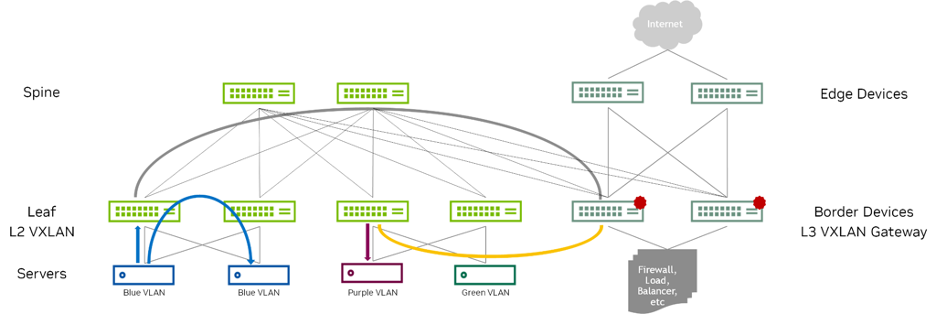
Figure 8 shows a common way to deploy this model. Border devices are located at the edge, or border, of a data center fabric. These devices also act as the VTEP for north-south traffic entering and exiting the network fabric. The traffic that originates at the Ethernet-connected end systems is forwarded to the leaf VTEP devices over a trunk (multiple VLANs) or an access port (single VLAN). The VTEP device forwards the traffic to local end systems or to an end system at a remote VTEP device. An integrated routing and bridging (IRB) interface at the border devices routes traffic between the Ethernet virtual networks.
Figure 8 - Centralized IRB Example
The main disadvantages of this approach are scalability and potentially non-optimal traffic flow.
Scenarios for using centralized IRB:
- The need for inter-VXLAN routing to happen within the fabric. This approach has the advantage of centralizing and consolidating the routing function (instead of distributing it at the leaf layer).
- The architecture is optimized for data centers running mostly north-south traffic.
Distributed Routing
This model enables faster server-to-server intra-data center traffic (also known as east-west traffic). Because the endpoints are connected to the same leaf device VTEP, routing occurs much closer to the end systems than with the centralized IRB model. It also allows for a simpler overall network. The spine devices are configured to handle IP traffic only, removing the need to extend bridging overlays to the spine devices.
Using the distributed architecture, the Internet Engineering Task Force (IETF) defines two models to accomplish intersubnet routing with EVPN: asymmetric (IRB) and symmetric IRB. With Cumulus Linux, depending on the requirement, you can choose either of the methods.
Symmetric IRB
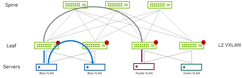
This is the default EVPN routing model. The symmetric model routes and bridges on both the ingress and the egress leaves. This results in bidirectional traffic being able to travel on the same VNI, hence the symmetric name. However, a new specialty transit VNI is used for all routed VXLAN traffic, called the L3VNI. All traffic that must be routed is routed onto the L3VNI, tunneled across the L3 infrastructure, routed off the L3VNI to the appropriate VLAN, and ultimately bridged to the destination. Figure 9 shows bridging and routing in a sample symmetric configuration.
Figure 9 - Symmetric IRB Example
Points to consider:
- The leaf switches only need to host the VLANs and the corresponding VNIs that are located on its rack, as well as the L3VNI and its associated VLAN. The ingress leaf switch doesn’t need to know the destination VNI.
- The ability to host only the local VNIs (plus one extra) helps with scale.
- The configuration is more complex as an extra VXLAN tunnel and VLAN in your network are required.
- Multitenancy requires one L3VNI per VRF, and all switches participating in that VRF must be configured with the same L3VNI. The L3VNI is used by the egress leaf to identify the VRF in which to route the packet.
Scenarios for using Symmetric IRB:
- All use cases of EVPN fabric within the data center except where there is need for a centralized gateway.
- Deployments where the network fabric has non-EVPN routes, such as default routes, static routes, or dynamic routes.
- Large-scale EVPN deployments.
- Widely dispersed VLANs, subnets, or VNIs.
Symmetric VXLAN routing is configured directly on the ToR, using EVPN for both VLAN and VXLAN bridging as well as VXLAN and external routing. Each server is configured on a VLAN and MLAG or MH bond set up between servers and the leaves. Each leaf is configured with an anycast gateway and the servers’ default gateways are pointing towards the corresponding leaf switch IP gateway address. Tenant VNIs (corresponding to the number of VLANs/VXLANs) are bridged to corresponding VLANs. The benefits of this approach include:
- The L2 domain is reduced to the pair of ToRs.
- The aggregation layer is all L3.
- Route scaling and flexibility.
- High availability.
- Overlay flows pass through the same VNI (transit VNI), providing a symmetrical overlay path, making it easy to monitor the flows.
Asymmetric IRB
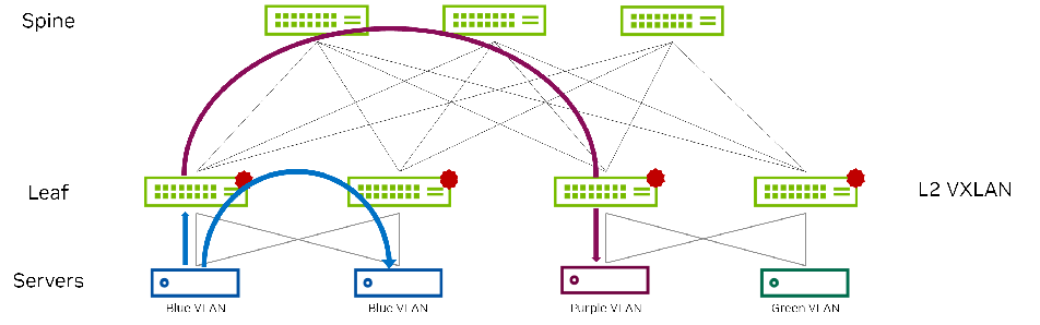
The asymmetric model enables routing and bridging on the VXLAN tunnel ingress, but only bridging on the egress. This results in bidirectional VXLAN traffic traveling on different VNIs in each direction (always the destination VNI) across the routed infrastructure. Figure 10 shows bridging and routing in a sample asymmetric configuration. Even though this is supported by Cumulus Linux, Symmetric IRB is the recommended deployment model.
Figure 10 - Asymmetric IRB Example
Scenarios for using Asymmetric IRB:
- Preferred model for centralized gateway deployment.
- Networks that have switches with legacy ASICs that do not support L3 VXLAN and, therefore, must use centralized gateways.
- Small and medium scale data center deployments.
- Simpler configurations such as all VLANs, subnets, or VNIs configured on all leaves. It’s simpler to configure and doesn’t require extra VNIs to troubleshoot.
Multi-tenancy and VRF
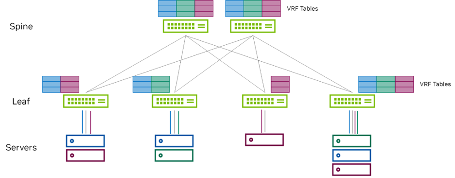
VRF segmentation is used to organize users and devices in groups on a shared network while separating and isolating the different groups. The routing devices on the network create and maintain separate virtual routing and forwarding (VRF) tables for each group. You can use VRFs in the data center to carry multiple isolated traffic streams for multi-tenant environments. Because the multiple routing instances are independent of each other and can use different outgoing interfaces, overlapping IP addresses do not cause any conflict, thus enabling multi-tenancy.
In EVPN, routing is assumed to occur within the context of a VRF. This is true regardless of whether the model is symmetric or asymmetric. The underlay routing table is assumed to be in the default or global routing table, while the overlay routing table is assumed to be in a VRF-specific routing table. It is possible to have asymmetric routing work without the use of VRFs. But VRFs are necessary if the endpoints have to communicate to the external world, because RT-5 advertisements are involved. RT-5 advertisements always occur in the context of a VRF: the L3 VNI signaled in the advertisement. Therefore, to preserve a uniform routing model, always using VRFs with EVPN routing is recommended.
As shown in Figure 11, the servers in a group are placed in one VRF segment and can communicate with each other, but they cannot communicate with users in another VRF segment. If you want to send and receive traffic from one VRF segment to another VRF segment, you must configure route leaking or rely on an external gateway.
Figure 11 - Multi-tenancy using a VRF
Points to consider:
- You must configure the overlay (tenants) in a specific VRF and separate from the underlay, which resides in the default VRF. Cumulus Linux does not support L3 VNI mapping for the default VRF.
- A VRF table can have an IP address, which is a loopback interface for the VRF.
- Cumulus Linux adds the associated rules automatically.
- You can add a default route to avoid skipping across tables when the kernel forwards a packet.
- VRF table names can be a maximum of 15 characters. However, you cannot use the name mgmt; Cumulus Linux uses this name for the management VRF.
- Cumulus Linux supports up to 255 VRFs on the Spectrum 1 switch.
To configure a VRF BLUE and assign a table ID automatically:
nv set vrf BLUE table auto
nv set interface swp1 ip vrf BLUE
nv config apply
BGP Community Lists
You can use community lists to define a BGP community to tag one or more routes. You can then use the communities to apply a route policy on either egress or ingress. The BGP community list can be either standard or expanded. The standard BGP community list is a pair of values (such as 100:100) that you can tag on a specific prefix and advertise to other neighbors or you can apply them on route ingress. An expanded BGP community list takes a regular expression of communities and matches the listed communities.
When the neighbor receives the prefix, it examines the community value and takes action accordingly, such as permitting or denying the community member in the routing policy.BGP EVPN routes can have a set of EVPN extended communities carried in the BGP update message path attribute, and as such, you can use these extended communities for filtering BGP EVPN routes. The EVPN specific information available in extended communities includes, for example, encapsulation type, MAC-mobility information, EVPN split-horizon label information, EVPN ESI split-horizon label, ESI mode, E-tree leaf label, and more.
Here is an example of a standard community list filter:
nv set router policy community-list COMMUNITY1 rule 10 action permit
nv set router policy community-list COMMUNITY1 rule 10 community 100:100
nv config apply
Summarized Route Announcements
In EVPN symmetric routing configurations with VXLAN active-active (MLAG), all EVPN routes advertise with the anycast IP address as the next hop IP address and the anycast MAC address as the router MAC address. In a failure scenario, the switch might forward traffic to a leaf switch that does not have the destination routes. To prevent dropped traffic in this failure scenario, Cumulus Linux enables the Advertise Primary IP address feature by default so that the switch handles the next hop IP address of the VTEP conditionally depending on the route type: host type-2 (MAC and IP advertisement) or type-5 (IP prefix route).
- For host
type-2routes, the anycast IP address is the next hop IP address and the anycast MAC address is the router MAC address. - For
type-5routes, the system IP address (the unique primary loopback IP address of the VTEP) is the next hop IP address and the unique router MAC address of the VTEP is the router MAC address.
Prefix-based Routing
The EVPN type-2 (MAC and IP) advertisement does not support advertising summarized or prefix routes such as /16 or /24 routes. This affects the scalability of the solution.
If you consider a network with edge devices, the edge devices commonly advertise only the default route to border devices. In just about every deployment, the spines and the leaves do not carry the routing table of the external world. They just carry the default route which gets them to the border devices and from there to the edge devices. The default route is 0.0.0.0/0, which has a non-/32 prefix (IPv6 has ::/0 as the default route).
A new route type, type-5 (RT-5) was introduced to support this use case. EVPN in Cumulus Linux supports prefix-based routing using EVPN type-5 (prefix) routes. Type-5 routes (or prefix routes) primarily route to destinations outside of the data center fabric. EVPN prefix routes carry the L3 VNI and router MAC address and follow the symmetric routing model to route to the destination prefix.
Points to consider:
- When connecting to a WAN edge router to reach destinations outside the data center, deploy specific border or exit leaf switches to originate the
type-5routes. - On switches with Spectrum ASICs, centralized routing, symmetric routing, and prefix-based routing only work with Spectrum-A1 and later.
- Configure a per-tenant VXLAN interface that specifies the L3 VNI for the tenant. This VXLAN interface is part of the bridge; router MAC addresses of remote VTEPs install over this interface.
- Configure an SVI (L3 interface) corresponding to the per-tenant VXLAN interface. This attaches to the VRF of the tenant. The remote prefix routes install over this SVI.
- Specify the mapping of the VRF to L3 VNI. This configuration is for the BGP control plane.
Scenarios for using prefix-based routing:
Route to destinations outside of the data center fabric.
To subdivide the data center into multiple pods with full host mobility within a pod but only do prefix-based routing across pods. You can achieve this by only exchanging EVPN
type-5routes across pods. The following example commands configure EVPN to advertisetype-5routes on the leaf:nv set router policy route-map map1 rule 10 match type ipv4 nv set router policy route-map map1 rule 10 match evpn-route-type ip-prefix nv set router policy route-map map1 rule 10 action permit nv set vrf default router bgp address-family ipv4-unicast route-export to-evpn route-map map1 nv config applyTo only exchange EVPN routes carrying a particular VXLAN ID. For example, if data centers or pods within a data center only share certain tenants, you can use a route map to control the EVPN routes exchanged based on the VNI. The following example configures a route map that only advertises EVPN routes from VNI 1000:
nv set router policy route-map map1 rule 10 match evpn-vni 1000
nv set router policy route-map map1 rule 10 action permit
nv config apply
Cumulus Linux supports originating EVPN default
type-5routes. The defaulttype-5route originates from a border (exit) leaf and advertises to all the other leafs within the pod. Any leaf within the pod follows the default route towards the border leaf for all external traffic (towards the Internet or a different pod).nv set vrf RED router bgp address-family ipv4-unicast route-export to-evpn default-route-origination on nv set vrf RED router bgp address-family ipv6-unicast route-export to-evpn default-route-origination on nv config apply
Route Leaking
VRFs are typically used when you want multiple independent routing and forwarding tables. To reach destinations in one VRF from another VRF, Cumulus Linux supports dynamic VRF route leaking. With route leaking, a destination VRF wants to know the routes of a source VRF. As routes come and go in the source VRF, they dynamically leak to the destination VRF through BGP. If BGP learns the routes in the source VRF, you do not need to perform any additional configuration. If OSPF learns the routes in the source VRF, if you configure the routes statically, or you need to reach directly connected networks, you need to redistribute the routes first into BGP (in the source VRF).
You can also use route leaking to reach remote destinations as well as directly connected destinations in another VRF. Multiple VRFs can import routes from a single source VRF and a VRF can import routes from multiple source VRFs. You can use this method when a single VRF provides connectivity to external networks or common services such as DHCP or DNS that are often delivered to multiple tenant VRFs. You can control the routes leaked dynamically across VRFs with a route map.
Because route leaking happens through BGP, the underlying mechanism relies on the BGP constructs of the RD and RTs. However, you do not need to configure these parameters; Cumulus Linux derives them automatically when you enable route leaking between a pair of VRFs.
Points to consider:
- You can assign an interface to only one VRF; Cumulus Linux routes any packets arriving on that interface using the associated VRF routing table.
- You cannot route leak overlapping addresses.
- You can use VRF route leaking with EVPN in a symmetric routing configuration only.
- You cannot use VRF route leaking between the tenant VRF and the default VRF with onlink next hops (BGP unnumbered).
- You cannot reach the loopback address of a VRF (the address assigned to the VRF device) from another VRF.
- You must use the redistribute command in BGP to leak non-BGP routes (connected or static routes); you cannot use the network command.
- Cumulus Linux does not leak routes in the management VRF with the next hop as eth0 or the management interface.
- You can leak routes in a VRF that iBGP or multi-hop eBGP learns even if their next hops become unreachable. NVIDIA recommends route leaking for routes that BGP learns through single-hop eBGP.
- You cannot configure VRF instances of BGP in multiple autonomous systems (AS) or an AS that is not the same as the global AS.
- Do not use the default VRF as a shared service VRF. Create another VRF for shared services, for example service VRF, to simplify configuration and avoid using route maps for filtering.
- To exclude certain prefixes from the import process, configure the prefixes in a route map.
An EVPN symmetric routing configuration has certain limitations when leaking routes between the default VRF and non-default VRFs. The default VRF has routes to VTEP addresses that you cannot leak to any tenant VRFs. If you need to leak routes between the default VRF and a non-default VRF, you must filter out routes to the VTEP addresses to prevent leaking these routes.
Downstream VNI enables you to assign a VNI from a downstream remote VTEP through EVPN routes instead of configuring L3 VNIs globally across the network. To configure a downstream VNI, you configure tenant VRFs as usual; however, to configure the desired route leaking, you define a route target import and, or export statement.
Scenarios for using route leaking:
- To make a service, such as a firewall available to multiple VRFs.
- To enable routing to external networks or the Internet for multiple VRFs, where the external network itself is reachable through a specific VRF.
In the following example commands, routes in the BGP routing table of VRF BLUE dynamically leak into VRF RED.
nv set vrf RED router bgp address-family ipv4-unicast route-import from-vrf list BLUE
nv config apply
The following example configures a route map to match the source protocol BGP and imports the routes from VRF BLUE to VRF RED. For the imported routes, the community is 11:11 in VRF RED.
nv set vrf RED router bgp address-family ipv4-unicast route-import from-vrf list BLUE
nv set router policy route-map BLUEtoRED rule 10 match type ipv4
nv set router policy route-map BLUEtoRED rule 10 match source-protocol bgp
nv set router policy route-map BLUEtoRED rule 10 action permit
nv set router policy route-map BLUEtoRED rule 10 set community 11:11
nv set vrf RED router bgp address-family ipv4-unicast route-import from-vrf route-map BLUEtoRED
nv config apply
ARP Suppression
ARP suppression with EVPN allows a VTEP to suppress ARP flooding over VXLAN tunnels as much as possible. It helps reduce broadcast traffic by using EVPN to proxy responses to ARP requests directly to clients from the ToR VTEP. A local proxy handles ARP requests from locally attached hosts for remote hosts. ARP suppression is for IPv4; ND suppression is for IPv6.
Cumulus Linux enables ARP and ND suppression by default on all VNIs to reduce ARP and ND packet flooding over VXLAN tunnels; however, you must configure L3 interfaces (SVIs) for ARP and ND suppression to work with EVPN.
Without ARP suppression, all ARP requests are broadcast throughout the entire VXLAN fabric, sent to every VTEP that has a VNI for the network. With ARP suppression enabled, MAC addresses learned over EVPN are passed down to the ARP control plane. The leaf switch, which acts as the VTEP, responds directly back to the ARP requester through a proxy ARP reply.
Because the IP-to-MAC mappings are already communicated through the VXLAN control plane using EVPN type-2 messages, implementing ARP suppression enables optimization for faster resolution of the overlay control plane. It also reduces the amount of broadcast traffic in the fabric, as ARP suppression reduces the need for flooding ARP requests to every VTEP in the VXLAN infrastructure.
Points to consider:
- You can only use ND suppression on Spectrum_A1 and above.
- Cumulus Linux enables ARP suppression by default. However, in a VXLAN active-active (MLAG) configuration, if the switch does not suppress ARPs, the control plane does not synchronize neighbor entries between the two switches operating in active-active mode. You do not see any impact on forwarding.
- In an EVPN centralized routing configuration, where the L2 network extends beyond VTEPs, (for example, a host with bridges), the gateway MAC address does not refresh in the network when ARP suppression exists on the gateway. To work around this issue, disable ARP suppression on the centralized gateway.
EVPN for BUM Traffic
The common terminology to refer to flooded packets is Broadcast, unknown Unicast, and unknown Multicast, or BUM, packets. EVPN provides two choices for packet forwarding of BUM packets: ingress replication and L3 underlay multicast.
Ingress replication is called head-end-replication which performs unicast delivery of VXLAN encapsulated packets across remote VTEPs. In unicast replication, the source VTEP delivers the same data to every other remote VTEP. Whereas in multicast replication, all the VTEPs join at a rendezvous point (preferred is PIM-SM RP) to receive VXLAN encapsulated data. This enables multicast to have a lower overhead and faster delivery compared to unicast; however, multicast is less secure.
Ingress Replication/Head-end-replication
In ingress replication, the ingress NVE sends multiple copies of a packet, one for each egress NVE interested in the virtual network.
Benefits of this model include:
- It keeps the underlay simple. The underlay needs to provide only IP unicast routing to support network virtualization.
- It is easy to configure - there is no additional configuration required. The replication list is automatically built from the BGP EVPN RT-3 (carrying the VNIs of interest to a VTEP) messages without any further intervention from the user.
- This makes the solution more robust, because the chances of human error are reduced significantly.
Disadvantages of this model include:
- The replication bandwidth required from the underlay can be high, especially if there are lots of BUM packets.
If the number of NVEs to replicate to is not large and the amount of BUM traffic is low, this approach works quite well. Even if the number of NVEs to replicate is higher but the amount of traffic is low, this method works quite well.
Cumulus Linux uses Head End Replication by default with EVPN multihoming.
Multicast Replication
By using multicast, the ingress NVE does not have to send a separate copy for each egress NVE. The most commonly used multicast routing protocol is called PIM. PIM-SM is used for optimizing flooded traffic in a network with EVPN-MH.
Benefits of this model include:
- It is possible to handle a large volume of BUM packets or even well-known multicast packets efficiently.
Disadvantages of this model include:
- This might become difficult to manage. In this model, in addition to providing unicast routing support, the underlay must also provide multicast routing support.
- PIM-SM requires additional protocols, such as Session Discovery Protocol (SDP), for a reliable deployment.
- To ensure that for every virtual network only the associated NVEs get the packet, each virtual network must be in its own multicast group. But this results in far too many multicast groups to scale well. So, you must now manually map all of the virtual networks into a smaller number of multicast groups. This in turn leads to some NVEs receiving BUM packets for virtual networks in which they have no interest.
- Mapping a virtual network to a multicast group also adds significant configuration complexity. You must configure the mapping of a virtual network to a multicast group on every single NVE. There is no simple way to ensure that this configuration is consistent and correct across all the NVEs.
Figure 12 shows an EVPN-PIM configuration, where underlay multicast distributes BUM traffic.
Figure 12 – EVPN-PIM for BUM Traffic
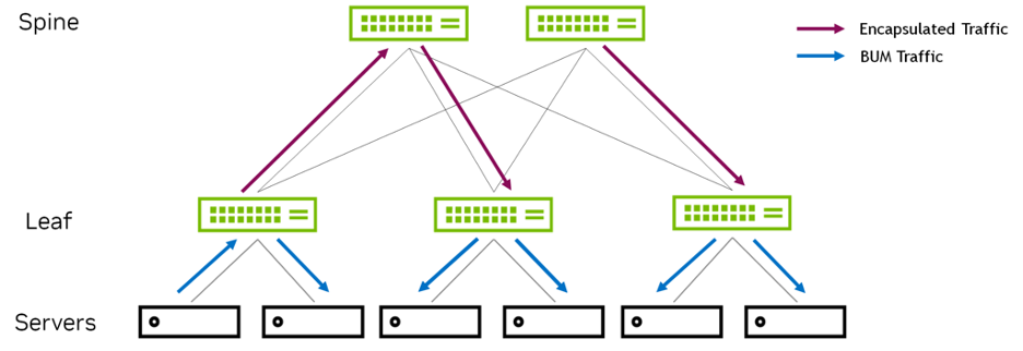
By default, the VTEP floods all BUM packets (such as ARP, NS, or DHCP) it receives to all interfaces (except for the incoming interface) and to all VXLAN tunnel interfaces in the same broadcast domain. When the switch receives such packets on a VXLAN tunnel interface, it floods the packets to all interfaces in the packet’s broadcast domain. For PIM-SM, type-3 routes do not result in any forwarding entries. Cumulus Linux does not advertise type-3 routes for an L2 VNI when BUM mode for that VNI is PIM-SM.
Dropping BUM packets
BUM packets are considered by many network administrators to be a cheap way to launch a Distributed Denial-of-Service (DDoS) attack on the network. By sending packets to addresses that might never be seen by the network, less network bandwidth is available for legitimate traffic. Such packets can deluge end hosts in that virtual network and cause them to fail because the system is very busy coping with BUM packets.
Dropping BUM packets implies that after we hear from an endpoint, its MAC address is communicated to all the other nodes via BGP. Therefore, there is really no need to flood these packets.
You can disable BUM flooding over VXLAN tunnels so that EVPN does not advertise type-3 routes for each local VNI and stops taking action on received type-3 routes.
Disabling BUM flooding is useful in a deployment with a controller or orchestrator, where the switch is pre-provisioned and there is no need to flood any ARP, NS, or DHCP packets.
nv set nve vxlan flooding enable off
nv config apply
The main disadvantage of this approach is possible communication breakdown with traffic meant for silent servers. Silent servers are increasingly rare so this may not be a problem for your network. Dropping BUM packets is a local configuration setting, not advertised to other neighbors.