Introduction
Overview
In the current era of networking, network simplicity, agility and scale are essential. In the past, applications were designed to function within the same layer 2 (L2) domain. This caused problems because protocols like Spanning Tree (STP) are fragile and noisy. Layer 3 (L3) protocols are increasingly popular as they can scale more easily and efficiently.
Ethernet VPN (EVPN) is a technology that connects L2 network segments separated by an L3 network. It is an extension to Border Gateway Protocol (BGP) that enables the network to carry endpoint reachability information such as L2 MAC addresses and L3 IP addresses.
In the Data Center, EVPN enables optimal east-west and south-north traffic forwarding. It supports Integrating Routing and Bridging for routing between subnets routing and multi-tenancy. In the virtualization scenario, it also supports MAC mobility, so virtual machines can be moved within or across racks. As EVPN is multi-transport, it can run over VXLAN and enables scalable service fabrics.
Key Use Cases
L2 and L3 VPN for tenancy. You can choose to segment your networks at L2, L3, or both. By carrying L2 and L3 endpoint reachability information, EVPN supports integrated bridging and routing in overlay networks.
Scaling out the access layer
a. Active-active L2 and EVPN multihoming at the access is critical for high availability.
b. Optimal forwarding of east-west and north-south traffic.
c. Minimizes flooding within the network through protocol-based host MAC, and IPv4 and IPv6 route distribution, additionally providing early Address Resolution Protocol (ARP) termination at the local access switches.
d. Allows full network bandwidth utilization by running VXLAN at the access layer and eliminating the need to run STP.
Extending services beyond a single data center. VXLAN EVPN enabled the industry to use new data center deployment approaches and optimized ingress routing. As the EVPN control plane evolves, L2 extensions can not only cross physical rack boundaries but also stretch across data centers.
Intended Audience
This document is intended for networking professionals and discusses EVPN-VXLAN cloud data center architecture concepts and tools, and the best practices to consider for deployment.
The concepts, features, and commands in this document are supported in Cumulus Linux 5.3 and later.
Topology
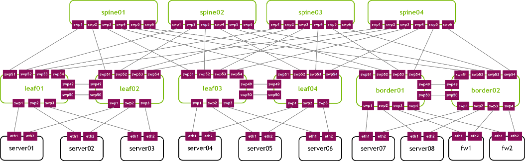
The following topology is used throughout the document.
Basic Terminology
| Leaf | Also referred to as an access switch, where servers connect to the network. Servers and storage connect to leaf switches that aggregate the network traffic. |
| Spine | Also referred to as an aggregation switch, end-of-row switch, or distribution switch, where leaf switches connect into the spine, forming the access layer that delivers network connection points for servers. |
| Border leaf | A leaf that connects external services, such as firewalls, load balancers and internet routers, for north-south traffic typically. This acts as a demarcation zone between the underlying fabric and the outside world. The border leaf is responsible for announcing the prefix of the fabric to the outside world and determining how to join the internet and other data centers. |
| Super spine | Sometimes referred to as a spine aggregation switch, end-of-row switch, or data center core switch. |
Common Data Center Architectures
Over the past decade, data centers have increased in size; they require applications that are vastly different from the traditional client–server applications and need much faster deployment speeds (seconds instead of days). This changes how networks must be designed and deployed. Data centers now have a growing demand for server-to-server communication at high scale and high resilience.
The traditional standard access, aggregation, and core layer architecture was suitable for north-to-south traffic flows that go in and out of a data center. This architecture was based on the L2 switching model. However, this model surfaced many disadvantages to network redundancy, scale, lack of TTL field in the L2 frames, and reliability in contrast to the robust L3 network model. In addition, many applications operating inside of the data center required cross communication and the ability to talk amongst themselves. A cleaner design is to move from the L2 switching model to IP and network routing protocols.
The cloud native data center infrastructure pioneers picked a network topology called CLOS to fashion their data centers. Clos networks are named after their inventor, Charles Clos. The design allows you to build a network that is not limited by the scale of a single unit but can scale to a number of tiers. However, two tiers are used in a majority of the use cases.
Two-Tier Clos Architecture (Leaf-Spine)
Figure 1 shows the most common Clos two-tier topology. The green nodes represent the switches and the black nodes the servers. There are two layers of switches: spine and leaf, therefore, the topology is commonly called a leaf-spine topology.
Figure 1 - Two-Tier CLOS Topology
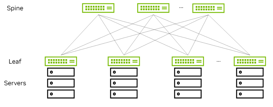
The spine nodes connect the leaf nodes with one another and the leaf nodes connect the servers to the network. Every leaf is connected to every spine node.
This topology produces a high-capacity network because there are more than two paths between any two servers. Adding more spines or multiple links to the spine increases the available bandwidth between leaves, thanks to equal-cost multipath (ECMP).
The endpoints are all connected to leaves and the spines merely act as connectors. In this model, the functionality is pushed out to the edges instead of pulled into the spines. This model of scaling is called a scale-out model.
Typically, servers are interconnected to the leaf through lower-speed links and the switches are interconnected by higher-speed links. A common deployment is to interconnect servers to leaves through 25 Gbps links, while interconnecting switches with one another through 100 Gbps links. In AI/ML environments, you can also have higher bandwidth servers with 50/100G network interface cards and 200/400G interconnects.