Layer 1 Data Center Cheat Sheet
Your reference sheet for going web-scale with NVIDIA Spectrum switches and LinkX transceivers.
With NVIDIA Spectrum switches with the LinkX cables and optics, you can build a web-scale scalable and efficient data center. With Cumulus Linux Network OS on top, you can leverage the data center automation available to the largest data center operators in the world.
You have the ability to:
- Customize your network applications
- Automate your configurations
- Choose whatever form-factor hardware you want – based on your budget and your needs
- Build a web-scale data center like the world’s largest operators at a fraction of the cost
Web-scale networking is the new, modern way to build your network. It gives you access to intelligent software, it’s open and modular, and it enables you to automate and scale with ease.
This short guide provides a reference to NVIDIA data center components. It includes NVIDIA Ethernet Spectrum switches, LinkX Layer 1 products and most-common data center topologies.
In addition, here you can find the most common layer 1 terminology and standards explained.
Data Center Terminology
Clos - A multi-stage network architecture that optimizes resource allocation for bandwidth. Named after Charles Clos.ToR - Top of Rack switch, where servers connect to the network.Leaf - Also referred to as a ToR or Access Switch. Used typically when referring to Spine-Leaf or Clos topology.Exit-Leaf - A leaf connected to services outside the data center, including firewalls, load balancers and internet routers.Spine - Also referred to as an aggregation switch, end-of-row switch or distribution switch. Typically referred to as a Spine switch in a Spine-Leaf or Clos topology.Super-Spine - Sometimes referred to as a spine aggregation switch, end-of-row switch or data center core switch. Typically referred to as a Super-Spine switch in a Three-tier Clos topology.MLAG - Multi-Chassis Link Aggregation. Ability for a pair of switches to act redundantly in an active-active architecture and appear as a single, logical switch.Peerlink - Link or bonded links used to connect two switches in an MLAG pair.ECMP - Equal-Cost Multi-Path routing. Allows load sharing across multiple routed paths.Layer 3 Fabric - Sometimes called a routed fabric. A network with layer 3 routing between leaf and spine layers. Layer 3 fabric allows ECMP to enhance the leaf-spine bandwidth.OOB - Out of Band Management. A lower speed (generally 1Gbps or less) network dedicated to infrastructure management, outside of the high-speed leaf and spine network. Out of Band Management is also the name of the 1g switch management interface.POD - A unit of network, storage and compute that work together to deliver networking services. POD is a repeatable design pattern which provides scalable and easier to manage data centers.
Common Data Center Architectures
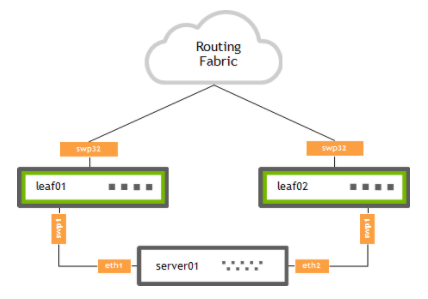
Two-Tier Clos Architecture (Leaf-Spine)
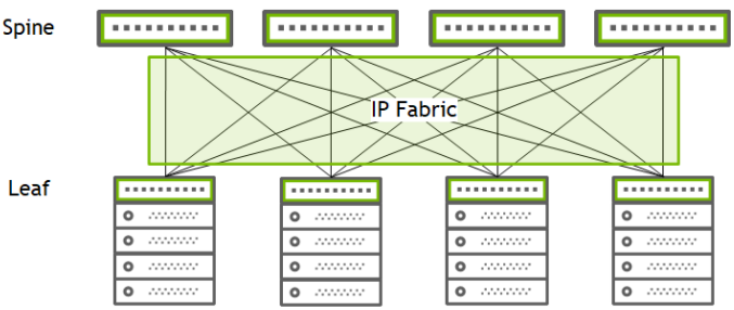
A two-tier Clos or leaf and spine network connects each leaf to every spine. There are no connections between spines. All traffic traverses only one spine switch. In this data center architecture, the two switch levels are connected using routing fabric. The spine layer is built with three or more switches. By using a routed environment between the two tiers, this eliminates the need of MLAG on the spines and allows for equal cost multipath (ECMP) load sharing between all spines. With BGP-EVPN, MLAG can be eliminated by using EVPN-Multihoming (EVPN-MH). This provides dual-attached server redundancy while removing the complexities of MLAG.
Three-Tier Clos Architecture (Leaf-Spine-Super Spine)
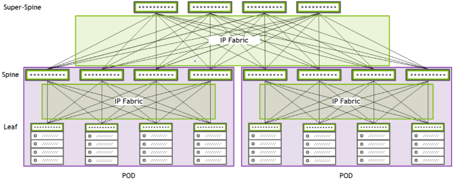
For larger networks, leaf switches can be incrementally added and aggregated with the spines layer within a single POD.To scale-up the data center and create pods. Another layer of switches, labeled super-spines, can be used to aggregate each pod Spine layer. This architecture is the Three-Tier Clos network.
Common Host to ToR (Leaf) Network Connectivity Types
MLAG
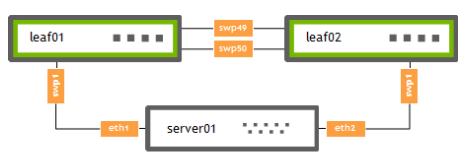
MLAG is when two switches can create a single LACP or static bond despite coming from two independent devices. VRR (Virtual Router-Redundancy) enables a pair of switches to act as a single gateway for High Availability (HA) and Active-Active server links.
EVPN Multihoming (EVPN-MH)
EVPN Multihoming (EVPN-MH) is a standards-based replacement for the proprietary MLAG protocol in data center deployments. It provides an all-active server connectivity without the need for peerlinks between ToR switches.The fact that EVPN-MH is a standards-based protocol, multi-vendor interoperability with a single BGP-EVPN control plane is possible. This protocol allows easier data center deployments without the need of understanding and using proprietary protocols.
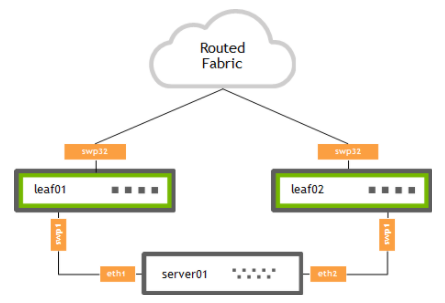
Redistribute Neighbor
Redistribute neighbor daemon dynamically monitors ARP entries to redistribute these IP addresses into the fabric. Redistribute neighbor is useful when MLAG and EVPN are not viable alternatives for server connectivity.
NVIDIA Spectrum Families Data Center Switches
This section includes all NVIDIA Spectrum switches form-factors used in data center deployments
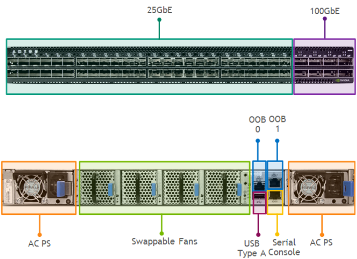
Spectrum 1RU Half-width ToR
- Switching Capacity: 1.7Tbps (1.26Bpps)
- Ports: 18x25GbE SFP28 (NRZ) + 4x100GbE QSFP28 (NRZ)
Maximum Ports Power Support
- SFP28 Ports 1-2,17-18 up to 2.5W
- SFP28 Ports 3-16 up to 1.5W
- QSFP28 Ports 19-22 up to 4.5W
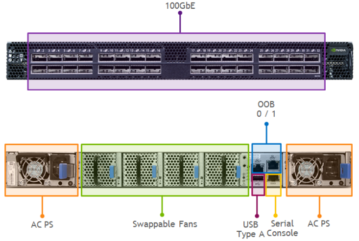
Spectrum 1RU Half-width ToR
- Switching Capacity: 3.2Tbps (2.38Bpps)
- Ports: 16x100GbE QSFP28 (NRZ)
Maximum Ports Power Support
- QSFP28 Ports 1-2,15-16 up to 4.5W
- QSFP28 Ports 3-14 up to 3.5W
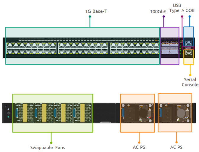
Spectrum 1RU 1GBase-T Management Switch
- Switching Capacity: 448GBps
- Ports: 48x1GBase-T* RJ45 up to 100m (CAT5E/6) + 4x100GbE QSFP28 (NRZ)
*Supports 10/100MBase-T
Maximum Ports Power Support
- QSFP28 Ports 49-52 up to 5W
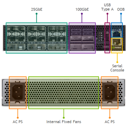
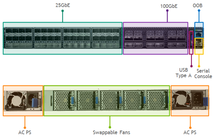
Spectrum 1RU ToR
- Switching Capacity: 3.2Tbps (2.38Bpps)
- Ports: 48x25GbE SFP28 (NRZ) + 8x100GbE QSFP28 (NRZ)
Maximum Ports Power Support
- SFP28 Ports 1-2,47-48 up to 4.5W
- SFP28 Ports 3-46 ip to 1.5W
- QSFP28 Ports 49-50,55-56 up to 5.0W
- QSFP28 Ports 51-54 up to 3.5W
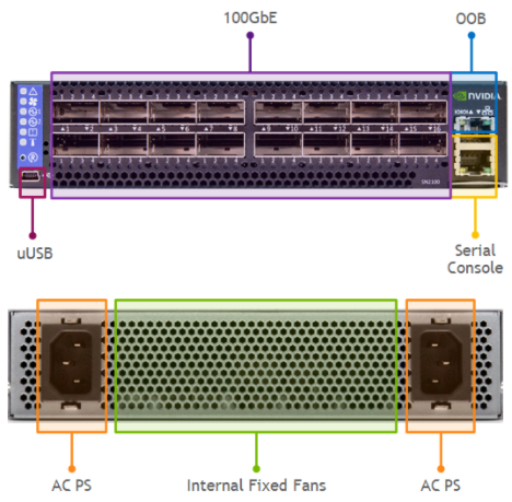
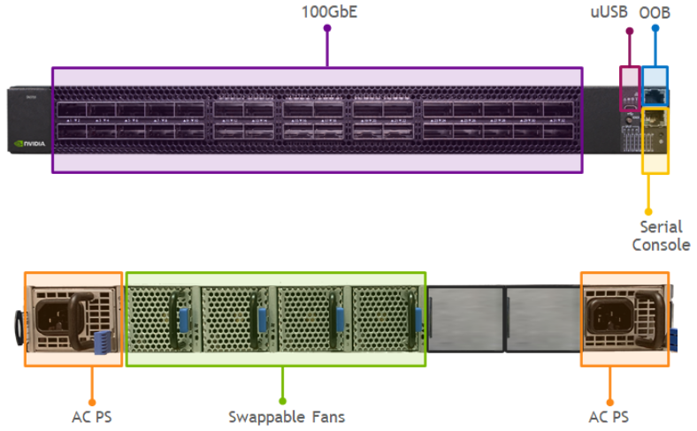
Spectrum 1RU ToR/Spine
- Switching Capacity: 6.4Tbps (4.76Bpps)
- Ports: 32x100GbE QSFP28 (NRZ)
Maximum Ports Power Support
- QSFP28 Ports 1-2,31-32 up to 5.0W
- QSFP28 Ports 3-30 up to 3.5W
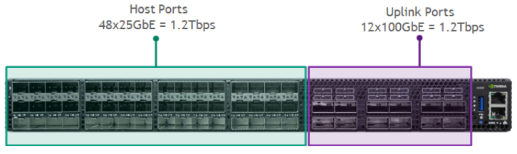
Spectrum-2 1RU ToR
- Switching Capacity: 4.8Tbps (3.58Bpps)
- Ports: 48x25G SFP28 (NRZ) + 12x100GbE QSFP28 (NRZ)
Maximum Ports Power Support
- SFP28 Ports 1-6 up to 2.5W
- SFP28 Ports 7-48 ip to 1.5W
- QSFP28 Ports 49-52,54,56,58,60 up to 3.5W
- QSFP28 Ports 53,55,57,59 up to 5.0W
Spectrum-2 1RU ToR/Spine
- Switching Capacity: 6.4Tbps (4.76Bpps)
- Ports: 32x100G QSFP28 (NRZ)
Maximum Ports Power Support
- QSFP28 Ports 1-2,31-32 up to 5.0W
- QSFP28 Ports 3-30 up to 3.5W
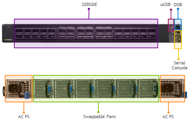
Spectrum-2 1RU ToR/Spine
- Switching Capacity: 12.8Tbps (8.33Bpps)
- Ports: 32x200G QSFP56 (PAM4)
Maximum Ports Power Support
- QSFP56 Ports 1-32 up to 5.0W
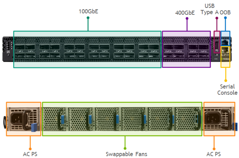
Spectrum-3 1RU ToR
- Switching Capacity: 8.0Tbps
- Ports: 24x200G QSFP56-DD (48x100GbE NRZ) + 8x400GbE QSFP56-DD (PAM4)
Maximum Ports Power Support
- QSFP56-DD Ports 1-32 up to 12.0W
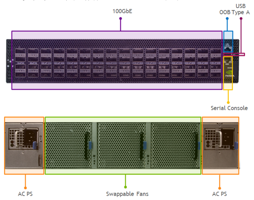
Spectrum-3 2RU Spine/Super-Spine
- Switching Capacity: 12.8Tbps (8.4Bpps)
- Ports: 64x100GbE QSFP28 (NRZ)
Maximum Ports Power Support
- QSFP28 Ports 1-48 up to 3.5W
- QSFP28 Ports 49-64 up to 5.0W
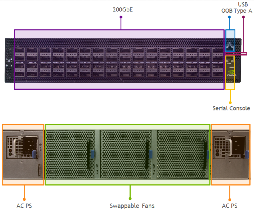
Spectrum-3 2RU Spine/Super-Spine
- Switching Capacity: 25.6Tbps (8.4Bpps)
- Ports: 64x200GbE QSFP56 (PAM4)
Maximum Ports Power Support
- QSFP56 Ports 1-64 up to 5.0W
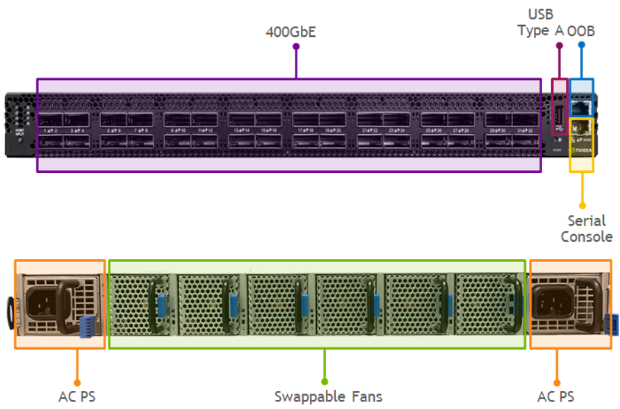
Spectrum-3 1RU Spine/Super-Spine
- Switching Capacity: 25.6Tbps (8.4Bpps)
- Ports: 32x400GbE QSFP56-DD (PAM4)
Maximum Ports Power Support
- QSFP56-DD Ports 1-32 up to 12.0W (in C2P airflow models)
Breakout Ports Configuration
NVIDIA Spectrum platforms provide flexible port breakout options to allow more efficient switch-to-switch or host-to-switch cabling by fewer ports/cables utilization while delivering the same performance with the same form-factor switches.
This platform has 4 QSFP28 (NRZ) splittable ports.
All QSFP28 (100GbE) ports can be split into 4xSFP28 (4x25GbE) or 2xQSFP28 (2x50GbE).
This platform has 16 QSFP28 (NRZ) splittable ports.
All QSFP28 (100GbE) ports can be split into 4xSFP28 (4x25GbE) or 2xQSFP28 (2x50GbE).
This platform has 4 QSFP28 (NRZ) splittable ports.
All QSFP28 (100GbE) ports can be split into 4xSFP28 (4x25GbE) or 2xQSFP28 (2x50GbE).
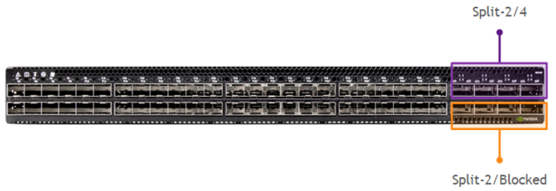
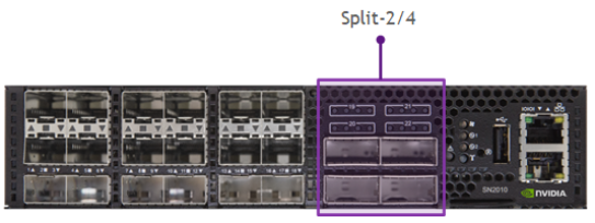
This platform has 4 or 8 QSFP28 (NRZ) splittable ports.
The top QSFP28 (100GbE) ports can be split into 4xSFP28 (4x25GbE) each. But, in that case, the bottom QSFP28 ports are blocked.
All QSFP28 ports are splittable into 2xQSFP28 (2x50GbE) without blocking ports.
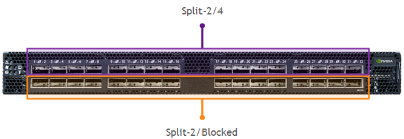
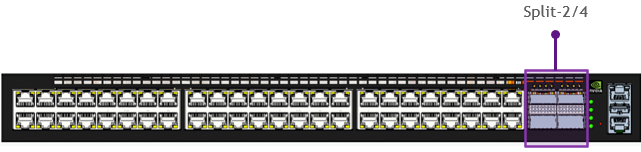
This platform has 16 or 32 QSFP28 (NRZ) splittable ports.
The top QSFP28 (100GbE) ports can be split into 4xSFP28 (10/25GbE) each. But, in that case, the bottom ports are blocked.
All QSFP28 ports are splittable into 2xQSFP (2x50GbE) without blocking ports.
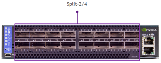
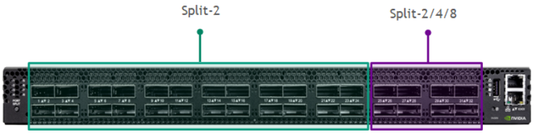
This platform has 12 QSFP28 (NRZ) splittable ports.
All QSFP28 (100GbE) ports can be split into 4xSFP28 (4x25GbE) or 2xQSFP28 (2x50GbE).

This platform has 32 QSFP28 (NRZ) splittable ports.
All QSFP28 (100GbE) ports can be split into 4xSFP28 (4x25GbE) or 2xQSFP28 (2x50GbE).
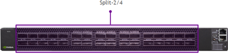
This platform has 32 QSFP56 (PAM4) splittable ports.
All QSFP56 (200GbE) ports can be split into 4xSFP56 (4x50GbE) or 2xQSFP56 (2x100GbE).
All splitted/non-splitted ports also support lower 10/25/40GbE speeds. For lower speeds, PAM4 is automatically converted to NRZ encoding.
This platform has 24 QSFP56-DD (NRZ) and 8 QSFP56-DD (PAM4) splittable ports.
All QSFP56-DD ports are splittable. The first 24 (2x200GbE PAM4) ports can be split into 2xQSFP28 (2x100GbE NRZ) only.The last 8 (400GbE PAM4) ports can be split into 2xQSFP56 (2x200GbE), 4xQSFP56 (4x100GbE) or 8xSFP56 (8x50GbE).
All splitted/non-splitted ports also support lower 10/25/40GbE speeds. For lower speeds, PAM4 is automatically converted to NRZ encoding.

This platform has 32 or 64 QSFP28 (NRZ) splittable ports.
Each QSFP28 (100GbE) port can be split into 4xSFP28 (4x25GbE). But, in this case, the port above or below it will be blocked. All ports are splittable into 2xQSFP28 (2x50GbE) without blocking ports.
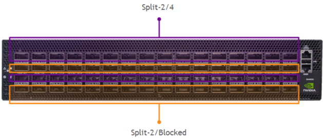
This platform has 32 or 64 QSFP56 (PAM4) splittable ports.
Each QSFP56 (200GbE) port can be split into 4xSFP28 (4x25GbE) or 4xSFP56 (4x50GbE). But, in this case, the port above or below it will be blocked. All ports are splittable into 2xSFP56 (2x50GbE) or 2xQSFP56 (2x100GbE) without blocking ports.
All splitted/non-splitted ports also support lower 10/25/40GbE speeds. For lower speeds, PAM4 is automatically converted to NRZ encoding.
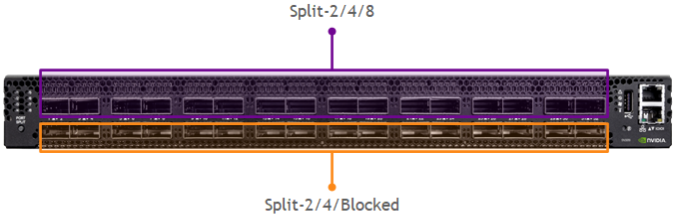
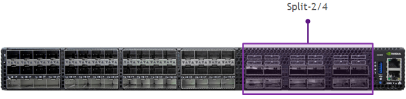
This platform has 16 or 32 QSFP56-DD (PAM4) splittable ports.
Each QSFP56-DD (400GbE) port can be split into 8xSFP56 (8x50GbE). But, in this case, the port above or below it will be blocked. All ports are splittable into 2xQSFP56 (2x200GbE) or 4xQSFP56 (4x100GbE) without blocking ports.
All splitted/non-splitted ports also support lower 10/25/40GbE speeds. For lower speeds, PAM4 is automatically converted to NRZ encoding.
Check out all platform’s speeds and breakout options in Switch Port Attributes page.
A single SFP (10/25/50G) transceiver can be used in a QSFP (100/200/400G) port with the help of QSFP-to-SFP Adapter (QSA). The port speed should be set to the SFP speed by “nv set interface <interface> link speed <speed>” command. Do not configure this port as a breakout port.
Oversubscription Calculation
Oversubscription is the difference in host bandwidth (downlinks) vs. network capacity (uplinks). These calculations are shown from the point of view of a ToR Switch. A 1:1 oversubscription ratio ensures no network bottlenecks, but may result in excess capacity during non-peak times.The ideal design tries to approach 1:1 oversubscription but entirely depends on the applications and capacity needed by the administrator.
Spectrum portfolio offers both blocking and non-blocking ToR switches.
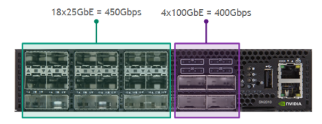
This ToR switch has 450Gbps downlinks to servers and 400Gbps uplinks to the network which is represented as a 1.125:1 oversubscription ratio (450/400=1.125).
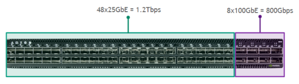
This ToR switch has 1.2Tbps downlinks to servers and 800Gbps uplinks to the network which is represented as a 1.5:1 oversubscription ratio (1200/800=1.5).
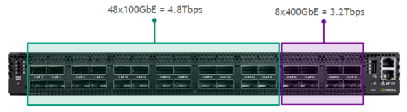
This ToR switch has 4.8Tbps downlinks to servers and 3.2Tbps uplinks to the network which is represented as a 1.5:1 oversubscription ratio (4800/3200=1.5).
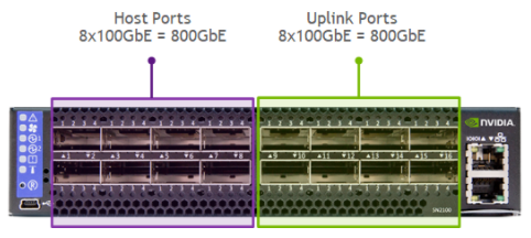
Oversubscription Ratio: 800GbE/800GbE = 1, which is represented at 1:1 oversubscription.This model’s for factor is ½ width RU, thus two can be placed in 1RU and provide 1:1 oversubscription ratio with layer 2 redundancy (MLAG).
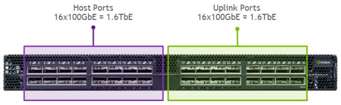
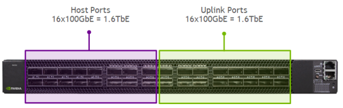
Oversubscription Ratio: 1600GbE/1600GbE = 1, which is represented at 1:1 oversubscription.
Oversubscription Ratio: 1200GbE/1200GbE = 1, which is represented at 1:1 oversubscription.
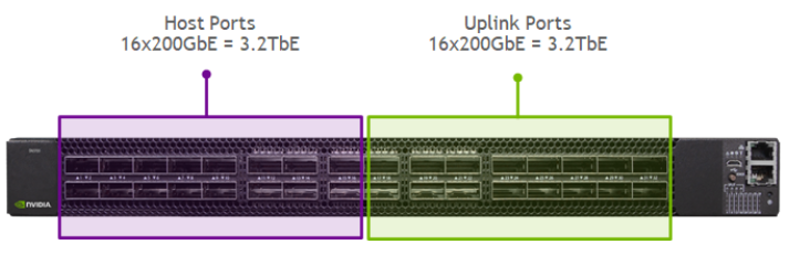
Oversubscription Ratio: 1600GbE/1600GbE = 1, which is represented at 1:1 oversubscription.
Oversubscription Ratio: 3200GbE/3200GbE = 1, which is represented at 1:1 oversubscription.
Using higher capacity switches (Spine/Super-Spines) as ToR switches, can provide 1:1 oversubscription as well.
Ethernet Optics and Cables
This section includes NVIDIA LinkX optics and cabling terminology used within data centers. LinkX portfolio offers a variety of DAC, AOC cables and optical transceivers to deliver the most efficient data center elements interconnect with the best performance.
Transceivers Modulation Scheme
100GbE and below use Non-Return to Zero (NRZ) modulation scheme to transmit traffic. 200GbE and above transitioned into Pulse Amplitude Modulation 4-levels (PAM4) modulation scheme. PAM4 doubles the NRZ rates while keeping the same 25GHz clock and low cost connectors.
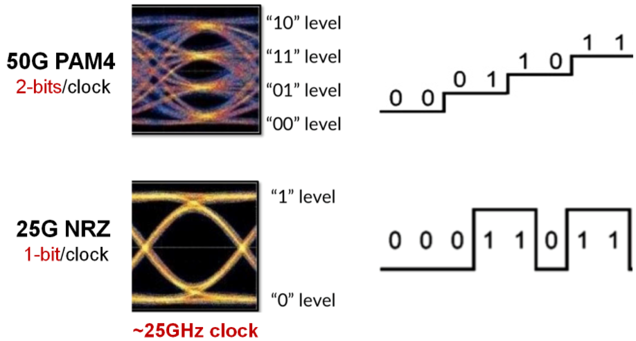
The NRZ and PAM4 signaling are not compatible with each other as NRZ is based on 1-bit/clock and PAM4 on 2-bits/clock. To connect two sides with different modulation types, a special converter is needed. This converter is called “gearbox” and it is placed inside a transceiver or a switch system. NVIDIA offers optical transceivers which include the gearbox inside and allows these types of connection (e.g. 8x50G PAM4 to 4x100G NRZ).
NRZ Modulation Speeds use clockings that are multiples of 1,10 or 25G.The following interface configurations are supported with NRZ:
- 1GbE (1x1G)
- 10GbE (1x10G)
- 25GbE (1x25G)
- 40GbE (4x10G)
- 50GbE (2x25G)
- 100GbE (4x25G)
PAM4 Modulation Speeds - use clockings that are multiples of 50 or 100g.The following interface configurations are supported with PAM4 (above 100G):
- 200GbE (4x50G)
- 400GbE (8x50G or 4x100G)
- 800GbE (8x100G)
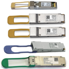
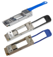
Transceivers Form Factors
SFP+ - Small Form-factor Pluggable Plus. SFP+ supports one channel of 10 Gigabit Ethernet using NRZ signaling.
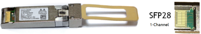
SFP28 - Small Form-factor Pluggable 28. SFP28 supports one channel of 25 Gigabit Ethernet using NRZ signaling.
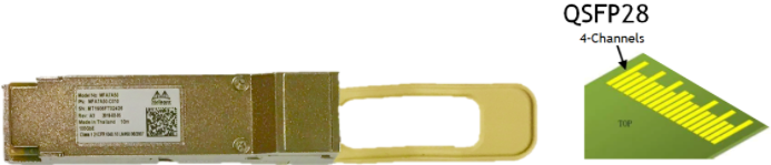
QSFP28 - Quad Small Form-factor Pluggable 28. QSFP28 supports four channels of 25 Gigabit Ethernet using NRZ signaling (4x25=100Gbp/s).
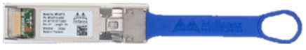
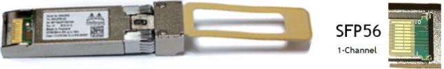
SFP56 - Small Form-factor Pluggable 56. SFP56 supports one channel of 50 Gigabit Ethernet using PAM4 signaling.
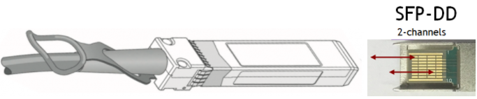
SFP-DD - Small Form-factor Pluggable Double Density. SFP-DD supports two channels for 50 Gigabit Ethernet links using PAM4 signaling (2x50=100Gbp/s).
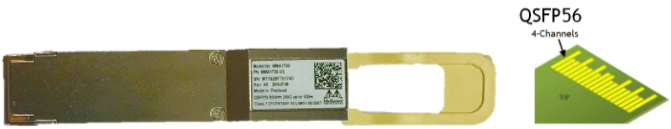
QSFP56 - Quad Small Form-factor Pluggable 56. QSFP56 supports four channels of 50 Gigabit Ethernet using PAM4 signaling (4x50=200Gbp/s).
QSFP56-DD - Quad Small Form-factor Pluggable Double Density. QSFP56-DD supports eight channels of 50 Gigabit Ethernet links using PAM4 signaling (8x50=400Gbp/s).

Transceiver Speed Supportability
This table shows the speeds each transceiver type supports:
| Speed | SFP+ | SFP28 | SFP56 | QSFP+ | QSFP28 | QSFP56 | QSFP56-DD |
|---|---|---|---|---|---|---|---|
| 1G | |||||||
| 10G | |||||||
| 25G | |||||||
| 40G | |||||||
| 50G | |||||||
| 100G | |||||||
| 200G | |||||||
| 400G |
Cables and Transceivers Types
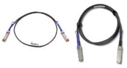
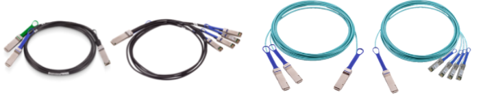
DAC - Direct Attached Copper. A type of cable that consists of a transceiver and cable combined together.
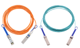
AOC - Active Optical Cable. A type of cable similar to a DAC where the transceiver and cable are combined except it uses multimode or single-mode fiber instead of copper. AOC provides longer distances and lighter weights when compared to DAC.
Breakouts (Splitters) - Used to breakout a single QSFP port to two or four SFP ports. Both AOC and DAC cables can be designed with splitters. Both types support all available port speeds and encodings including NRZ to PAM4 translation e.g. 100GbE to 4x25GbE NRZ, 200GbE to 4x25GbE PAM4.
Optical Transceiver - Uses lasers to transmit and receive data over a pluggable optical fiber. The fiber can be multi-mode or single-mode depending on the transceiver type.
QSA - QSFP to SFP Adapter. This Adapter is used to convert any QSFP port to SFP.There are a few types of QSAs, each suited to different SFP/QSFP types:
- QSA+ - 40GbE QSFP+ to 10GbE SFP+ (NRZ)
- QSA28 - 100GbE QSFP28 to 25GbE SFP28 (NRZ)
- QSA56 - 200GbE QSFP28 to 50GbE SFP56 (PAM4)
Optical Transceivers Types
Short Reach (SR) - This includes SR, SR4 and SR8 Short Reach transceivers up to 100m. Using multi-mode fiber SR uses a single-channel for 10/25/50GbE links. SR4 uses four-channels and is used for 40/100/200GbE links. SR4 can operate as a single (four-channel) link (e.g., 100G PAM4) or as four separate links (e.g., 4x10G PAM4 breakout). 400GbE speeds are based on SR8 multi-mode transceivers.Note: 40GbE-SR4 can reach up to 150m.
Parallel Single Mode (PSM4) - Parallel Single Mode transceivers up to 2km. PSM4 uses a 1310nm laser on single-mode fiber. It uses four-channels and is used for 100/200GbE links.
CWDM4 (FR4) - Coarse Wavelength Division Multiplexing or Far Range transceivers up to 2km. They use 1310nm lasers on single-mode fiber.
SWDM4 - Short Wavelength Division Multiplexing transceivers up to 100m. They use 850nm lasers on multi-mode fiber. This is a multi-mode version of CDWM4.
Long Reach (LR) - This includes LR and LR4 transceivers using 1310nm lasers on single-mode fiber. LR uses a single-channel for 10/25GbE links. LR4 uses four-channels of light centered around 1300nm and multiplexes them onto a single strand of single-mode fiber. It is used for 40/100GbE links and can reach distances up to 10km.
Extended Range (ER) - This includes ER and ER4 10GBASE-ER Extended Range transceivers using 1550nm lasers on single-mode fiber. 40GBASE-ER4 and 100GBASE-ER4 use four different wavelengths of light centered around 1300nm and multiplex them onto a single strand of single-mode fiber. Some ER optics can reach 40km in distance.
Data Center Reach (DR) - This includes DR1 and DR4. DR1 uses 1-channel 100GbE PAM4 with a gearbox which converts to 4-channel of 25GbE NRZ. DR4 does the same but from 400GbE PAM4 to older NRZ equipment. These fiber optics are used within the data centers.
Fiber Connectors Types
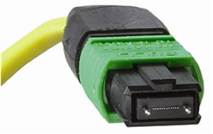
MPO - Multiple Push On. Support for both multi-mode and single-mode fibers. It is aqua colored and can be used only with QSFP form-factors and SR/SR4 transceivers.
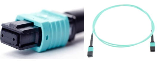
MPO/APC - Multiple Push On with an Angled Polished Connector. Its connector has an angle polish on the fiber to reduce light back reflection into the laser. It is green colored and used for single-mode PSM4/DR4/DR8 and multi-mode SR8 transceivers (not compatible with SR4).
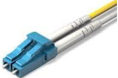
LC - Lucent Connector. A high density fiber connector found on pluggable modules. They usually exist in pairs, one for transmit and one for receive. Can be used with SFP and QSFP form-factors. Aqua colored for multi-mode fibers and yellow colored for single-mode.
Fiber Optics TIA Standard Color Codes
The Telecommunication Industry Association (TIA) is accredited by the American National Standards Institute (ANSI) to develop voluntary, consensus-based industry standards. Many data centers use cables of varying color and don’t adhere to a standard.
| Color | Transceivers Type |
|---|---|
| Single Mode Fiber (OS1 or OS2) | |
| Multi-Mode Fiber (OM1 or OM2) | |
| Multi-Mode Fiber (OM3, OM4) | |
| Multi-Mode Fiber (OM4+) | |
| Multi-Mode Fiber (OM5) | |
| DAC Ethernet Cable |