Custom Topology
The Drag-and-Drop Topology Builder
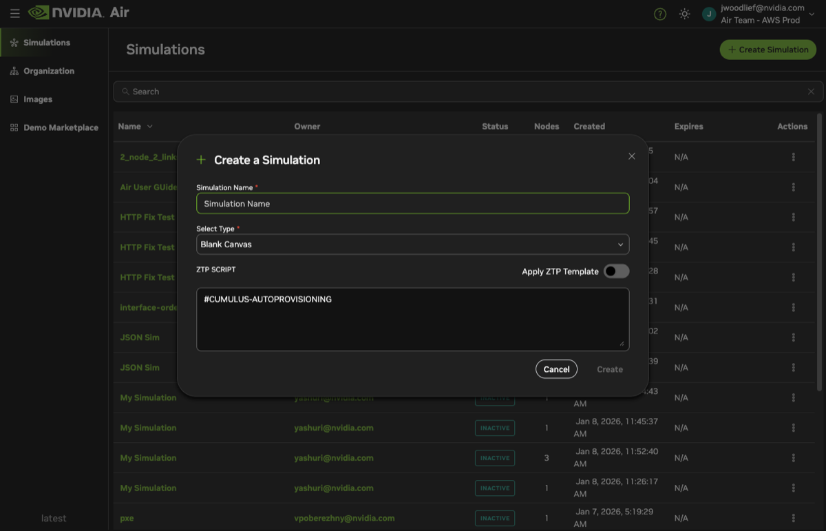
One way to create custom simulations is with the built-in topology builder, which provides a drag-and-drop editor to design any custom network. To get started, navigate to https://dsx-air.nvidia.com/simulations.
- Select Create Simulation.
- Provide a name for your simulation.
- Select Blank Canvas as the type.
- (Optional) Add a ZTP script to the simulation:
- Select Apply ZTP Template.
- Enter your ZTP script. A default script is prefilled to help get you started.
- Click Create.
ZTP Scripts
When you create a new simulation, Air gives you the option to add a zero-touch provisioning (ZTP) script. The ZTP script is copied to the simulation’s oob-mgmt-server. Any node making a ZTP request on the out-of-band management network has access to this ZTP script through a DHCP server and web server running on the oob-mgmt-server.
You must have the out-of-band-network enabled to use ZTP scripts.
A default script is prefilled to help you get started. It implements common ZTP features on Cumulus Linux, such as changing the default password or downloading SSH keys. You can edit the default script directly in the UI.
Manage Nodes
You can drag servers and switches from the System Palette to the workspace. Air provides access to hardware models based on available NVIDIA Spectrum switches. The model does not affect the simulation, but allows Air to pre-populate the number of ports based on the switch model. You do not need to use each port.
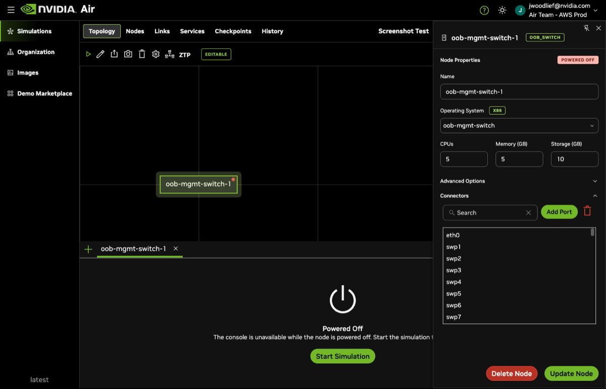
Select a node to view or edit its properties.
- Name: Node hostname.
- Operating System: Name of the OS installed on the node. The OS is installed automatically.
- CPUs: Number of CPUs. The default is 1 or 2 GB depending on the Spectrum switch.
- Memory (GB): Amount of RAM (default is 2 GB).
- Storage (GB): Amount of hard disk space (default is 10 GB).
- Connectors: Choose an available port to connect directly to any port on another node.
Make sure to select Update Node when you complete the changes. You can delete nodes by selecting Delete Node.
Air also provides advanced options, such as enabling UEFI secure boot.
After you create your topology, start the simulation. You cannot add, remove, or edit nodes after the simulation starts for the first time. To edit a simulation that has already been started, revert the simulation to delete its checkpoints and return it to an editable state.
Breakout Ports
For switch nodes, you can break out a port into multiple sub-ports to simulate multi-lane configurations. For example, breaking out swp1 into four sub-ports creates swp1s0, swp1s1, swp1s2, and swp1s3.
To break out a port:
- Select a switch node to open its properties panel.
- In the Connectors section, click Breakout Port.
- Select the ports you want to break out.
- Choose the split type (number of sub-ports) and click Confirm.
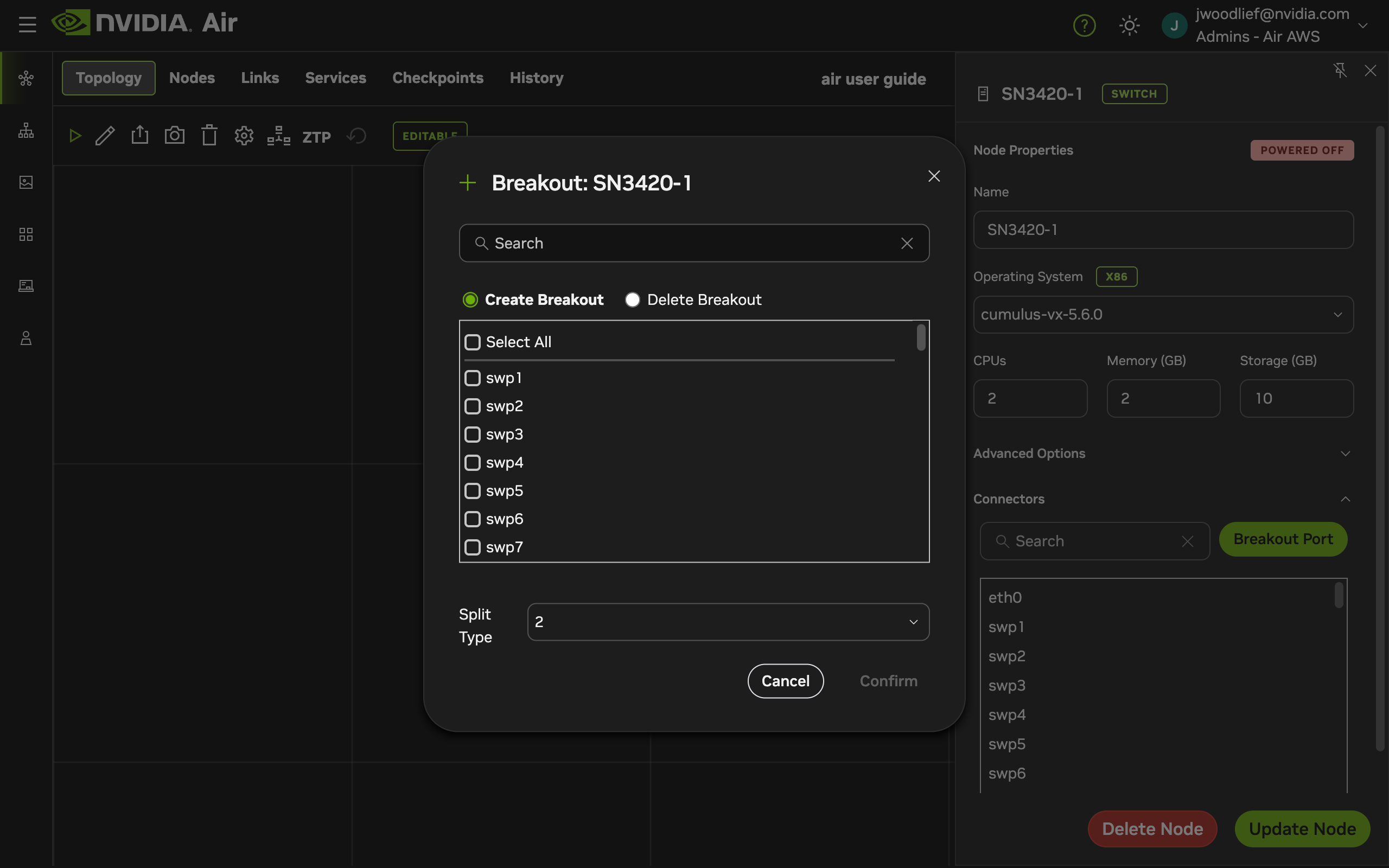
The available split options depend on the switch model. To revert a breakout, select Delete Breakout in the Breakout Port dialog.
Breakout ports can only be configured before the simulation starts for the first time. Only data plane interfaces on switch nodes support breakout — management and OOB interfaces do not.
Outbound Links
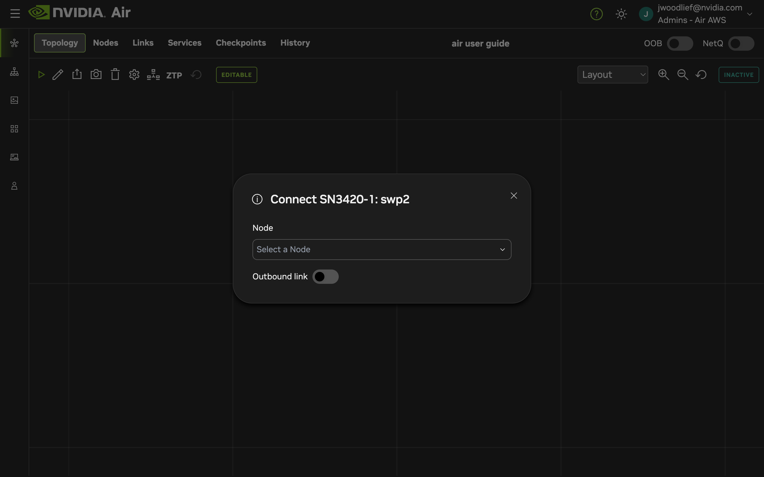
Outbound links connect a node’s interface directly to external networks, giving that interface internet access independently of the OOB management network. This is useful when you need a node to have a public-facing interface — for example, to simulate an edge router or a firewall with an external uplink.
To configure an outbound link:
- Select a node to open its properties panel.
- In the Connectors section, click the port you want to connect externally.
- In the Connect dialog, select Outbound link.
Outbound interfaces appear in the Services tab, where you can create services (such as SSH or HTTP) that terminate on the outbound interface.
An outbound interface connects directly to the external network. It cannot also be connected to another node’s interface.
Troubleshoot Outbound Links
If you do not have service connectivity to an outbound link, try fully initializing the affected interface:
Ensure the interface is up:
ubuntu@my-image:~$ sudo ip link set eth1 upConfigure the interface to receive a DHCP address from the network:
ubuntu@my-image:~$ sudo nano /etc/netplan/40-air.yaml
####################################################### ########
# IMPORTANT: When using NVIDIA Air services,
                                                               #
#  your Internet-facing interface must include the following:  #
#   dhcp6: false                                               #
#   accept-ra: true                                            #
################################################################
network:
  version: 2
  renderer: networkd
  ethernets:
    eth0:
      dhcp4: true
    eth1:            <-------------------
      dhcp4: true    <-------------------
Apply the configuration:
ubuntu@my-image:~$ sudo netplan applyRecreate the service in DSX Air and attempt to connect again.
OOB Management Network
On the System Palette, there is an option to Enable OOB. This setting enables the out-of-band management network that connects all nodes to each other. It also adds an oob-mgmt-switch and oob-mgmt-server to your simulation. When you enable SSH, you connect to the oob-mgmt-server, making this node an ideal starting point for configurations. Air handles the configuration automatically for you.
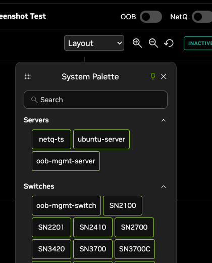
You can add more oob-mgmt-switches and oob-mgmt-servers to your simulation manually even when Enable OOB is set to off. However, you must switch Enable OOB on to use the out-of-band network.
Import Custom Topologies with External Files
You can create custom topologies in Air by importing either JSON (recommended) or DOT files. These files define a network’s nodes, attributes, and connections. You can modify the file with any text editor.
When you upload external topology files directly to Air, you can:
- Share and create copies of a topology
- Save the topology in a reusable file
- Streamline automation
- Generate very large topologies
JSON Files
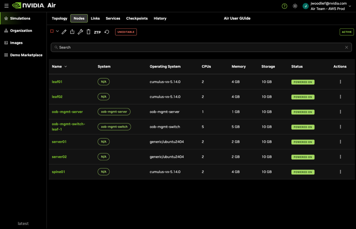
The following JSON topology is an example of a simple topology with 1 spine, 2 leaf nodes, and 2 servers connected to each leaf.
When you view the nodes within Air after starting the simulation, notice that the resources are allocated according to the file:
When you view the links within Air after starting the simulation, notice that the nodes are connected based on the file, and also connected to the out-of-band management network:
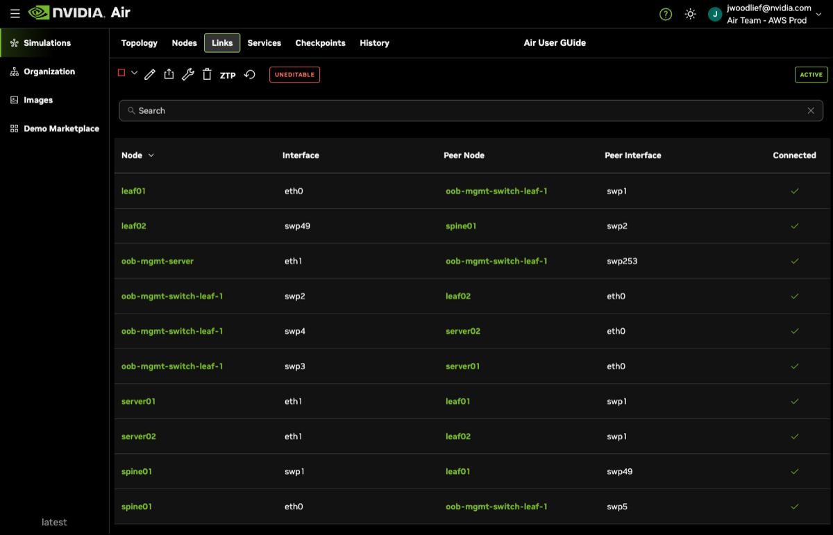
If you omit the oob key in your JSON file, the Enable OOB will still be set to on after you’ve uploaded your file with default resources and will be automatically connected to each node.
Custom OOB Management Network Resources
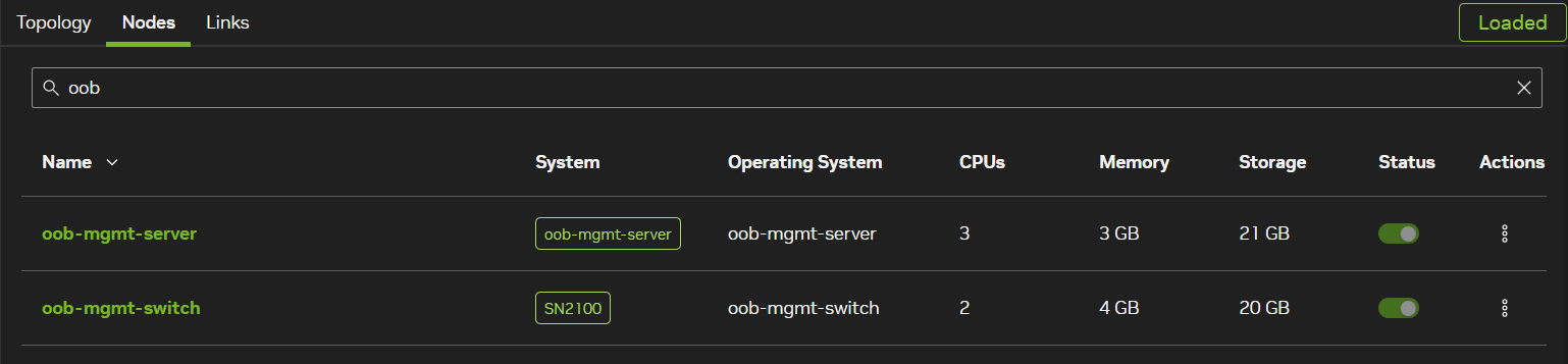
You can specify an oob-mgmt-switch and oob-mgmt-server to customize allocated resources.
When viewing the nodes within Air after starting the simulation, notice that the resources are allocated based on the file:
Boot Order
A node accepts an optional boot attribute that controls which device the node attempts to boot from. It accepts either of two forms:
- Single device (string) — a single boot device, for example
"hd","network", or"cdrom". The default is"hd". - Boot order (list) — a list of up to 3 unique boot devices tried in order. Firmware attempts each device in the order listed and falls through to the next if the previous device does not boot. Accepted device literals are
hd(the boot disk),cdrom(the first user-supplied CD-ROM), andnetwork(every network interface, tried in sequence).
When you supply a list, only the devices you name receive a boot preference; any device not named is left to firmware-level fall-through. The network literal expands to every NIC on the node, each assigned a consecutive boot position. Listing a device that the node does not have (for example network on a node with no NIC) is ignored — the node still boots from the remaining devices.
The boot field is mutually exclusive with pxehost: true. Setting pxehost: true is a legacy alias for boot: "network"; do not set both unless boot is "network".
If boot includes cdrom, the node must also have a cdrom image attached. See CD-ROM.
The following example makes host1 try its disk first, then fall through to network boot:
CD-ROM
A node accepts an optional cdrom attribute that inserts an image into the node’s CD-ROM drive. Set it to the name (or ID) of an image your organization can read. A CD-ROM must be attached whenever the node’s boot order includes cdrom.
DOT Files
You can also create custom topologies in Air using a DOT file, which is the file type used with the open-source graph visualization software, Graphviz. DOT files are simple, customizable, text-based files. DOT files use the .dot file extension.
NVIDIA strongly recommends using JSON over DOT files due to improved validation, scalability, and broader adoption levels.
The following is an example of a simple topology with 1 spine, 2 leaf nodes, and 2 servers connected to each leaf:
graph "Demo" {
  "spine01" [ function="spine" memory="4096" os="cumulus-vx-5.16.1" cpu="2" ]
  "leaf01" [ function="leaf" memory="4096" os="cumulus-vx-5.16.1" cpu="2" nic_model="e1000"]
  "leaf02" [ function="leaf" memory="4096" os="cumulus-vx-5.16.1" cpu="2" secureboot="true"]
  "server01" [ function="server" memory="2048" os="generic/ubuntu2404" cpu="2"]
  "server02" [ function="server" memory="2048" os="generic/ubuntu2204" cpu="3" storage="20"]
    "leaf01":"swp1" -- "server01":"eth1"
    "leaf02":"swp1" -- "server02":"eth1"
    "leaf01":"swp2" -- "spine01":"swp1"
    "spine01":"swp2" -- "leaf02":"swp2"
}
The following sections provide examples for common DOT file customizations.
Operating System
You can set the operating system of the node with the os option:
"server" [os="cumulus-vx-5.16.1"]
Disk Space
By default, nodes in Air have 10 GB of hard disk space. You can increase the space (in GB) by using the storage option:
"server" [os="generic/ubuntu2404" storage="20"]
CPU
You can customize the number of allocated CPUs with the cpu option:
"server" [os="generic/ubuntu2404" cpu="4"]
Boot Order
You can set the boot device(s) with the boot option. Provide a single device (hd, network, or cdrom), or a comma-separated list of up to 3 unique devices for ordered fall-through:
"server" [os="generic/ubuntu2404" boot="network,hd"]
Create Connections
You can create port connections by defining the node and its port with another node and port.
"leaf01":"swp49" -- "leaf02":"swp49"
"leaf01":"swp50" -- "leaf02":"swp50"
Memory
You can customize RAM (in MB) with the memory option:
"server" [os="generic/ubuntu2404" memory="2048"]
Example Topology Files
Labs in the Demo Marketplace are maintained with external GitLab repositories. Here you can find the topology.dot or topology.json file used to build the lab and use it as a reference. To access the files, select Documentation on any lab in the Demo Marketplace. It will direct you to the demo’s GitLab repository, where you can download the file used for the demo topology.
You can also launch a copy of a lab in the Demo Marketplace and then export the JSON file.
Import a Topology
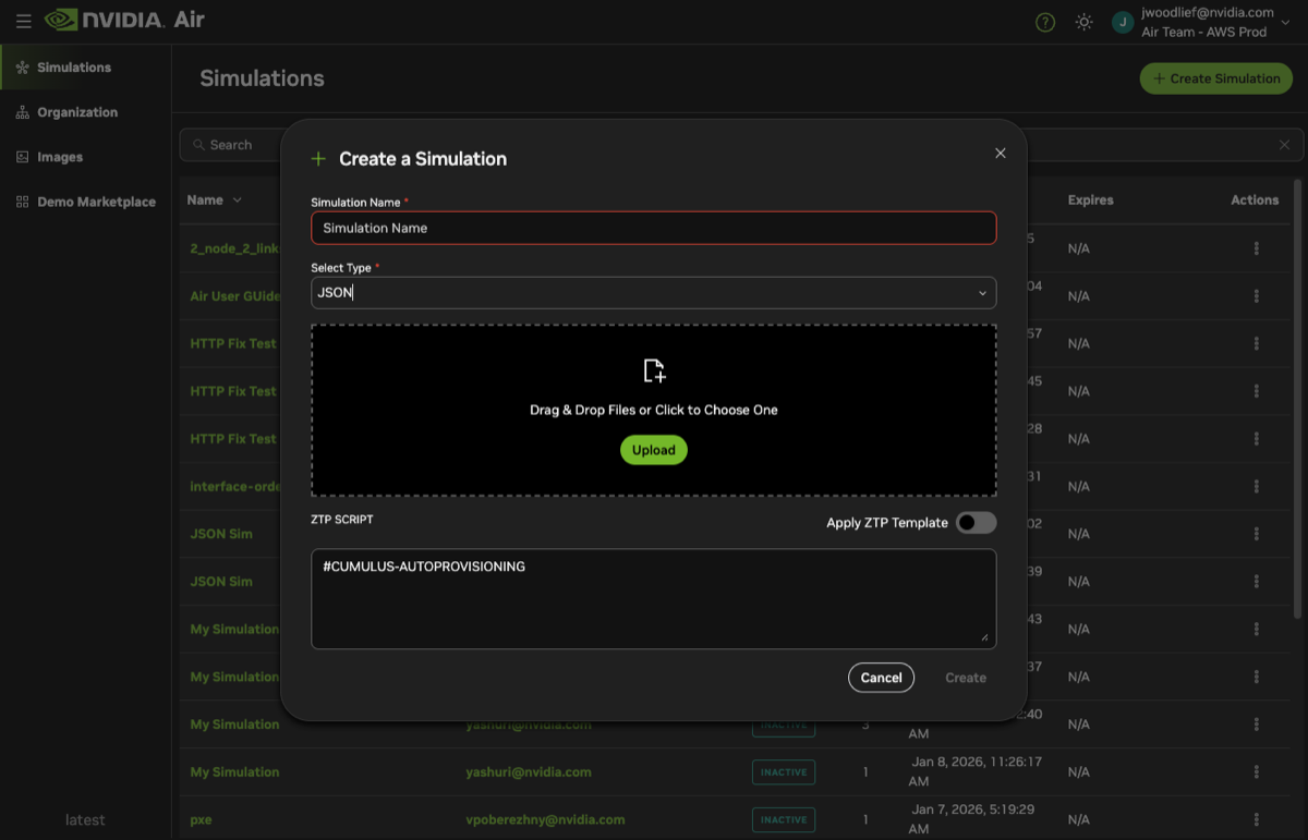
To import and upload a DOT or JSON topology file to Air, navigate to dsx-air.nvidia.com/simulations.
- Click Create Simulation.
- Provide a name for the simulation.
- Select your desired filetype.
- Upload the file to the UI.
- (Optional) Add a ZTP script. Alternately, you can apply a ZTP script within the file.
- Select Apply ZTP Template.
- Enter your ZTP script. A default script is prefilled to help you get started.
- (Optional) Click Advanced and provide an out-of-band management server configuration script that executes on the
oob-mgmt-serverwhen the simulation starts. - Click Create.
Air redirects you to the topology builder, where you can continue to make adjustments.
Import a Topology with the API
You can import JSON formatted topologies through the API.
The following topology defines two nodes (node-1 and node-2) connected to each other through eth1 interfaces. The out-of-band management network is enabled by default.
{
    "nodes": {
        "node-1": {
            "os": "generic/ubuntu2204"
        },
        "node-2": {
            "os": "generic/ubuntu2204"
        }
    },
    "links": [
        [{"node": "node-1", "interface": "eth1"}, {"node": "node-2", "interface": "eth1"}]
    ]
}
The following topology defines two nodes (node-1 and node-2) connected to each other through eth1 interfaces. The out-of-band management network is disabled ("oob": false). The example includes:
- Custom values for configurable node fields (
cpu,memory,storage) - An outbound link (
eth2ofnode-1) that connects directly to external networks. In the links array, use the string"outbound"as the second element instead of a node reference. - A reference to the
osimage by specific UUID (node-2)
{
    "oob": false,
    "nodes": {
        "node-1": {
            "os": "generic/ubuntu2204",
            "cpu": 2,
            "memory": 2048
        },
        "node-2": {
            "os": "defb3ffc-e29b-4d3a-a5fb-41ed1974f938",
            "memory": 2048,
            "storage": 25
        }
    },
    "links": [
        [{"node": "node-1", "interface": "eth1"}, {"node": "node-2", "interface": "eth1"}],
        [{"node": "node-1", "interface": "eth2", "mac": "02:00:00:00:00:07"}, "outbound"]
    ]
}
The string "exit" is also accepted as an alias for "outbound" in the links array.
For additional schemas, refer to the API documentation.
Export a Topology
You can export the topology for any existing simulation as a JSON file. From the Topology tab, click the Export icon in the toolbar to download the topology file.
Export a Topology with the API
You can export existing simulations into a JSON representation using the API. Refer to the API documentation for additional schema details.
Storage Limits
If you increase the storage of a node higher than its default, and Air does not recognize the increased storage, run the following commands on the affected node (not the oob-mgmt-server) to extend the partition and resize the file system:
sudo growpart /dev/vda 1
sudo resize2fs /dev/vda1
Verify the change:
df -h | grep vda1
/dev/vda1        20G  2.1G   18G  11% /