Geometry
The Geometry view takes the state of the Direct3D, OpenGL, or Vulkan machine, along with the parameters for the current draw call, and shows the pre-transformed geometry.
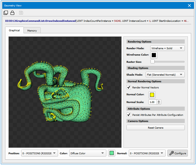
Graphical Tab
Attribute Options
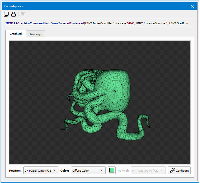
- Position — Specifies the vertex attribute to use for positional geometry data.
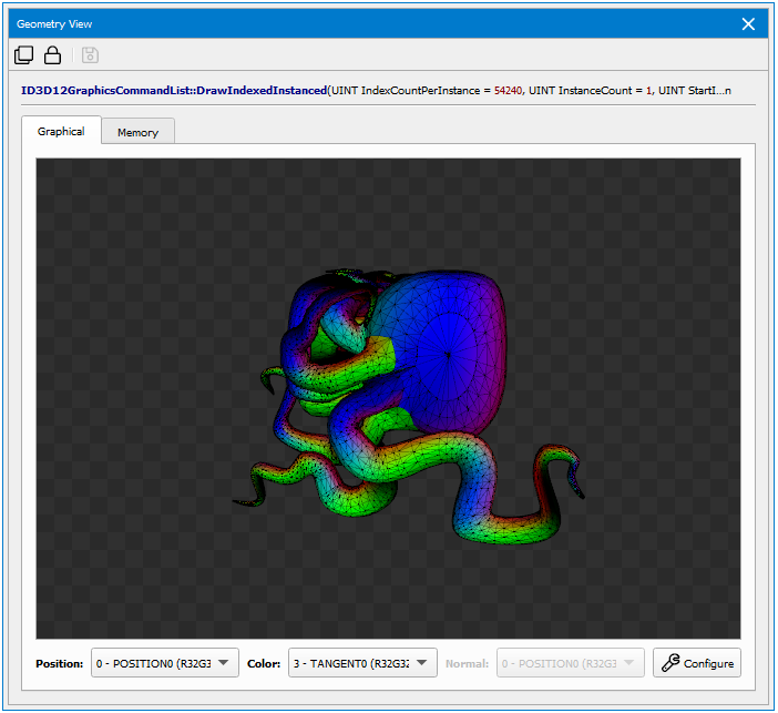
- Color — Specifies how to color the geometry. If Diffuse Color is selected, the selected diffuse color swatch will be used for coloring. If a vertex attribute is selected, the selected attribute will be used for per-vertex coloring.
- Normal — Specifies the per-vertex normal. This selection applies when using a shade mode that specifies Normal Attribute or when rendering normal vectors.
Rendering Options
Clicking Configure in the bottom right corner of the Geometry View will open up the rendering options menu.
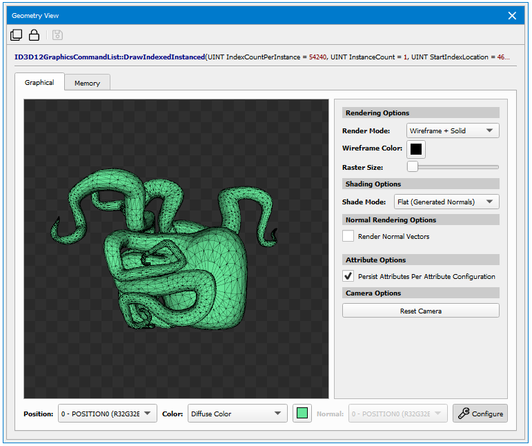
- Reset Camera — Resets the camera to its default orientation. By default, the viewer bounds all geometry with a bounding sphere for optimal orientation.
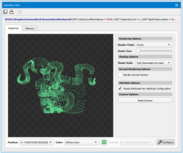
- Render Mode — Determines how to render and raster geometry.
- Solid: renders filled geometry.
- Points: renders a vertex point cloud.
- Wireframe: renders a wireframe of the geometry.
- Wireframe + Solid: renders filled geometry with a wireframe on top of it.
- Shade Mode — Specifies the lighting mode of the rendered image.
- Selected Color Attribute: Shades with the specified color attribute
- Flat Shading Using Generated Normals: Renders the geometry using flat shading with calculated normals
- Flat Sharing Using Normal Attribute: Renders the geometry using flat shading with the specified Normal Attribute.
- Smooth Shading Using Normal Attribute: Renders the geometry using smooth shading with the specified Normal Attribute.
- Render Normal Vectors — Renders the specified normal attribute as a vector pointing from each vertex. The vector may be colored by the Normal Color selection and may be scaled by the Normal Scale selection.
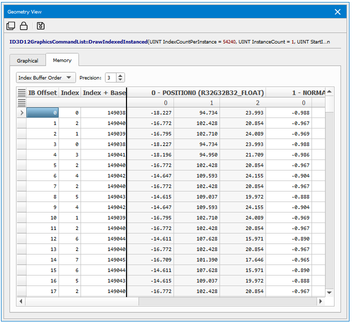
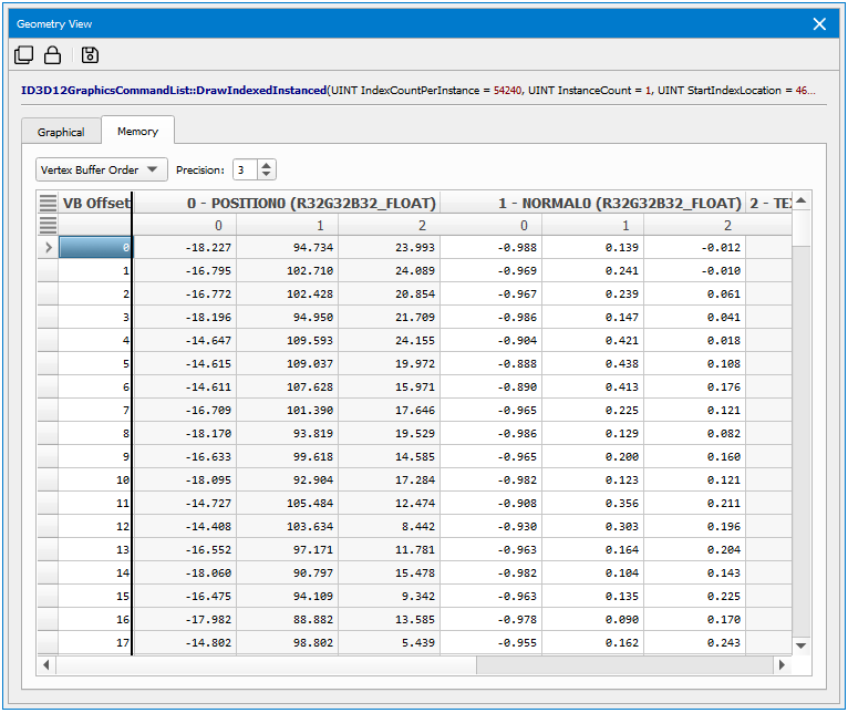
Memory Tab
The Memory tab of the Geometry View shows the contents of the vertex buffer, as interpreted by the current vertex or input attribute specification. There are two modes:
- Index Buffer Order shows the vertices as indexed by the current index buffer and current draw call.
- Vertex Buffer Order shows the vertices as linearly laid out from the start of the vertex buffer and draw call specification.

NVIDIA® Nsight Graphics Documentation Rev. 2018.4.180813 ©2018. NVIDIA Corporation. All Rights Reserved.