Overview
Image Remap applies a generic geometrical transformation to an image. Typical uses include:
- Lens distortion correction.
- User-defined border extension.
- Conversion between different projections.
The algorithm can work on dense or sparse warp maps. A dense warp map stores the remapped position of all pixels in the output image, whereas a sparse map stores a subset of that. It's more efficient to process the latter than the former, but quality might decrease depending on how much distortion is applied by the mapping.
The example below shows the famous "Little Planet" (stereographic) projection applied to a equirectangular panorama image, where \(R\) is the planet radius.
| Input | Mapping | Result |
|---|---|---|
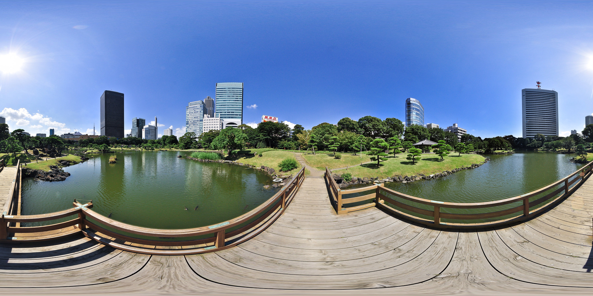 Kyu Shiba Rikyu Garden: on the bridge by heiwa4126 is licensed under CC BY 2.0 | \begin{align*} \theta(x,y) &= \pi + \arctan\left(\frac{y}{x}\right) \\ \phi(x,y) &= \frac{\pi}{2} - 2\arctan\left(\frac{r}{2R}\right) \\ r &= \sqrt{x^2+y^2} \\ \end{align*} | 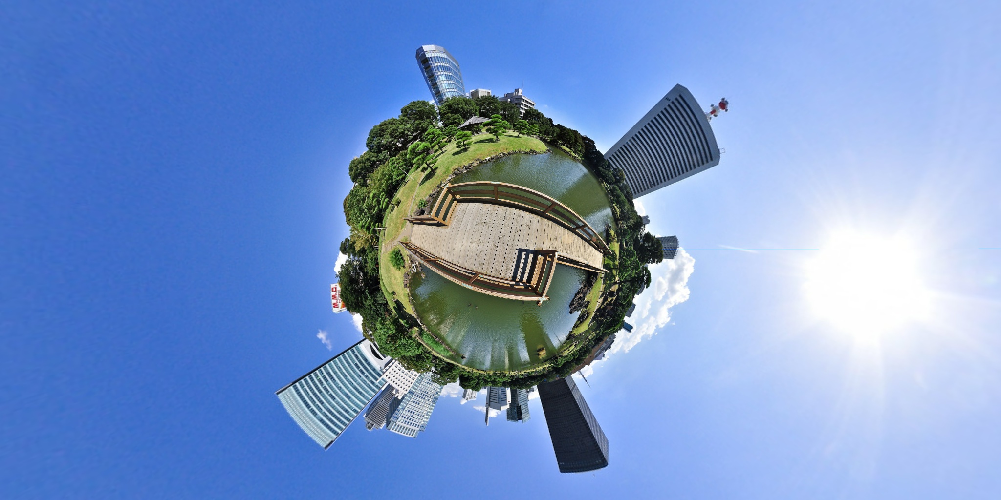 This image is a derivative of Kyu Shiba Rikyu Garden: on the bridge by heiwa4126, used under CC BY 2.0 |
Implementation
The algorithm uses a user-provided VPIWarpMap that maps every pixel in the output image to the corresponding pixel in the input image. It supports dense and sparse mappings.
The mapping operation is composed of two steps:
- A dense map is generated by up-sampling the input sparse map using bi-quadratic interpolation.
- The pixel in the input image corresponding to the control point in the output image is sampled using the user-provided interpolator.
Image Remap supports the following pixel interpolators:
When the corresponding source pixel falls outside image boundary, Image Remap will use the boundary condition to decide what pixel value to pick.
The following boundary conditions are available:
Warp grid definition
Warp grids can be of 3 types:
- dense: provides maximum quality in exchange for some performance hit.
- uniformly sparse: provides a balance between quality and speed. Useful when the distribution of details in the resulting image isn't known a priori.
- non-uniformly sparse: Useful when distribution of details in the resulting image is known. This allows increased quality and performance by sampling less in areas with low detail, and sampling more densely in areas with more detail.
When defining a sparse map, the output image can be split into at most 16 regions (4 horizontally and 4 vertically), with different control point interval (density) in each row or column of regions. The interval spacing must be expressed in power-of-two number of pixels in between control points. There are some other restrictions in the grid layout. Please consult VPIWarpGrid for more information.
To define a dense map, simply set up the warp grid to have just one region, and both horizontal and vertical spacing to 1.
Usage
- Initialization phase
- Include the header that defines the Image Remap functions and Warp Map definition. #include <vpi/WarpMap.h>#include <vpi/algo/ImageRemap.h>
- Define the stream on which the algorithm will be executed and the input image.
- Create the output image. In this particular case both input and output have same dimensions, but this is not required. uint32_t w, h;vpiImageGetSize(input, &w, &h);VPIImageType type;vpiImageGetType(input, &type);VPIImage output;vpiImageCreate(w, h, type, 0, &output);
- Create an dense warp map. VPIWarpMap map;memset(&map, 0, sizeof(map));map.grid.numHorizRegions = 1;map.grid.numVertRegions = 1;map.grid.regionWidth[0] = w;map.grid.regionHeight[0] = h;map.grid.horizInterval[0] = 1;map.grid.vertInterval[0] = 1;vpiWarpMapAllocData(&map);
- Generate a custom mapping suitable to render an equirectangular panorama as a little planet. vpiWarpMapGenerateIdentity will fill the warp map with an identity mapping, i.e., all control points' position will match their position in the output image. Once this is done, the code loops through all control points and using the output coordinate, calculates the corresponding coordinate in the input image. This approach is also taken when performing lens distortion correction for a lens whose distortion model doesn't match the ones provided by VPI. See Lens Distortion Correction for more details. vpiWarpMapGenerateIdentity(&map);{{float x = row[j].x - w / 2.0f;float y = row[j].y - h / 2.0f;const float R = h / 8.0f; // planet radiusconst float r = sqrtf(x * x + y * y);float theta = M_PI + atan2f(y, x);float phi = M_PI / 2 - 2 * atan2f(r, 2 * R);row[j].x = fmod((theta + M_PI) / (2 * M_PI) * (w - 1), w - 1);row[j].y = (phi + M_PI / 2) / M_PI * (h - 1);}}
- Create the algorithm payload with the created mapping. VPIPayload warp;vpiCreateImageRemap(stream, &map, &warp);
- Include the header that defines the Image Remap functions and Warp Map definition.
- Processing phase
- Submit the algorithm to the stream, along with all parameters.
- Optionally, wait until the processing is done. vpiStreamSync(stream);
- Submit the algorithm to the stream, along with all parameters.
For more details, consult the API reference.
Limitations and Constraints
Constraints for specific backends supersede the ones specified for all backends.
PVA
- The following image types are accepted:
- Maximum horizontal and vertical control point interval is 128.
- Maximum input or output dimensions: 16384x16384.
- Only available on Jetson Xavier series.
CUDA
- Not implemented
CPU
- Not implemented
Performance
For further information on how performance was benchmarked, see Performance Measurement.
| size | type | interval | interp. | CPU | CUDA | PVA |
|---|---|---|---|---|---|---|
| 1920x1080 | nv12 | 1 | nearest | n/a | n/a | 2.880 ms |
| 1920x1080 | nv12 | 1 | linear | n/a | n/a | 2.882 ms |
| 1920x1080 | nv12 | 1 | catmull | n/a | n/a | 2.882 ms |
| 1920x1080 | nv12 | 2 | nearest | n/a | n/a | 0.913 ms |
| 1920x1080 | nv12 | 2 | linear | n/a | n/a | 0.912 ms |
| 1920x1080 | nv12 | 2 | catmull | n/a | n/a | 0.914 ms |
| 1920x1080 | nv12 | 4 | nearest | n/a | n/a | 0.669 ms |
| 1920x1080 | nv12 | 4 | linear | n/a | n/a | 0.668 ms |
| 1920x1080 | nv12 | 4 | catmull | n/a | n/a | 0.669 ms |