Overview
VPI provides functions that, together with Remap algorithm, perform image rectification. The input image can have some level of distortion caused by the camera lens. The end result is an undistorted image that can optionally be reprojected into a second camera to allow, for instance, realignment of input camera's optical axis. This makes it an important stage in certain computer stereo vision applications, such as depth estimation, where two cameras must have their optical axis level and parallel.
The following types of distortion models are included:
- Polynomial distortion - encompasses a broad set of common lens distortions, such as barrel, pincushion, a mix of these, etc.
- Fisheye distortion - commonly found in fisheye lenses, can be seen as an exaggerated form of barrel distortion.
For other distortions models, users can always resort to creating their own output-to-input mapping, as shown here.
| Input | Parameters | Output |
|---|---|---|
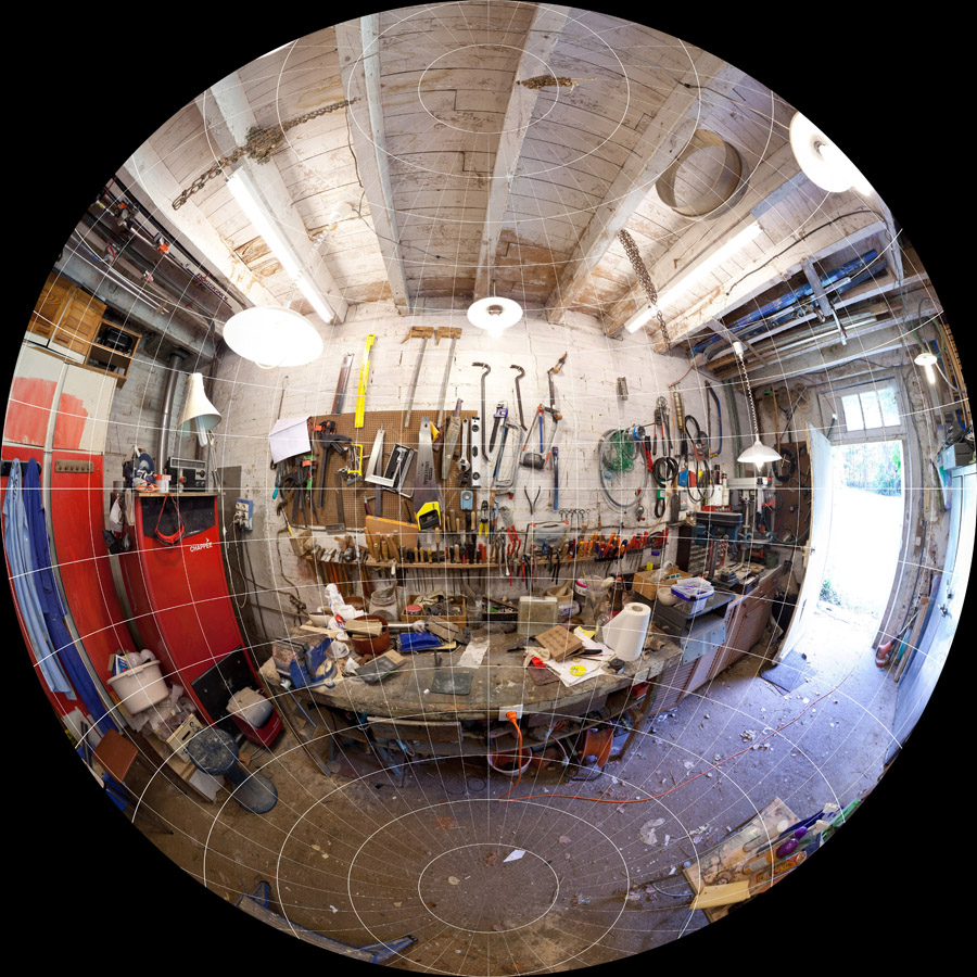 Copyright © 2012 by Michel Thoby, with permission from author. | projection: fisheye equidistant focus length: 7.5mm APS-C k1: -0.126 k2: 0.004 k3: 0 k4: 0 | 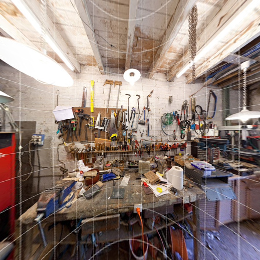 |
Implementation
The Lens Distortion Correction algorithm is implemented by warping the distorted input image into a rectified, undistorted output image. It does so by performing the inverse transformation; i.e., for every pixel \((u,v)\) in the destination image, calculate the corresponding coordinate \((\check{u},\check{v})\) in the input image.
- For each pixel \((u,v)\) in the destination image, calculate its corresponding 3D point \(\mathsf{P_{out}}\), in output camera space using its intrinsics matrix \(\mathsf{K_{out}}\).
\[ \mathsf{P_{out}} = \mathsf{K_{out}}^{-1} \begin{bmatrix} u \\ v \\ 1 \end{bmatrix} \]
- Transform the 3D point \(\mathsf{P_{out}}\) from output camera space to input camera space using the \([\mathsf{R}|\mathsf{t}]^{-1}\) matrix.
\[ \mathsf{P_{in}} = \mathsf{R}^{-1}(\mathsf{P_{out}}-\mathsf{t}) \]
- Apply lens distortion model \(L\) on the ideal (non-distorted) projected point \((\tilde{x},\tilde{y})\), in focal-length units, resulting in distorted point \((x_d,y_d)\). \(s\) is just a scale factor.
\begin{align*} s \begin{bmatrix} \tilde{x} \\ \tilde{y} \\ 1 \end{bmatrix} &= \begin{bmatrix} x \\ y \\ z \end{bmatrix} = \mathsf{P_{in}} \\ (x_d,y_d) &= L(\tilde{x}, \tilde{y}) \end{align*}
- Project distorted point \((\tilde{x},\tilde{y})\) onto the input image space using its intrinsics matrix \(\mathsf{K_{in}}\), resulting in coordinate \((\check{u},\check{v})\). Again, \(s\) is just another scale factor.
\[ s \begin{bmatrix} \check{u} \\ \check{v} \\ 1 \end{bmatrix} = \mathsf{K_{in}} \begin{bmatrix} x_d \\ y_d \\ 1 \end{bmatrix} \]
- Using the user-provided interpolator, sample the input image and assign the result to the corresponding output pixel.
\[ (u,v) \leftarrow S_{\mathsf{interp}}(\check{u},\check{v}) \]
The following interpolators are supported:
The equations above assume a Pinhole Camera Model. In the diagram shown in the link, the input camera is assumed to be aligned with world coordinate frame, with origin at \(O = (0,0,0)\) and optical axis colinear with world's \(Z_w\) axis. The output camera's origin is located at \(F_c\) and optical axis along \(Z_c\). Taken together, this makes the matrix \([R|t]\) transform points from input's camera space into output's.
Lens Distortion Models
These equations above assume that projection is a linear operation. In reality, this is hardly the case. Lens distortions make straight lines in the real world appear projected as bent in the captured image. In order to take this into account, the distortion model is applied to the ideal, distortion-free coordinates in input camera space corresponding to the output image pixel coordinate being rendered. The resulting coordinates are the actual projected position on the input image of the rendered pixel in the output image.
VPI comes with functions that handle both polynomial and fisheye distortion models. These models are characterized by distortion coefficients and, in the case of fisheye lenses, the mapping type. The coefficients are unique for each lens and can either be supplied by the manufacturer or estimated by a lens calibration process.
Polynomial Distortion Model
Polynomial distortion model, also known as Brown-Conrady model, allows representing a broad range of lens distortions, such as barrel, pincushion, mustache, etc.
VPI uses the structure VPIPolynomialLensDistortionModel to store the distortion parameters, which eventually is used by the vpiWarpMapGenerateFromPolynomialLensDistortionModel to create a VPIWarpMap that undistorts the input image.
This distortion model is composed of radial and tangential distortion components:
\begin{align*} L(\tilde{x},\tilde{y}) &= L_r(\tilde{x},\tilde{y}) + L_t(\tilde{x},\tilde{y}) \end{align*}
Radial distortion is defined by parameters \(k_1,k_2,k_3,k_4,k_5\) and \(k_6\):
\begin{align*} L_r(\tilde{x},\tilde{y}) &= \frac{1+k_1r^2+k_2r^4+k_3r^6}{1+k_4r^2+k_5r^4+k_6r^6} \begin{bmatrix} \tilde{x} \\ \tilde{y} \end{bmatrix}\\ r^2 &= \tilde{x}^2 + \tilde{y}^2 \end{align*}
Tangential distortion is defined by parameters \(p_1\) and \(p_2\) and is due to imperfect centering of the lens components and other manufacturing defects.
\begin{align*} L_t(\tilde{x},\tilde{y}) &= \begin{bmatrix} 2p_1\tilde{x}\tilde{y} + p_2(r^2+2\tilde{x}^2) \\ p_1(r^2+2\tilde{y}^2) + 2p_2\tilde{x}\tilde{y} \end{bmatrix} \\ r^2 &= \tilde{x}^2+\tilde{y}^2 \end{align*}
Barrel distortion |
Pincushion distortion |
Mustache distortion |


Fisheye Distortion Model
Fisheye lens is an extremely wide angle lens that produces strong barrel distortion. One of its uses is to create wide panoramas.
VPI uses the structure VPIFisheyeLensDistortionModel to store the distortion parameters, which eventually is used by the vpiWarpMapGenerateFromFisheyeLensDistortionModel to create a VPIWarpMap that undistorts the input image.
The distortion model is defined by a mapping function \(M_f(\theta)\) that depends on fisheye lens type, and coefficients \(k_1,k_2,k_3\) and \(k_4\) as follows:
\begin{align*} L(\tilde{x},\tilde{y}) &= \frac{r_d}{r} \begin{bmatrix} \tilde{x} \\ \tilde{y} \end{bmatrix} \\ r_d &= M_1(\theta_d) \\ \theta_d &= \theta(1+ k_1\theta^2 + k_2\theta^4 + k_3\theta^6 + k_4\theta^8) \\ \theta &= \arctan(r) \\ r &= \sqrt{\tilde{x}^2 + \tilde{y}^2} \end{align*}
where:
- \(\theta\) is the incident light angle with respect to camera's optical axis.
- \(\theta_d\) is the distorted incident light angle, usually due to lens manufacturing defects.
- \(r_d\) is the distance from principal point where the incident light is recorded on the image.
Fisheye lenses can be classified depending on the relationship between the angle of incident light and where it is recorded on the image, established by the mapping function \(M_f(\theta)\).
- Note
- In these formulas \(f=1\) as this is the focal length related to the projected \((\tilde{x},\tilde{y})\) coordinates.
VPI supports the following mapping functions, each one with some desirable characteristics:
- VPI_FISHEYE_EQUIDISTANT : maintains angular distances.
\[M_f(\theta) = f\theta\]
- VPI_FISHEYE_EQUISOLID : maintains surface relations; i.e., every pixel subtends an equal solid angle, or an equal area on the unit sphere.
\[M_f(\theta) = 2f\sin\left(\frac{\theta}{2}\right)\]
- VPI_FISHEYE_ORTHOGRAPHIC : maintains planar illuminance.
\[M_f(\theta) = f\sin(\theta)\]
- VPI_FISHEYE_STEREOGRAPHIC : maintains angles.
\[M_f(\theta) = 2f\tan\left(\frac{\theta}{2}\right)\]
Usage
- Initialization phase
- Include the header that defines the lens distortion models and Remap algorithm. #include <vpi/LensDistortionModels.h>#include <vpi/algo/Remap.h>
- Define the input image object. VPIImage input = /*...*/;
- Create the output image, which in this case has the same dimensions and format as input. uint32_t width, height;vpiImageGetSize(input, &width, &height);VPIImageFormat type;vpiImageGetType(input, &type);VPIImage output;vpiImageCreate(width, height, type, 0, &output);
- Create a dense warp map for warping the distorted image into the corrected output. VPIWarpMap map;memset(&map, 0, sizeof(map));map.grid.numHorizRegions = 1;map.grid.numVertRegions = 1;map.grid.regionWidth[0] = width;map.grid.regionHeight[0] = height;map.grid.horizInterval[0] = 1;map.grid.vertInterval[0] = 1;vpiWarpMapAllocData(&map);
- Define the fisheye lens distortion model with mapping type and distortion coefficients. The latter comes from a lens calibration process. VPIFisheyeLensDistortionModel fisheye;memset(&fisheye, 0, sizeof(fisheye));fisheye.mapping = VPI_FISHEYE_EQUIDISTANT;fisheye.k1 = -0.126;fisheye.k2 = 0.004;fisheye.k3 = 0;fisheye.k4 = 0;
- Define the intrinsic and extrinsic camera parameters. The input image was recorded by an APS-C sensor and the lens has focal length of 7.5mm. The principal point is right on image center. Finally, since this is a monocular setup, extrinsic parameters are identity, meaning that input and output cameras are in the same position with optical axis aligned. float sensorWidth = 22.2; // APS-C sensorfloat focalLength = 7.5;float f = focalLength*width/sensorWidth;{{ f, 0, width/2.0 },{ 0, f, height/2.0 }};{{ 1, 0, 0, 0 },{ 0, 1, 0, 0 },{ 0, 0, 1, 0 }};
- Bake into the warp map correction implied by the lens distortion model defined above. vpiWarpMapGenerateFromFisheyeLensDistortionModel(K, X, K, &fisheye, &map);
- Create a payload for the remap algorithm that will perform the correction. The payload is created on the CUDA backend, that eventually will execute the algorithm. VPIPayload warp;vpiCreateRemap(VPI_BACKEND_CUDA, &map, &warp);
- Create the stream where the algorithm will be submitted for execution. VPIStream stream;vpiStreamCreate(0, &stream);
- Include the header that defines the lens distortion models and Remap algorithm.
- Processing phase
- Submit the algorithm to the stream, along with all parameters. We're using a cubic interpolator for maximum quality, and mapped pixels that fall outside source image boundaries are considered black.
- Optionally, wait until the processing is done. vpiStreamSync(stream);
- Submit the algorithm to the stream, along with all parameters. We're using a cubic interpolator for maximum quality, and mapped pixels that fall outside source image boundaries are considered black.
- Cleanup phase
- Free resources held by the stream, the payload, the warp map and the input and output images. vpiStreamDestroy(stream);vpiPayloadDestroy(warp);vpiWarpMapFreeData(&map);vpiImageDestroy(input);vpiImageDestroy(output);
- Free resources held by the stream, the payload, the warp map and the input and output images.
For a complete example, consult the sample application Fisheye Distortion Correction. It implements the whole process of rectifying images captured by a fisheye lens, including the calibration process.
For more details, consult the Lens Distortion Correction API reference.
Limitations and Constraints
Since processing is ultimately done by Remap algorithm, lens distortion correction inherits its limitations and constraints.
Performance
The main loop of Lens Distortion Correction uses Remap, therefore performance is dominated by it. Refer to Remap's performance tables.