Overview
Perspective Warp algorithm allows for correcting perspective distortion caused by camera misalignment with respect to the object plane being captured. This is the case when the camera is, for instance, pointing to a frame hanging on a wall, but looking from below. The resulting image won't have opposite sides that are parallel.
If the camera position, tilt and pan relative to the frame are known, a 3x3 pespective transform can be derived, which will warp the image in order to keep frame's opposite sides parallel to each other, as shown below.
| Input | Transform | Corrected |
|---|---|---|
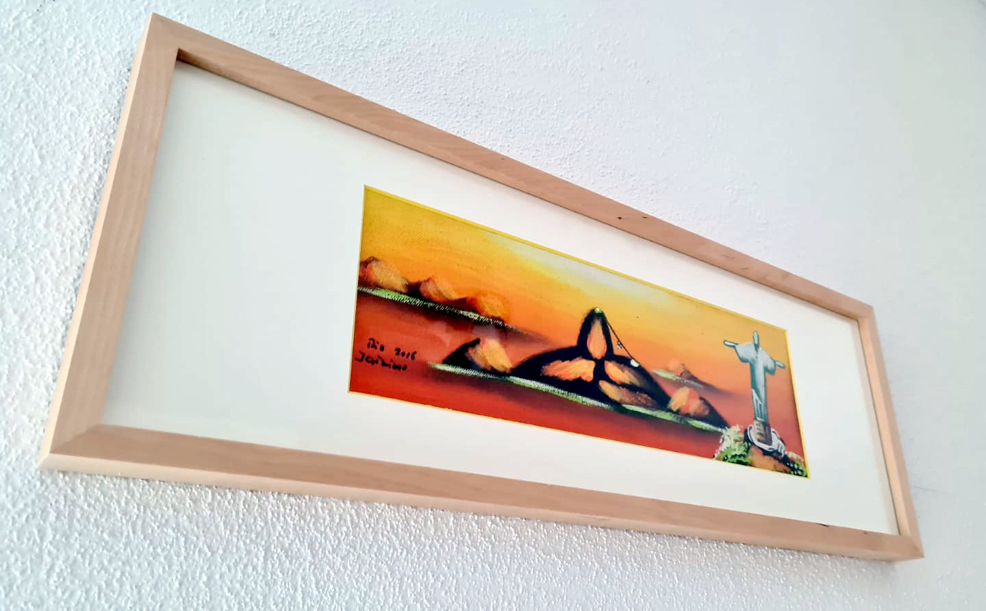 | \begin{bmatrix} 0.5386 & 0.1419 & -74\\ -0.4399 & 0.8662 & 291.5\\ -0.0005 & 0.0003 & 1 \end{bmatrix} | 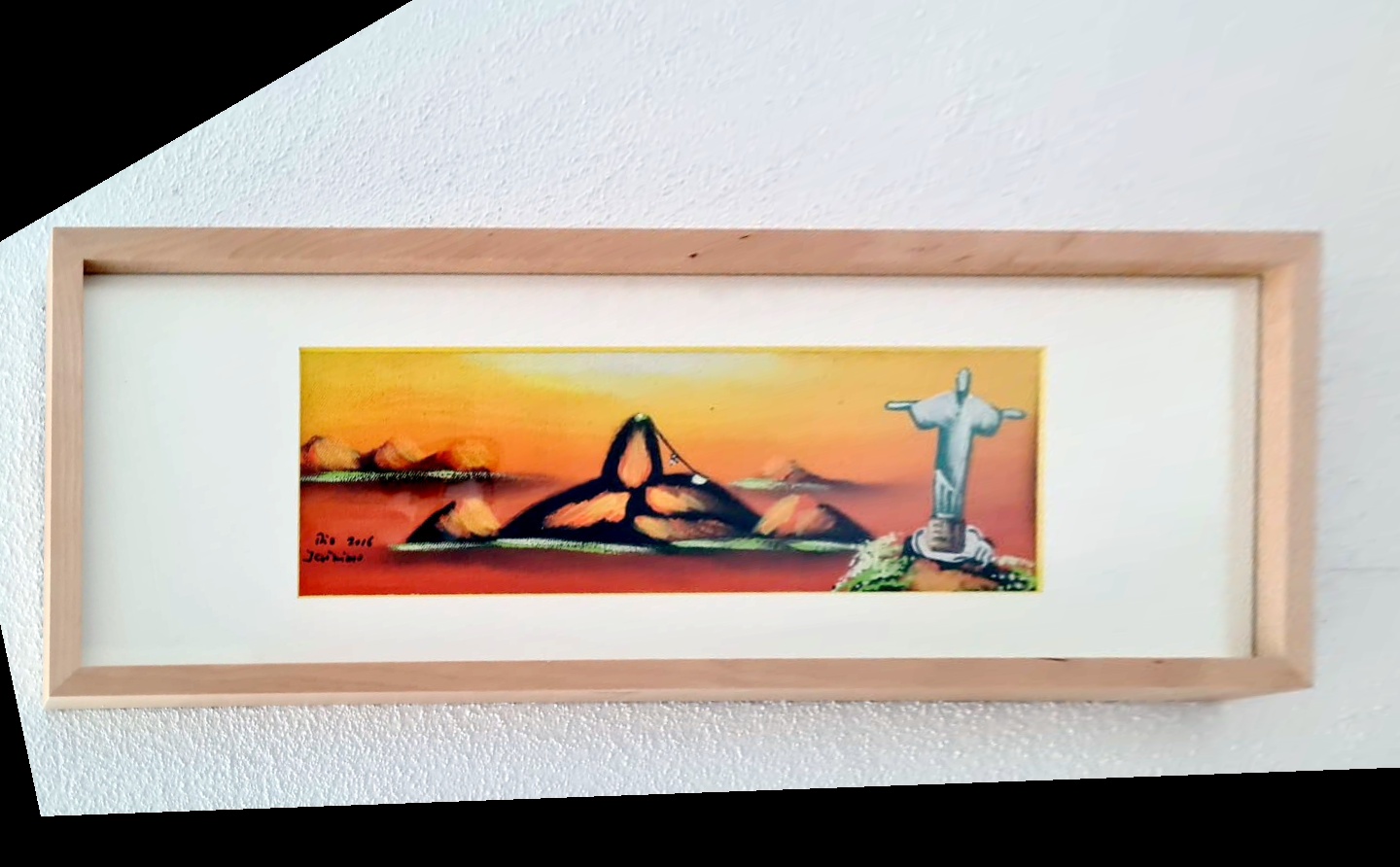 |
Implementation
The perspective transform matrix maps the source image into the destination image. The transform can be described mathematically by the equation below:
\begin{align*} \mathsf{y} = \mathsf{H}_p \mathsf{x} = \begin{bmatrix} \mathsf{A} & \mathsf{t} \\ \mathsf{p}^\intercal & p \end{bmatrix} \mathsf{x} \end{align*}
or, expanding the matrices and vectors:
\begin{align*} \begin{bmatrix} y_u \\ y_v \\ y_w \end{bmatrix} &= \begin{bmatrix} a_{11} & a_{12} & t_u \\ a_{21} & a_{22} & t_v \\ p_0 & p_1 & p \end{bmatrix} \begin{bmatrix}x_u \\ x_v \\ 1 \end{bmatrix} \\ \end{align*}
In these equations,
- \(\mathsf{H}_p\) is the projection matrix
- \(\mathsf{x}\) is the homogeneous coordinates in the source image.
- \(\mathsf{y}\) is the homogeneous coordinates in the destination image.
- \(\mathsf{A}\) is a 2x2 non-singular matrix with the linear component.
- \(\mathsf{t}\) is the translation component.
- \(\mathsf{p},p\) are the projective components. \(p\) is usually 1.
The projection of \(\mathsf{y}\) onto the output image is then given by:
\begin{align*} \begin{bmatrix} y'_u \\ y'_v \end{bmatrix} &= \begin{bmatrix} y_u/y_w \\ y_v/y_w \end{bmatrix} \end{align*}
These equations are efficiently implemented by doing the reverse operation, i.e, applying the inverse transform on destination pixels and sample the corresponding values from source image. If flag VPI_WARP_INVERSE is passed, the operation will assume that user's matrix is already inverted and won't try to invert it again. Pass zero if matrix must be inverted by VPI.
\begin{align*} \mathsf{H}_p^{-1} &= \begin{bmatrix}h_{11} & h_{12} & h_{13} \\ h_{21} & h_{22} & h_{23} \\ h_{31} & h_{32} & h_{33}\end{bmatrix} \\ \mathrm{dst}(u,v) &= \mathrm{src}\left(\frac{h_{11}u+h_{12}v+h_{13}}{h_{31}u+h_{32}v+h_{33}},\frac{h_{21}u+h_{22}v+h_{23}}{h_{31}u+h_{32}v+h_{33}}\right), \forall (u,v) \in \mathrm{dst} \end{align*}
The source and destination images may have different dimensions. They must have the same type, though.
Interpolation is used when the source coordinate doesn't fall exactly on a pixel. Perspective Warp accepts the following interpolation modes:
The only boundary mode currently supported is:
- VPI_BOUNDARY_COND_ZERO - Sampling outside source image boundary will return a black value. This can be seen in the corrected image on top of this page, the black regions fall outside source image.
Usage
- Initialization phase
- Include the header that defines the Perspective Warp function. #include <vpi/algo/PerspectiveWarp.h>
- Define the input image object. VPIImage input = /*...*/;
- Create the output image. In this particular case both input and output have same dimensions, but they could be different. The image formats must match, though. uint32_t w, h;vpiImageGetSize(input, &w, &h);VPIImageFormat type;vpiImageGetType(input, &type);VPIImage output;vpiImageCreate(w, h, type, 0, &output);
- Create the algorithm payload in the CPU backend. VPIPayload warp;vpiCreatePerspectiveWarp(VPI_BACKEND_CPU, &warp);
- Create the stream where the algorithm will be submitted for execution. VPIStream stream;vpiStreamCreate(0, &stream);
- Include the header that defines the Perspective Warp function.
- Processing phase
- Define the perspective transform to be applied. Note that the transform doesn't have to be the same in every call. VPIPerspectiveTransform xform ={{ 0.5386, 0.1419, -74 },{-0.4399, 0.8662, 291.5},{-0.0005, 0.0003, 1 }};
- Submit the algorithm to the stream, along with all parameters. The algorithm will be executed by the backend where the payload was created, CUDA. vpiSubmitPerspectiveWarp(stream, warp, input, xform, output, VPI_INTERP_LINEAR, VPI_BOUNDARY_COND_ZERO, 0);
- Optionally, wait until the processing is done. vpiStreamSync(stream);
- Define the perspective transform to be applied. Note that the transform doesn't have to be the same in every call.
- Cleanup phase
- Free resources held by the stream, the payload, and the input and output images.
For more details, consult the Perspective Warp API reference.
Limitations and Constraints
Constraints for specific backends supersede the ones specified for all backends.
All backends
- Supported image formats
- Supported boundary conditions
CUDA and CPU
- Do not support VPI_IMAGE_FORMAT_NV12_BL
VIC
- Only available on Jetson Xavier devices.
- The following image formats are supported:
PVA
- Not implemented.
Performance
For information on how to use the performance table below, see Algorithm Performance Tables.
Before comparing measurements, consult Comparing Algorithm Elapsed Times.
For further information on how performance was benchmarked, see Performance Measurement.