Networking Physical Topologies#
H200 NVL System Networking#
The NVIDIA platform networking configuration enables the highest Al performance and scale, while ensuring enterprise manageability and security. It leverages the NVIDIA expertise in Al data centers and optimizes network traffic flow:
East-West (Compute Network) traffic: This refers to traffic between NVIDIA H200 NVL systems within the cluster, typically for multi-node Al training, HPC collective operations, and other workloads. These recommendations are critical for AI processing, handling internal data transfers that affect model training and scaling, requiring high bandwidth and low latency solutions. These are tailored for AI clusters to improve communication between GPUs and other components, ensuring seamless data flow within the data center. This is critical for scaling as data is processed and passed between various layers in AI models (across GPUs, CPUs, and storage). Poorly managed east-west traffic can lead to bottlenecks, slowing down training times and reducing the overall efficiency of the AI pipeline.
North-South (Customer and Storage Network) traffic: This involves traffic between NVIDIA H200 NVL systems and any external resources including cloud management and orchestration systems, remote data storage nodes, and other parts of the data center or the Internet. Supports external communication and is especially important for storage connectivity for data ingestion and result delivery. Presently, NVIDIA recommends NVIDIA BlueField Data Processing Units (DPUs) for all North-South traffic to offload and ensure secure, efficient handling of requests from outside the network.
Switching: For all Enterprise RAs, NVIDIA provides configuration recommendations for Ethernet, which is the preferred switching for enterprise workloads.
For optimal performance, it is recommended to use NVIDIA networking in conjunction with the NVIDIA H200 NVL platform. NVIDIA networking platforms provide end-to-end InfiniBand and Ethernet connectivity solutions. Combined with NVIDIA Spectrum-X Ethernet, NVIDIA H200 NVL platform delivers the highest performance for DL training and inference, data science, scientific simulation, and other modern workloads.
Network Topology Diagram#
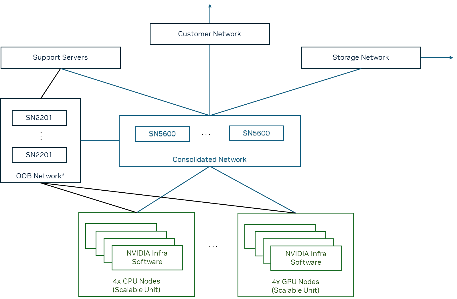
Note
Optional: NVIDIA Base Command Manager Essentials can use the OBB Network to deploy and manage compute nodes.
The configuration is built upon building blocks of scalable units (SU), each containing 4 partner servers, which provides for rapid deployment of systems of multiple sizes and networked via the OOB and Consolidated Network. The software stack will remain consistent regardless of the chosen networking configuration. Additional detailed physical networking references are available for partners who want to build high-performance, scalable data center solutions.