

Understanding Your Vera-Rubin NVL72 System#
Before tuning applications, confirm which rack, tray, GPU, NIC, and CPU topology the job is actually running on. Vera-Rubin NVL72 keeps the familiar rack-scale NVL72 programming target, but the components and ratios differ from earlier NVL72 systems.
Rack Topology#
The rack is organized around 18 compute trays and 9 NVLink 6 switch trays. Each compute tray is one host OS image with two Vera CPUs, four Rubin GPUs, eight ConnectX-9 east-west NIC ASICs, and one BlueField-4 north-south DPU. Four serviceable passive cable cartridges provide the rack-side NVLink backplane.
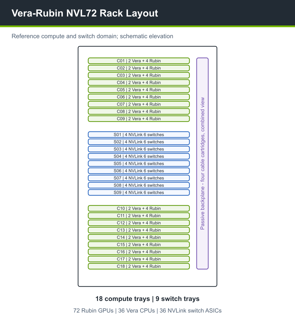
Figure 2 Vera-Rubin NVL72 rack layout.#
Use the rack inventory and topology tools before running performance tests:
hostname
lscpu
numactl -H
nvidia-smi -L
nvidia-smi topo -m
lspci -tv
ibdev2netdev
ucx_info -d
Keep command output with benchmark results. It is difficult to diagnose collective, NIC-sharing, or CPU locality issues after the fact if the topology snapshot is missing.
Compute Tray Topology#
Each compute tray has two HPMs. Each HPM contains one Vera CPU and two Rubin GPUs. The tray uses SOCAMM LPDDR5X memory, NVLink-C2C between Vera and Rubin, PCIe Gen6 I/O, and one operating system instance for all four GPUs.
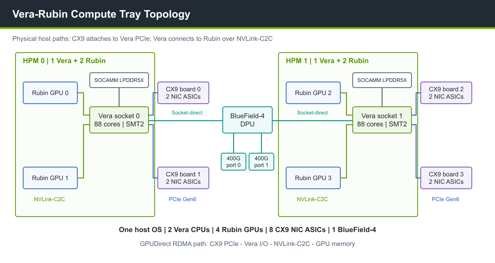
Figure 3 Compute tray organization with two HPMs, CPU-attached CX9 boards, and a socket-direct BlueField-4 DPU. GPUDirect RDMA accesses GPU buffers through the CPU PCIe and NVLink-C2C paths; a GPU/NIC association is not a direct wire.#
Important tray-level resources:
2 Vera CPU sockets.
4 Rubin GPU packages.
4 network boards carrying 8 ConnectX-9 NIC ASICs.
1 BlueField-4 DPU with dual 400 Gb/s QSFP112 ports for north-south connectivity.
4 Gen6 E1.S data SSDs associated with the I/O complex.
1 Gen5 E1.S boot SSD.
1 1GbE utility NIC for deployment, debug, and manufacturing flows.
Baseboard, HMC, BMC, and tray management controllers.
The expected CPU shape for a full tray is 88 cores per Vera socket and
352 logical CPUs with Spatial Multithreading (SMT2) enabled. With one thread
enabled per core, the tray exposes 176 logical CPUs. Check the active SMT mode
and installed SOCAMM LPDDR5X capacity before sizing rank CPU masks or memory
allocations. For one rank per GPU, start with one CPU
host-memory NUMA domain per two GPU packages or an explicit per-rank CPU mask
derived from lscpu, numactl -H, and nvidia-smi topo -m. Vera-Rubin
systems can expose additional GPU or MIG NUMA nodes, so do not treat every NUMA
node in lscpu as CPU-local memory. Do not reuse older core counts or socket
masks.
Vera CPU Settings#
Use the release-qualified OS image, kernel, and firmware for the deployed system. The Vera platform patches and configurations document tracks enablement and fixes; a kernel version alone does not show whether a vendor image includes the required backports. The following settings are the most relevant when tuning GPU scale-out workloads:
Use a 64 KB host kernel when the software stack supports it and confidential computing requirements do not force 4 KB pages.
Disable Linux AutoNUMA for Vera-Rubin GPU workloads unless a specific workload has been validated with it enabled.
Use Coherent Driver-Based Memory Management (CDMM) as the baseline for GPU workloads. Starting with R615, CDMM is the driver default on hardware-coherent platforms:
NVreg_CoherentGPUMemoryMode=driverkeeps GPU memory under driver management instead of onlining it as Linux NUMA memory. Some unified-memory HPC applications benefit from NUMA mode; follow the application and platform guidance and measure that mode separately. See the HPC SDK release notes.Consider
iommu.passthrough=1on bare metal only when platform guidance requires it and deployment security policy permits it. Verify the effective IOMMU mode after changes.Retain the platform-qualified PCIe ACS and isolation configuration. Diagnose redirected peer traffic from the discovered topology; blanket ACS changes are not a portable tuning recipe.
Record Vera PCIe routing when debugging I/O. The HPM has 96 Gen6-capable lanes per Vera socket, but the tray midplane assigns those lanes to CX9, BlueField-4, CPU-to-CPU coherent links, GPU links, boot SSD, and management paths.
Build CPU-heavy code with Vera-aware compiler support, such as GCC 15.2 or newer with
-mcpu=olympusor LLVM 21 or newer when available. Confirm that the installed compiler recognizes the target. NVIDIA HPC SDK 26.9 adds-tp=veraand-tp=olympus. Keep the compiler, optimization flags, and floating-point settings with the run record.Measure CPU cache behavior separately from GPU communication. Vera’s L2 and Scalable Coherency Fabric behavior can change preprocessing, launch, and host-assisted data movement bottlenecks.
Record CPU power limits when comparing runs. Vera CPU power is configurable and can change the available tray-level power budget.
Example checks:
# Confirm socket, core, and thread topology.
lscpu | grep -E 'Socket|Core|Thread|NUMA|Model name'
cat /sys/devices/system/cpu/smt/active

# Confirm AutoNUMA state.
cat /proc/sys/kernel/numa_balancing

# Confirm kernel page size.
getconf PAGE_SIZE

# Check the active NVIDIA coherent GPU memory mode, not only config files.
grep Coherent /proc/driver/nvidia/params
NVLink 6 Domain#
Vera-Rubin NVL72 exposes a rack-scale 72-GPU NVLink 6 L1 domain through 36 NVLink switch ASICs. Four passive cable cartridges provide the rack backplane connectivity. Treat a full rack as one NVLink 6 domain for application placement and collective tuning.
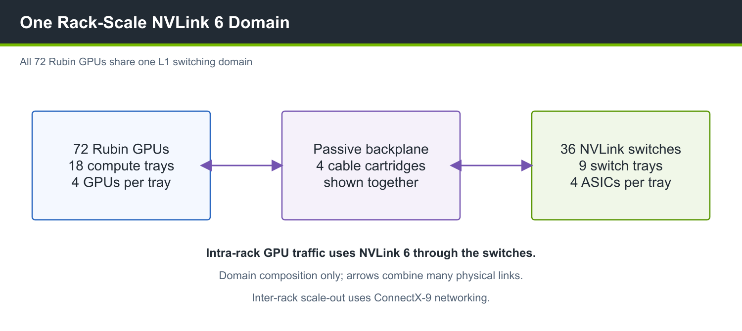
Figure 4 Rack-scale 72-GPU NVLink 6 domain.#
When validating a rack:
Confirm four physical GPU packages per compute tray and 72 across the full rack inventory. A local host’s inventory covers its own tray; MIG and other partitioned modes can change the CUDA device count presented to a job.
Confirm NVLink links and switch devices are healthy before running network benchmarks.
Dump NCCL topology on first use after a software or firmware update.
Compare single-tray, partial-rack, and full-rack collectives separately.
Networking Planes#
Vera-Rubin NVL72 separates GPU scale-out, north-south data center connectivity, NVLink management, and out-of-band management into different planes.
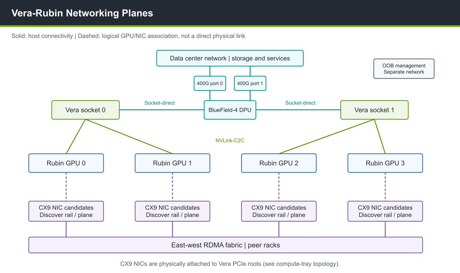
Figure 5 High-level networking planes in one compute tray.#
East-west traffic is carried by ConnectX-9 NICs. The reference design has two CX9 NIC ASICs per Rubin GPU package, or eight CX9 NIC ASICs per compute tray. North-south connectivity uses BlueField-4 with dual 400 Gb/s ports for 800 Gb/s per tray. NIC numbering and rail/plane assignment depend on the deployed fabric; derive them from discovery and the release-qualified network configuration.
Do not carry forward previous-generation NIC, DPU, or NVLink assumptions from older guides.