Initial Cluster Setup#
The deployment stage of a DGX SuperPOD consists of using BCM to provision and manage the Slurm cluster.
Configure the NFS server.
User home directories (home/) and shared data (cm_shared/) directories must be shared between head nodes (such as the DGX OS image) and must be stored on an NFS filesystem for HA availability. Because DGX SuperPOD does not mandate the nature of the NFS storage, the configuration is outside the scope of this document. This DGX SuperPOD deployment uses the NFS export path provided in the site survey /var/nfs/general. The following parameters are recommended for the NFS server export file /etc/exports.
/var/nfs/general *(rw,sync,no_root_squash,no_subtree_check)
Configure the DGX systems to PXE boot by default.
Using either KVM or a crash cart, connect to the DGX system, enter the BIOS menu, and configure Boot Option #1 to be [NETWORK].
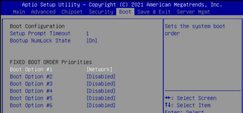
Ensure that other Boot Options are [Disabled] and go to the next screen.
Set Boot Option #1 and Boot Option #2 to use IPv4 for Storage 4-2 and Storage 5 2.
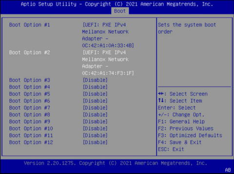
Ensure that other Boot Options are [Disabled].
Select Save & Exit.
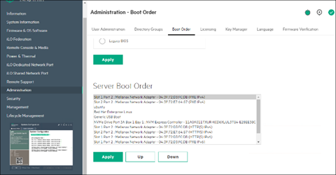
- On the failover head node and the CPU nodes, ensure that Network boot is configured as the primary option. Ensure that the Mellanox ports connected on the network on the head and CPU nodes are set to Ethernet mode as well.
This is an example of a system that will boot from the network with Slot 1 Port 2 and Slot 2 Port 2.
Download the BCM installer ISO.
Burn the ISO to a DVD or to a bootable USB device.
It can also be mounted as virtual media and installed using the BMC. The specific mechanism for the latter will vary by vendor.
Ensure that the BIOS of the target head node is configured in UEFI mode and that its boot order is configured to boot the media containing the BCM installer image.
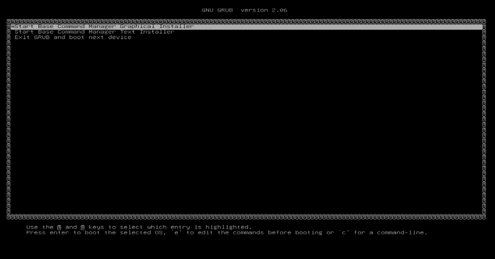
Boot the installation media.
At the grub menu, choose Start Base Command Manager Graphical Installer.
Select Start installation on the splash screen.
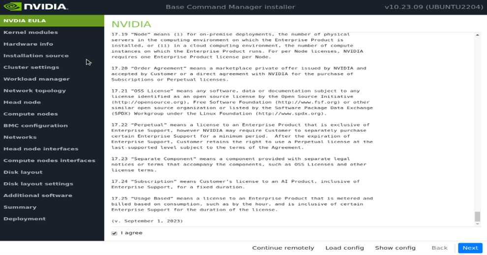
Accept the terms of the NVIDIA EULA by checking I agree and then select Next.
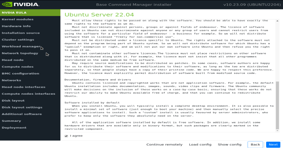
Accept the terms of the Ubuntu Server UELA by checking I agree and then select Next.
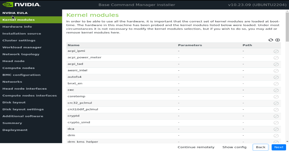
Unless instructed otherwise, select Next without modifying the kernel modules to be loaded at boot time.
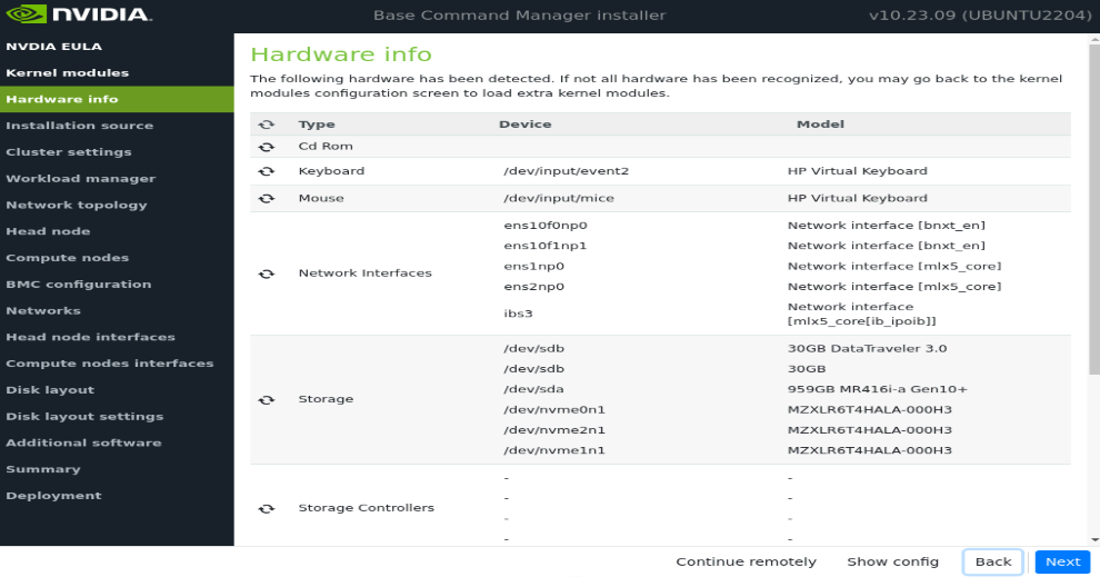
Verify the Hardware info is correct and then select Next.
For example, that the target storage device and the cabled host network interfaces are present (in this case three NVMe drives are the target storage device, and ens1np0 and ens2np01 are the cabled host network interfaces).
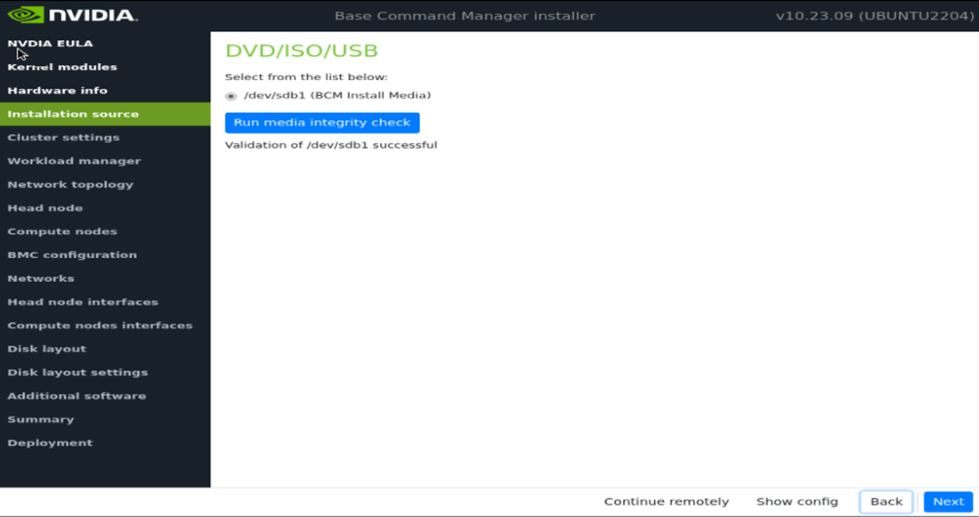
On the Installation source screen, choose the appropriate source and then select Next.
Running a media integrity check is optional.
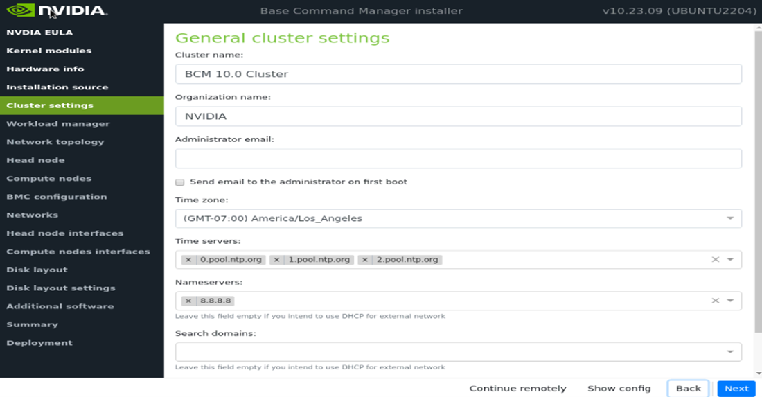
On the Cluster settings screen, enter the required information and then select Next.
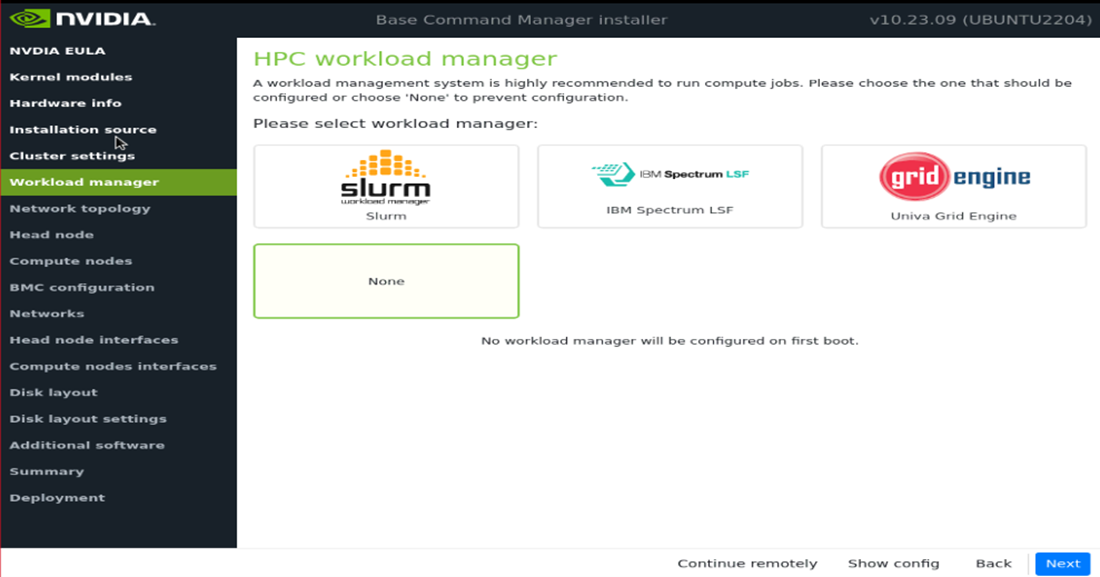
On the Workload manager screen, choose None and then select Next.
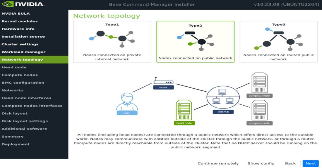
On the Network topology screen, choose the network type for the data center environment and then select Next.
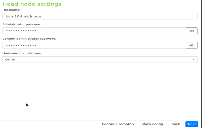
On the Head node screen, enter the Hostname, Administrator password, choose Other for Hardware manufacturer, and then select Next.
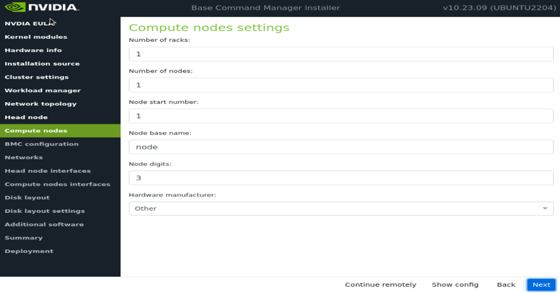
Accept defaults in the Compute nodes and then select Next.
Ensure that the Node base name is node. Other values will be updated later in the installation.
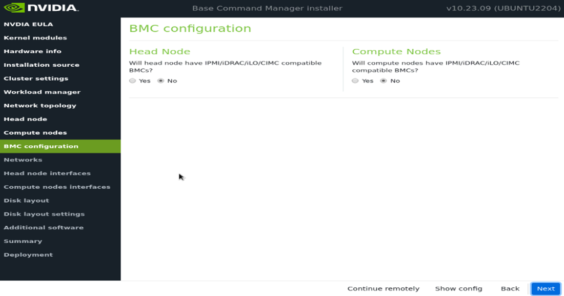
On the BMC Configuration screen, choose No for both Head Node and Compute Nodes, and then select Next.
These will be updated later in the post install stages.
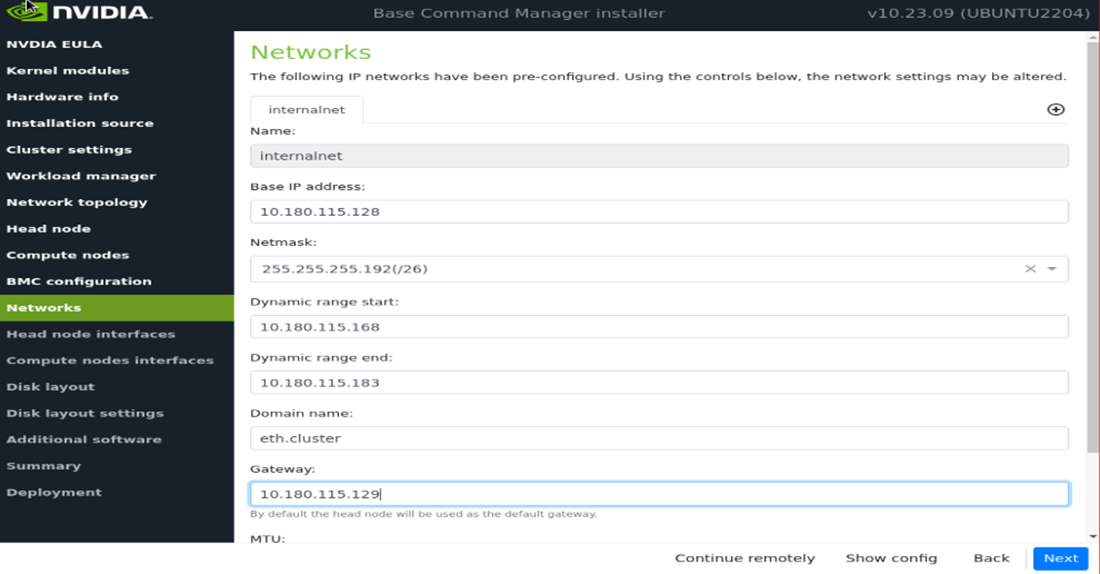
On the Networks screen, enter the required information for internalnet, and then select Next.
Since a Type 2 network was specified, there are no other network tabs (for example, internalnet or ipminet).
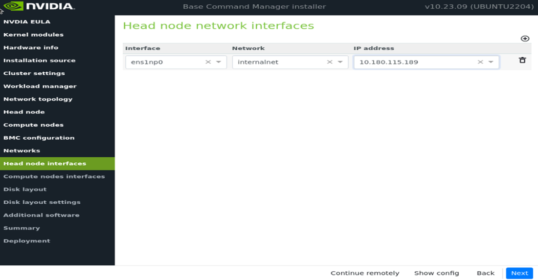
On the Head node interfaces screen, ensure that one interface is configured with the head node’s target internalnet IP, and then select Next.
Other interfaces will be configured by the post install script.
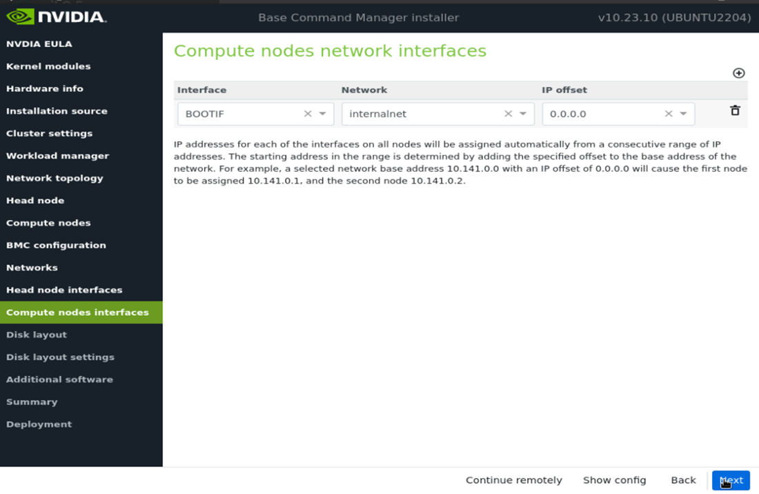
- On the Compute node interfaces screen, leave the default entries, and then select Next.
These will be updated post install.
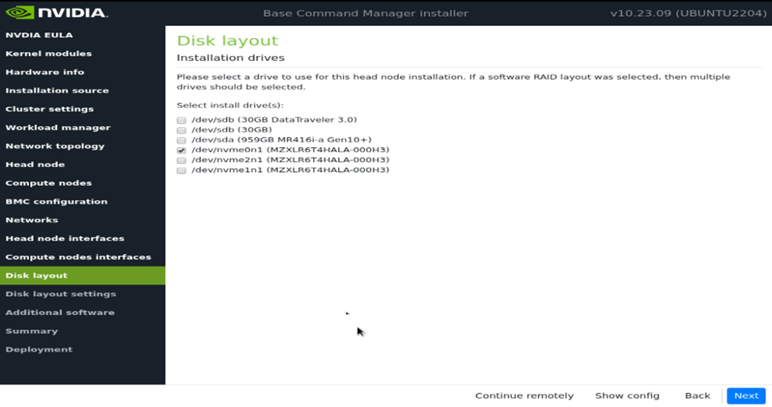
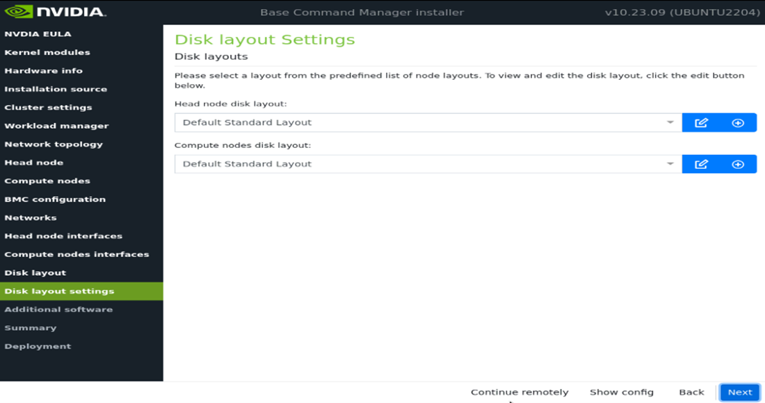
On the Disk layout screen, select the target install location (in this case nvme0n1) and then select Next.
On the Disk layout settings screen, accept defaults and then select Next.
These settings will be updated later in the post installation steps.
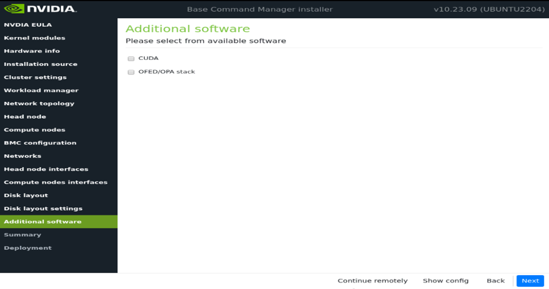
In the Additional software screen, do not choose anything and then select Next.
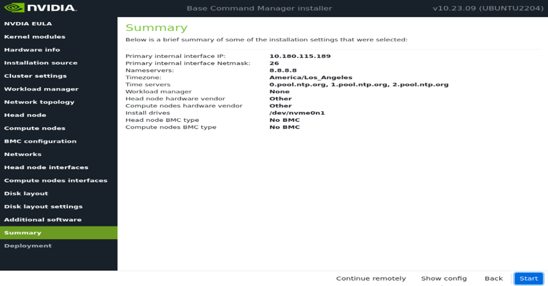
Confirm the information on the Summary screen and then select Next.
The Summary screen provides an opportunity to confirm the Head node and basic cluster configuration before deployment begins. This configuration will be updated/modified for DGX SuperPOD after deployment is complete. If values do not match expectations, use the Back button to navigate to the appropriate screen to correct any mistake.
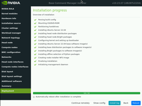
Once the deployment is complete, select Reboot.
License the cluster by running the request-license and providing the product key.
sudo -i request-license
Product Key (XXXXXX-XXXXXX-XXXXXX-XXXXXX-XXXXXX):
Options:
If using the old method of MAC to IP allocation, skip line 32.
If employing the new method: Automatically detect MAC addresses based on switch and switch port, proceed to the next step.
Before advancing with the execution of the network automation application, certain prerequisites are necessary. Do as following:
Copy the “p2p_ethernet.csv” file from the USB stick to the following path
/cm/local/apps/bcm-superpod-network/config/p2p_ethernet.csvmv p2p_ethernet.csv /cm/local/apps/bcm-superpod-network/config/
Load the bcm-superpod-network module.
module load bcm-superpod-network
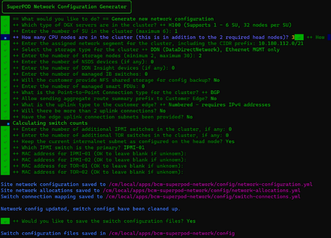
Run the bcm-netautogen script.
bcm-netautogen
Noticed New additional information has been provided.
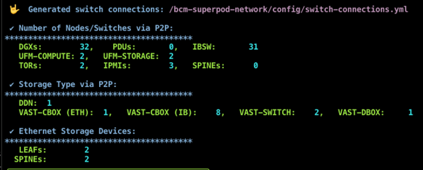
Data was extracted from the p2p_ethernet.csv file to compute the quantities of Network Switches, DGX, IBSW, and PDUs. Accurate values must be provided during menu execution, which will be updated in future releases to utilize the count as physical cable connections.
The following generated files are important and contain data:
Site network configuration - /cm/local/apps/bcm-superpod-network/config/network-configuration.yml
Site network allocations - /cm/local/apps/bcm-superpod-network/config/network-allocations.yml
Switch connection - /cm/local/apps/bcm-superpod-network/config/switch-connections.yml
IP Allocation Readme file - /cm/local/apps/bcm-superpod-network/config/ip_allocations.md
Download and move
cumulus-linux-5.10.0-mlx-amd64.binandimage-X86_64-3.11.2300.imgto the following directory on the head node. Contact your TAM for access to the correct file and move the file to the following directory on the head nodemv cumulus-linux-5.10.0-mlx-amd64.bin /cm/local/apps/cmd/etc/htdocs/switch/image/ mv image-X86_64-3.11.2300.img /cm/local/apps/cmd/etc/htdocs/switch/image/
Load the bcm-post-install module.
module load bcm-post-install/
Run the bcm-pod-setup script.
The parameters to use are:
–C sets the base address of the computenet network.
–S sets the base address of the storagenet network.
–I sets the installation source.
bcm-pod-setup -C 100.126.0.0/16 -S 100.127.0.0/16 -I /dev/sdb
Check the nodes and their categories.
Extra options are used for device list to make the format more readable.
1cmsh
2[bcm-head-01]%device list -f hostname:20,category:10
Result:
1hostname(key)      category
2bcm-cpu-01           default
3bcm-dgx-a100-01.  dgx-a100
4bcm-dgx-h100-01.  dgx-h100
Confirm the config is correct for bcm-dgx-h100-01 / bcm-dgx-a100-01.
 1[bcm-head-01->device[bcm-dgx-h100-01]]% interfaces
 2[bcm-head-01->device[bcm-dgx-h100-01]->interfaces]% list
 3Type         Network device name    IP               Network          Start if
 4------------ ---------------------- ---------------- ---------------- --------
 5bmc          ipmi0                  10.0.92.50       ipminet          always
 6bond         bond0 [prov]           10.0.93.12       dgxnet           always
 7physical     enp170s0f1np1 (bond0)  0.0.0.0                           always
 8physical     enp41s0f1np1 (bond0)   0.0.0.0                           always
 9physical     ibp154s0               100.126.5.14     ibnetcompute     always
10physical     ibp170s0f0             100.127.2.2      ibnetstorage     always
11physical     ibp192s0               100.126.6.14     ibnetcompute     always
12physical     ibp206s0               100.126.7.14     ibnetcompute     always
13physical     ibp220s0               100.126.8.14     ibnetcompute     always
14physical     ibp24s0                100.126.1.14     ibnetcompute     always
15physical     ibp41s0f0              100.127.1.2      ibnetstorage     always
16physical     ibp64s0                100.126.2.14     ibnetcompute     always
17physical     ibp79s0                100.126.3.14     ibnetcompute     always
18physical     ibp94s0                100.126.4.14     ibnetcompute     always
Note
Enabling the CX7 firmware upgrade
To upgrade the mlx firmware , set below flag to ‘yes’. By default, this flag is set to ‘no’. This flag can be changed in the software image.
For example (setting in the softwareimage):
1cat /cm/images/<dgx image>/etc/infiniband/openib.conf | grep RUN_FW_UPDATER_ONBOOT
2
3RUN_FW_UPDATER_ONBOOT=yes
Once set, perform an ipmi tool power off and power on.
Check the Ethernet Switch are in the devices.
cmsh >> device >> list
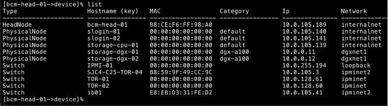
Validate under the Type Switches are added after executing
bcm-pod-setupAdd Switch credential, under each IPMI, TOR and SPINE switch.
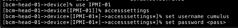
1commit
2quit
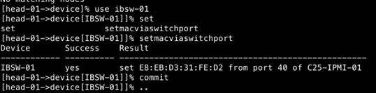
To allocate IP via switch port:
After running bcm-pod-setup, once all the networks, and devices objects are added to the Bright
Make sure the IPMI switch is UP in the Bright before moving to the next step
Based on the switch and switch port configuration for each node, navigate to the device then nodes, and execute the below command:
setmacviaswitchport…… Set the MAC of a device via the MAC found on its switch ports.It will access the switch and pull the MAC address based on the switch port allocation.
To gather UFM metrics
Add UFM to the Bright with mgmt IP address
Make sure UFM Promethus exporter is enable in UFM
 1## You can check by curl command from bright:
 2curl http://<UFM-IP>:9001/metrics
 3
 4## Configure Bright with following:
 5monitoring setup
 6add prometheus UFM
 7set urls https://<UFM-IP>:9001/metrics
 8set –e NoPostAllowed yes
 9nodeexecutionfilters
10active
11commit
12
13## Wait for (~2mins) for data to be collected
14get measurables
15
16## To plot
17monitoring labeledentity
18list
19
20## Using the index value:
21instantquery <index value>