Network Fabrics#
Building systems by SU provides the most efficient designs. However, if a different node count is required due to budgetary constraints, data center constraints, or other needs, the fabric should be designed to support the full SU, including leaf-spine switches and leaf-spine cables, and leave unused the portion of the fabric where these nodes would be located. This approach ensures optimal traffic routing, maintains consistent performance across all portions of the fabric, and preserves the fabric’s ability to scale to its planned size with minimal impact on the existing infrastructure.
DGX SuperPOD configurations utilize the following network fabrics:
Compute (east-west) InfiniBand X-800 fabric
Ethernet (north-south) fabric with the following segments:
Storage network
In-band (control and management) network
Out-of-band (IPMI) network
Figure 6 shows the ports on the back of the DGX RUBIN NVL8 chassis and the connectivity provided. Each DGX RUBIN NVL8 connects to the InfiniBand XDR compute fabric using eight OSFP ports provided by NVIDIA ConnectX-9 SuperNICs.
The high-speed Ethernet ports on the NVIDIA BlueField-4 DPU connect to the Ethernet fabric, providing parallel pathways to prevent single-port failures and increase performance.
In addition, the BMC from both the compute host (DGX node) and the BMC of the NVIDIA BlueField-4 DPU is connected to the out-of-band network for Ethernet management.
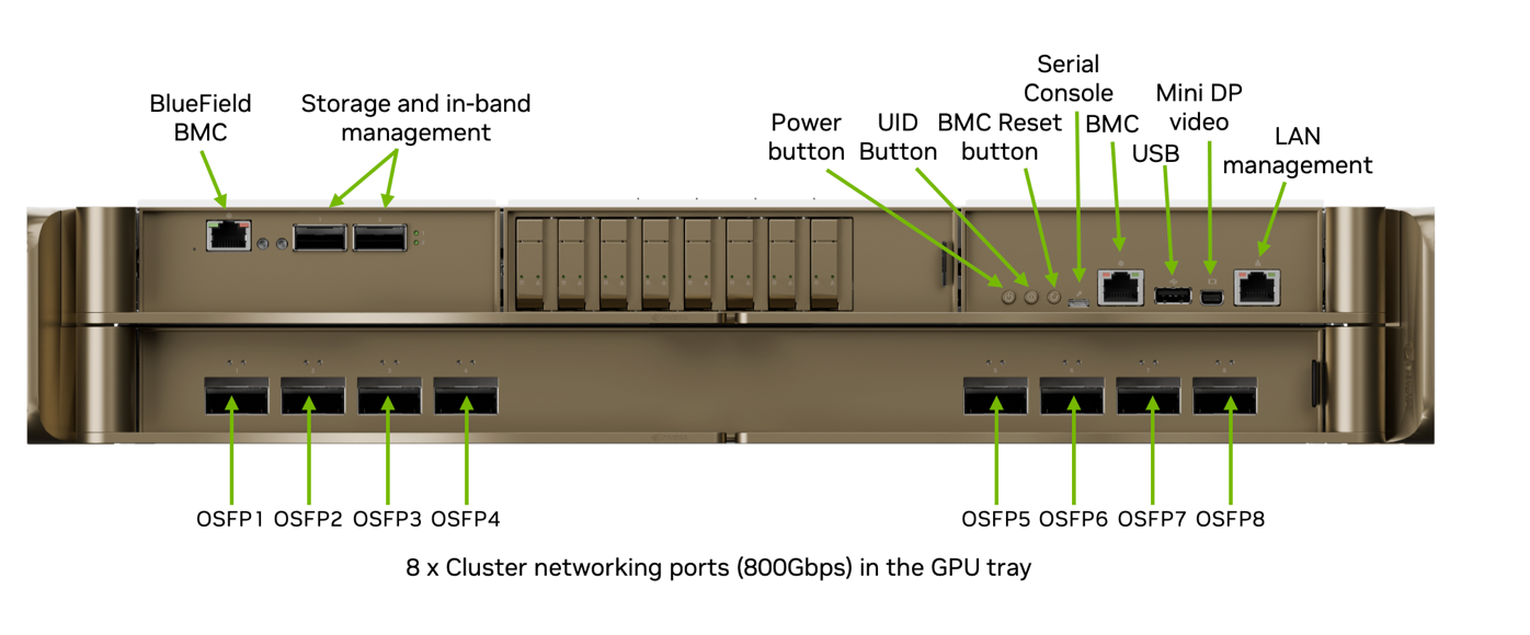
Figure 6 DGX RUBIN NVL8 Network Ports#
Compute Fabric#
Figure 7 shows the compute fabric layout for the full 576-node DGX SuperPOD. Each group of 72 nodes is rail-aligned, with eight rail systems in each SU. Each DGX RUBIN NVL8 connects to the InfiniBand XDR compute fabric using NVIDIA ConnectX-9 adapters, so traffic within one of the eight rails of DGX RUBIN NVL8 systems is always one switch away from the other 71 nodes in an SU. Traffic between SUs or between rails traverses the spine layer. UFM 3.5 nodes are connected to four FNM ports on the Q3400 switches.
NVIDIA BlueField offloads infrastructure work from host CPUs by running hardware-accelerated engines for software-defined networking, storage, and security directly on the DPU. By offloading, accelerating, and isolating networking, storage, and security, BlueField-4 DPUs enhance performance, optimize efficiency, and bolster security.
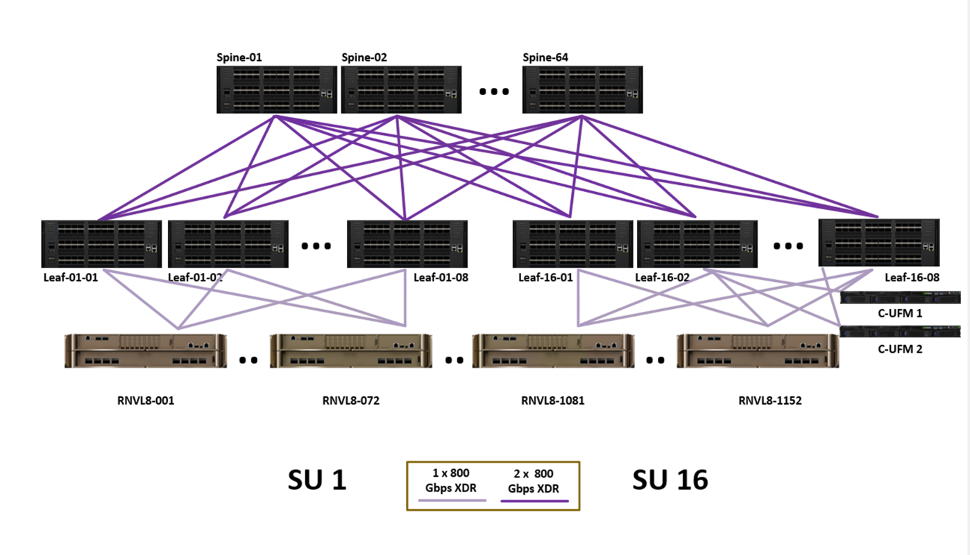
Figure 7 Compute Fabric for Full 1152-Node DGX SuperPOD#
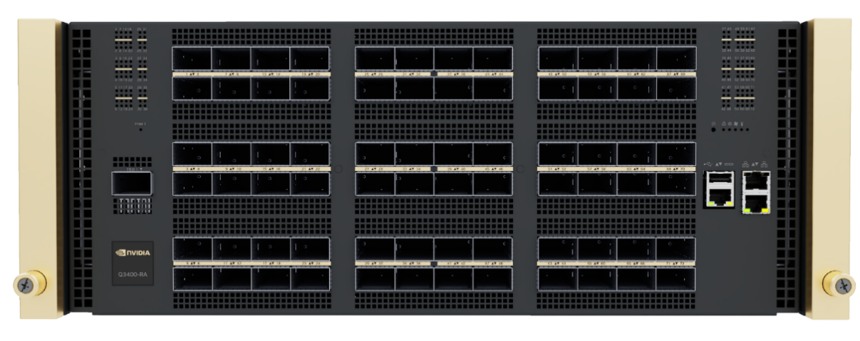
Figure 8 Q3400-RD InfiniBand Quantum-X800 Switch#
Ethernet Fabric#
In the Ethernet fabric design for DGX SuperPOD with DGX RUBIN NVL8, the Ethernet design previously introduced for DGX SuperPOD with DGX GB200/300 NVL72 systems is adopted. This design allows customers to integrate the Rubin GPU platform into existing Blackwell storage and in-band infrastructure to enhance cost efficiency while maintaining the high level of performance required by the storage network in a large-scale AI training and inference cluster.
NVIDIA BlueField-4 DPUs on each DGX RUBIN NVL8 connect to the Spectrum-4 Ethernet storage fabric, providing RDMA-capable, secure access to high-performance storage and control-plane services. In this design, BlueField-4 serves as the host-based network segmentation endpoint for storage and in-band traffic, offloading these functions from the DGX host CPUs and GPUs. The Ethernet fabric uses NVIDIA Spectrum-4 SN5600D Ethernet switches (Figure 9).
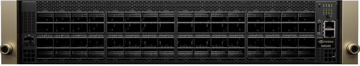
Figure 9 NVIDIA Spectrum SN5600 Ethernet Switch#
DGX RUBIN NVL8 storage connections are designed with 2:3 uplink-to-downlink oversubscription at the DGX storage leaf switches. The total aggregated non-blocking bandwidth for all DGX systems within a single SU is 96 × 400 Gb/s. For a 16-SU design, the total aggregated design bandwidth capacity is 1,536 × 400 Gb/s.
A dedicated storage leaf switch group consisting of two switches, each with up to 64 × 400 Gb/s links, provides support for up to 128 × 400 Gb/s of total storage bandwidth in a non-blocking 1:1 setup for the high-performance storage. This supports per-SU bandwidth of 400 GB/s and is aligned with the enhanced requirements of the recommended storage system. Additional storage leaf switches are supported if higher total bandwidth is required.
A dedicated pair of leaf switches is used to connect all the control-plane nodes and other storage systems such as NFS. A total uplink capacity of 1 × 400 Gb/s per leaf-spine pair is provided to meet performance requirements for provisioning and the control plane while maintaining the cost-performance balance.
The two-layer fabric with 16 spine switches supports a DGX SuperPOD with up to 16 SUs (9,000 GPUs). Additional spines might be required if more storage leaf switches need to be connected.
Finally, the Ethernet fabric is extended by a pair of management leaf switches to connect the persistent home storage and the management nodes, as well as a pair of out-of-band spine switches that connect to the deployed SN2201 OOB switches. Customers should provide a dedicated uplink for the OOB Ethernet network.
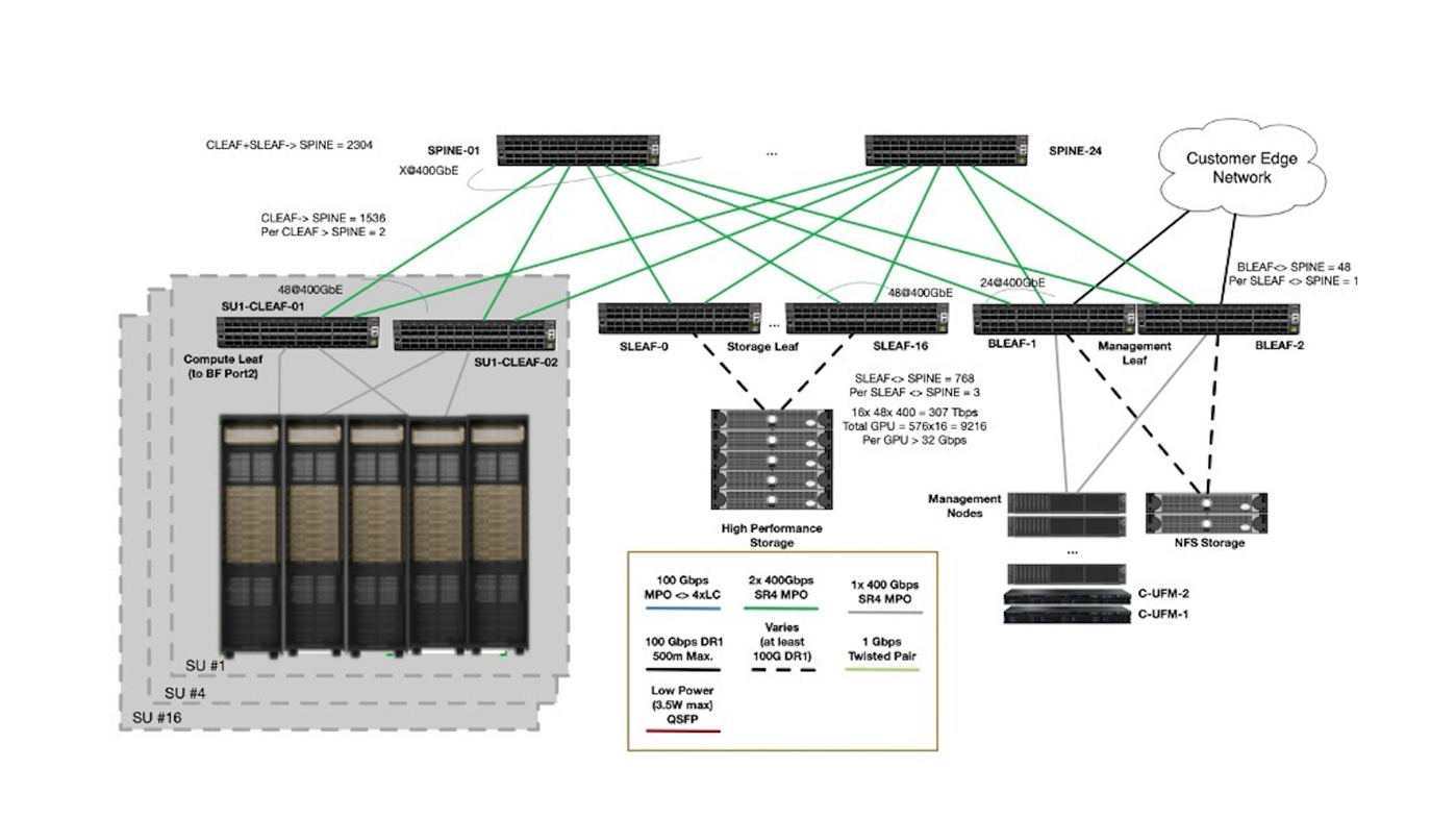
Figure 10 Ethernet Fabric Design#
#GPU |
#SU |
Spines |
Compute Leafs | N/S Mgmt Leafs | N/S Mgmt Spines |
||
|---|---|---|---|---|---|
576 |
1 |
4 |
8 |
4 |
2 |
1152 |
2 |
8 |
16 |
8 |
4 |
2304 |
4 |
18 |
32 |
16 |
8 |
4608 |
8 |
36 |
64 |
32 |
16 |
9216 |
16 |
72 |
128 |
44 |
32 |
Network Segmentation of Ethernet Fabric#
The Ethernet fabric is segmented into these segments on the DGX SuperPOD:
Storage Network
In-band Network
In addition, a dedicated OOB management network is provided as an Ethernet network to give administrators a secondary access path.
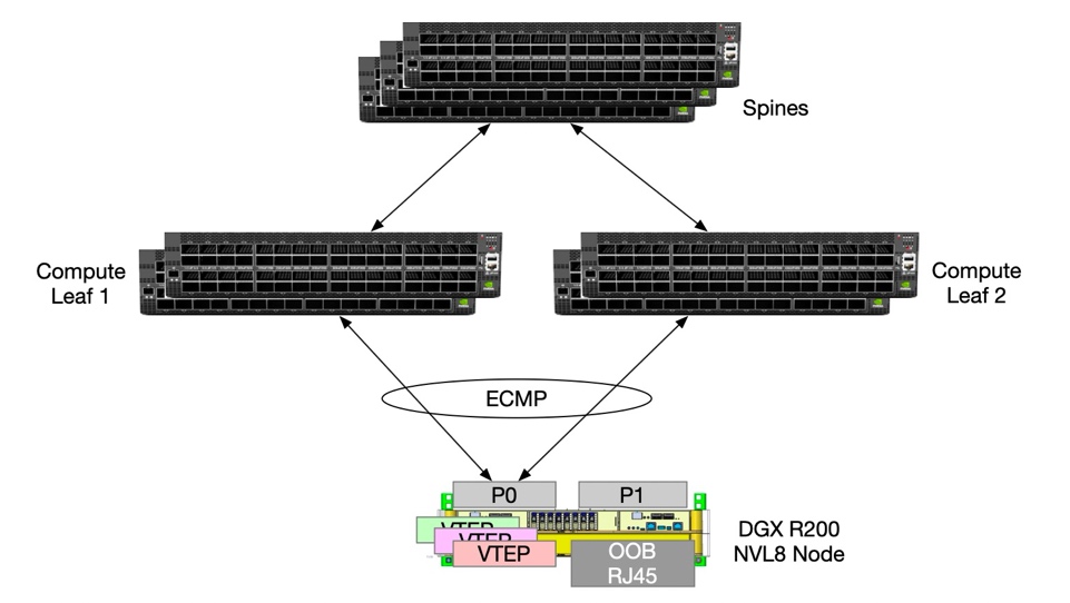
Figure 11 Network Segmentation Diagram#
In DGX SuperPODs, the Ethernet fabric is a Layer 3 (L3) routed network. The L3 routed network with Ethernet Virtual Private Network Multihoming (EVPN-MH) is the reference design for high availability and efficiency in modern data centers. Compared with legacy Layer 2 (L2) networking designs such as Multi-Chassis Link Aggregation (MLAG), EVPN-MH allows hosts to connect to multiple switches simultaneously using an all-active path.
A major improvement over the previous generation is the enablement of HBN to address the need for high availability (HA) for each individual DGX system. In this design, NVIDIA BlueField-4 DPUs provide the HBN interface for each DGX RUBIN NVL8, connecting it redundantly to multiple Spectrum-4 leaf switches using EVPN multihoming for all-active paths and fast failover.
The Ethernet fabric features an underlay network based on external Border Gateway Protocol (eBGP) and a Virtual Extensible Local Area Network (VXLAN)-based data plane. The core mechanism is the Ethernet Segment Identifier (ESI), a unique 10-byte ID assigned to the links connecting a multihomed device to multiple leaf switches. Because the fabric recognizes the same ESI across different leaves, it treats them as a single logical entity. This enables all-active load balancing, allowing traffic to be distributed through Equal-Cost Multi-Path (ECMP) using 5-tuple hashing across the entire fabric, without requiring a direct physical inter-switch link (ISL) cable between the switches.
This results in a highly scalable architecture that maximizes bandwidth and provides sub-second failover, with an effectively unlimited number of spine and leaf switches in the Ethernet fabric. NVIDIA Spectrum-4 switches are designed with full support for EVPN-MH and provide high performance for both RDMA and standard traffic in the overlay network.
Storage and In-Band Network#
The Storage and In-Band Network design describes how storage and in-band management traffic are carried over the Ethernet fabric in DGX SuperPOD deployments, including the role of NVIDIA BlueField-4 DPUs and the logical separation of these traffic types.
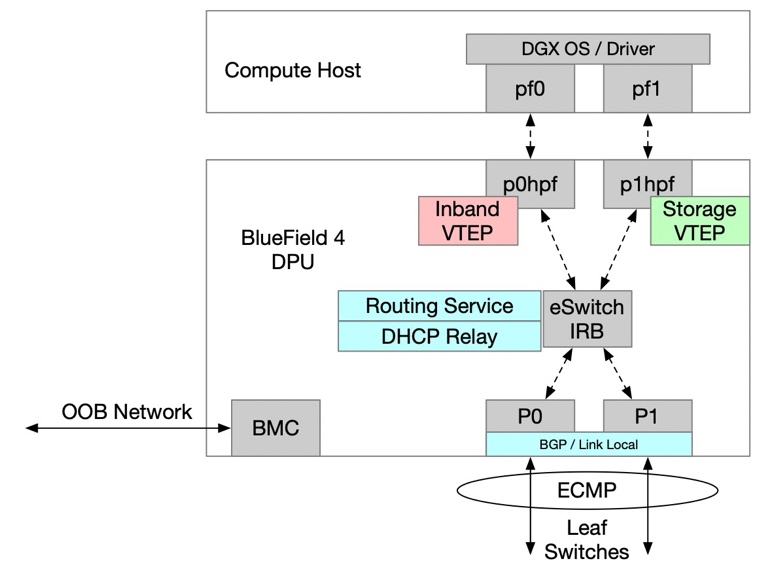
Figure 12 HBN Configuration Diagram#
To provide high availability and up to 800 Gb/s of Ethernet throughput on the NVIDIA BlueField-4 DPU, the SuperPOD design uses VXLAN overlays across the Ethernet fabric for storage, in-band, and out-of-band networks. This logical overlay approach isolates higher-priority storage traffic from other control-plane and management flows while still sharing a common physical network.
In addition, this design has the benefit that the compute host sees only a single interface for in-band traffic and a single interface for storage traffic. This is aligned with previous generations of DGX GB200/300 SuperPOD systems and allows easier adoption for customers moving to the new platform.
For high-performance storage access, RoCEv2 is used as the communication protocol to meet the performance requirements for storage access.
The in-band management network provides several key functions:
Connects all the services that manage the cluster.
Enables access to the lower-speed NFS tier of storage.
Provides uplink (border) connectivity for in-cluster services, such as Mission Control, BCM, Slurm, and Kubernetes to services outside the cluster, such as the NGC registry, code repositories, and data sources.
Provides end users with access to the Slurm head nodes and Kubernetes services.
Out-of-Band Management Network#
The OOB management network provides a physically and logically isolated path for managing all DGX SuperPOD infrastructure components, independent of the production data and control-plane networks.
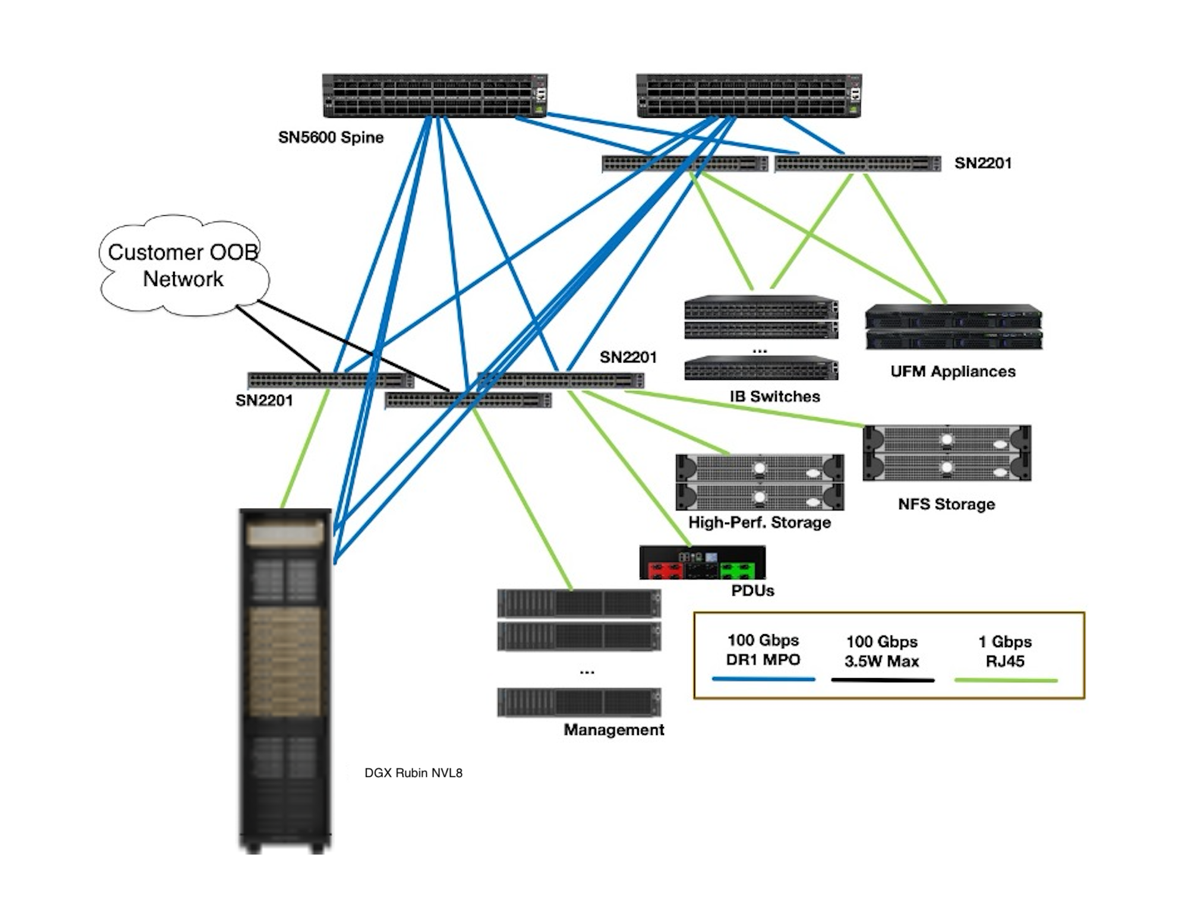
Figure 13 Schematics for the Out-of-Band Network#
The OOB management network carries all Intelligent Platform Management Interface (IPMI)-related control traffic. It connects the management ports of all devices, including DGX RUBIN NVL8 compute nodes (both the BlueField-4 BMC and the DGX system BMC), InfiniBand and Ethernet switches, management servers, storage appliances, rack Power Distribution Units (PDUs) and power shelves, and all other devices that are part of the SuperPOD and support OOB management. These devices are separated onto their own network, with dedicated, separate uplinks that provide a parallel path into the SuperPOD for disaster recovery and management purposes.
The OOB network is rolled up into the aggregation layer (spine layer) of each SU as a dedicated VXLAN. The OOB management network uses SN2201 switches as top-of-rack (TOR) switches (shown in Figure 14) and SN5600D switches as spine switches. Like the Ethernet fabric, the OOB network is also an L3 routed design, which means that the spines are aggregated using EVPN-multihoming technology.
There is no use case in which a non-privileged user needs direct access to these ports, and they are secured using logical network separation.
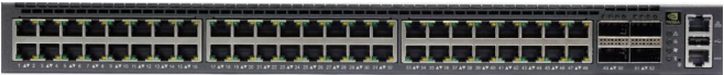
Figure 14 SN2201 Switch#
Customer Edge and NFS Connectivity#
There are three customer-provided components for connectivity into the DGX SuperPOD:
NFS home storage
Main uplink, carrying the default route
OOB uplink, for management purposes only
For route handover, Border Gateway Protocol (BGP) is prepared to peer with the customer’s network. Routes to and from the in-band and out-of-band networks are announced. Furthermore, the default route is announced or learned on the main uplink.
Because of power and physical-layer (PHY) connectivity limitations on the leaf switches, the recommended optical modules are:
For SN5600: DR1 LC or DR4 MPO, or any other supported transceiver
For SN2201: any supported QSFP transceiver that does not require more than 3.5 W of power
Customers who cannot provide this supported connectivity are encouraged to use a pair of dedicated border leaf switches to expand the available optical connectivity options (not as part of the SuperPOD).
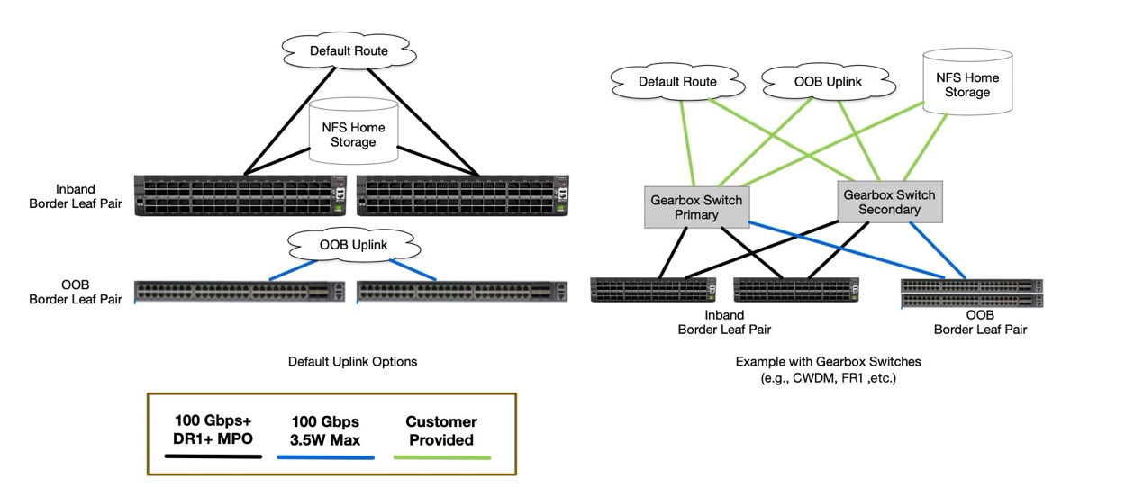
Figure 15 Customer Edge Example#
For the operation with DGX SuperPOD, customers are required to provide NFS-based home storage and configuration storage, to be integrated with NVIDIA Mission Control.
SuperPOD with DGX RUBIN NVL8 supports storage integration with single-mode DR1 (or compatible 100 G SerDes) connectivity for user storage. User storage is connected to the leaf-layer SN5600D switches.