Virtualized System Configuration
Virtual machines are emulated on a physical machine with each virtual machine having a subset of resources available on the physical machine. The NVIDIA Virtualization System is highly configurable, allowing every system to address different use cases and requirements for unique configuration.
This document describes the fundamentals of NVIDIA Virtualization System configuration and provides procedures for configuring virtual machines.
This document includes the following sections:
• Partition Configuration Table (PCT) concepts
• PCT Structure (Files, Naming, and other considerations)
• Assignment of Virtual Machine (VM) resources
Partition Configuration Concepts
This section discusses the Partition Configuration Table (PCT), peripherals, and how they are used together
Partition Configuration Table
The Partition Configuration Table (PCT) is a proprietary mechanism for configuration of virtual machines according to NVIDIA Virtualization System requirements.
The PCT consists of the following components and characteristics:
• Syntax for expression of virtual machine configurable attributes.
• Configuration files to hold virtual machine attributes for a platform.
• Host tools to convert human-readable configuration information into the PCT Binary Blob format that can be consumed by the runtime virtualization system components.
• A library (the PCT Parsing Library) for parsing the PCT binary blob and extracting the configuration information. This library is supported for both the host and the target.
Peripherals
The NVIDIA Tegra SoC consists of many sub-blocks. A set of sub-blocks comes together to provide desired high level functionality. In-depth knowledge of each of the sub-blocks and relationships between them is required to be able to assign a high level functionality to the virtual machine. To hide some of this complexity, the NVIDIA Virtualization System defines the concept of a peripheral.
A peripheral is a separately assignable computer system component. A peripheral may, for example, comprise such things as a collection of MMIO ranges, interrupt signals, power controls, clock controls, and/or reset controls.
Physical peripherals are peripherals in a physical machine. The NVIDIA Virtualization System refers to all peripherals assigned to a virtual machine as virtual peripherals.
Peripherals are related to device tree nodes that encapsulate all resources that a device driver requires to operate. A peripheral provides one more level of abstraction, encapsulating multiple device tree nodes.
Peripheral Variants
There are two categories of peripheral:
• Passthrough peripherals
• Shared peripherals
Passthrough Peripherals
Passthrough peripherals must be accessible by only one virtual machine. Once assigned to a virtual machine, virtual passthrough peripherals expose the exact same interface to the Guest OS as is exposed by a physical peripheral.
The PCT identifies each passthrough peripheral with a unique peripheral ID.
Shared Peripherals
Shared peripherals support mapping of more than one virtual peripheral to one physical peripheral. Each virtual peripheral is an instance of the physical peripheral, usually with a subset of the capabilities supported by the physical peripheral. Each virtual peripheral is independent and meets NVIDIA Virtualization System isolation requirements.
NVIDIA Virtualization System uses the following mechanisms for implementing virtual peripherals:
• Hardware-assisted virtualization
• Para-virtualization
• Emulation
• A mix of the above
Unlike passthrough peripherals, the hardware interface exposed by this class of peripheral to the Guest OS can be different from interfaces exposed by physical peripherals.
The NVIDIA Virtualization System does not distinguish between virtual peripherals based on the implementation mechanisms listed above. Other sections of this documentation describe the implementation mechanism for a virtual device to explain the configuration parameters.
Peripheral Assignment
Assignment of a virtual peripheral to a virtual machine maps the virtual peripheral resources, such as MMIO, IRQ, Clocks, and IVC interface, to the virtual machine.
The PCT provides a very simple configuration interface for assignment of passthrough peripherals to the virtual machine. This section describes the exact syntax for assignment of passthrough peripherals.
The PCT Peripheral Ownership data structure holds the assignment configuration, shown below:
Assignment Option | Description |
GUEST_HYP | (Hypervisor owned.) This assignment option implies that PCT peripheral access is emulated by the hypervisor. PCT peripheral assignment must not change for PCT peripherals with the GUEST_HYP option configured. |
GUEST_<ID> | (Guest owned.) This assignment option provides passthrough access from the PCT peripheral to the guest. |
UNASSIGNED | This assignment option implies that the PCT peripheral is not accessible from any of the VS elements. Select this option for PCT peripherals that are not applicable for the system. |
GUEST_HYP | GUEST_<ID> | This assignment option indicates that access to the PCT peripheral is trapped by the hypervisor and actual access is performed by the hypervisor. From the perspective of the guest, access functions like passthrough access. Use this type of assignment where it is not safe to provide passthrough access from the PCT peripheral to the guest. The GUEST_<ID> can be changed, but GUEST_HYP must be retained. |
Peripheral assignment is shown in the following example (from guest_io_periph_assign.h.):
struct guest_io_mapping io_ownership [] __attribute__ ((section("io_owner"))) = {
IO_OWNERSHIP(TEGRA_PCIE_APERTURE, LINUX ),
IO_OWNERSHIP(TEGRA_VIC, VM_SERVER ),
IO_OWNERSHIP(TEGRA_AON_PMC, HYPERVISOR ),
IO_OWNERSHIP(TEGRA_AXIS_NIC, UNASSIGNED ),
Shared Peripheral Assignment
Assignment of shared peripherals is a two-step process:
1. Instantiation of one or more virtual peripherals mapped to physical peripherals. Instantiation involves assigning a subset of physical peripheral capabilities to virtual Peripherals.
2. Actual mapping of instantiated virtual peripherals to the virtual machine.
The PCT describes the capabilities associated with virtual peripherals and allows you to assign capabilities and instantiate a virtual peripheral. Because each peripheral is different, the capabilities described in the PCT for each shared peripheral are different. An understanding of the basic functionality provided by shared peripherals is needed to be able to assign capabilities and instantiate a virtual peripheral.
See
Shared Peripheral Configuration in this chapter for details on PCT description for each shared peripheral.
PCT Virtual Peripheral Interface
Virtual peripherals implemented using the para-virtualization mechanism use the PCT-defined concept of a virtual peripheral interface, referred to as VInterface.
Normally the software interfaces with the peripheral using a register interface, but in cases where a virtual peripheral is implemented using a para-virtualization mechanism, the physical hardware is managed by the server partition. The server partition exposes an IVC channel-based interface for the driver running in the guest. The definition of the resulting pool of IVC channels is the VInterface.
PCT Virtual Machine ID
The primary purpose of the PCT is assigning virtual peripherals to the virtual machine. The PCT allocates a unique identifier for each virtual machine. This allows NVIDIA Virtualization System to derive virtual peripheral ownership from the PCT blob. and based on that, assign the virtual peripherals to the virtual machine.
Instead of explicitly assigning an ID, the PCT auto-generates an ID based on the index with which the virtual machine is listed in the gconf data structure.
PCT Privileges
NVIDIA Virtualization System defines the concept of privileges, allowing the virtual machine to perform operations outside regular container boundaries. The PCT provides mechanisms to assign these privileges to virtual machines.
PCT Characteristics
The following sections describe specific PCT characteristics.
PCT Structure
PCT configuration belongs to a specific platform, consisting of the SoC and the board. It is possible to have multiple PCT configurations for a platform. Each such configuration is an independent product based on that particular platform.
PCT Naming
Typically, all PCTs supported for a particular platform are kept in the same location. The naming convention followed for that location is <board>-<soc>, for example, p2382-t186. The naming of each PCT configuration folder contained in the platform folder is not rigid. Typically the name represents the Guest OS that is part of that PCT configuration.
Example
(pct/p2382-t186/linux-linux) This is a PCT for the NVIDIA DRIVE™ CX 2 platform, based on the NVIDIA® Tegra® Code-Name Parker processor, that implements a dual-Linux system.
PCT Files
PCT configuration data is populated in the following header files.
guest_config.h
This configuration file contains configuration required for creation of virtual machine and also assigns virtual devices to the virtual machine. Each entry in the guest_conf array instantiate a virtual machine. Each member of guest_conf structure specifies attributes, privileges or resources assigned to the virtual machine.
platform_config.h
This configuration file contains configuration for 1. CPU/vCPU Assignment to virtual machine. 2. IVC Channels between virtual machines. 3. mempools or shared buffers between virtual machines.
guest_io_periph_assign.h
This file contains configuration required for pct peripheral to virtual machine assignment.
guest_gpio_ownership.h
This configuration file contains GPIO pin assignment to Virtual GPIO Controller.
guest_i2c_ownership.h
This configuration file contains configuration for i2c slave assignment to Virtual I2C Controller.
global_storage.cfg
This configuration file describes the storage layout for virtual machines. It constructs storage containers.
linux1_storage.cfg
This configuration file describes the storage layout within virtual machines storage container.
common.h
This file associates macros to map Guest ID to more readable macros.
Building the PCT
After changes are made in the PCT, it is necessary to compile the PCT and generate the PCT blob. The PCT blob is part of the NVIDIA DRIVE™ Foundation image, and the Foundation image must be regenerated with the newly created PCT blob. The bind_partitions tool is used to generates the PCT blob and the Foundation image.
PCT Library
NVIDIA Virtualization System implements APIs that allow VS elements to extract configuration information by parsing the PCT blob. This library is implemented for both the ARM and the X86 architectures, allowing both host and target software to parse the PCT blob.
Shared Peripheral Configuration
This includes the procedure to configure shared peripherals for instantiation of virtual peripheral mapping to the shared peripherals. You can instantiate virtual peripherals with a subset of capabilities supported by physical peripherals and assign the virtual peripheral to a virtual machine.
Virtual RAM
Memory (system DRAM) is used to store code and data for computer programs, and generally it is directly accessible by the CPU and sometimes also by peripheral devices.
Virtual RAM is RAM that is private to the virtual machine and is not shared with other virtual machines.
The virtualization system uses several mechanisms including the Memory Management Unit (MMU) and the System Memory Management Unit (SMMU) to partition memory between virtual machines. The MMU and the SMMU form the foundation of the trusted computing base for the system.
Configuration
Virtualization system configuration provides PCT parameters to allocate virtual RAM. This section describes these parameters. The amount of physical memory available to each VM (virtual RAM) is determined by a fixed (base) amount plus a dynamic (growth) amount. The value for the fixed amount is read directly from the PCT. The value for the dynamic amount is based on the amount of memory left over after the fixed allocation and subsequently assigned to each virtual machine based on a per-VM growth factor. Higher growth factors result in a higher proportion of memory given to a VM.
Apart from virtual machines there are many other components that consume RAM, including NVIDIA Virtualization System, auxiliary processors, and protected carveouts. The amount of RAM available to the virtual machine is subject to memory consumed by these components.
PCT Configuration
The guest_conf struct’s members guest_phys_mem_size and guest_phys_mem_growth_factor describe fields used for guest memory configuration. For example:
/*
* The GUEST_ATTR macro is defined in common.h.
*/
.guest_phys_mem_size = GUEST_ATTR(GID_LINUX, PHYS_MEM_SIZE),
.guest_phys_mem_growth_factor =
GUEST_ATTR(GID_LINUX, GROWTH_FACTOR),
Virtual CPU
A physical CPU or PCPU is a computer system component that executes a serial stream of instructions.
Each instance of a CPU can be considered as a single hardware thread of execution. On a Tegra SoC multiple CPUs are available, manifesting the concept of symmetric multiprocessing (SMP).
A virtual CPU or VCPU is an emulated physical CPU. The operation of a physical CPU can be subdivided into one or more virtual CPUs. Each instance of a VCPU can be considered as a single software thread of execution. Only one VCPU can be executing on a given physical CPU at any time, so multiple VCPUs mapped to one physical CPU are achieved with time-sharing. NVIDIA Virtualization System configuration defines the following configurable attributes for a VCPU:
• VCPU affinity to physical CPU
• VCPU priority
• VCPU timeslice
Restrictions
• Priority and timeslice for all the VCPUs belonging to a guest must be the same.
• NVIDIA Server partitions have the highest priority.
• Affinity of VCPUs mapped to an NVIDIA Server must not be changed without consulting the NVIDIA Customer Engineering Team.
Virtual CPU Configuration
The vcpu_conf struct describes fields used for VCPU configuration. For example:
/*
* The VCPU_CONF macro is defined in platform_config.h.
*/
.vcpus = {
[0] = VCPU_CONF(GID_LINUX, DENVER_0, 1),
[1] = VCPU_CONF(GID_LINUX, DENVER_1, 1),
[2] = VCPU_CONF(GID_LINUX_VM2, A57_0, 1),
[3] = VCPU_CONF(GID_LINUX_VM2, A57_1, 1),
[4] = VCPU_CONF(GID_LINUX_VM2, A57_2, 1),
[5] = VCPU_CONF(GID_LINUX_VM2, A57_3, 1),
[6] = VCPU_CONF(GID_BPMP_SERVER, A57_2, 0),
[7] = VCPU_CONF(GID_VM_SERVER, A57_3, 0),
[8] = VCPU_CONF(GID_WDT_SERVER, A57_3, 0),
[9] = VCPU_CONF(GID_I2C_SERVER, A57_1, 0),
[10] = VCPU_CONF(GID_SYSMGR_SERVER, DENVER_0, 0),
[11] = VCPU_CONF(GID_VSC_SERVER, A57_1, 0),
[12] = VCPU_CONF(GID_SE_SERVER, A57_1, 0),
},
Virtual DMA
This section describes virtual DMA controllers and the PCT syntax for their definition and assignment.
DMA Controller
NVIDIA Tegra SoCs support general purpose DMA controllers known as GPCDMA. The DMA controller supports multiple DMA channels. (See the Tegra Technical Reference Manual (TRM) for details.) Each channel can be hooked at runtime to a DMA slave, such as I2C, SPI, or UART. Channels are unidirectional, and two are required for bidirectional use cases.
Virtual DMA Controller
A virtual DMA controller is analogues to a physical DMA controller with the exception that the number of DMA channels available is less than or equal to total number of channels supported by a physical DMA controller. Each virtual DMA controller is assigned to a virtual machine.
Virtual DMA Controller Count
A maximum of eight virtual DMA controllers are supported. The sum of all DMA channels across all virtual DMA controllers must not exceed the channel count supported by the DMA controller.
Virtual DMA Resources
Virtual DMA controllers comprise the following SoC resources:
• MMIO address space for DMA channels
• An interrupt for each DMA channel
• One SMMU Stream ID for each virtual DMA controller
Virtual DMA Controller Configuration
Virtual DMA controller configuration describes the virtual DMA controller and assignment of the virtual DMA controller to a virtual machine. The virtual DMA controller is described in terms of the number of DMA channels it supports. The configuration abstracts the low level resources listed above and provides a very simple configuration interface. Internally the virtualized system uses this information to map internal DMA resources to the virtual machine. Configuration is specified in PCT and the Device Tree for the guest OS. Both must remain in sync for correct functioning of the system.
PCT Configuration
The gpcdma_conf struct’s members chan_start_idx and nr_chan describe the virtual DMA controller in the PCT, as shown in the following example:
/*
* This configuration creates a virtual dma controller which
* implements 16 dma channels. This Virtual DMA Controller
* will map to channel 0 to 16 of physical dma controller.
*
* Every Virtual DMA Controller is assigned a unique
* stream-id TEGRA_SID_GPCDMA_0 from the stream id pool
* TEGRA_SID_GPCDMA_0 - TEGRA_SID_GPCDMA_7
*/
.gdmaCfg = {
.chan_start_idx = 0,
.nr_chan = 16,
.stream_id = TEGRA_SID_GPCDMA_0,
},
Device Tree Configuration
The virtual DMA controller presents the exact same interface to the guest as a non-virtualized DMA controller. This enables the guest to use the same device drivers as it would use in a non-virtualized system.
\snippet tegra186-vcm31-p2382-010-a01-00-base-vm1.dts gpcdma dt example
Virtual GPIO
This section introduces the concept of a virtual GPIO controller and explains the PCT syntax to assign GPIO pins to the virtual machine.
Physical GPIO Domain
The set of physical GPIO pins within any single physical GPIO controller form a physical GPIO domain.
Virtual GPIO Controller
A virtual GPIO controller is a virtual device that behaves the same as a physical GPIO controller except that some of the virtual GPIO pins within the virtual GPIO controller are not implemented. Reads from unimplemented virtual GPIO pin registers yield predefined values, writes are ignored, and all such accesses may cause the virtual machine to encounter a fatal error. Each virtual GPIO controller is said to be mapped to its corresponding physical GPIO controller.
A maximum of eight virtual GPIO controllers are supported per physical GPIO controller, meaning that a maximum of eight virtual machines can access a physical GPIO controller.
Virtual GPIO Domain
The set of virtual GPIO pins within any single virtual GPIO controller form a virtual GPIO domain.
GPIO Logical Pin Numbers
The NVIDIA® Tegra® SoC supports multiple instances of the GPIO controller. Each GPIO controller further has many ports, and each port has a variable number of pins. To facilitate abstraction, all GPIOs are grouped in logical banks (i.e. TEGRA_GPIO_BANK_ID_A, TEGRA_GPIO_BANK_ID_B, and so on). Each bank contains exactly eight GPIO pins.
The NVIDIA® Tegra® TRM expresses the GPIO pins in exactly the same format, which makes it very easy for system integrator to identify GPIO pins.
NVIDIA Virtualization System identifies each GPIO pin using a unique number referred to as GPIO logical pin number. PCT provides a macro to convert a “logical bank, pin” tuple to logical GPIO number:
TEGRA_GPIO(TEGRA_GPIO_BANK_ID_*, pin)
Virtual GPIO Controller Configuration
For simplicity, the GPIO controller is not exposed in the configuration. The virtualized system automatically allocates and assigns a virtual GPIO controller to a virtual machine if one or more GPIO pins belonging to a physical GPIO controller are assigned to a virtual machine.
The guest_gpio_mapping struct’s GPIO member describes the PCT syntax for GPIO pin to VM assignment, as shown in the following example:
/*
* File: guest_gpio_ownership.h
*
* This example shows gpio pin (M,5) assignment to LINUX VM1 &
* (P, 3) assignment to LINUX VM2.
*/
struct guest_gpio_mapping gpio_ownership [] __attribute__ ((section("gpio_owner"))) = {
GPIO_OWNERSHIP(TEGRA_GPIO(TEGRA_GPIO_BANK_ID_M, 5), LINUX),
GPIO_OWNERSHIP(TEGRA_GPIO(TEGRA_GPIO_BANK_ID_P, 3), LINUX_VM2), /* SDCARD_3 */
No special device tree configuration is required. Make sure that the physical GPIO controller device node is enabled in the guest device tree.
Virtual I2C
This section describes the concept of a virtual I2C controller, and PCT configuration syntax for defining a virtual I2C controller and assigning it to a virtual machine.
Virtual I2C Controller
The virtual I2C controller is implemented in software that allows the physical I2C bus to be accessible from multiple virtual machines. The virtual I2C controller implements only a part of the physical I2C bus. This design allows the physical I2C bus to be partitioned between virtual machines. The virtual I2C controller is implemented using a para-virtualization mechanism. NVIDIA Virtualization System implements a Server partition that controls the physical I2C hardware and exposes I2C services using a proprietary interface to the Guest OS I2C driver provided as part of the virtualization system. NVIDIA Virtualization System refers this server partition I2C Server.
Virtual I2C Use Case
An I2C bus can have more than one slave. The system may require distribution of these slaves among virtual machines. In such a scenario NVIDIA Virtualization System allows I2C Server to manage the physical bus and provide para-virtualized access to one or more guest OS.
I2C Configuration
Configuring I2C is a two-step procedure:
• I2C Physical Bus Assignment
• I2C virtual device definition
I2C Physical Bus Assignment
NVIDIA Tegra supports multiple I2C buses. Virtualization System configuration allows any I2C bus to be either directly assigned to the virtual machine as
Passthrough peripherals or assigned to I2C Server to allow sharing of the bus and I2C between virtual machines.
Here is an example of PCT configuration:
/*
* File: guest_io_periph_assign.h
*
* This example shows assignment of TEGRA_I2C_3
* controller to I2C Server for para-virtualized
* i2c services & TEGRA_I2C_4 to LINUX VM in
* pass through mode.
*/
IO_OWNERSHIP(TEGRA_I2C_3, I2C_SERVER ),
IO_OWNERSHIP(TEGRA_I2C_4, LINUX ),
I2C Virtual Device Definition
Virtual I2C Controller Configuration involves two steps:
1. Instantiate the I2C virtual device interface
2. Assign I2C slaves to instantiated virtual I2C peripherals.
Note: | Virtual I2C controller configuration is not applicable to I2C controllers configured as passthrough peripherals. |
I2C Virtual Device Interface
The virtual I2C controller implementation uses the NVIDIA Virtualization System IVC mechanism for low level communication between I2C Server and the guest driver. There is one IVC channel per controller between the server and each guest using I2C Server.
PCT Configuration
/*
* This configuration defines the Virtual I2C device
* interface for VM. This Interface is used by
* Guest OS for using para-virtualized i2c services.
*/
.i2c_server_cfg = {
.vinterface = {
.queues = RESOURCE_POOL(53, 1),
},
},
Device Tree Configuration
/*
* File tegra186-vcm31-p2382-010-a01-00-base-vm1.dts
*
* Virtual I2C Controller uses the same device tree node
* as the Physical I2C Controller.
* Overriding two properties to make the node compatible
* with the Virtual I2C Controller requirements.
* compatible - override to use the virtualized driver.
* ivc_queue - Add this property to select the IVC channel
* based Virtual interface listed for this guest in PCT.
* Refer to PCT VInterface Section for details.
*/
i2c@3180000 {
compatible = "nvidia,tegra186-i2c-hv";
ivc_queue = <&tegra_hv 53>;
};
I2C Slaves Assignment
The guest_i2c_mapping struct’s controller, slave, owner, and __padding members contain I2C assignment information. They describe assignment of I2C slaves to the virtual I2C controller. For example:
/*
* File: guest_gpio_ownership.h
*
* The example assigns slave address 0x68 on I2C_5 bus VM0.
* Also it makes VM0 as the default owner for all the slaves not
* explicitly listed.
*/
struct guest_i2c_mapping i2c_ownership [] __attribute__ ((section("i2c_owner"))) = {
I2C_OWNERSHIP(TEGRA_I2C_5, 0x68, VM0),
/* Assign vm0 as the default vm */
I2C_OWNERSHIP(TEGRA_MAX_DEV, 0, VM0),
Virtual Hardware Synchronization Primitives (HSP)
The Tegra HSP block allows multiple processors to share resources and communicate together. These synchronization elements are reserved for software level inter-processor synchronization and messaging, especially between different ARM processors.
The HSP block encapsulates multiple hardware synchronization primitives:
• Doorbells: a set of source agents in the Tegra SoC to request the attention of a specified target agent. Here source and target are different R5 clusters in the Tegra SoC.
• Shared Mailboxes: A mailbox allows for data exchange and notification between source and destination. Mailboxes are used as pairs for bidirectional communication between two agents.
There are several HSP blocks. Each block is part of one of the CPU clusters.
The HSP instances are:
• TOP1 HSP and TOP2 HSP (two instances within the main CPU complex)
• BPMP HSP
• AON/SPE HSP
• SCE HSP
See the Tegra Technical Reference Manual for the exact number of HSP instances.
Virtual HSP Controller
Virtual HSP is analogous to the physical HSP block with the exception that it implements a reduced set of synchronization primitives.
Virtual HSP Resources
The virtual HSP resources are:
• Synchronization primitives with associated MMIO apertures for access by a VM
• Single shared IRQ for handling events for synchronization primitives associated with this virtual HSP
PCT Configuration Example
/* This example creates two Virtual HSP Controllers mapped
* to Physical HSP instance TOP0 HSP and assigns it to VM1 and
* VM2 */
/* Configuration for Virtual HSP assigned to VM1.
* It consists of Mailbox 0,1,2 and 3 and one of the shared HSP IRQ (HSP_SHARED_IRQ_0)
*/
.hsp.hsp_inst[TOP_HSP_0] = {
/* Mailbox Pair 0-1
* 0 - SCE -> CCPLEX
* 1 - SCE <- CCPLEX
*/
HSP_MB(0),
HSP_MB(1),
/* Mailbox Pair 2-3
* 2 - SCE -> CCPLEX
* 3 - SCE <- CCPLEX
*/
HSP_MB(2),
HSP_MB(3),
HSP_IRQ(HSP_SHARED_IRQ_0),
},
/* Configuration for Virtual HSP assigned to VM2.
* It consists of Mailbox 4,5 and one of the shared HSP IRQ (HSP_SHARED_IRQ_1)
* */
.hsp.hsp_inst[TOP_HSP_0] = {
/* Mailbox Pair4-5
* 4 - SCE -> CCPLEX
* 5 - SCE <- CCPLEX
*/
HSP_MB(4),
HSP_MB(5),
HSP_IRQ(HSP_SHARED_IRQ_1),
},
Device Tree Configuration
The HSP nodes of the VM device tree should have the same interrupt numbers assigned to them in the PCT configuration.
1 // Configuration for Virtual HSP assigned to VM1
2 hsp_top: tegra-hsp@3c00000 {
3 interrupts = <0 TEGRA186_IRQ_TOP0_HSP_SHARED_0 0x4>;
4 interrupt-names = "shared0";
5 };
1 // Configuration for Virtual HSP assigned to VM2
2 hsp_top: tegra-hsp@3c00000 {
3 interrupts = <0 TEGRA186_IRQ_TOP0_HSP_SHARED_1 0x4>;
4 interrupt-names = "shared1";
5 };
Virtual Host1x
Host1x controller provides the standard programming interface to various Graphics, Video engines, and Display. These engines are referred as Host1x clients. Commands are either gathered from a push buffer in memory or provided directly by the CPU, and then supplied to the Host1x clients via host1x channels.
The Host1x channels also provide a means of synchronization between software and any individual engines or amongst the engines themselves via syncpts.
Virtual Host1x Controller
A Virtual host1x Controller works similar to physical access. The difference is that the numbers of available resources are less than or equal to the total numbers supported in physical host1x. Each Virtual host1x is associated with one host1x guest MMIO address space.
NVIDIA Virtualization System Configuration allows maximum of two virtual Host1x controllers per virtual machine. Refer to Two virtual Host1x controller per VM section for more details on the need for two Virtual Host1x instances per virtual machine.
Virtual Host1x Controller Resources
A virtual Host1x controller contains following resources:
• Host1x virtualization extensions support eight shadow peripherals in hardware. Each shadow peripheral is an independent passthrough peripheral with a MMIO aperture, interrupt for syncpoint increments, stream-id for accessing host1x buffers. These passthrough peripherals are listed in PCT and are assigned to virtual machines (TEGRA_HOST1X_*)
• Hardware entities called syncpoints which act like a number which can be incremented from CPU or hardware engine. CPU or hardware engine can also wait until syncpoint reaches a specific value.
• DMA channels that can be programmed to contain instructions for further programming host1x engines like VIC, NVJPG etc. Host1x configuration limits channels to access only a configurable list of engines. This way limiting access to engine to a virtual machine.
• Dedicated stream IDs called TEGRA_SID_HOST1X_CTX* that are dynamically associated with engines at submission time.
Shared Host1x Engines
Certain host1x engines support sharing between multiple virtual machines, Host1x channel virtualization allows such engines to be accessed via the host1x channel assigned for a virtual machine. Such engines are managed by the RM Server partition.
The following host1x engines support sharing:
• NVDEC
• NVENC
• VIC
• NVJPG
Virtual Host1x controller configuration allows parameters to specify the assignment of Host1x engines to virtual Host1x controllers.
Passthrough Host1x Engines
Some Host1x engines can only be accessed by one virtual machine and are unable to be shared between virtual machines. Such engines shall be part of only one virtual Host1x controller.
Two Virtual Host1x Controllers per VM
Host1x allows for accessing its engines through host1x channels. Both shared Host1x engines and passthrough-engines engines can be accessed this way by a virtual machine. Due to hardware limitations, it is not possible to have safe access to both engine groups from Host1x channels belonging to the same virtual Host1x controller. To resolve it, in case when a virtual machine owns some non-shared engines (typically VI and NVCSI), it must be assigned two virtual host1x controllers.
First virtual Host1x controller shall manage Passthrough Host1x Engines, GPU syncpoints, display and second virtual Host1x controller shall manage Shared Host1x Engines.
Virtual Host1x Configuration
Host1x configuration describes the assignment of host1x internal resources to the virtual Host1x controller, which includes host1x channels and host1x engines accessible using virtual Host1x controller assigned channels.
The exact numbers of channels and syncpoint required for a virtual Host1x controller depend on the use case. Here are a few guidelines:
• A virtual Host1x controller owning VI and NVCSI should have at least 12 channels normally or 16 if all 12 cameras are expected to be used. This controller should also have at least 64 syncpoints.
• A virtual Host1x controller owning the SE engine should always be assigned 8 channels and 8 syncpoints.
• An RM server should always be assigned the last channel (index 62). RM Server does not need dynamic stream ID contexts (TEGRA_SID_HOST1X_CTX*)
• Other resources should be spread equally among the guests.
Refer to the host1x_conf struct’s members channel_pool through high_priority for exact configuration parameters.
Configuration is specified in the PCT and Guest OS Device Tree as shown below. Both must remain in sync for correct functioning of the system.
PCT Example Configuration
/*
* Host1x configuration parameters allow creation of up to
* two Virtual Host1x Controllers per Virtual Machine.
*
* The configuration distinguish the two Virtual Host1x
* Controllers by adding _opt to the attributes belonging
* to second Virtual Host1x Controller.
*
* This configuration example creates two Virtual Host1x
* Controllers and assign it to the Virtual Machine:
*
* Attributes of Virtual Host1x Controller (1)
* - 12 Host1x Channels starting from 0,
* - 64 syncpoints starting from 0
* - Access to VI, NVCSI
*
*
* Attributes of Virtual Host1x Controller (2) OR _OPT
* - [12, 27] Host1x Channels
* - [64, 283] Syncpoints
* - Access to VIC, NVDEC, NVENC, NVJPG, ISP and TSEC (refer
* to expansion of HOST1X_ENGINES_MLOCK macro).
*
* - 4 dynamic stream-ids starting from TEGRA_SID_HOST1X_CTX0
* Both Virtual Host1x Controllers share the same dynamic
* stream-ids so this attribute is specified only once in
* the configuration.
*
* Every Virtual Host1x Controller is assigned a unique
* stream-id TEGRA_SID_HC_VM* from the stream id pool
* TEGRA_SID_HC_VM0 - TEGRA_SID_HC_VM7. This is done
* internally by the Virtualized System and is not
* part of the configuration.
*/
.h1x_conf = {
.channel_pool = RESOURCE_POOL(0, 28),
.syncpoint_pool = RESOURCE_POOL(0, 284),
.streamid_pool = RESOURCE_POOL(TEGRA_SID_HOST1X_CTX0, 4),
.engine_mask = HOST1X_ENGINES_NO_MLOCK,
.sp_base_opt = 64,
.ch_base_opt = 12,
.engine_mask_opt = HOST1X_ENGINES_MLOCK,
.vinterface = {
.queues = RESOURCE_POOL(43, 1),
},
.channel_prot_enable = 1,
},
/*
* File: guest_io_periph_assign.h
*
* Linux guest uses VI and _OPT controller so it needs exactly 2 TEGRA_HOST1X_* peripherals.
* One of them has to be TEGRA_HOST1X_0.
* Linux vm2 only uses 1 virtual host1x controller so it has only 1 TEGRA_HOST1X_* peripheral.
* VM_SERVER always owns TEGRA_HOST1X_7
* SE_SERVER always owns TEGRA_HOST1X_6 if SE_SERVER present.
* HYPERVISOR always owns TEGRA_HOST1X_COMMON
*/
IO_OWNERSHIP(TEGRA_HOST1X_COMMON, HYPERVISOR ),
IO_OWNERSHIP(TEGRA_HOST1X_0, LINUX ),
IO_OWNERSHIP(TEGRA_HOST1X_1, LINUX_VM2 ),
IO_OWNERSHIP(TEGRA_HOST1X_2, LINUX ),
IO_OWNERSHIP(TEGRA_HOST1X_3, UNASSIGNED ),
IO_OWNERSHIP(TEGRA_HOST1X_4, UNASSIGNED ),
IO_OWNERSHIP(TEGRA_HOST1X_5, UNASSIGNED ),
IO_OWNERSHIP(TEGRA_HOST1X_6, SE_SERVER ),
IO_OWNERSHIP(TEGRA_HOST1X_7, VM_SERVER),
/*
* File: guest_io_periph_assign.h
*
* TEGRA_NVDEC and TEGRA_NVENC are shared engines
* so they are owned by VM_SERVER
*/
IO_OWNERSHIP(TEGRA_NVDEC, VM_SERVER ),
IO_OWNERSHIP(TEGRA_NVENC, VM_SERVER ),
Device Tree Example Configuration
/*
* File tegra186-vcm31-p2382-010-a01-00-base-vm1.dts
*
* Virtual Host1x Controller uses the same device tree node
* as the Physical Host1x Controller.
* compatible - override to use the virtualized driver.
* reg property should only contain address of TEGRA_HOST1X_0 - 0x13e10000
* nvidia,vmid - should be the x+1 number of TEGRA_HOST1X_<x>, so here it is 1.
* nvidia,ch-base and nvidia,nb-channels - should correspond to range of channels
* in Virtual Host1x Controller (1)
* nvidia,pts-base and nvidia,nb-pts - should correspond to range of syncpoints
* in Virtual Host1x Controller (1)
* ctx* nodes - correspond to streamid_pool
*/
host1x: host1x {
compatible = "nvidia,tegra186-host1x-hv", "simple-bus";
reg = <0x0 0x13e10000 0x0 0x00010000>;
interrupts = <0 265 0x04
0 263 0x04>;
nvidia,vmid = <1>;
nvidia,ch-base = <0>;
nvidia,nb-channels = <12>;
nvidia,nb-hw-pts = <576>;
nvidia,pts-base = <0>;
nvidia,nb-pts = <64>;
host1x_ctx0: ctx0 {
status = "okay";
};
host1x_ctx1: ctx1 {
status = "okay";
};
host1x_ctx2: ctx2 {
status = "okay";
};
host1x_ctx3: ctx3 {
status = "okay";
};
ctx4 {
status = "disabled";
};
ctx5 {
status = "disabled";
};
ctx6 {
status = "disabled";
};
ctx7 {
status = "disabled";
};
se@15810000 {
status = "disabled";
};
se@15820000 {
status = "disabled";
};
se@15830000 {
status = "disabled";
};
se@15840000 {
status = "disabled";
};
vi@15700000 {
/delete-property/ iommus;
};
nvdisplay@15200000 {
/delete-property/ iommus;
};
nvdisplay@15210000 {
/delete-property/ iommus;
};
nvdisplay@15220000 {
/delete-property/ iommus;
};
};
tegra186-vcm31-p2382-010-a01-00-base-vm1.dts
/*
* File tegra186-vcm31-p2382-010-a01-00-base-vm1.dts
*
* Virtual Host1x Controller uses the same device tree node
* as the Physical Host1x Controller.
* reg property should only contain address of TEGRA_HOST1X_x assigned to it
* nvidia,vmid - should be the x+1 number of TEGRA_HOST1X_<x>, so here it is 3.
* nvidia,ch-base and nvidia,nb-channels - should correspond to range of channels
* in Virtual Host1x Controller (2)
* nvidia,pts-base and nvidia,nb-pts - should correspond to range of syncpoints
* in Virtual Host1x Controller (2)
*/
host1xb: host1xb {
reg = <0x0 0x13e30000 0x0 0x00010000>;
interrupts = <0 267 0x04
0 263 0x04>;
nvidia,vmid = <3>;
ivc-queue0 = <&tegra_hv 43>;
nvidia,ch-base = <12>;
nvidia,nb-channels = <16>;
nvidia,pts-base = <64>;
nvidia,nb-pts = <220>;
vi@15700000 {
/delete-property/ iommus;
};
};
generic-system-config {
status = "dislabled";
};
Virtual GPU
A virtual GPU is a virtual device and its associated NVIDIA-supplied driver such that the functionality of the virtual GPU is defined relative to a particular physical GPU, where the virtual GPU has the same capabilities as that physical GPU.
A virtual GPU's driver is divided into guest side VGPU driver (specific to different OSes) and RM server. RM server partitions the physical GPU resources and ensures isolation of resources across different guests. It is also responsible for GPU exception handling and recovery. After GPU contexts have been initialized by a guest, GPU work submissions for those contexts are handled directly by the guest.
PCT Configuration
VGPU is configured in PCT and assigned to a VM. VGPU configuration includes:
• GPU channels the VM owns
• IVC resources
• miscellaneous fields
For details, refer to the gpu_conf struct.
Example for a dual VM configuration:
/*
* FILE: guest_config.h
*
* VM0 gpu configuration
*/
.gpu_cfg = {
/* The first 256 channels are assigned to VM0 */
.channel_pool = RESOURCE_POOL(0, 256),
.vinterface = {
/*
* 2 IVC queues are assigned to VM0 for
* communicating with RM server. IVC queue 45 is
* for sending commands to RM server, while IVC
* queue 46 is for RM server sending
* notifications to VM0.
*/
.queues = RESOURCE_POOL(45, 2),
/*
* 3 mempools are assigned to VM0 for sharing
* memory with RM server. Mempool 1 works
* together with IVC queue 45 to send commands
* to RM server. Mempool 2 is for cyclestats
* snapshot. Mempool 3 is for fecs trace.
*/
.mempools = RESOURCE_POOL(1, 3),
},
/* VM0 will receive fecs trace data for VM0 and VM1 */
.fecs_trace_guest_mask = (1UL << 0) | (1UL << 1),
/*
* VM0 supports GPU devfreq and it can set GPU clock
* rate
*/
.can_set_clkrate = 1,
},
/*
* FILE: guest_config.h
*
* VM1 gpu configuration
*/
.gpu_cfg = { /* VM1 gpu configuration */
/* The last 256 channels are assigned to VM1 */
.channel_pool = RESOURCE_POOL(256, 256),
.vinterface = {
.queues = RESOURCE_POOL(49, 2),
/*
* Note: for now, the total mempool number has
* to be 3. Event when the fecs trace data for
* VM1 will go to VM0, we still need to reserve
* one mempool for it here.
*/
.mempools = RESOURCE_POOL(4, 3),
},
.fecs_trace_guest_mask = (1UL << 1),
},
/*
* FILE: guest_config.h
*
* BPMP server gpu configuration
*/
.gpu_cfg = {
/* BPMP server can limit the max gpu clock rate */
.can_cap_clkrate = 1,
},
DT Configuration
The following is an example of RM Server device tree binding:
/* FILE: t186-vm-server.dts */
gp10b {
/*
* The compatible string, which is used to match driver.
* Users won't need to change it.
*/
compatible = "nvidia,tegra186-gp10b", "nvidia,gp10b";
/* Register ranges. Users won't need to change it. */
reg = <0x0 0x17000000 0x0 0x1000000>;
interrupts = <0x0 0x46 0x4 0x0 0x47 0x4>;
/* Interrupts for gpu. Users won't need to change it. */
interrupt-names = "stall", "nonstall";
#stream-id-cells = <0x1>;
access-vpr-phys;
mempool-fecs-trace = <&tegra_hv 3>;
/* GPU engine context switch timeout value in ms. It indicates
* after the context's timeslice expired how long GPU will wait
* for the context to be switched out. Once a timeout occurs, RM
* server will reset the corresponding TSG and recover
* the affected engines.
*/
gpu-engine-timeout = <100>; /* in ms */
/* Whether to enable GPU tools support. */
support-gpu-tools = <1>;
};
The following is Guest OS DT binding VGPU node is called "vgpu".
/*
* File tegra186-vcm31-p2382-010-a01-00-base-vm1.dts
*/
vgpu {
/**
* The compatible string, which is used to match driver. Users
* won't need to change it.
*/
compatible = "nvidia,tegra186-gp10b-vgpu", "nvidia,tegra124-gk20a-vgpu";
/* Register ranges. Users won't need to change it. */
reg = <0x0 0x18000000 0x0 0x1000000>;
nvidia,host1x = <&host1x>;
/**
* Command IVC queue number, which is the first IVC queue number
* in gpu_conf.vinterface.
*/
ivc-queue3 = <&tegra_hv 45>;
/**
* Notification IVC queue number, which is the second IVC queue
* number in gpu_conf.vinterface.
*/
ivc-queue4 = <&tegra_hv 46>;
/**
* Mempool for command IVC queue, which is the first mempool
* number in gpu_conf.vinterface.
*/
mempool3 = <&tegra_hv 1>;
/**
* Mempool for fecs trace data, which is the third mempool
* number in gpu_conf.vinterface.
*/
mempool-fecs-trace = <&tegra_hv 3>;
/**
* Mempool for cyclestats snapshot image, which is the second
* mempool number in gpu_conf.vinterface.
*/
mempool-css = <&tegra_hv 2>;
};
Virtual Audio
The Audio Processing Engine (APE) is a stand-alone IP that takes care of all the audio needs of Tegra chips with minimal supervision from the CPU. APE contains an audio DSP (ADSP), an internal RAM, an Audio Hub (AHUB) containing many hardware accelerators, a crossbar (XBAR) to connect the hardware accelerators, dedicated DMA engine (ADMA) and a dedicated GIC (AGIC).
The AHUB contains the following hardware accelerators:
• Inter-IC Sound Controller (I2S)
• Mixer
• Audio Multiplexer (AMX)
• Audio Demultiplexer (ADX)
• Sampling Frequency Converter (SFC)
• Audio Direct Memory Access Interface (ADMA I/F)
• Ratio Detector (ARAD)
• Arbitrary Sample Rate Converter (ASRC)
• Virtual Audio DMA Controller
Tegra supports a dedicated DMA controller(ADMA) inside the APE to transfer audio data to and from the AHUB. ADMA supports up to 32 unidirectional channels. A Virtual Audio DMA controller allows distributing of ADMA channels between virtual machines. Each Virtual DMA controller is assigned to a virtual machine.
Virtual Audio DMA Controller Resources
The NVIDIA Virtualization System allows creation of up to 4 Virtual ADMA controllers mapped to the physical ADMA controller hence limiting supported Virtual Machines with audio sharing to a maximum of 4.
The following resources constitute a Virtual ADMA:
• Each Virtual ADMA has a 64K MMIO address space to manage ADMA channels.
• A group of ADMA channels. One group consists of 4 ADMA channels.
• ADMAIF
Virtual Audio GIC Controller
Tegra supports a GIC controller inside the APE. All APE interrupts (e.g. ADMA end-of-transfer interrupts) are routed to the Audio GIC (AGIC) controller, which reroutes them to the Legacy Interrupt Controller (LIC) through four interrupt channels (each of FIQ or IRQ type), one per virtual machine.
Virtual AGIC Resources
The virtualization system allows at Max 4 Virtual AGIC Controllers to be mapped to physical AGIC and hence limiting supported Virtual Machines with audio sharing to maximum of four.
The following resources constitute a Virtual AGIC:
• Each Virtual AGIC has a 64K MMIO address space.
• A subset of APE interrupts mapped to Virtual AGIC.
Virtual AHUB
Virtual AHUB is implemented using para-virtualization mechanism. The virtualization system implements a server partition that controls the physical AHUB and exposes access to AHUB accelerators using proprietary interface to the Guest Audio driver provided as part of the virtualization system. The virtualization system refers this server partition as Audio Server.
Configuration
This section describes the configuration mechanism.
• Instantiate virtual ADMA controllers.
• Instantiate a virtual AGIC controller.
• Create an AHUB hardware accelerator assignment between virtual machines.
Overall configuration is done at two places and both must be kept in sync.
PCT Configuration
The ape_conf struct’s APE configuration members, is_adsp_enabled through num_adma_irq_routed, describe the Virtual Audio Configuration Parameters in PCT.
The following example defines the APE configuration for a configuration with two virtual machines.
Virtual machine 1 configuration:
/*
* VIRTUAL MACHINE 1 Configuration.
* - adma_assignment_inst
* - Assigns ADMA Channel Page 1 to Virtual Machine 1.
* - Assigns ADMA Channel Group 1 (Channels 0-3) to Virtual Machine 1.
* - Assigns ADMAIF1 to ADMAIF4 to Virtual Machine 1.
* - num_adma_irq_routed and ape_irq_inst[]
* - Sets up routing of ADMA interrupts (corresponding to assigned ADMA channels)
* - to Virtual Machine 1.
* - ape_ahub_resource_inst
* - List of AHUB resources under this Virtual Machines control.
*/
.ape_cfg = {
.stream_id = TEGRA_SID_APE_1,
.adma_ast_region_inst = {
ADMA_IOVA_ADDRESS, ADMA_IOVA_SIZE, ADMA_IOVA_ADDRESS
},
.adma_assignment_inst = {
ADMA_PAGE1_CHGRP, {ADMA_CHGRP1}, ADMAIF1, ADMAIF4
},
.num_adma_irq_routed = 4,
.ape_irq_inst[0] = { INT_ADMA_EOT0 , CPU1_INTERFACE, SET_ENABLE, LEVEL_TRIGGER},
.ape_irq_inst[1] = { INT_ADMA_EOT0 + 1, CPU1_INTERFACE, SET_ENABLE, LEVEL_TRIGGER},
.ape_irq_inst[2] = { INT_ADMA_EOT0 + 2, CPU1_INTERFACE, SET_ENABLE, LEVEL_TRIGGER},
.ape_irq_inst[3] = { INT_ADMA_EOT0 + 3, CPU1_INTERFACE, SET_ENABLE, LEVEL_TRIGGER},
.ape_ahub_resource_inst = {
{
ADMAIF1, ADMAIF2, ADMAIF3, ADMAIF4,
AMX1, AMX3, AMX4,
ADX1, ADX2, ADX3, ADX4,
I2S1, I2S2, I2S4, I2S5, I2S6,
SFC1, SFC2, SFC3, SFC4,
AMIXER1, ASRC1, ARAD1
},
},
.vinterface = {
.queues = RESOURCE_POOL(56, 1),
},
},
Virtual machine 2 configuration:
/*
* VIRTUAL MACHINE 2 Configuration.
* - is_adsp_enabled
* - Enables ADSP for this guest.
* - adma_assignment_inst
* - Assigns ADMA Channel Page 2 to Virtual Machine 2.
* - Assigns ADMA Channel Group 2 (Channels 4-7) to Virtual Machine 1.
* - Assigns ADMA Channel Group 5 (Channels 16-19) to ADSP
* - Assigns ADMAIF5 to ADMAIF8 to Virtual Machine 2.
* - num_adma_irq_routed and ape_irq_inst[]
* - Sets up routing of ADMA interrupts (corresponding to assigned ADMA channels)
* - to Virtual Machine 1.
* - Sets up routing of ADMA interrupts (corresponding to ADSP assigned ADMA channels)
* - to ADSP.
* - ape_ahub_resource_inst
* - List of AHUB resources under this Virtual Machines control.
*/
.ape_cfg = {
.stream_id = TEGRA_SID_APE_2,
.is_adsp_enabled = 1,
.adma_ast_region_inst = {
ADMA_IOVA_ADDRESS, ADMA_IOVA_SIZE, ADMA_IOVA_ADDRESS
},
.adsp_ast_region_inst = {
ADSP_IOVA_ADDRESS, ADSP_IOVA_SIZE, ADSP_IOVA_ADDRESS
},
.adma_assignment_inst = {
ADMA_PAGE2_CHGRP, {ADMA_CHGRP2, ADMA_CHGRP5}, ADMAIF5, ADMAIF8
},
.num_adma_irq_routed = 8,
.ape_irq_inst[0] = { INT_ADMA_EOT0 + 4, CPU2_INTERFACE, SET_ENABLE, LEVEL_TRIGGER},
.ape_irq_inst[1] = { INT_ADMA_EOT0 + 5, CPU2_INTERFACE, SET_ENABLE, LEVEL_TRIGGER},
.ape_irq_inst[2] = { INT_ADMA_EOT0 + 6, CPU2_INTERFACE, SET_ENABLE, LEVEL_TRIGGER},
.ape_irq_inst[3] = { INT_ADMA_EOT0 + 7, CPU2_INTERFACE, SET_ENABLE, LEVEL_TRIGGER},
.ape_irq_inst[4] = { INT_ADMA_EOT0 + 16, ADSP_INTERFACE, SET_ENABLE, LEVEL_TRIGGER},
.ape_irq_inst[5] = { INT_ADMA_EOT0 + 17, ADSP_INTERFACE, SET_ENABLE, LEVEL_TRIGGER},
.ape_irq_inst[6] = { INT_ADMA_EOT0 + 18, ADSP_INTERFACE, SET_ENABLE, LEVEL_TRIGGER},
.ape_irq_inst[7] = { INT_ADMA_EOT0 + 19, ADSP_INTERFACE, SET_ENABLE, LEVEL_TRIGGER},
.ape_ahub_resource_inst = {
{
ADMAIF5, ADMAIF6, ADMAIF7, ADMAIF8,
AMX2,
I2S3,
SFC1, SFC2, SFC3, SFC4,
AMIXER1, ASRC1, ARAD1
},
},
.vinterface = {
.queues = RESOURCE_POOL(57, 1),
},
},
Device Tree Configuration
Virtual Audio presents same device tree nodes as non-virtualized audio with some nodes with a different compatible strings to make the driver virtualization aware. In addition to existing nodes, Virtual Audio adds a new tegra-virt-alt node.
Relevant Device Tree Node Examples for Virtual Machine 1
adma: adma@2930000 {
compatible = "nvidia,tegra210-adma-hv";
dma-channels = <4>;
adma-page = <1>;
power-domains = <>;
};
virt-alt-pcm {
status = "okay";
compatible = "nvidia,tegra186-virt-pcm";
#stream-id-cells = <1>;
iommus = <&smmu TEGRA_SID_APE_1>;
power-domains = <>;
wakeup-disable;
cardname = "tegra-virt-pcm-vm1";
codec = <&spdif_dit0>;
dmas = <&adma 1>, <&adma 1>, <&adma 2>, <&adma 2>,
<&adma 3>, <&adma 3>, <&adma 4>, <&adma 4>;
dma-names = "rx1", "tx1", "rx2", "tx2",
"rx3", "tx3", "rx4", "tx4";
ivc_queue = <&tegra_hv 56>;
admaif_ch_num = <4>;
admaif_ch_list = <1>, <2>, <3>, <4>;
};
Relevant Device Tree Node Examples for Virtual Machine 2
agic-controller@2a41000 {
status = "disabled";
};
agic-controller@2a51000 {
status = "okay";
};
adsp_audio {
compatible = "nvidia,tegra210-adsp-audio-hv";
power-domains = <>;
interrupt-parent = <&tegra_agic_1>;
nvidia,adma_ch_page = <1>;
status = "disabled";
};
adsp@2993000 {
compatible = "nvidia,tegra18x-adsp-hv";
power-domains = <>;
interrupt-parent = <&tegra_agic_1>;
interrupts = <GIC_SPI INT_AMISC_MBOX_EMPTY1 IRQ_TYPE_EDGE_RISING
ROUTE_TO_HOST_INTF1>, /* MBOX SEND */
<GIC_SPI INT_AMISC_MBOX_FULL0 IRQ_TYPE_EDGE_RISING
ROUTE_TO_HOST_INTF1>, /* MBOX RECV */
<GIC_SPI INT_ATKE_WDT_IRQ IRQ_TYPE_EDGE_RISING
ROUTE_TO_HOST_INTF1>, /* ATKE Watchdog */
<GIC_SPI INT_WFI IRQ_TYPE_EDGE_RISING
ROUTE_TO_HOST_INTF1>, /* WFI */
<GIC_SPI INT_AMC_ERR IRQ_TYPE_LEVEL_HIGH
ROUTE_TO_HOST_INTF1>, /* AMC ERR IRQ */
<GIC_SPI INT_ADSP_ACTMON IRQ_TYPE_LEVEL_HIGH
ROUTE_TO_HOST_INTF1>, /* ADSP ACTMON IRQ */
<GIC_SPI INT_AMISC_MBOX_EMPTY0 IRQ_TYPE_EDGE_RISING
ROUTE_TO_ADSP>, /* ADSP MBOX SEND */
<GIC_SPI INT_AMISC_MBOX_FULL1 IRQ_TYPE_EDGE_RISING
ROUTE_TO_ADSP>, /* ADSP MBOX RECV */
<GIC_SPI INT_AMISC_MBOX_FULL2 IRQ_TYPE_EDGE_RISING
ROUTE_TO_ADSP>, /* ADSP FIQ HANDLER */
<GIC_SPI INT_ATKE_TMR0 IRQ_TYPE_LEVEL_HIGH
ROUTE_TO_ADSP>, /* ATKE TIMER 0 */
<GIC_SPI INT_ATKE_TMR1 IRQ_TYPE_LEVEL_HIGH
ROUTE_TO_ADSP>, /* ATKE TIMER 1 */
<GIC_SPI INT_ATKE_TMR2 IRQ_TYPE_LEVEL_HIGH
ROUTE_TO_ADSP>, /* ATKE TIMER 2 */
<GIC_SPI INT_SHSP2APE_DB IRQ_TYPE_EDGE_RISING
ROUTE_TO_ADSP>; /* SHSP2APE */
status = "disabled";
};
adma@2930000 {
compatible = "nvidia,tegra210-adma-hv";
interrupt-parent = <&tegra_agic_1>;
dma-start-index = <4>;
dma-channels = <4>;
adma-page = <2>;
power-domains = <>;
interrupts = <GIC_SPI INT_ADMA_EOT0 IRQ_TYPE_LEVEL_HIGH
ROUTE_TO_HOST_INTF0>,
<GIC_SPI INT_ADMA_EOT1 IRQ_TYPE_LEVEL_HIGH
ROUTE_TO_HOST_INTF0>,
<GIC_SPI INT_ADMA_EOT2 IRQ_TYPE_LEVEL_HIGH
ROUTE_TO_HOST_INTF0>,
<GIC_SPI INT_ADMA_EOT3 IRQ_TYPE_LEVEL_HIGH
ROUTE_TO_HOST_INTF0>,
<GIC_SPI INT_ADMA_EOT4 IRQ_TYPE_LEVEL_HIGH
ROUTE_TO_HOST_INTF1>,
<GIC_SPI INT_ADMA_EOT5 IRQ_TYPE_LEVEL_HIGH
ROUTE_TO_HOST_INTF1>,
<GIC_SPI INT_ADMA_EOT6 IRQ_TYPE_LEVEL_HIGH
ROUTE_TO_HOST_INTF1>,
<GIC_SPI INT_ADMA_EOT7 IRQ_TYPE_LEVEL_HIGH
ROUTE_TO_HOST_INTF1>,
<GIC_SPI INT_ADMA_EOT8 IRQ_TYPE_LEVEL_HIGH
ROUTE_TO_HOST_INTF2>,
<GIC_SPI INT_ADMA_EOT9 IRQ_TYPE_LEVEL_HIGH
ROUTE_TO_HOST_INTF2>;
};
virt-alt-pcm {
status = "okay";
compatible = "nvidia,tegra186-virt-pcm";
power-domains = <>;
wakeup-disable;
#stream-id-cells = <1>;
iommus = <&smmu TEGRA_SID_APE_2>;
cardname = "tegra-virt-pcm-vm2";
codec = <&spdif_dit0>;
dmas = <&adma 5>, <&adma 5>, <&adma 6>, <&adma 6>,
<&adma 7>, <&adma 7>, <&adma 8>, <&adma 8>;
dma-names = "rx5", "tx5", "rx6", "tx6",
"rx7", "tx7", "rx8", "tx8";
ivc_queue = <&tegra_hv 57>;
admaif_ch_num = <4>;
admaif_ch_list = <5>, <6>, <7>, <8>;
};
Audio Server Configuration Support
The following sections described two types of Audio Server configuration supported by the APE: PCT based configuration and AHUB based configuration.
PCT Based Configuration
You can modify the PCT to override the Audio Server’s default configuration.
Refer to guest_config.h in the PCT directory for the OS configuration you are using, e.g. linux-qnx. This usually defines the guest configuration. The ape_cfg structure in guest_config.h defines the audio configuration for each VM. The structure is defined in the pct.h header file, which is in the Foundation PDK at:
<top>/drive-t186ref-foundation/virt/libvirt/include/pct/pct.h
The structure definition looks like this:
.ape_cfg = {
/*
Defines the APE Stream ID for the VM
*/
.stream_id = TEGRA_SID_APE_1,
/*
Enable ADSP for the VM
*/
.is_adsp_enabled = 1,
/*
Define the IOVA address for ADMA
*/
.adma_ast_region_inst = { ADMA_IOVA_ADDRESS, ADMA_IOVA_SIZE, ADMA_IOVA_ADDRESS },
/*
Defines the IOVA address for ADSP
*/
.adsp_ast_region_inst = {ADSP_IOVA_ADDRESS, ADSP_IOVA_SIZE, ADSP_IOVA_ADDRESS },
/*
Configure ADMA and admaifs for the VM. There are 4 ADMA Pages, Each VM owns one ADMA Page. Each Page has 8 ADMA Channel groups, each group has 4 ADMA channels. Multiple channel groups can be assigned to a VM. Similarly, there are 20 TX and 20 RX ADMAIFs. Each VM can be assigned a set of continuous ADMAIFS, specifying in terms of start and stop indices.
*/
.adma_assignment_inst = { ADMA_PAGE1_CHGRP, {ADMA_CHGRP1, ADMA_CHGRP5}, ADMAIF1, ADMAIF4 },
/*
Number of ADMA Interrupts routed to the VM
*/
.num_adma_irq_routed = 8,
/*
Configure each of the ADMA Interrupt. There are 4 fields ( ADMA Interrupt number, CPU Interface it’s to be routed to, SET/CLEAR Flag, Level/Edge Trigger)
*/
.ape_irq_inst[0] = { INT_ADMA_EOT0 , CPU1_INTERFACE, SET_ENABLE, LEVEL_TRIGGER}
.ape_irq_inst[1] = { INT_ADMA_EOT0 + 1, CPU1_INTERFACE, SET_ENABLE, LEVEL_TRIGGER},
.ape_irq_inst[2] = { INT_ADMA_EOT0 + 2, CPU1_INTERFACE, SET_ENABLE, LEVEL_TRIGGER},
.ape_irq_inst[3] = { INT_ADMA_EOT0 + 3, CPU1_INTERFACE, SET_ENABLE, LEVEL_TRIGGER},
.ape_irq_inst[4] = { INT_ADMA_EOT0 + 16, ADSP_INTERFACE, SET_ENABLE, LEVEL_TRIGGER}
.ape_irq_inst[5] = { INT_ADMA_EOT0 + 17, ADSP_INTERFACE, SET_ENABLE, LEVEL_TRIGGER}
.ape_irq_inst[6] = { INT_ADMA_EOT0 + 18, ADSP_INTERFACE, SET_ENABLE, LEVEL_TRIGGER},
.ape_irq_inst[7] = { INT_ADMA_EOT0 + 19, ADSP_INTERFACE, SET_ENABLE, LEVEL_TRIGGER},
/*
Defines which AHUB resources are owned by the particular VM. Complete list of AHUB resources can be found @ pct/soc/t186/ape_config.h
*/
.ape_ahub_resource_inst = {
{
ADMAIF1, ADMAIF2, ADMAIF3, ADMAIF4,
AMX1, AMX2, AMX3, AMX4,
ADX1, ADX2, ADX3, ADX4,
I2S1, I2S2, I2S3, I2S4, I2S5, I2S6,
SFC1, SFC2, SFC3, SFC4,
AMIXER1, ASRC1, ARAD1
},
},
.vinterface = {
/* IVC queue number between Audio Server and Guest VM, e.g. 56 */
.queues = RESOURCE_OOOL(56, 1),
}
},
Device Tree Based Configuration
Refer to the sound_ref DT node in the Linux Board DT flashed for the particular configuration.
sound_ref {
compatible = " ";
nvidia,model = " ";
nvidia,num-codec-link = < >;
nvidia,num-amx = < >;
nvidia,num-adx = < >;
nvidia,amx-slot-size = < >;
nvidia,adx-slot-size = < >;
nvidia,amx1-slot-map = < >;
nvidia,adx1-slot-map = < >;
nvidia,amx1-input-channels = < >;
nvidia,amx1-output-channels = < >;
nvidia,amx1-input-bits = < >;
nvidia,amx1-output-bits = < >;
nvidia,adx1-input-channels = < >;
nvidia,adx1-output-channels = < >;
nvidia,adx1-input-bits = < >;
nvidia,adx1-output-bits = < >;
nvidia,amixer1-input-channels = < >;
nvidia,amixer1-output-channels = < >;
nvidia,amixer1-input-bits = < >;
nvidia,amixer1-output-bits = < >;
nvidia,sfc1-channels = < >;
nvidia,sfc1-bits = < >;
nvidia,asrc1-channels = < >;
nvidia,asrc1-bits = < >;
nvidia,audio-routing = ;
nvidia,xbar = <&tegra_axbar>;
nvidia,dai-link-1 {
link-name = " ";
cpu-dai = < >;
codec-dai = < >;
cpu-dai-name = " ";
codec-dai-name = " ";
tx-mask = < >;
rx-mask = < >;
format = " ";
bitclock-slave;
frame-slave;
bitclock-noninversion;
frame-noninversion;
bit-format = " ";
bclk_ratio = < >;
srate = < >;
num-channel = < >;
name-prefix = " ";
};
};
The sound_ref node is added to the DT file for passing platform related data for APE AHUB configuration.
The bitclock-slave, frame-slave, format, bitclock-noninverstion, and frame-noninversion nodes configure the I2S controller’s I2S/TDM format and master/slave mode. Use the bclk-ratio property to configure the I2S bit clock sample rate. The srate and num-channel properties indicate I2S LRCK and the number of channels in one frame.
The elements of an I2S property are:
• bitclock-noninversion: Tegra drives data on negative edge of bitclock and samples data on positive edge.
• bitclock-inversion: Tegra drives data on positive edge and samples data on negative edge.
• frame-noninversion: Frame starts on falling edge of frame sync.
• frame-inversion: Frame starts on rising edge of frame sync.
• bitclock-slave: Tegra generates bitclock (i.e. Tegra Interface is master).
• bitclock-master: External CODEC/DSP generates bitclock (i.e. Tegra is slave).
• frame-slave: Tegra generates framesync (i.e. Tegra Interface is master)
• frame-master: External CODEC/DSP generates framesync (i.e. Tegra is slave)
• format = i2s: Sets I2S mode.
• format = dsp_a: Sets PCM/TDM mode with data offset = 1.
• format = dsp_b: Sets PCM/TDM mode with data offset = 0.
• srate = <x>: Sets sampling rate, e.g. 48000.
• num-channel = <x>: Sets the number of channels, e.g. 2 or 8).
• tx_mask = <x>: A bit pattern that specifies which slots are enabled in PCM Mode for I2S TX.
• rx_mask = <x>: A bit pattern that specifies which slots are enabled in PCM Mode for I2S RX.
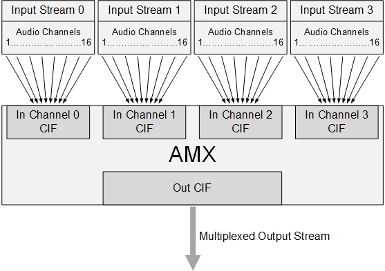
On code-name Parker devices the APE supports four AMXs and four ADXs. The device tree properties nvidia,num-amx and nvidia,num-adx indicate the total number of AMXs and ADXs to be registered. The nvidia,amx-slot-size and nvidia,adx-slot-size nodes indicate the slot map size of each AMX or ADX, which is related to the size of nvidia,amx-slot-map and nvidia,adx-slot-map.
As the following diagram shows, an AMX can multiplex data from up to four input streams, each containing up to sixteen 32-bit audio channels, into one output stream with up to sixteen 32-bit channels, forming a TDM signal. An ADX can demultiplex any signal multiplexed by an AMX.
A frame in the multiplexed output stream may be up to 64 bytes long, so it can hold up to 16 slots of 32 bits each. Thus an AMX can multiplex up to 16 of the input frame’s 64 channels into the output frame.
The AMX can map any byte in the input frame to any position in the output frame, though, so it is not limited to multiplexing complete 32-bit channels. For example, by mapping only the two high-order bytes of each input channel, it could multiplex up to 32 channels of 16 bits each into the output frame.
The mapping of input frames to output frames is controlled by a slot map which consists of up to 64 entries, one for each byte in the output frame. Each entry identifies one byte from the input frame and maps it to the corresponding byte in the output frame. That is, the first entry maps an input frame byte to output frame byte 0, the second entry maps an input frame byte to output frame byte 1, and so on.
The TDM_SLOT_MAP macro defines slot map entries in the device tree. It defines a slot map entry as a four-byte bit map:
#define TDM_SLOT_MAP(stream_id, nth_channel, nth_byte) \
((stream_id << 16) | (nth_channel << 8) | (nth_byte))
Where:
• stream_id is a stream ID number from 0 to 3
• nth_channel is a channel number from 1 to 16
• nth_byte is a byte number from 0 to 3
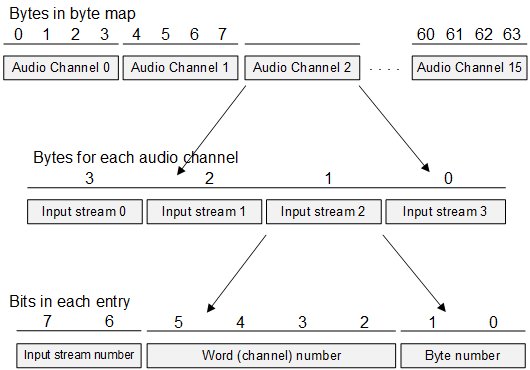
Audio Server converts the device tree’s slot map to a hardware slot map that the AMX and ADX can use. The next diagram shows the structure of the hardware slot map.
Each entry in the hardware slot map is one byte long, and contains:
• The number of an input stream, from 0 to 3 (two bits)
• The number of a channel in the input stream, from 0 to 15 (four bits)
• The number of a byte in the 32-bit value of that channel in that input stream, from 0 to 3 (2 bits)
For example, the following TDM_SLOT_MAP macro defines a slot map entry that maps byte 2 of input stream 3, channel 4:
TDM_SLOT_MAP(3,5,2)
It generates this entry in the device tree slot map:
0x00030502
When Audio Server converts the device tree slot map to the hardware slot map, it generates this entry:
0xD2 or 0b11010010
Note that the TDM_SLOT_MAP macro and the device tree slot map count the channel number from 1, but the hardware slot map counts it from 0. In the example, the TDM_SLOT_MAP macro and the device tree slot map reprsent channel 4 by the value 5, but the hardware slot map represents it by 4 (0b0100).
Here is an example of a definition of a complete device tree slot map:
nvidia,amx1-slot-map = <
TDM_SLOT_MAP(0, 0, 0)
TDM_SLOT_MAP(0, 0, 0)
TDM_SLOT_MAP(0, 1, 0)
TDM_SLOT_MAP(0, 1, 1)
TDM_SLOT_MAP(0, 0, 0)
TDM_SLOT_MAP(0, 0, 0)
TDM_SLOT_MAP(0, 2, 0)
TDM_SLOT_MAP(0, 2, 1)
TDM_SLOT_MAP(0, 0, 0)
TDM_SLOT_MAP(0, 0, 0)
TDM_SLOT_MAP(1, 1, 0)
TDM_SLOT_MAP(1, 1, 1)
TDM_SLOT_MAP(0, 0, 0)
TDM_SLOT_MAP(0, 0, 0)
TDM_SLOT_MAP(1, 2, 0)
TDM_SLOT_MAP(1, 2, 1)
TDM_SLOT_MAP(0, 0, 0)
TDM_SLOT_MAP(0, 0, 0)
TDM_SLOT_MAP(2, 1, 0)
TDM_SLOT_MAP(2, 1, 1)
TDM_SLOT_MAP(0, 0, 0)
TDM_SLOT_MAP(0, 0, 0)
TDM_SLOT_MAP(2, 2, 0)
TDM_SLOT_MAP(2, 2, 1)
TDM_SLOT_MAP(0, 0, 0)
TDM_SLOT_MAP(0, 0, 0)
TDM_SLOT_MAP(3, 1, 0)
TDM_SLOT_MAP(3, 1, 1)
TDM_SLOT_MAP(0, 0, 0)
TDM_SLOT_MAP(0, 0, 0)
TDM_SLOT_MAP(3, 2, 0)
TDM_SLOT_MAP(3, 2, 1)>;
nvidia,adx1-slot-map = <
TDM_SLOT_MAP(0, 0, 0)
TDM_SLOT_MAP(0, 0, 0)
TDM_SLOT_MAP(0, 1, 0)
TDM_SLOT_MAP(0, 1, 1)
TDM_SLOT_MAP(0, 0, 0)
TDM_SLOT_MAP(0, 0, 0)
TDM_SLOT_MAP(0, 2, 0)
TDM_SLOT_MAP(0, 2, 1)
TDM_SLOT_MAP(0, 0, 0)
TDM_SLOT_MAP(0, 0, 0)
TDM_SLOT_MAP(1, 1, 0)
TDM_SLOT_MAP(1, 1, 1)
TDM_SLOT_MAP(0, 0, 0)
TDM_SLOT_MAP(0, 0, 0)
TDM_SLOT_MAP(1, 2, 0)
TDM_SLOT_MAP(1, 2, 1)
TDM_SLOT_MAP(0, 0, 0)
TDM_SLOT_MAP(0, 0, 0)
TDM_SLOT_MAP(2, 1, 0)
TDM_SLOT_MAP(2, 1, 1)
TDM_SLOT_MAP(0, 0, 0)
TDM_SLOT_MAP(0, 0, 0)
TDM_SLOT_MAP(2, 2, 0)
TDM_SLOT_MAP(2, 2, 1)
TDM_SLOT_MAP(0, 0, 0)
TDM_SLOT_MAP(0, 0, 0)
TDM_SLOT_MAP(3, 1, 0)
TDM_SLOT_MAP(3, 1, 1)
TDM_SLOT_MAP(0, 0, 0)
TDM_SLOT_MAP(0, 0, 0)
TDM_SLOT_MAP(3, 2, 0)
TDM_SLOT_MAP(3, 2, 1)>;
The number of channels, input bits, and output bits for each module can also be configured separately for each of the input/outputs in that module. The format of a configuration entry is:
nvidia,<modulename><moduleid>-input-channels = <x y z . . .>;
nvidia,<modulename><moduleid>-output-channels = <x y z . . .>;
nvidia,<modulename><moduleid>-input-bits = <x y z . . .>;
nvidia,<modulename><moduleid>-output-bits = <x y z . . .>;
Where:
• <modulename> is the type of module, AMX or ADX.
• <moduleid> is the number of the module, 0 through 3.
• <x y z . . .> represents an array that specifies the number if input channels or input bits for the input streams, or the number of output channels or output bits for the output streams. In each case the array has one element per input/output stream.
For example:
nvidia,amx1-input-channels = <2 2 2 2>;
nvidia,amx1-output-channels = <8>;
nvidia,amx1-input-bits = <16 16 16 16>;
nvidia,amx1-output-bits = <32>;
Device Tree Based I2S Controller Configuration
You can use device tree configuration to change the clock source for an I2S controller. The node skeleton below shows a typical I2S controller node that defines a clock property:
i2s@<controller address> { /* Each element defines a clock handle: */
clocks = <i2s>, /* i2s controller */
<parent>, /* i2s controller parent */
<parent_sync>, /* parent as sync clk */
<selector>, /* i2s sync selector */
<sync_in>; /* i2s sync input */
};
By default, an I2S controller in master mode has a clock source configured for the pll_a_out clock. To change the I2S controller clock source, override the clocks property in the platform-specific DTS file. You only need to update the <parent> and <parent_sync> elements in skeleton shown above.
Possible values for <i2s> are:
TEGRA186_CLK_PLLA_OUT0
TEGRA186_CLK_SYNC_I2Sx
TEGRA186_CLK_CLKM
TEGRA186_CLK_PLLP_OUT0
Possible values for <parent_sync> are:
TEGRA186_CLK_I2S1_SYNC_INPUT
TEGRA186_CLK_I2S2_SYNC_INPUT
TEGRA186_CLK_I2S3_SYNC_INPUT
TEGRA186_CLK_I2S4_SYNC_INPUT
TEGRA186_CLK_I2S5_SYNC_INPUT
TEGRA186_CLK_I2S6_SYNC_INPUT
As an example, the default I2S1 configuration look like this:
i2s@2901000 {
clocks = <&tegra_car TEGRA186_CLK_I2S1>,
<&tegra_car TEGRA186_CLK_PLL_A_OUT>,
<&tegra_car TEGRA186_CLK_I2S1_SYNC_INPUT>,
<&tegra_car TEGRA186_CLK_SYNC_I2S1>,
<&tegra_car TEGRA186_CLK_I2S1_SYNC_INPUT>;
};
To derive the I2S1 controller clock from the I2S3 clock, we would define this node in the platform device tree:
i2s@2901000 {
clocks = <&tegra_car TEGRA186_CLK_I2S1>,
<&tegra_car TEGRA186_CLK_SYNC_I2S1>,
<&tegra_car TEGRA186_CLK_I2S3_SYNC_INPUT>,
<&tegra_car TEGRA186_CLK_SYNC_I2S1>,
<&tegra_car TEGRA186_CLK_I2S1_SYNC_INPUT>;
};
Storage Partition Configuration
The storage partitioning mechanism in virtualization is an extension provided to the native storage configuration via flashing .cfg files.
This section describes the additional parameters added to the flashing configuration file to support storage partitioning specific to virtualization, and the configuration required for partitioning storage media between multiple guest operating systems.
Configuration requires changes in the following locations:
• PCT
• Flashing CFG
• Guest OS Device Tree
The following example code is from DRIVE CX (P2382) Dual-Linux configuration.
PCT
The following code assigns IVC queues 66 and 67 to Linux and Linux_VM2 to exchange control message with VSC server, and IVC mempools 7 and 8 for Linux and Linux_VM2 to share read/write data with VSC server.
.ivc = {
...
.queues = {
…
/* VSC server */
[66] = { .peers = {GID_LINUX, GID_VSC_SERVER}, .nframes = 1, .frame_size = SZ_256K + SZ_512 },
[67] = { .peers = {GID_LINUX_VM2, GID_VSC_SERVER}, .nframes = 1, .frame_size = SZ_256K + SZ_512 },
...
},
.mempools = {
...
[7] = { .peers = {GID_LINUX_VM2, GID_VSC_SERVER}, .size = (SZ_1MB * 8), .align = (SZ_1MB * 2) },
[8] = { .peers = {GID_LINUX, GID_VM_SERVER}, .size = (SZ_1MB * 8), .align = 4096 },
...
},
See foundation/meta/pct/p2382-t186/linux-linux/platform_config.h for the complete PCT setting.
For more details on mempool & IVC configuration refer to PCT chapter.
Flashing CFG
Every virtualized partition must have the virtual_storage_ivc_ch attribute. The VSC server relies on this attribute to configure the layout of storage partitions.
The following table describes the virtual_storage_ivc_ch attribute bitfield.
Bits | Description |
31 | Specifies that this partition is controlled by storage server. |
24-30 | Specifies the guest ID of storage server. See the PCT for the guest ID. |
17-23 | Reserved for attributes. |
8-15 | Specifies the IVC mempool allocated to VSC communication and the guest to which this partition belongs. |
0-7 | Specifies the IVC queue allocated to VSC communication and the guest to which this partition belongs. |
The following example, extracted from foundation/meta/pct/p2382-t186/linux-linux/global_storage.cfg shows the usage of virtual_storage_ivc_ch. There are two virtualized partitions in the example.
[device]
type=sdmmc
instance=3
linux_name=/dev/block/3460000.sdhci
size=0xECE000000
[partition]
name=gos2
allocation_policy=sequential
filesystem_type=basic
size=0x768900000
partition_attribute=2
sub_cfg_file=linux2_storage.cfg
#VirtualStorageIVCChannel:
#[31] Is virtual storage
#[30:24] storage server id
#[23:16] attributes
#[8:15] mempool id
#[7: 0] ivc queue id
virtual_storage_ivc_ch=0x87000743
[partition]
name=gos1-mmc
allocation_policy=sequential
filesystem_type=basic
filesystem_type=ext4
size=0x765700000
partition_attribute=1
virtual_storage_ivc_ch=0x87000642
In the first virtualized partition, gos2:
• The physical start address is 0x0 because allocation_policy is sequential mode and the first partition is started from address 0x0.
• Partition Size is 0x768900000 bytes.
The mempool ID and IVC queue ID of virtual_storage_ivc_ch attribute specify that this partition belongs to the guest OS or vm server where they are defined in the platform configuration file foundation/meta/pct/p2382-t186/linux-linux/platform_config.h, as shown in the following example:
ivc queue:
[67] = { .peers = {GID_LINUX_VM2, GID_VSC_SERVER}, … }
ivc mempool:
[7] = { .peers = {GID_LINUX_VM2, GID_VSC_SERVER}, … }
According to the above IVC queue and mempool settings, the gos2 partition belongs to Linux VM2.
In the second virtualized partition, gos1-mmc:
• The partition gos1-mmc continues from partition gos2. The physical start address is 0x768900000.
• The total partition size is 0xECE000000 - 0x768900000 bytes.
The mempool ID and IVC queue ID of the virtual_storage_ivc_ch attribute specify which guest or VM server this partition belongs to. They are defined in the platform config file foundation/meta/pct/p2382-t186/linux-linux/platform_config.h as shown in the following example:
ivc queue:
[66] = { .peers = {GID_LINUX, GID_VSC_SERVER}, … }
ivc mempool:
[6] = { .peers = {GID_LINUX, GID_VSC_SERVER}, … }
According to the above IVC queue and mempool settings, the gos1-mmc belongs to Linux VM1.
Guest Device Tree
The tegra_hv_storage device node is added to the device tree of the guest OS to declare virtualized storage. In the example configuration described in the previous sections, gos2 belongs to Linux VM2 and gos1-mmc belongs to Linux VM1. The next step is to declare the partitions in the guest device tree.
The corresponding device nodes are reported to Linux VM1 in the device tree (Linux/hardware/nvidia/platform/t210/vcm/kernel-dts/tegra210-vcm31-p2382-0000-a00-00-vm1.dts) as shown in the following:
/* the virtual storage device node */
tegra_hv_storage {
compatible = "nvidia,tegra-hv-storage";
status = "okay";
instance = <0>;
ivc = <&tegra_hv 66>;
mempool = <6>;
};
The IVC and mempool attributess must match the corresponding setting the platform config file foundation/meta/pct/p2382-t186/linux-linux/platform_config.h. The IVC queue must be <66> and the mempool must be <6> for Linux VM1.
The corresponding device nodes are reported to Linux VM2 in the device tree (Linux/hardware/nvidia/platform/t210/vcm/kernel-dts/tegra210-vcm31-p2382-0000-a00-00-vm2.dts) as shown in the following example:
/* the virtual storage device node */
tegra_hv_storage {
compatible = "nvidia,tegra-hv-storage";
status = "okay";
instance = <0>;
ivc = <&tegra_hv 67>;
mempool = <7>;
};
The IVC and mempool attributes need to match the corresponding setting in the platform config file at foundation/meta/pct/p2382-t186/linux-linux/platform_config.h. The IVC queue must be <67> and the mempool must be <7> for Linux VM2.
Booting Guest OSes from Shared Storage
The VSC architecture allows multiple guests to boot from the same storage. The Partition Loader and OS Loader both have client drivers for communicating with the storage server.
The following is an example showing how to create boot stack partitions in the same storage for two guest OSes:
[device]
type=sdmmc
instance=3
linux_name=/dev/block/3460000.sdhci
size=0xECE000000
[partition]
name=gos1
allocation_policy=sequential
partition_attribut=1 //1 here refers to guest OS 1
e=size=0x810000000
sub_cfg_file=linux_storage.cfg
#VirtualStorageIVCChannel:
#[31] Is virtual storage
#[30:24] storage server id
#[23:16] attributes
# [16] Is read-only
#[8:15] mempool id
#[7: 0] ivc queue id
virtual_storage_ivc_ch=0x88000859 //ivc queue 0x59 and mempool 0x8
Partition gos1 is the boot partition of Guest1 (partition_attribut=1) and the guest storage configuration file is linux_storage.cfg.
In the following example, the configuration PL/OSL uses IVC queue 0x58 and IVC mempool 0x8 to to communicate with the VSC server to access this partition:
[partition]
name=gos3
allocation_policy=sequential
partition_attribute=3 //3 here refers to guest OS 3
size=0x6BE000000
sub_cfg_file=android_storage.cfg
virtual_storage_ivc_ch=0x8800095C //ivc queue 0x5C and mempool 0x9
Partition gos3 is the boot partition of Guest3 (partition_attribut=3) and the guest storage configuration file is android_storage.cfg. The configuration PL/OSL uses IVC queue 0x5C and IVC mempool 0x9 to communicate with the VSC server to access the partition.
Inter-VM Communication
Inter-VM Communication (IVC) is used to facilitate information exchange between two VMs over shared memory. The underlying shared memory format consists of a pair of circular FIFO buffers, one for each direction. To avoid the need for polling, a virtual interrupt implements signaling on special state transitions.
The pct_ivc_config structure’s mem_size, irq_start, irq_size, queues, and mempools members configure inter-VM communication.
System Trace
The System Trace feature records events which the System Profiler (SP) application can display in a timeline view. For HV events, the size of the buffer, as well as the type of events recorded, are configurable through the PCT.
The platform_conf structure’s log_size and trace_mask members configure the Hypervisor log buffer.
The guest_conf structure’s log_access member configures access to the Hypervisor log buffer.