Device Tree on Tegra
This SDK release supports device information provided with device tree data. A device tree is a tree-structure data format that represents information about the devices on a board.
Using device trees provides:
• Less “machine code” and “board” files
• A single unmodified kernel used for many platforms
If you are developing a product with SDK, device tree information is automatically included in your flashed image.
You must include device tree data in your flashed image when upgrading a product from an earlier SDK release. Future kernel versions are expected to support device trees and to deprecate board files.
Device Tree Format Overview
A device tree is a tree structure, containing kernel-level information about hardware, includes:
• Device characteristics
• Connections between devices (buses)
• Device configuration information
A device tree represents the hardware. The information in a device tree comes from sources such as hardware specifications and board schematics. Device tree data is represented in the following formats:
• Device Tree source files (*.dts and *.dtsi files)
• Flattened device tree (FDT) structures
The resolved DTS and DTSI files for a device are represented as an FDT structure.
• Binary, also referred to as device tree blobs (DTBs) (*.dtb files)
The device tree compiler (DTC) compiles the FDT structure into a DTB file. For information on the flattened device tree (FDT) format, see:
Device Tree Files in the BSP Framework
The Framework from NVIDIA includes device tree source files that describe the supported platforms.
There are Device Tree variations to support hardware differences between the multiple variants of each platform.
A hierarchy of DTSI files describes each platform:
|-- Base Platform DTS
|-- Platform Intermediate DTSI
|-- Platform Common DTSI
|-- SoC DTSI
The SDK supplies the DTS files in the following directories:
<top>/hardware/nvidia/soc/t186/ <top>/hardware/nvidia/platform/t186
• tegra186-vcm31_<p3407c01-t186a|p2379c01-t186a>-base-*.dtsi
Files named with this syntax contain chip-specific nodes common for boards that have the Tegra version in question.
• tegra186186-vcm31t186186-common.dtsi
Files named with this syntax contain a Device Tree for the vcm31 platform with the specified Tegra version.
These DTS and DTSI files associate with each other using include statements, to allow the reuse of pre-existing Device Tree nodes. A board-00 DTS file includes the relevant board DTSI file, which includes the relevant chip-specific DTSI file, which in turn includes the relevant SoC DTSI file.
Example: Platform DTS
The VCM31T186 platform is represented by tegra186-vcm31-p2382-010-a01-00-base.dtsi, shown here, the board common DTSI tegra186-vcm31-p2382-010-a01-00-common.dts:
#include "tegra186-vcm31-p2382-010-a01-00-base.dtsi"
/ {
nvidia,dtsfilename = __FILE__;
nvidia,boardids = "p2382:0010:A01";
nvidia,proc-boardid = "p2382:0010:A01";
};
Example: Platform Intermediate DTSI
The tegra186-vcm31-p2382-common.dtsi file is included in the tegra186-vcm31-p2382-010-a01-00-base.dtsi file:
/* This file has the board specific information */
#include "vcm-platforms/tegra186-vcm31-p2382-common.dtsi"
#include "vcm-platforms/tegra186-vcm31-p2382-disp.dtsi"
#include "vcm-prod/tegra186-priv-vcm31-p2382-010-a01-00-prod.dtsi"
#include "vcm-plugin-manager/tegra186-vcm31-p2382-010-a01-00-plugin-manager.dtsi"
/ {
memory@80000000 {
device_type = "memory";
reg = <0x0 0x80000000 0x0 0x70000000>;
};
firmware {
android {
compatible = "android,firmware";
hardware = "p2382_t186";
};
};
Example: Platform Common DTSI
The tegra186-vcm31.dtsi file is included in the tegra186-vcm31-p2382-common.dtsi file.
#include <dt-bindings/types.h>
#include <dt-bindings/input/input.h>
#include <dt-bindings/gpio/tmpm32x-gpio.h>
#include <dt-bindings/input/atmel_mxt_ts.h>
/dts-v1/;
/memreserve/ 0x80000000 0x00010000;
#include "tegra186-vcm31.dtsi"
#include "tegra186-vcm31-power-tree-p2382-010-a01-00.dtsi"
#define EXTCON_NONE 0
#define EXTCON_USB 1
#define EXTCON_USB_Host 2
/ {
model = "p2382_t186";
compatible = "nvidia,p2382_t186", "nvidia,tegra186";
nvidia,dtbbuildtime = __DATE__, __TIME__;
#address-cells = <2>;
#size-cells = <2>;
pmc@c360000 {
Example: Chip DTSI
The tegra186-vcm31.dtsi file is the common DT file for vcm31t186.
#include "tegra186-soc/tegra186-soc-vcm.dtsi"
#include <t18x-common-platforms/tegra186-platforms-eqos.dtsi>
#include "tegra186-vcm31-thermal.dtsi"
#include "tegra186-soc/tegra186-soc-audio.dtsi"
#include <t18x-common-platforms/tegra186-platforms-simple-bus.dtsi>
#include "tegra186-vcm31-camera-sce.dtsi"
#include <dt-bindings/sound/tegra-asoc-alt.h>
/ {
serial@3100000 {
The tegra186-soc-vcm.dtsi file includes the common DT file for t186 SOC.
#include "tegra186-soc/tegra186-cpus-2D4A.dtsi"
#include "tegra186-soc/tegra186-soc-base.dtsi"
#include "tegra186-soc/tegra186-soc-prod.dtsi"
#include "tegra186-soc/tegra186-soc-audio.dtsi"
/ {
aliases {
Viewing Pinmux Settings in the DTS
Quickboot configures the pinmux; the kernel does not configure them.
The device tree entries for pinmux are visible in the following procfs location. It contains the different states defined for dynamic pinmux configuration.
/proc/device-tree/pinmux@70000868
For guidance on viewing the values of the pinmux and drive strength registers, see
Sysfs and Profs Entries in
Utilities.
Kernel DTS Compilation and Flashing
The framework build system compiles the kernel DTS and DTSI files for your platform into DTB data included in the flash image. Along with the kernel, DTB files are automatically built.
The boot loader uses the libfdt library to manage DTB data. With this library, Quickboot performs the following tasks:
1. Reads the DTB from the kernel-dtb partition, if it exists.
2. Modifies the DTB to add device tree nodes that are specific to the platform.
3. Passes the augmented DTB to the kernel, if Quickboot initially read the DTB from the kernel-dtb partition.
To flash a custom DTB file
• Flash the file with the bootburn -u option, and provide the path to your customized DTB file.
The default is tegra186-vcm31-<p3407|p2379>-010-a01-00-base.dtb.
Configuring Device Tree Support
By default, the board configuration files enable device tree support for a DTB partition Tegra device. The TARGET_KERNEL_DT_NAME configuration contains the prefix for the DTB/DTSI files for your platform.
Device Tree Data Format
The device tree data format is a data format that represents information for the devices on a board and has these characteristics:
• A tree structure of nodes and properties
• A single root node “/”
• Child nodes with properties
• Key-value pairs represent properties
• Keys used as property identifiers
• Values are empty or byte streams
• Data types of streams:
• Strings: "Value"
• List of strings: "Value_1", "Value_1"
• Binary data: [0x1 0x2 0x3]
• Cells: <1 0x2 0x3>
Device Tree is part of the OpenFirmware industry standard (IEEE 1275).
For more information, see:
SW-EDID
SW-EDID is a mechanism to provide EDID as a blob in a DTB. The driver reads the EDID data from the device tree instead of from the panel/monitor. SW-EDID is useful in the following cases:
• DDC channel of HDMI is not connected and a method is required to provide mode information to the driver. Instead of hardcoding the board file, the EDID blob is supplied in the DTB so that the driver can read it at runtime.
• Debugging or experimental purposes when there is a need to override the EDID.
Drivers
SW-EDID supports HDMI, DP, and LVDS drivers.
Generating EDID Blob
nv_edidgenerate is a command line tool to generate a single mode 128-byte EDID blob.
For SDK builds, the path of the tool is:
<
top>/utils/nv_edidgenerate
To view the EDID-generate tool usage information
• Run nv_edidgenerate without any arguments. The following information is displayed:
./nv_edidgenerate pclk(10khz),hactive,hblank,vactive,vblank,hoffset,hpulse,voffset,vpulse
ARGUMENTS:
pclk : Pixel clock in 10khz
hactive : Horizontal Resoulution in pixels
hblank : Horizontal blanking in pixels (back porch + sync width + front porch)
vactive : Vertical Resoulution in lines
vblank : Vertical blanking in lines (back porch + sync width + front porch)
hoffset : Horizontal front porch in pixels
hpulse : Horizontal sync pulse width in pixels
voffset : Vertical front porch in lines
vpulse : Vertical sync pulse width in lines
To generate an EDID blob
• Run nv_edidgenerate, providing the values of your display panel as arguments. For example, to generate an EDID blob for a 1920 x 1080 display, execute:
./nv_edidgenerate 14850,1920,280,1080,45,88,44,4,5
Where:
• 14850 is the pixel clock in increments of 10 kHz.
• 1920 is the horizontal resolution in pixels.
• ...
• 5 is the vertical sync pulse width in lines.
A successful run displays an output similar to the following:
#####################################################
EDID BYTES:
0x 00 01 02 03 04 05 06 07 08 09 0A 0B 0C 0D 0E 0F
------------------------------------------------
00 | 00 FF FF FF FF FF FF 00 04 21 00 00 00 00 00 00
10 | 01 00 01 03 00 00 00 00 00 00 00 00 00 00 00 00
20 | 00 00 00 00 00 00 01 01 01 01 01 01 01 01 01 01
30 | 01 01 01 01 01 01 02 3A 80 18 71 38 2D 40 58 2C
40 | 45 00 00 00 00 00 00 00 00 00 00 10 00 00 00 00
50 | 00 00 00 00 00 00 00 00 00 00 00 00 00 10 00 00
60 | 00 00 00 00 00 00 00 00 00 00 00 00 00 00 00 10
70 | 00 00 00 00 00 00 00 00 00 00 00 00 00 00 00 E9
#####################################################
To add an EDID blob to the DT node for an HDMI driver
The following example adds an EDID blob for an HDMI display driver. You can add DP and other types of displays in a similar way.
1. Locate and edit the DTS/DTSI file for your platform, for example:
<kernel>/arch/arm64/boot/dts/tegra186-platforms/tegra186-vcm31-<p3407|p2379>.dtsi
<kernel>/arch/arm/boot/dts/tegra-platforms/tegra186-platforms/tegra186-vcm31-<p3407|p2379>-disp.dtsi
<kernel>/arch/arm/boot/dts/tegra186-platforms/tegra186-vcm31-<p3407|p2379>-hdmi.dtsi
-Or-
Use the top level .dts file to override settings in the included .dtsi files:
<kernel>/arch/arm/boot/dts/tegra186-<p3407|p2379>.dts
2. Add the NVIDIA EDID attribute to one of the following Device Tree properties:
/host1x/hdmi/hdmi-display/nvidia,edid
/host1x/sor/hdmi-display/nvidia,edid
/host1x/sor1/hdmi-display/nvidia,edid
For example:
host1x {
hdmi {
status = "okay";
nvidia,ddc-i2c-bus = <&hdmi_ddc>;
nvidia,hpd-gpio = <&gpio TEGRA_GPIO(N, 7) 1>; /* PN7 */
hdmi-display {
nvidia,edid = [00 FF FF FF FF FF FF 00 04 21 00 00 00 00 00 00
01 00 01 03 00 00 00 00 00 00 00 00 00 00 00 00
00 00 00 00 00 00 01 01 01 01 01 01 01 01 01 01
01 01 01 01 01 01 02 3A 80 18 71 38 2D 40 58 2C
45 00 00 00 00 00 00 00 00 00 00 10 00 00 00 00
00 00 00 00 00 00 00 00 00 00 00 00 00 10 00 00
00 00 00 00 00 00 00 00 00 00 00 00 00 00 00 10
00 00 00 00 00 00 00 00 00 00 00 00 00 00 00 E9];
};
};
};
USB/PCIe/SATA Device Tree Configuration
This section describes how device tree is configured for USB/PCIe/SATA modules in Tegra Parker VCM based systems (DRIVE CX 2 (P2382) SKU10 is used as example) in order to aid customization of device tree on customer platforms that use Tegra Parker VCM.
Relevant device tree entries for the reference platform (DRIVE CX 2 (P2382) SKU10) can be found in these files:
<top>/drive-oss-src/kernel-t18x/arch/arm64/boot/dts/tegra186-platforms/tegra186-vcm31-p2382-common.dtsi
<top>/drive-oss-src/kernel-t18x/arch/arm64/boot/dts/tegra186-soc/tegra186-soc-base.dtsi
The relevant device tree entries can be split into four distinct parts: UPHY, USB, PCIe and SATA.
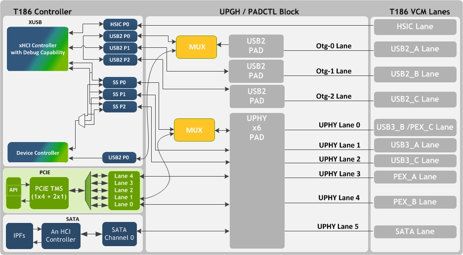
UPHY
In Tegra Parker, VCM, USB, PCIe and SATA lanes are routed through UPHY hardware block. The term “lane” in uphy-lane-x refers to dual differential signal pairs needed to handle differential Rx and Tx data paths (Rx-,Rx+,Tx-,Tx+) used by USB Super speed/PCIe/SATA whereas with otg-x, it indicates a single differential signal pair which is used by USB High Speed. In order to reduce Tegra Parker VCM pin count, there are only six lanes available in UPHY module. For example, PCIe lane 1 and USB Super Speed lane 0 are multiplexed in UPHY block.
The following illustration depicts how lanes are shared between USB/PCIe/SATA in Tegra Parker VCM.
Note 1: | The PCIe controller, in Tegra Parker VCM, supports three root ports with single lane configuration. The following shows which PCIe lanes, as depicted within PCIe controller block, are used by the root ports: • PCIe Root Port 0 > PCIe Lane 0 • PCIe Root Port 2 > PCIe Lane 1 • PCIe Root Port 1 > PCIe Lane 4 |
Note 2: | In the above diagram, USB2 PX indicates High Speed Port Number X. Likewise, SS PY indicates Super Speed Port Number Y. These can be used independent of each other to provide High Speed only or Super Speed only connections on-board. If a Super Speed connector is provided, a Super Speed port must be combined with a High Speed port. Refer to the VCM Design Guide or contact your NVIDIA Customer Engineer for details. |
The UPHY/PADCTL driver in BPMP firmware manages the UPHY/PADCTL block and thus controls which functions (between USB, PCIe, and SATA) get to use the six lanes available with UPHY. BPMP Device Tree documentation is available in Foundation SDK Development Guide.
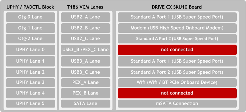
In DRIVE CX 2 (P2382) SKU10 platform the following is the actual USB/PCIe/SATA usage.
The following are the UPHY device tree entries particular to DRIVE CX 2 (P2382) SKU10:
pinctrl@3520000 {
status = "okay";
pinctrl-0 = <&p2382_padctl_default>;
pinctrl-names = "default";
p2382_padctl_default: pinmux {
usb2-std-A-port1 {
nvidia,lanes = "otg-0";
nvidia,function = "xusb";
nvidia,port-cap = <TEGRA_PADCTL_PORT_OTG_CAP>;
};
usb3-std-A-port1 {
nvidia,lanes = "usb3-1";
nvidia,port-cap = <TEGRA_PADCTL_PORT_OTG_CAP>;
};
usb2-modem {
nvidia,lanes = "otg-1";
nvidia,function = "xusb";
nvidia,port-cap = <TEGRA_PADCTL_PORT_HOST_ONLY>;
};
usb2-std-A-port2 {
nvidia,lanes = "otg-2";
nvidia,function = "xusb";
nvidia,port-cap = <TEGRA_PADCTL_PORT_HOST_ONLY>;
};
usb3-std-A-port2 {
nvidia,lanes = "usb3-2";
nvidia,port-cap = <TEGRA_PADCTL_PORT_HOST_ONLY>;
};
};
};
• std-A-port1 is a Super Speed OTG port that uses otg-0 (usb2-std-A-port1 node) lane for supporting high speed and uphy-lane-1 (usb3-std-A-port1 node) for supporting super speed. The NVIDIA function property is setup in these nodes to indicate these port usages.
• TEGRA_PADCTL_PORT_OTG_CAP (nvidia,port-cap property) indicates that the port is an OTG port. If OTG capability is not needed, and only Host mode or device mode is needed, TEGRA_PADCTL_PORT_HOST_ONLY or TEGRA_PADCTL_PORT_DEVICE_ONLY can be selected instead.
Note: | Only otg-0 high speed lane can be used with TEGRA_PADCTL_PORT_OTG_CAP. |
• Modem (usb2-modem) is a USB high speed only connection to an onboard USB device that uses otg-1 lane. Since it is a host only connection, the port-cap property indicates TEGRA_PADCTL_PORT_HOST_ONLY.
• std-A-port2 is a Super Speed USB connector that uses otg-2 and uphy-lane-2 lanes and operates in host mode.
The onboard Wi-Fi device that is connected to Tegra Parker using PCIe connection is enabled by selecting the PCIe function for uphy-lane-3. Similarly, uphy-lane-5 is configured for SATA connection.
USB
The following are the device tree settings for USB host controller driver particular to DRIVE CX 2 (P2382) SKU10:
xhci@3530000 {
status = "okay";
nvidia,pmc-usb-wakes-disabled;
extcon-cables = <&vbus_id_extcon 1>;
extcon-cable-names = "id";
#extcon-cells = <1>;
phys = <&tegra_xusb_padctl TEGRA_PADCTL_PHY_UTMI_P(0)>,
<&tegra_xusb_padctl TEGRA_PADCTL_PHY_UTMI_P(1)>,
<&tegra_xusb_padctl TEGRA_PADCTL_PHY_UTMI_P(2)>,
<&tegra_xusb_padctl TEGRA_PADCTL_PHY_USB3_P(1)>,
<&tegra_xusb_padctl TEGRA_PADCTL_PHY_USB3_P(2)>,
<&tegra_ext_cdp 0>,
<&tegra_ext_cdp 2>;
phy-names = "utmi-0", "utmi-1", "utmi-2", "usb3-1", "usb3-2",
"cdp-0", "cdp-2";
};
The 3 USB connections (2 Super Speed connectors and 1 High Speed onboard device) on DRIVE CX 2 (P2382) SKU10 use these ports from XUSB controller: USB2 P0, USB2 P1, USB2 P2, SS P1 and SS P2. These are enabled using phys and phy-names properties. There is no need to distinguish between the OTG ports (USB2 P0, SS-P1) and the non-OTG ports.
The platform also uses a GPIO to provide ID pin input for the OTG port (indicated by extcon-cables and extcon-cable-names properties). The following device tree entry provides support for this:
external-connection {
vbus_id_extcon: extcon@1 {
compatible = "extcon-gpio-states";
reg = <0x1>;
extcon-gpio,name = "VBUS";
/*
* Array of gstate(input), cstate(output) pairs. Each
* pair shows how to map GPIO signal values into cable
* states as defined by the consumer in question.
* Here:
*
* gstate[x].bit0 -> ID signal input
*
* cstate[x].bit0 -> VBUS cable
* cstate[x].bit1 -> nID cable
*
* Since we don't support VBUS sensing, in gadget mode
* (cstate[x].bit1 == 0), set cstate[x].bit0 to 1.
*/
extcon-gpio,cable-states = <0x1 0x1
0x0 0x2>;
gpios = <&spmic 0 0>;
extcon-gpio,out-cable-name-strings = "USB", "USB-Host";
extcon-gpio,out-cable-names = <EXTCON_USB EXTCON_USB_Host EXTCON_NONE>;
#extcon-cells = <1>;
};
};
Note: | Based on the comments given for the “extcon” configuration above, it can be seen that the VBUS/ID state as seen by drivers in software is derived based on the PMIC GPIO0 signal. If a different GPIO is used in the platform, the gpios property should be changed to reflect that. Since the extcon-gpio-states driver needs at least one GPIO as input, the gpios property can refer to PMIC GPIO0 if there is no GPIO on the board that can be used for determining the state of VBUS/ID input to software (assuming PMIC GPIO0 is not used for any other purpose). |
If a platform needs VBUS/ID state to be hard-coded (for example when there is no physical GPIO in the platform indicating ID pin input), extcon-gpio,cable-states can be altered to achieve that.
For example, if the OTG port must be in host mode by default during system boot-up, use the value <0x1 0x2 0x0 0x2>. Similarly, if the OTG port must be in device mode by default, use <0x1 0x1 0x0 0x1>.
The OTG port state can then be changed between host mode and device modes post-boot by using the mechanism documented in the USB Role-Switch Architecture appendix.
When std-A-port1 port is acting in device mode, gadget controller support is needed. The following device-tree entry supports it:
xudc@3550000 {
status = "okay";
extcon-cables = <&vbus_id_extcon 0>;
extcon-cable-names = "vbus";
#extcon-cells = <1>;
phys = <&padctl_uphy TEGRA_PADCTL_UPHY_UTMI_P(0)>,
<&padctl_uphy TEGRA_PADCTL_UPHY_USB3_P(1)>;
phy-names = "usb2", "usb3";
};
The gadget controller driver uses USB2 P0 and SS P1 USB ports.
Note: | The same ports are used by the host controller driver. Based on the ID pin state, the host controller and gadget controller driver share the physical ports by requesting UPHY driver. |
PCIe
PCIe driver uses the following device tree node for determining the configuration that is needed for DRIVE CX 2 (P2382) SKU10:
pcie-controller@10003000 {
/*
* Even though the board is using PCIe root ports in 0_0_1
* configuration, we have to provide 1_1_1 to the driver since
* it does not consider 0 to be a valid lane configuration for
* any of the ports.
*/
status = "okay";
pci@1,0 {
status = "disabled";
nvidia,num-lanes = <1>;
};
pci@2,0 {
nvidia,num-lanes = <1>;
status = "okay";
};
pci@3,0 {
nvidia,num-lanes = <1>;
};
};
The property nvidia,lane-map is always to be configured with 0x111 for Tegra parker VCM based designs. Here PCIe root ports 0 (pci@1,0) and 1 (pci@2,0) are enabled in single lane configuration. All the root-ports of Tegra parker VCM based designs have to be configured in single lane mode when enabled (set by default for root ports 1 and 2 in tegra186-soc-base.dtsi).
SATA
There is no DRIVE CX 2 (P2382) SKU10 specific configuration needed for the SATA driver.