Time Synchronization (P2379)
The NVIDIA DRIVE™ PX 2 has multiple time domains. Outside the DRIVE PX 2 are additional time domains.
When software processes data that has been timestamped in more than one time-domain, it must be able to synchronize the timestamps, that is, convert them all to a common time domain. Due to the different crystals and oscillators used by different system components, synchronization requires more than a simple mathematical transformation. In this topic, NVIDIA recommends best practices for choosing a common time domain and minimizing timestamp jitter.
Overview of Timestamps
In a complex system like NVIDIA DRIVE PX 2, data is often timestamped in one time domain then is transmitted to, and consumed in, another. The system must be designed to provide the consuming software the most accurate timestamp possible, and to transform it correctly to an appropriate time domain.
Timestamps are generally most accurate if they are applied as close as possible to the source of the data. This minimizes delays in data transmission and delays caused by processing before the timestamp is applied.
It is better to apply timestamps in hardware than in software, as hardware timestamps generally are applied with less processing delay, making them more accurate. Hardware timestamping also avoids jitter due to variations in software scheduling.
Timestamping close to the data source adds complexity, though, when it causes timestamps to be applied in a different time domain than the one in which the data will be received and consumed. In some cases, the receiver does not have access to information about the source time domain, making it impossible to translate timestamps accurately. In such cases the receiver must use a timestamp that is applied farther from the source.
Even where software cannot use a timestamp applied close to the data source, it is important to maximize timestamp accuracy. The best place to apply timestamps in such a case is in the data receiver’s hardware. For example, the receiver of Ethernet packets may apply a hardware PTP timestamp to the packets. If the delay between data generation and timestamping (including packetization) is constant or nearly constant, the receiver can compensate for it when applying the timestamp. Such compensation is not always possible, though.
When hardware timestamping in the receiver is also impractical, the remaining approach is software timestamping in the receiver. It is desirable to apply timestamp as close to receive event as possible, and with the least possible overhead and variability. The best place to apply a software timestamp is often an interrupt service routine (ISR). Any software timestamping process increases jitter, though, due to variations in scheduling.
Aurix/Tegra A/Tegra B Synchronization
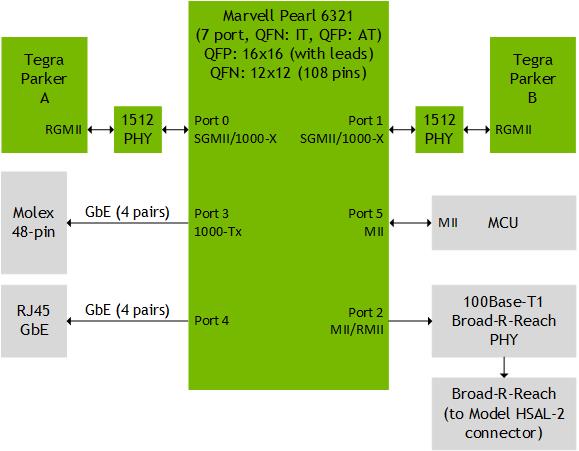
Below is a simplified diagram of NVIDIA DRIVE PX 2 Ethernet connections.
To get datasheets for the components shown in the diagram, use these links:
• Marvell Pearl 6321:TBD
• 1512 PHY: TBD
• Infineon AURIX TC29x: TBD
The Marvell switch, AURIX, and NVIDIA® Tegra® all support Precision Time Protocol (PTP, IEEE 1588), with hardware support for time synchronization. PTP enables a decentralized system to synchronize clocks that are distributed over Ethernet networks to an accuracy of less than 1 microsecond.
In NVIDIA DRIVE PX 2, AURIX is the PTP clock master. The Marvell switch and hardware time synchronization support provide more precise synchronization than software-only PTP could provide.
All data shared between the Marvell switch, AURIX, and Tegra processors must have timestamps in the PTP time domain. Therefore, any timestamped data that is shared between processors must have its timestamp transformed to the PTP time domain before the originating processor transmits it.
Tegra A CAN/Tegra B CAN
Tegra processors support hardware timestamping of received CAN packets. The received CAN packet hardware timestamps are rebased to PTP time base. The CAN hardware timestamp base is updated periodically to match PTP time.
Notes: | The PTP timestamp applied to an incoming CAN packet represents the time when the CAN packet was received. It is better to use a timestamp applied at the data source. PTP timestamp base is used if PTP is enabled. If not, ktime_get_real() is used as timestamp base. |
AURIX Timestamping
NVIDIA desire is to AURIX timestamping move to PTP. This is still under investigation. The thought being any data provided to Tegra(s) from AURIX is immediately usable and AURIX can provide transformation with the maximum accuracy.
Tegra A/Tegra B Ethernet Timestamping
It is possible for NVIDIA to timestamp Ethernet packets with PTP hardware timestamp. NVIDIA is investigating this solution.
Tegra A/Tegra B CSI Camera Frame Timestamping
NVIDIA is looking at moving current timestamping done in frame capture ISR to PTP (get_ptp_hwtime()).
Implementing a PTP Hardware-Based Timestamp
In this use case, a timestamp is generated by hardware whose timer base can be overridden with PTP time.
An example implementation is available at:
<top>/include/linux/platform/tegra/ptp-notifier.h.
Note: | PTP timestamp base is be used if PTP is enabled. If not, ktime_get_real() is used as timestamp base. |
Implementing PTP SW Based Timestamp
In this usecase, software uses the current PTP time to set the timestamp. The routine get_ptp_hwtime() returns the 64‑bit PTP time as a u64 value.
More details are provided at:
include/linux/platform/tegra/ptp-notifier.h.
Note: | PTP timestamp base is used if PTP is enabled. If not, ktime_get_real() is used as timestamp base. |