Understanding NvMedia
The NvMedia Video domain handles the following processes:
• Video Surface data (hardware buffer). For example, YUV, RGB, progressive, and interlaced.
• Hardware synchronization, as necessary.
Video Decode
NvMedia video decode is a frame-level API. NvMedia implementations:
• Accept frame data from the bitstream.
• Perform all required processing of those frames.
For example, VLD decoding, IDCT, motion compensation, and in-loop deblocking.
The client application is responsible for:
• Extracting the slices from the bitstream.
For example, parsing/demultiplexing container formats, and scanning the data to determine frame start positions and frame sizes.
• Parsing various bitstream headers and structures.
For example, the sequence header, sequence parameter set, picture parameter set, and entry point structures. Various fields from the parsed header structures must be provided to NvMedia alongside the slice bitstream in a “picture information“ structure.
• Feeding in the buffer containing bitstream per frame to decoder.
• Managing the surface.
For example, H.264 DPB processing, and display re-ordering.
Supported Video Media Formats
The supported video media formats are as follows.
Media Format | Description |
MPEG-1 | Includes all slices beginning with start codes 0x00000101 through 0x000001AF. The slice start code must be included for all slices. |
H.264 | Supports bit streams with Baseline / Main / High profile up to 5.1 level. If desired: • The slice start code prefix may be included in a separate bitstream buffer array entry to the actual slice data extracted from the bitstream. • Multiple bitstream buffer array entries (e.g., one per slice) may point at the same physical data storage for the slice start code prefix. |
H.265 | Supports bit streams with Main profile up to 5.1 high tier. |
VC-1 Simple and Main Profile | Consists of a single slice per picture. Does not use start codes to delimit pictures. The container format must indicate where each picture begins and ends. Slice start codes must not be included in the data passed to NvMedia, pass in the exact data from the bitstream. Header information, contained in the bitstream, must be parsed by the application and passed to NvMedia using the “picture information” data structure. This header information explicitly must not be included in the bitstream data passed to NvMedia for this encoding format. |
Vc-1 Advanced Profile | Includes all slices beginning with start codes 0x0000010D (frame), 0x0000010C (field) or 0x0000010B (slice). The slice start code must be included in all cases. Some VC-1 advanced profile streams do not contain slice start codes; again, the container format must indicate where picture data begins and ends. In this case, pictures are assumed to be progressive and to contain a single slice. It is highly recommended that applications detect this condition, and add the missing start codes to the bitstream passed to NvMedia. However, NvMedia implementations must allow bitstreams with missing start codes, and act as if a 0x0000010D (frame) start code had been present. • Pictures containing multiple slices, or interlace streams, must contain a complete set of slice start codes in the original bitstream; without them, it is not possible to correctly parse and decode the stream. The bitstream passed to NvMedia should contain all original emulation prevention bytes present in the original bitstream; do not remove these from the bitstream. |
MPEG-4 Part 2 | Includes all slices beginning with start codes 0x000001B6. The slice start code must be included for all slices. |
VP8 | Includes VP8 bitstream with level 0-4. |
VP9 | Includes all VP9 bitstream with profile 0. |
Surfaces are not suitable for CPU access.
Using the Software Video Decoders
NvMedia provides two functions to support software video decoders.
• The decoder obtains a mapped YUV video surface by calling the NvMediaVideoSurfaceLock function.
During the call, NvMedia waits while the surface is being used by the internal engines. Consequently, this is a blocking call. Once the function returns, the surface is used by the software decoder. The returned parameters are the mapped memory YUV pointers and the associated pitches.
It also returns the width and height in terms of luma pixels.
• When the decoder finishes filling up the surfaces, it calls the NvMediaVideoSurfaceUnlock function.
This tells NvMedia that the surface can be used for the internal engines.
On certain Tegra platforms, the mapping returns a NULL pointer indicating that the surface is not CPU accessible.
Video Encode
NvMedia Video Encode for NVENC supports the following features:
• Accepts YUV/RGB frames as input.
• Encodes content for Internet, common SD and HD formats up to dual streams of 1920 x 1080.
• Supports H.264 Baseline, Main and High profiles.
• Provides frame-only encoding.
• For I-frame or I/P-frame encoding, the low-level hardware driver (TVMR) code handles the picture type according to the Group of Pictures (GOP) and IDR period.
• For I/B/P encoding, the picture re-ordering is handled in application code by assigning the picture type and sending it to the low-level hardware driver (TVMR) for encoding.
• Supports all intra-macroblock types (16 x 16, 8 x 8, 4 x 4, PCM) and prediction types.
• Supports inter-macroblock partition sizes from 16 x 16, 16 x 8, 8 x 16 down to 8 x 8, and skip and direct B-modes.
• Supports disable, temporal, or spatial direct mode for:
• B-picture
• One reference picture for P-picture
• Two reference pictures for B-picture
• Supports multiple rate-control modes including:
• Constant QP
• Constant Bit Rate (CBR) single-pass
• Variable Bit Rate (VBR)
• VBR with minimum QP
• Supports dynamic slice mode based on byte size and static multiple slices in the frame.
• Supports intra-refresh mode with refresh period, and instant refresh P-picture.
• Supports adaptive 8x8 transform mode.
• Supports VUI and SEI insertion.
• Supports CAVLC and CABAC.
• Supports rotation/mirroring mode.
• Supports dynamic configure changes at the frame level:
• SPS PPS output on next frame
• Constrained frame encode
• Instant intra refresh P picture
• New SEI packet insertion
• GOP length and IDR period update
• Rate control mode change
For H.265 encoding, the encoder has the following features:
• Accepts YUV/RGB frames as input.
• Encoding common SD and HD resolutions up to dual streams of 3840 x 2160.
• Supports H.265 Main profiles with level up to 6.0.
• Supports Frame only encoding.
• For I only or I/P encoding, the low-level hardware driver (TVMR) code handles the picture type according to the Gop, Idr period. B pictures are not supported.
• Supports ll intra CU types (32 x 32, 16 x 16, 8 x 8, 4 x 4, PCM) and prediction types.
• Inter CU partition sizes from 32x32 to 8x8, with partition mode of PART_2Nx2N, PART_2NxN, PART_Nx2N, PART_2NxnU, PART_2NxnD, PART_nLx2N PART_nRx2N plus skip.
• 1 reference picture for P picture.
• Multiple rate-control modes—constant QP, CBR (single-pass), VBR, VBR with min QP. Other modes such as multi-pass CBR could be supported in future software releases.
• Dynamic slice mode based on byte size and static multiple slices in the frame.
• Intra refresh mode with refresh period, and instant refresh P picture.
• VUI and SEI insertion.
• CABAC only.
• Dynamic configure change at frame level:
• SPS PPS output on next frame
• Constrained frame encode
• Instant intra refresh P picture
• New SEI packet insertion
• Gop length and IDR period update
• Rate control mode change
Video Mixer
The video mixer supports scaling, cropping, transformation, and de-interlacing of a Video Surface and storing the result into an output Video Surface. The input and the output surfaces can be YUV or RGB types. If the output type differs from the input type the mixer performs color space conversion.
The following table describes the features that are supported depending of the input and output surface types.
Conversion Type | Composition | Alpha Blend | Scaling | Cropping | ProcAmp | De-Interlace |
YUV to RGB | Yes | Yes | Yes | Yes | Yes | Yes |
YUV to YUV | No | No | Yes | Yes | No | Yes |
RGB to RGB | No | No | Yes | Yes | No | No |
RGB to YUV | No | No | Yes | Yes | No | No |
Composition
The NvMediaVideoMixerRenderSurface function supports two layers of images composited in the following order:
• Background (optional)
• Video
The presence of the background layer is determined at the video mixer creation phase, through the following feature:
NVMEDIA_VMP_FEATURE_BACKGROUND_PRESENT
The background layer supports a single color.
Alpha blending
The VideoMixerRenderSurfaceWithAlpha function supports an input video surface and input alpha surface and produces an alpha blended output. Regular and pre-multiplied type alpha blending are supported. This function does not support background layer composition.
ProcAmp (Processing Amplifier)
The following ProcAmp functions are supported:
• Brightness (Luminance)
• Contrast (Gain)
• Saturation (Amplitude)
• Hue (Phase)
• Noise reduction
• Sharpening
• Inverse Telecine
Layer Usage
Background Layer
The background layer is an optional layer.
• It can display a solid color.
• For color mode, the backgroundColor determines the color.
Video Layer
Video layer is the main video playback layer. NvMediaVideoDesc is used to describe this layer.
• pictureStructure, next, current, previous and previous2 are describing the type and video surfaces to be used.
• srcRect determines which portion of the source video surface is used.
• This rectangle from the source gets zoomed into dstRect.
• dstRect determines the rectangle where the video is going to be rendered.
• The position of this rectangle is relative to the destination surface.
• The destination surface size is determined at NvMediaVideoMixer creation.
Each NvMediaVideoSurface must contain an entire frame's-worth of data, irrespective of whether an interlaced of progressive sequence is being decoded.
Depending on the exact encoding structure of the compressed video stream, the application may need to call NvMediaVideoDecoderRenderEx twice to fill a single NvMediaVideoSurface.
When the stream contains an encoded progressive frame, or a “frame coded” interlaced field-pair, a single NvMediaVideoDecoderRenderEx call fills the entire surface. When the stream contains separately encoded interlaced fields, two reference NvMediaVideoDecoderRenderEx calls are required; one for the top field, and one for the bottom field.
Note: | When NvMediaVideoDecoderRenderEx renders an interlaced field, this operation does not disturb the content of the other field in the surface. |
The canonical usage is to call NvMediaVideoMixerRenderSurface once for decoded field, in display order, to yield one post-processed frame for display. For each call to NvMediaVideoMixerRenderSurface, the field to be processed must be provided as the current parameter.
To enable operation of advanced deinterlacing algorithms and/or post-processing algorithms, some past and/or future surfaces must be provided as context. These are provided as the previous2, previous, and next parameters. The NvMediaVideoMixerRenderSurface pictureStructure parameter applies to current.
The picture structure for the other surfaces is automatically derived from that for the current picture. The derivation algorithm is simple; the concatenated list past/current/future is assumed to have an alternating top/bottom pattern throughout. In other words, the concatenated list of past/current/future frames forms a window that slides through the sequence of decoded fields.
Deinterlacing Modes
The following provides a full reference of the required fields for different de-intelacing modes:
Mode | Picture Structure | Previous 2 | Previous | Current | Next |
Progressive | NVMEDIA_PICTURE_STRUCTURE_FRAME | NULL | NULL | Current | NULL |
Bob | NVMEDIA_PICTURE_STRUCTURE_TOP_FIELD NVMEDIA_PICTURE_STRUCTURE_BOTTOM_FIELD | NULL | NULL | Current | NULL |
Advanced1 (Half-rate) Top Field First | NVMEDIA_PICTURE_STRUCTURE_TOP_FIELD | Past | Past | Current | Current |
Advanced1 (Half-rate) Bottom Field First | NVMEDIA_PICTURE_STRUCTURE_BOTTOM_FIELD | Past | Past | Current | Current |
Advanced1 (Full-rate) Top Field First | NVMEDIA_PICTURE_STRUCTURE_TOP_FIELD | Past | Past | Current | Current |
Advanced1 (Full-rate) Top Field First | NVMEDIA_PICTURE_STRUCTURE_BOTTOM_FIELD | Past | Current | Current | Future |
Advanced1 (Full-rate) Bottom Field First | NVMEDIA_PICTURE_STRUCTURE_BOTTOM_FIELD | Past | Past | Current | Current |
Advanced1 (Full-rate) Bottom Field First | NVMEDIA_PICTURE_STRUCTURE_TOP_FIELD | Past | Current | Current | Future |
Deinterlacing Examples
This topic provides examples for different deinterlacing types.
General Deinterlacing
If pictureStructure is not NVMEDIA_PICTURE_STRUCTURE_FRAME, deinterlacing is performed. Bob deinterlacing is always available but Advanced1 deinterlacing (NVMEDIA_DEINTERLACE_TYPE_ADVANCED1) is used if the following conditions are met:
• The NvMediaVideoMixer must be created with the NVMEDIA_VMP_FEATURE_DEINTERLACING flag.
• The deinterlaceType attribute must be set to NVMEDIA_DEINTERLACE_TYPE_ADVANCED1.
• All 4 source fields must be presented to the NvMediaVideoMixer “NvMediaVideoMixer“ next, current, previous, and previous2.
Weave Deinterlacing
Weave deinterlacing is the act of interleaving the lines of two temporally adjacent fields to form a frame for display. To disable deinterlacing for progressive streams, simply specify current as NVMEDIA_PICTURE_STRUCTURE_FRAME; no deinterlacing will be applied. Weave deinterlacing for interlaced streams is identical to disabling deinterlacing, as describe immediately above, because each ref NvMediaVideoSurface already contains an entire frame's worth (i.e., two fields) of picture data. Weave deinterlacing produces one output frame for each input frame. The application should make one NvMediaVideoMixerRenderSurface call per pair of decoded fields, or per decoded frame. Weave deinterlacing requires no entries in the past/future lists.
Bob Deinterlacing
Bob deinterlacing is the act of vertically scaling a single field to the size of a single frame. To achieve bob deinterlacing, simply provide a single field as b current, and set pictureStructure appropriately, to indicate whether a top or bottom field was provided. Inverse telecine is disabled when using bob deinterlacing. Bob deinterlacing produces one output frame for each input field. The application should make one NvMediaVideoMixerRenderSurface call per decoded field. Bob deinterlacing requires no entries in the past/future lists. Bob deinterlacing is the default when no advanced method is requested and enabled. Advanced deinterlacing algorithms may fall back to bob e.g., when required past/future fields are missing.
Advanced1 Deinterlacing
This algorithm uses various advanced processing on the pixels of both the current and various past/future fields in order to determine how best to deinterlacing individual portions of the image. Advanced deinterlacing produces one output frame for each input field. The application should make one NvMediaVideoMixerRenderSurface call per decoded field. Advanced deinterlacing requires entries in the past/future lists.
Deinterlacing Rate
For all deinterlacing algorithms except weave, a choice may be made to call NvMediaVideoMixerRenderSurface for either each decoded field, or every second decoded field. If NvMediaVideoMixerRenderSurface is called for every decoded field, the generated post-processed frame rate is equal to the decoded field rate. Put another way, the generated post-processed nominal field rate is equal to 2x the decoded field rate. This is standard practice. If NvMediaVideoMixerRenderSurface is called for every second decoded field (say every top field), the generated post-processed frame rate is half to the decoded field rate. This mode of operation is thus referred to as “half-rate “.
Concatenation of past/current/future surface lists forms a window into the stream of decoded fields. To achieve standard deinterlacing, the window slides through the list of decoded fields, one field at a time, and a call is made to NvMediaVideoMixerRenderSurface for each movement of the window. To achieve half-rate deinterlacing, the window slides through the list of decoded fields, two fields at a time, and a call is made to NvMediaVideoMixerRenderSurface for each movement of the window.
Video Capture
NvMedia Video Capture captures the HDMI to CSI and CVBS to CSI data incoming to the Tegra CSI port.
The supported features include:
• Supported capture formats
• YUV 4:2:2 (progressive, interlaced)
• YUV 4:4:4
• RGB 8:8:8
• Supported CSI modes
• Port AB (x1, x2, x4)
• Port CD (x1, x2, x4)
• Port EF (x1, x2, x4)
• Simultaneous capture (any combination)
• Configurable number of capture buffers (latency)
NvMedia Image Domain
The NvMedia Image domain performs the following processes:
• Handles Image Surface data (H/W buffer). For example YUV, RGB, RAW (progressive only)
• Supports image sensor registers data
• Supports per image specific metadata
• Handles necessary H/W synchronization
• Performs timestamping
• Signals surface allocation for CPU access with cached access
Image Capture Processing (ICP)
The NvMedia Image Capture (ICP) componentcaptures the frames coming from the CSI interface. It can capture an individual image coming from a camera, or aggregated images coming from multiple cameras. The output of this component provides the captured images.
The NvMedia ICP component provides the following features.
• Supports capture formats including: YUV 4:2:2 8/10-Bit, RGB 8:8:8; RAW8, RAW10, RAW12
• Supports CSI modes including: x1, x2, x4 for each of the three ports
• Provides external buffer allocation
• Supports capture on Request Processing
• Enables aggregate image acquisition
• Allows embedded line information (image specific metadata)
Image Signal Processing (ISP)
The NvMedia Image Signal Processor (ISP) component processes Bayer images to YUV formatted images. It uses Tegra configurable ISP hardware and supports the following processing operations.
• Stuck at Pixel Outlier Removal (SAPOR)
• Bad pixel replacement
• Spatially varying noise filtering
• Areal Processor (AP)
• Demosaicer (DM)
• Color Artifact Reduction (CAR)
• Edge enhancement (EE)
• Local Average and Clip (LAC)
• Histogram statistics
• General Pixel Processor (GPP)
• Transfer functions
• Affine transform
• Auto White Balance (AWB) Gains and black level offset
• Bezier lens shading (LS)
• Down scalar (DS)
• Flicker band detection (FB)
Image 2D
The NvMedia Image 2D component supports image surface processing features such as image copy, image scaling, image cropping. It operates on YUV/RGB input and output surfaces. It also performs format conversion to/from YUV to RGB and supports aggregated image handling.
Image Encode Processing (IEP)
The NvMedia Image Encode (IEP) component supports encoding the incoming NvMedia Image (YUV or RGB) inputs to H.264 or H.265 or JPEG formats.
Consult
Video Encoder for a list of supported features.
Image Display Processing (IDP)
The NvMedia Image display (IDP) component displays YUV and RGB formatted images. It provides mechanisms to render YUV and RGBA surfaces on the display. The display can be selected among the available/connected displays (platform dependent).
Image Processing Pipeline (IPP)
The NvMedia Image Processing Pipeline (IPP) framework provides high dynamic range (HDR) camera processing which outputs images for human and machine vision. It handles individual camera processing or multiple cameras connected to an image aggregator chip.
NvMedia IPP connects individual image components which operate inside the NvMedia Image domain. These components include:
• Image
• Capture Processing (ICP)
• Image Signal Processing (ISP)
• Image Sensor Control (ISC)
• Control Algorithm
NvMedia IPP components interconnect to one another like a graph, forming a processing pipeline. NvMedia IPP uses image buffers and queues between the components to send the processed images to the next component. Each component maintains its own buffers, called the buffer pool. The IPP framework creates and manages threads for each component.
ISP also outputs image statistics that the Control Algorithm component uses to calculate the proper ISP and sensor exposure settings to achieve proper auto white balance and auto exposure.
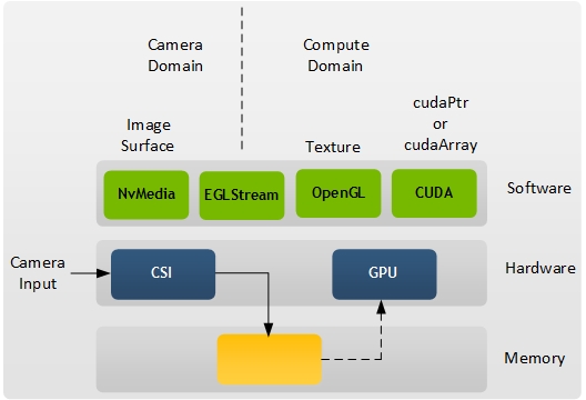
EGLStream Interoperability
The NvMedia EGLStream component supports GL/CUDA interoperability of the NvMedia domain. EGLStream provides the interface to post or retrieve the raw YUV or RGB images. It provides the channel of communication to connect the NvMedia domain with GL/CUDA domain. Any NvMedia surface can be rendered on the screen using any type of consumer using EGLStream.
NvMedia EGLStream component provides the following features:
• Supports the Khronos EGLStream specification
• Maps camera input image data to CPU
• Provides images to GL as textures
• Provides images to CUDA as cudaPtr or cudaArray
• Requires no extra memory copy for GPU processing
• Provides multi-threaded or multi-process sharing
• Provides ‘mailbox’ or ‘fifo’ mode of transfer
This interoperability feature of NvMedia EGLStream makes it useful in many applications. You can easily realize NvMedia Image, Video producers/consumers interacting with GL/CUDA producers/consumers.
The following diagram show how camera input is processed.
NvMedia Image Sensor Control (ISC)
The NvMedia ISC provides a framework for image sensor control. It includes programming I2C controlled external components such as aggregators, and image sensors. It provides the following features:
• Supports addition of custom drivers
• Sends the control commands to hardware devices related to image sensor
• Reports errors during image capture
• Powers on/off the cameras
• Supports debugfs
• Powers on/off
• Checks status of power
NvMedia ISC exposes a user space interface that supports configuring and controlling the sensors, aggregating, and serializing. In addition, it can turn on and configure the camera inputs and respond to interrupts.