Image Capture Calibrate (nvmimg_cc)
The NvMedia Capture Calibration sample demonstrates how to bring up or validate the camera sensor. It also demonstrates how to capture sensor data to raw files for camera calibration.
The sample application parses a script file with the necessary I2C commands and sends them to the designated sensor(s). The sensor name must be specified in the command option.
Warning: | Do NOT use this sample application for production environments. For best practices, use the sample to perform hardware bring-up of serializer/deserializer and sensor modules. This sample is NOT intended for performance on multiple cameras, stress testing, or testing of the start/stop of applications. |
The following settings can be configured through the command line, depending on the sensor:
• Sensor ar0231:
• Number of exposure, maximum number of exposure
• Exposure times, separate for T1, T2, T3 and T4 exposures
• Digital gain for all exposures
• Analog and conversion gains, separate for T1, T2, T3 and T4 exposures
• White balance color gain, separate for R/Gr/Gb/B
• User defined 12 points of companding knee LUT
• Sensor ov10640:
• Exposure times, separate for long, short, and very short exposures
• Analog and digital gain for long, short, and very short exposures through the command line
• Conversion gain, separate for long and very short exposures
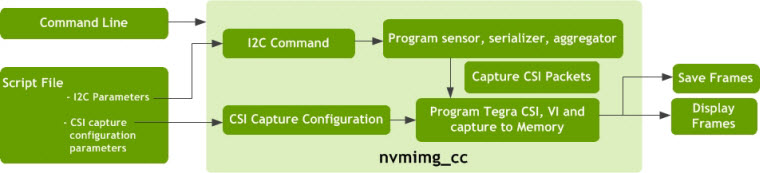
The sample application requires the user to provide command line input and a script file. The script file contains two sets of information:
• I2C parameters that translate to I2C commands for programming the camera module (sensor, serializer), aggregator.
• CSI capture configurations used to program the Tegra CSI and Video Input (VI) modules.
The CSI packets from the aggregator reach Video Input (VI) module and are saved to memory. The frames are displayed using Display Controller (DC) or saved to a file.
The following image provides an overview of the process.
Command Options
Note: | The nvmimg_cc application must be run with the root user to allow the application to access the I2C bus and to program the camera module. |
The command line options to run the script are as follows.
./nvmimg_cc -wrregs <script_filename> [options]
Where:
<script_filename> is the name of the script file used by the application.
Option | Parameter | Description | Default Settings |
-s | <frames> | Specifies the number of frames to skip after the capture starts and before putting the images onto the display or save queue. | Default: 0 |
-b | <n> | Specifies the number of buffers to use for the buffer pool. | Default: 3
Maximum: 600 |
-wrregs | <filename> | File name of the register script to write to the sensor. | Default: N/A |
-rdregs | <filename> | Saves a dump of the registers from the sensor to the specified file. | Default: Registers are not saved to the file. |
--crystalF | <frequency> | Specifies a crystal frequency, in MHz, for calculations. | Default: 24 |
-n | <frames> | Specifies an exact number of frames to capture. | Default: infinite. |
-f | <file_prefix> | Saves the captures frames to the file. Each file starts with the specified prefix, concatenated with any calibration parameters and the frame index. | Default: frames are not saved to file(s). |
-h | N/A | Print usage | N/A |
-v | [level] | Specifies the logging level. • 0 = Errors • 1 = Warnings • 2 = Info • 3 = Debug If no level is provided, uses 3 (Debug). If the option is not provided, uses 0 (Errors). | Default: 0
If the option is used, but level is not provided, the default is 3. |
-d | [id] | Enables the display. If provided, uses the display with the specified ID. | Default: disable display
If the ID is not provided: use the first available display. |
-w | <id> | Uses the window with the specified ID for display. | Default: 0 |
-z | <depth> | Specifies the depth for display. | Default: 0 |
-cf | [filename] | Specifies the configuration file. Co-locate the file with nvmimg_cc. | N/A |
-c | [name] | Specifies the parameters set name. | N/A |
-p | <x:y:w:h> | Specifies the window position rectangle. | Default: No positioning |
--nvraw | N/A | Saves frames in nvraw format. Valid for raw capture and when frames are saved using the -f option. | Default: if not provided, frames are not saved in nvraw format. |
--wait | [n] | Waits for n frames before capturing the next frame(s). | If not provided, captures every frame |
--miniburst | [n] | Saves n frames after each wait period. Valid when used with the -wait option. | If the option is not provided, n is 1. |
--cam_enable | <0001 to 1111> | Enables or disables the camera, where each bit represents a camera in the [3210] order. In other words, the left-most bit represents camera 3 and the right-most bit, camera 0. Bit settings for each camera are: • Enable: 1 • Disable: 0 Video is not available from the disabled camera. | Default: 0001 |
--cam_mask | <0000 to 1110> | Masks or unmasks the cameras, where each bit represents a camera in the [3210] order. You cannot mask all cameras, which means that 1111 is not allowed. Bit settings for each camera are: • Mask:1 • Unmask:0 | Default: 0000 |
--csi_outmap | <abcd> | Sets the CSI out order for the cameras. The a, b, c, d order can be 0, 1, 2, or 3 in any order. Each number must only be used once. | Default: 3210 |
--pwr_ctrl-off | N/A | Disables power control. | N/A |
--settings | [name] | File containing runtime settings. | N/A |
-sensor | [name] | Specifies the sensor name for sensor calibration. Valid names are ar0231 or ov10640. | No default. |
Sensor AR0231 Calibration Command Options
The following table identifies the options for the AR0231 sensor.
Option | Parameter | Description |
-etl | <time> | Specifies the exposure time (float), in microseconds, for T1. |
-et2 | <time> | Specifies the exposure time (float), in microseconds, for T2. |
-et3 | <time> | Specifies the exposure time (float), in microseconds, for T3. |
-et4 | <time> | Specifies the exposure time (float), in microseconds, for T4. |
-etR1 | <time> | Specifies the exposure time (float), in rows, for T1. |
-etR2 | <time> | Specifies the exposure time (float), in rows, for T2. |
-etR3 | <time> | Specifies the exposure time (float), in rows, for T3. |
-etR4 | <time> | Specifies the exposure time (float), in rows, for T4. |
-dg | <gain> | Specifies the digital gain (float) for T1/T2/T3/T4. |
-ag1 | <gain> | Specifies the analog gain (float) for T1. |
-ag2 | <gain> | Specifies the analog gain (float) for T2. |
-ag3 | <gain> | Specifies the analog gain (float) for T3. |
-ag4 | <gain> | Specifies the analog gain (float) for T4. |
-cg1 | <gain> | Specifies the conversion gain (int) for T1. Valid values are: 0 or 1. |
-cg2 | <gain> | Specifies the conversion gain (int) for T2. Valid values are: 0 or 1. |
-cg3 | <gain> | Specifies the conversion gain (int) for T3. Valid values are: 0 or 1. |
-cg4 | <gain> | Specifies the conversion gain (int) for T4. Valid values are: 0 or 1. |
-wbRGGB | <[g1,...,g4]> | Specifies the 4 white balance gains (float) in form of R/Gr/Gb/B pattern. Valid values are >= 1.0, group inside of []. |
-max_exp | <n> | Specifies the maximum number of exposure. Valid values are: 1 to 4. |
-n_exp | <n> | Specifies the number of exposures. Valid values are: 1 to 4. |
-lkp | <[p1,...,p12]> | Specifies the user-defined 12 keen points companding LUT (16-bit hex number). Valid values are: 0x0 to 0xfff0, effective bit[15:4], left shift 4 bits for 12-bit data; group inside of []. |
Notes and Requirement for ar0231 Calibration
• Use *_hdr_*_ta.script for sensor calibration.
• max_exp and n_exp default values are 3. Required: max_exp >= n_exp
• When you set n_exp to 1, you may also set linear companding LUT with -lkp to get linear data
• Conversion gain = x1.0 when set to 0, = x3.0 when set to 1.
• Maximum digital gain is 3.998.
• Analog gain can be set to:
0.125, 0.25, 0.375, 0.429, 0.5, 0.667, 0.8, 1, 1.25, 1.5, 2, 2.333, 3.5, 4, or 8;
If the set value is between 2 points, the script chooses the lower value. For example, if you specify 3.9, the gain will actually be 3.5.
The vendor recommends setting minimal analog gain to 0.8 in low conversion gain, and to 1.0 in high conversion gain.
• Maximum exposure time
• T2: 61 rows + 1467 pclk. (1467 pclk is the fixed fine integration time)
• T3: 4 rows + 488 pclk. (488 pclk is the fixed fine integration time)
• T4: 0 rows + 573 pclk. (573 pclk is the fixed fine integration time)
• Exposure time minimal difference is 1 row and the fine integration time (x pclk) are fixed for all exposures in silicon V3.
• To get log info about sensor calibration actual settings, please specify '-v 2' or '-v'.
Sensor OV10640 Calibration Command Options
The following table identifies the options for the OV10640 sensor.
Option | Parameter | Description |
-etl | <time> | Specifies the exposure time, in microseconds, for long. |
-ets | <time> | Specifies the exposure time, in microseconds, for short. |
-etvs | <time> | Specifies the exposure time, in microseconds, for very short. |
-dgl | <gain> | Specifies the digital gain (float) for long. |
-dgs | <gain> | Specifies the digital gain (float) for short. |
-dgvs | <gain> | Specifies the digital gain (float) for very short. |
-agl | <gain> | Specifies the analog gain (int) for long. Valid values are: 1, 2, 4, or 8. |
-ags | <gain> | Specifies the analog gain (int) for short. Valid values are: 1, 2, 4, or 8. |
-agvs | <gain> | Specifies the analog gain (int) for very short. Valid values are: 1, 2, 4, or 8. |
-cgl | <gain> | Specifies the conversion gain (int) for long. Valid values are: 0 or 1. |
-cgvs | <gain> | Specifies the conversion gain (int) for very long. Valid values are: 0 or 1. |
Script File
A script file contains the following components:
• Configuration parameters
• I2C commands to program the camera sensor, deserailizer and serializer
• Additional commands used by the application
Script File Configuration Parameter Options
The script file configuration parameter options are as follows.
Parameter | Description | Valid Values and Examples |
;Interface: | Capture interface | csi-a, csi-b, csi-ab, csi-cd, csi-e |
;Input Format: | Input frame format | 422p, raw12, raw2x11, raw3x12, raw16log |
;Surface Format: | CSI surface format | yv16, rgb, raw8, raw10, raw12 |
;Resolution: | Input frame resolution | <width>x<height> |
;Pixel Order: | Bayer pixel color order | GRBG, GBRG, RGGB, BGGR (default) |
;I2C Device: | I2C device to be used for configuring CSI device | 0: NVMEDIA_ISC_I2C_PORT_A
1: NVMEDIA_ISC_I2C_PORT_B
2: NVMEDIA_ISC_I2C_PORT_C
3: NVMEDIA_ISC_I2C_PORT_D |
;Sensor Address: | 8-bit device address of the sensor | 0x60: OV10635; 0x60: OV10640; 0x20: AR0231 |
;Max9286 Address: | 8-bit address of the aggregator device | 0xd4: E1859 + CSI-AB
0xd8: E1859 + CSI-CD
0x90: P2360 + CSI-AB
0x94: P2360 + CSI-CD |
;Begin preset registers ;End preset registers | Contains the registers that must be written before capture settings have been configured on the Tegra side. | ; Begin preset registers xx xxxx xx yy yyyy yy ; End preset registers In this case, I2C commands xx xxxx xx and yy yyyy yy are written to the camera device before capture settings have been configured on Tegra. |
Script File I2C Command Parameter Options
The script file I2C command parameter options are as follows:
Parameter | Description | Valid Values and Examples |
<Device>
<Register> | Device: 8-bit address of the device, in hexadecimal format. Register: 1 or 2-byte address of register, in hexadecimal format. Value: 1-byte hexadecimal value that is written to the provided device and register address. | <example_of_programming_sensor> 60: Device 3013: Register 01: Value |
Script File Additional Commands Parameter Options
The script file I2C command parameter options are as follows:
Command Type | Parameter | Description | Valid Values and Examples |
Delay | ;Delay <time> (ms/us) | Delays the execution of the next line in the sccript by the provided time and unit. Use ms for milliseconds, and us for microseconds. | <example of 10uS> ;Delay 10us |
Open I2C device | ;I2C <number> | Opens a new I2C handle with the provided device number. | <Example of selecting I2C 0> ;I2C 0 |
Scheduling of sensor programming | ;Wait for frame <number> ;End frame <number> registers | Use these commands to send I2C commands to the device at a specific point of capture by specifying the frame number. The End frame <number> registers command signals the end of the I2C commands that are sent tfor the specified frame number. | 60 30e6 02 # example i2c command ;End Frame 4 registers |
Configuration Parameters
Each script file must start with a list of configuration parameters. These parameters are used by the application to determine the capture settings. The required parameters include:
; Interface: <type>
; Input Format: <format>
; Resolution: <resolution>
; CSI Lanes: <number of lanes>
; I2C Device: <device number>
; Sensor Address: <address>
• Interface: specifies the CSI interface type being used.
• Input Format: specifies the format for which the sensor is capturing images.
• Resolution: specifies the resolution for which the sensor is capturing. This includes embedded lines.
• CSI Lanes: specifies the number of CSI lanes being used.
• I2C Device: specifies the ID of the I2C device that is connected to the aggregator.
• Sensor address: specifies the address of the sensor used for I2C.
Additional optional configuration parameters include:
; Surface Format: <surface format>
; Max9286 ,or Deserializer> Address: <address>
; Pixel Order: <format>
• Surface Format: specifies the CSI surface format. If this is not provided, the application chooses a default surface format based on the input format.
• Max9286 (or Deserializer) address: provides additional debug information by dumping the registers of the aggregator.
• Pixel Order: Bayer pixel color order
The following provides an example configuration for the P2360 board.
; Interface: csi-ab
; Input Format: raw12
; Resolution: 1280x1084
; CSI Lanes: 4
; I2C Device: 2
; Sensor Address: 0x60
; Max9286 Address: 0x90
I2C Commands
Each I2C command includes the following format.
<device> <register> <value>
• Device: the address of the device.
• Register: the address of the register to write to.
• Value: the value that will be written to the register.
The device and value must be a one-byte number, in hexadecimal format. While the register can be either a 1 or 2-byte number in hexadecimal format.
For example:
60 3013 01
• 60 is the device address, in hexadecimal format.
• 3013 is the 2-byte register to write to, in hexadecimal format.
• 01 is the value that will be written to the register, in hexadecimal format.
The Delay Command
There are additional commands that can be used in the script file. These are denoted with a semicolon (;). The delay command is a useful command used to wait for a specified amount of time between I2C writes to the device. The delay command format is as follows:
; Delay <time>(ms/us)
• Time: an integer representing the amount of time.
• ms/us: the unit of time. ms is milliseconds. us is microseconds.
For example:
; Delay 10ms
The application waits for 10 milliseconds before executing the next command in the script file.
Open I2C Device
You can use the script file to specify the I2C device number. The format is as follows:
; I2C <id>
• <id> is the I2C device number.
For example:
; I2C 1
The I2C handle is opened for I2C device 1. Any consequent I2C commands will use this handle. If this command is used again, it closes the existing handle before opening the handle for the new I2C device.
Scheduling of Sensor Programming
The script allows I2C commands to be sent to the sensor at a certain point of time of capture. This is performed by specifying a frame in the script where any consequent I2C commands are written to the sensor after that frame has been captured. The command format is as follows:
; Wait for frame <frame number>
In addition to this command, the end of these commands must be specified by using the following command:
; End frame <frame number> registers
For example:
; Wait for frame 10
xx xxxx xx
yy yyyy yy
; End frame 10 registers
I2C commands xx xxxx xx and yy yyyy yy are written to the sensor after frame 10 has been captured.
Comments
Comments begin with a pound sign (#). The text that appears after the pound sign to the end of the line is a comment and is not parsed by the script file parser.
Example Commands
The following examples represent commonly used commands.
• For DRIVE PX 2 AutoChauffeur the board name is e2379_c01.
• For DRIVE PX 2 AutoCruise the board name is p3407_a00.
To skip the first 10 frames
• Run:
./nvmimg_cc -wrregs dvp_m_ov10635_yuv422_1280x802_ab_ta.script -d 0 -w 1 -f frame -n 10 -s 10
To capture RAW12 frames
The following code example shows how to capture RAW12 frames from the sensor OV10640 and display on the screen on the CSI port AB:
• Run:
./nvmimg_cc -wrregs dvp_m_ov10635_yuv422_1280x802_ab_ta.script -d 0 -w 1
To capture RAW12 frames with additional calibration commands
The following code example shows how to capture RAW12 frames from sensor AR0231 and display on the screen on the CSI port AB with additional calibration commands to set exposure times, gains, knee LUT, etc. as needed:
• Run:
./nvmimg_cc -wrregs dvp_m_ov10635_yuv422_1280x802_ab_ta.script -d 0 -w 1 -sensor ar0231 -et1 31233 -et2 1370 -ag3 2.5 -dg 2.4 -cg2 1 -ag2 1.3 -ag1 1.4 -wbRGGB [1.4,1.0,1.0,1.5] -lkp [2000,3400,4800,5c00,7100,8500,9900,ae00,c200,d600,eb00,0Xf800] -n_exp 3 -v
To capture YUV422 frames
The following code example shows how to:
1. Capture ten YUV422 frames from sensor OV10635.
2. Store the frames to a file.
3. Save the filenames prefixed with "frame" (files are named frame_0.raw, frame_1.raw, etc.).
4. Display on to the screen the CSI port AB.
To capture, run the following command:
./nvmimg_cc -wrregs dvp_m_ov10635_yuv422_1280x802_ab_ta.script -d 0 -w 1 -f frame -n 10
To capture YUV422 frames from three cameras
The following code example shows how to:
1. Capture YUV422 frames from three cameras using sensor OV10635.
2. Disable camera 2.
3. Mask camera 0.
4. Adjust the CSI output order. In this case, the csi_outmap has to be set to x3xx.
5. Set the display onto the screen on the CSI port AB.
To capture, run the following command:
./nvmimg_cc -wrregs dvp_m_ov10635_yuv422_1280x802_ab_ta.script -d 0 -w 1 --cam_enable 1011 --cam_mask 0001 --csi_outmap 1302
Troubleshooting
Several situations can cause generic video link errors.
TVMRCaptureGetErrorStatus - No Frame Start
The following error message applies to DRIVE PX 2 AutoChauffeur, DRIVE PX 2 AutoCruise does not include camera group C and therefore does not include the xxx_ef_ta.script:
./nvmimg_cc -wrregs dvp_m_ov10635_yuv422_1280x802_ab_ta.script -d 0 -w 1
Used display - Display Info - Enabled:1 displayId:0 type:B306
size:1920x1200 ref
resh:59.954842 type:HDMI
[ 548.335352] nvmap_pgprot: PID 377: nvmimg_cc: TAG: 0x1100
WARNING: NVMAP_HAN DLE_WRITE_COMBINE should be used in place of
NVMAP_HANDLE_UNCACHEABLE on ARM64 Capturing Frames...
TVMRCaptureGetErrorStatus: no frame start
NvMediaICPGetFrame: dev get frame yuv failed (error 2)
nvmedia: ERROR: CaptureThreadFunc: NvMediaICPGetFrame failed
[ 549.349909] vi vi: error notifier set to 1 [ 549.357866] vi vi:
error notifier set to 1 [ 549.365458] vi vi: error notifier set to 1
TVMRCaptureGetErrorStatus: no frame start
NvMediaICPGetFrame: dev get frame yuv failed (error 2)
nvmedia: ERROR: CaptureThreadFunc: NvMediaICPGetFrame failed
nvmedia: ERROR: CaptureThreadFunc: BufferPool_AcquireBuffer failed 7
Possible causes include:
• The connections may be incorrect; such as the video link or the configuration link are not present. To rule out this option, refer to the the Platform Setup topic to identify the correct camera connections for your platform.
• A conflict in the command line may have been entered, and the script used to program the camera sensors is using nvmimg_cc. For example, the script may enable one camera link while the command line is expecting the data to arrive from all four links, in which case, there is no CSI frame for the other links. If you are using nvmimg_cc, verify that the script and the command line are synchronized.
TVMRCaptureGetErrorStatus: No Line Packet
Tegra receives the start of the frame during the capture, but no packets are sent later to Tegra. This issue is observed in the following scenarios:
• The camera is disconnected after the start of the frames are sent to Tegra.
• Using a faulty sensor that sends the start of the frame but no other packets later.
TVMRCaptureGetErrorStatus: Incomplete Frame
The following error message applies to DRIVE PX 2 AutoChauffeur, DRIVE PX 2 AutoCruise does not include camera group C and therefore does not include the xxx_ef_ta.script:
./nvmimg_cc -wrregs dvp_m_ov10635_yuv422_1280x802_ab_ta.script
Capturing Frames...
TVMRCaptureGetErrorStatus: uncompleted frame
NvMediaICPGetFrame: dev get frame yuv failed (error 3)
nvmedia: ERROR: CaptureThreadFunc: NvMediaICPGetFrame failed
TVMRCaptureGetErrorStatus: uncompleted frame
NvMediaICPGetFrame: dev get frame yuv failed (error 3)
nvmedia: ERROR: CaptureThreadFunc: NvMediaICPGetFrame failed
nvmedia: ERROR: CaptureThreadFunc: BufferPool_AcquireBuffer failed 7
An incomplete frame was received by Tegra over the CSI interface. The camera source stopped sending CSI packets to Tegra in the middle of the capture.
Possible causes include:
• If the camera module has lost power in the middle of the capture. Verify that the camera module power is always turned on during the capture.
• The GMSL link is broken between the camera and Tegra. Confirm the functionality of the links.
TVMRCaptureGetErrorStatus: CSI Packet Error
The following error message applies to DRIVE PX 2 AutoChauffeur, DRIVE PX 2 AutoCruise does not include camera group C and therefore does not include the xxx_ef_ta.script:
./nvmimg_cc -wrregs dvp_m_ov10635_yuv422_1280x802_ab_ta.script
Capturing Frames...
TVMRCaptureGetErrorStatus: csi packet error
NvMediaICPGetFrame: dev get frame yuv failed (error 4)
nvmedia: ERROR: CaptureThreadFunc: NvMediaICPGetFrame failed
TVMRCaptureGetErrorStatus: csi packet error
NvMediaICPGetFrame: dev get frame yuv failed (error 4)
nvmedia: ERROR: CaptureThreadFunc: NvMediaICPGetFrame failed
nvmedia: ERROR: CaptureThreadFunc: BufferPool_AcquireBuffer failed 7
A generic CSI packet error has occurred during the capture.
Possible causes include:
• Image resolution mismatch between the captured images from camera and expectation of the Tegra side.
• Image format (raw, yuv) mismatch between camera and Tegra sides.
• Noise/signal integrity for the CSI link between camera and Tegra.
TVMRCaptureGetErrorStatus: Can't Detect Error
A generic error from the CSI driver can occur when the CSI error does not fall into any of the categories specified above.
I2C No Acknowledgement Error
This error occurs if a wrong sensor/serializer/aggregator address is in the script file. A mismatch may have occurred between the I2C bus in the kernel device tree versus the programming script.
The error message is as follows:
./nvmimg_cc -wrregs dvp_m_ov10635_yuv422_1280x802_ab _ta.script
nvmedia: ERROR: I2cProcessCommands: Failed to write to I2C 72 3f 62
nvmedia: ERROR: ImageCapture_Init: Failed to write to registers over I2C
nvmedia: ERROR: ImageCapture_Init: Failed to initialize image capture
nvmedia: ERROR: main: Failed to initialize Test
root@nvidia:/home/nvidia# dmesg | grep i2c
[ 10.035521] i2c /dev entries driver
[ 10.037007] 546c0000.i2c supply bus-pullup not found, using dummy regulator
[10315.585162] tegra-i2c 7000c500.i2c: no acknowledge from address 0x72
• Use i2cdetect to detect the devices on the I2C bus that are currently used.
• Browse the platform schematic to verify the correct address of the aggregator to be programmed.
I2C Programming Error
The error message is as follows:
./nvmimg_cc -wrregs dvp_m_ov10635_yuv422_1280x802_ab _ta.script
nvmedia: ERROR: I2cProcessCommands: Failed to write to I2C 40 04 43
nvmedia: ERROR: ImageCapture_Init: Failed to write to registers over I2C
nvmedia: ERROR: ImageCapture_Init: Failed to initialize image capture
nvmedia: ERROR: main: Failed to initialize Test
• Confirm the correct camera connections as described in Platform Setup topic.
• Confirm the I2C speed for programming is 400 Khz.
• cat /sys/kernel/debug/clock/clock_tree | grep i2c
• Check if a delay component is needed. The serializer takes approximately 7ms to enable the reverse channel. Consequently, a delay is required after programming 04 43 as shown in the above error message. This varies depending on the serializer and camera module in use.
80 04 43
; Delay 7ms
• Possible settings in the script and the modules involved are as follows:
Device | Offset Register | Value | Description |
Aggregator | 00 | E1
E3
E7
EF | Enable link 0
Enable Link 0, 1
Enable Link 0, 1, 2
Enable link 0, 1, 2, 3 |
Aggregator | 15 | 03
0B | Disable CSI out
EnableCSI out |
Serializer | 04 | 43
83 | Disable Serial Link and enable configuration link.
Enable Serial Link and disable configuration link. |
Aggregator | 3B | 1B | Set Reverse channel transmitter time to 200 ns.
Set Reverve channel transmitter pulse amplitude to 80mv.
Add 60mV to reverse channel amplitude. |
Aggregator | 3F | 62 | Enable reverse channel parameters custom programming. |
Serializer | 07 | 94 | Reserved |
Aggregator | 12 | Bits[7:6]=00
Bits[7:6]=01
Bits[7:6]=10
Bits[7:6]=11
Bits[3:0]=0000
Bits[3:0]=0011
Bits[3:0]=0101
Bits[3:0]=0110
Bits[3:0]=0111 | Data lane D0 enabled.
Data lane D0, D1 enabled.
Data lane D0, D1, D2 enabled.
Data lane D0, D1, D2, D3 enabled.
RGB888 data type.
YUV422 8-bit data type.
RAW 8 data type.
RAW 10 data type.
RAW 12 data type. |
Aggregator | 01 | Bits[7:6]=00
Bits[7:6]=11
Bits[1:0]=1*
Bits[1:0]=01 | Frame sync generation is On.
Frame sync generation is Off.
Auto frame sync method.
Semi-auto frame sync method. |
Aggregator | 34 | Bit[7]=1
Bit[7]=0 | I2C-to-I2C slave generates local acknowledge when forward channel is not available.
I2C-to-I2C slave does not generate local acknowledge when forward channel is not available. |
Aggregator | 34 | FF | Enable forward control and reverse control channel to/from serializer for links 0, 1, 2, 3. |
Cannot Open the ISC Manager
The error message is as follows:
./nvmimg_cc -wrregs dvp_m_ov10635_yuv422_1280x802_ab_ta.script
iscRootDevOpen: can't open /dev/isc-mgr.3.a - No such file or directory
NvMediaISCRootDeviceCreate: Unable to open root device
nvmedia: ERROR: ImageCapture_PowerOn: Failed to create NvMedia ISC root device
nvmedia: ERROR: ImageCapture_Init: Failed to power on
nvmedia: ERROR: ImageCapture_Init: Failed to initialize image capture
nvmedia: ERROR: main: Failed to initialize Test
This error commonly occurs when a wrong I2C device is used in the DTS file or in the script file. Verify the configuration present in the device, at the following location, matches the on in the script.
cat <KERNEL_TOP>/arch/arm64/boot/dts/<platform.dtsi>
This error occurs if the I2C device is incorrectly initialized. A specific I2C device must be associated with the given CSI port.
cat /dev/isc-mgr.<i2c dev>.<csi port>
i2c dev = <0,..6>
csi port = <a, c, e>
Failed to Create Image Display
The error message is as follows:
./nvmimg_cc -wrregs dvp_m_ov10635_yuv422_1280x802_ab_ta.script -d 1
nvmedia: ERROR: ImageDisplayCreate: No display created
nvmedia: ERROR: ImageDisplayCreate: Failed to create ImageDisplay
nvmedia: ERROR: NvMTestDisplayCreate: No image display created
nvmedia: ERROR: NvMTestDisplayCreate: Failed to create NvMTestDisplay
nvmedia: ERROR: ImageCapture_Init: Failed to create ImageDisplay context
nvmedia: ERROR: ImageCapture_Init: Failed to initialize image capture
nvmedia: ERROR: main: Failed to initialize Test
This error occurs if the display device creation fails. The likely cause is that a wrong display ID is provided in the command line. The nvmimg_cc application automatically detects the display ID. Run the application again using the -h option to identify the correct display ID.
./nvmimg_cc -h
Available command line options:
-h Print usage
-v [level] Logging Level. Default = 0
0: Errors, 1: Warnings, 2: Info, 3: Debug
Default: 0
-d [n] Set display ID
Available display devices (1)
Display ID : 0 (hdmi)
If multiple display devices are detected, the -d option selects the first device; if the ID is not specified. An error may result if the display ID is unusable.
FlipQ Create Failed
The error message is as follows:
NvMediaIDPCreate: FlipQ create failed (display: 0 window: 0)
nvmedia: ERROR: ImageDisplayCreate: Failed to create NvMedia display
nvmedia: ERROR: ImageDisplayCreate: Failed to create ImageDisplay
nvmedia: ERROR: NvMTestDisplayCreate: No image display created
nvmedia: ERROR: NvMTestDisplayCreate: Failed to create NvMTestDisplay
nvmedia: ERROR: Capture_Init: Failed to create test display
nvmedia: ERROR: Capture_Init: Failed to initialize ImgCapture
nvmedia: ERROR: main: Failed to Initialize ImgCapture
Each display ID and window ID combination yields a unique NvMedia output surface. This error occurs if this combination is already being used by any other application. Verify, on the target, if any other application is using the current output surface combination.